EP1245865A2 - Toroidal type continuously variable transmission - Google Patents
Toroidal type continuously variable transmission Download PDFInfo
- Publication number
- EP1245865A2 EP1245865A2 EP02005525A EP02005525A EP1245865A2 EP 1245865 A2 EP1245865 A2 EP 1245865A2 EP 02005525 A EP02005525 A EP 02005525A EP 02005525 A EP02005525 A EP 02005525A EP 1245865 A2 EP1245865 A2 EP 1245865A2
- Authority
- EP
- European Patent Office
- Prior art keywords
- power
- roller
- shaft
- input
- trunnion
- Prior art date
- Legal status (The legal status is an assumption and is not a legal conclusion. Google has not performed a legal analysis and makes no representation as to the accuracy of the status listed.)
- Granted
Links
Images









Classifications
-
- F—MECHANICAL ENGINEERING; LIGHTING; HEATING; WEAPONS; BLASTING
- F16—ENGINEERING ELEMENTS AND UNITS; GENERAL MEASURES FOR PRODUCING AND MAINTAINING EFFECTIVE FUNCTIONING OF MACHINES OR INSTALLATIONS; THERMAL INSULATION IN GENERAL
- F16H—GEARING
- F16H15/00—Gearings for conveying rotary motion with variable gear ratio, or for reversing rotary motion, by friction between rotary members
- F16H15/02—Gearings for conveying rotary motion with variable gear ratio, or for reversing rotary motion, by friction between rotary members without members having orbital motion
- F16H15/04—Gearings providing a continuous range of gear ratios
- F16H15/06—Gearings providing a continuous range of gear ratios in which a member A of uniform effective diameter mounted on a shaft may co-operate with different parts of a member B
- F16H15/32—Gearings providing a continuous range of gear ratios in which a member A of uniform effective diameter mounted on a shaft may co-operate with different parts of a member B in which the member B has a curved friction surface formed as a surface of a body of revolution generated by a curve which is neither a circular arc centered on its axis of revolution nor a straight line
- F16H15/36—Gearings providing a continuous range of gear ratios in which a member A of uniform effective diameter mounted on a shaft may co-operate with different parts of a member B in which the member B has a curved friction surface formed as a surface of a body of revolution generated by a curve which is neither a circular arc centered on its axis of revolution nor a straight line with concave friction surface, e.g. a hollow toroid surface
- F16H15/38—Gearings providing a continuous range of gear ratios in which a member A of uniform effective diameter mounted on a shaft may co-operate with different parts of a member B in which the member B has a curved friction surface formed as a surface of a body of revolution generated by a curve which is neither a circular arc centered on its axis of revolution nor a straight line with concave friction surface, e.g. a hollow toroid surface with two members B having hollow toroid surfaces opposite to each other, the member or members A being adjustably mounted between the surfaces
Definitions
- power outer roller 212 is brought into contact with an inner side wall of power roller receiving recess 202 when a vertical load (viz., load applied in the direction of the trunnion pivot axis) is applied to the power roller 206. If such contact occurs, smoothed parallel displacement of power roller 206 may be sacrificed.
- a vertical load viz., load applied in the direction of the trunnion pivot axis
- power rollers 18c, 18d, 20c and 20d are subjected to inclination in accordance with a needed transmission ratio, so that rotation of input discs 18a and 20a is transmitted to output discs 18b and 20b while continuously changing the speed thereof.
- the sliding operation of power roller 18c can absorb or cope with the distance change between two discs 18a and 18b. Furthermore, even when input and output discs 18a and 18b are subjected to deformation and/or misalignment which would occur upon assembly, the sliding operation of power roller 18c can absorb or cope with such undesired phenomena.
- the coupling between two parts 92 and 94 is detachably made by a meshed engagement. That is, as shown in the drawing, shaft 94 is formed on its left end with an external thread 94e and power outer roller 92 is formed on an inner surface of cylindrical bore 92c thereof with an internal thread 92f. Upon assembly to trunnion 17a, internal thread 92f of power outer roller 92 is tightly engaged with external thread 94e of the left end of shaft 94.
- power outer roller 92' is permitted to have a relative rotation operation to power inner roller 91.
- force produced upon power transmission between input or output disc 18a or 18b and power inner roller 91 is transmitted through ball bearing 93 to power outer roller 92' and thus when the force applied to power outer roller 92' includes a force that rotates power outer roller 92', power outer roller 92' is shifted while permitting rotation thereof. That is, due to provision of annular clearance "t", power outer roller 92' is permitted to make rotation and shifting relative to shaft 94' by a degree corresponding to the clearance "t".
- the power roller supporting structure of this embodiment 100H is similar to that of the above-mentioned seventh embodiment 100G.
- the device of this eighth embodiment 100H there is defined a lubricant oil groove 101 between the flat surface 92g of power outer roller 92' and the flat front surface 94f of power roller holding portion 94h.
- the power roller supporting structure is of a so-called slide type.
- a swing type employed in conventional toroidal type continuously variable transmissions may be used for such supporting structure.
Landscapes
- Engineering & Computer Science (AREA)
- General Engineering & Computer Science (AREA)
- Mechanical Engineering (AREA)
- Friction Gearing (AREA)
Abstract
Description
- The present invention relates in general to transmissions of motor vehicles, and more particularly to toroidal type continuously variable transmissions of wheeled motor vehicles.
- Hitherto, various toroidal type continuously variable transmissions have been proposed and put into practical use in the field of motor vehicles, for the easiness with which the motor vehicle having such transmission mounted thereon can be driven and handled.
- Usually, to constantly keep operative contact between each of input and output discs and each of pared power rollers, the transmissions of such type are equipped with a loading cam device by which the distance between the input and output discs is adjusted in accordance with inclination of the power rollers. That is, the loading cam device functions to move the input disc axially relative to the output disc. However, since the pivot axis of the trunnion is an axis that is fixed, the operative contact of the power rollers to the input and output discs achieved by adjustment of the distance between the input and output discs by the loading cam device needs a movement of each power roller in a given direction perpendicular to both the rotation axis of the power roller and the trunnion pivot axis. Particularly, the movement of each power roller in such a given direction is needed when due to long usage, operation surfaces of such input and output discs have become deformed and/or when the input and output discs and the power rollers are subjected to a misalignment upon assembly.
- Thus, in the transmissions of the above-mentioned type, a so-called "power roller supporting structure" is employed by which the movement of each power roller in such direction is carried out.
- One of the power roller supporting structures is shown in Laid-open Japanese Patent Application (Tokkaihei) 11-159590. In the structure of this publication, there is employed a pivot shaft which supports the power roller and the trunnion on mutually eccentric portions, so that pivot movement of the power roller permits movement of the same in such a given direction.
- Another power roller supporting structure is shown in Laid-Open Japanese Patent Application (Tokkaihei) 7-198014. The supporting structure of this publication is constructed to eliminate or minimize undesired torque shift of transmission.
- The power roller supporting structure of 7-198014 publication is schematically illustrated in Fig. 12 of the accompanying drawings. As shown, a power
roller receiving recess 202 is formed in atrunnion 200, which extends along the common axis of input and output discs (not shown).Linear bearings power roller 206 in therecess 202 and an inner wall of therecess 202. With this construction, thepower roller 206 can move in a given direction to effect a parallel displacement thereof. As shown, thepower roller 206 comprises a powerinner roller 208, a power roller bearing (ball bearing) 210, a powerouter roller 212 and ashaft 214 integral with powerouter roller 212. In this supporting structure, it tends to occur that under operation, powerouter roller 212 is brought into contact with an inner side wall of powerroller receiving recess 202 when a vertical load (viz., load applied in the direction of the trunnion pivot axis) is applied to thepower roller 206. If such contact occurs, smoothed parallel displacement ofpower roller 206 may be sacrificed. - Considering the above, the applicants have thought out some ideas which are depicted by Figs. 13 and 14 of the accompanying drawings.
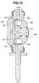
- Fig. 13 depicts an idea that may eliminate the weak point of the structure of the 7-198014 publication. As shown, two
roller bearings roller receiving recess 202 and powerouter roller 212. Due to provision ofroller bearings power roller 206 is achieved. Designated bynumeral 200a is a pivot axis of thetrunnion 200. - Fig. 14 depicts another idea. Also in this idea, two
roller bearings roller receiving recess 202 and powerouter roller 212. However, as shown, in this idea, each roller bearing 220 or 222 is arranged between an inclined flat portion of the inner wall of therecess 202 and an inclined flat portion of powerouter roller 212. Due to provision of suchinclined roller bearings power roller 206 as well as a load in the direction of the trunnion pivot axis are effectively supported bytrunnion 200, and due to the same reason, smoothed parallel displacement ofpower roller 206 is achieved. - However, even the power roller supporting structures described hereinabove fail to satisfy manufacturers. That is, it is quite difficult to machine power
outer roller 212 because of obstruction byshaft 214 that is integral withroller 212. In fact, due to such obstruction, producing an annular guide groove for power roller bearing (ball bearing) 210 needs a time-consumed and skilled machining technique, which increases the cost of the transmission. - Accordingly, an object of the present invention is to provide a toroidal type continuously variable transmission which is free of the above-mentioned weak points.
- According to the present invention, there is provided a toroidal type continuously variable transmission which comprises a power outer roller and a shaft which are produced as separate members. The power outer roller is machined with an annular guide groove for a power roller bearing (ball bearing). Upon assembly, the shaft is coupled with the power outer roller. With this, economical production of power roller supporting structure is achieved while suppressing undesired inclination phenomenon of the shaft.
- According to a first aspect of the present invention, there is provided a toroidal type continuously variable transmission which comprises input and output discs coaxially arranged; a pair of power rollers, each being operatively disposed between the input and output discs and including a power inner roller which is frictionally engaged with the input and output discs, a power outer roller which receives an axial load applied to the power inner roller from the input and output discs, a ball bearing which is operatively interposed between the power inner and outer rollers and a shaft which receives a radial load applied to the power inner roller from the input and output discs, a pair of trunnions rotatably supporting the power rollers respectively, each trunnion being connected to a transmission case in a manner to pivot about its pivot axis and having a power roller receiving recess for receiving therein corresponding one of the power rollers; and first roller bearings, each being operatively interposed between an inner wall of the power roller receiving recess of the trunnion and a back side of the power roller, so that the power roller is movable relative to the trunnion in a direction perpendicular to both a pivot axis of the trunnion and a rotation axis of the power roller, wherein the shaft is a one-body member comprises a first shaft portion on which the power outer roller is coaxially and tightly disposed and a second shaft portion on which the power inner roller is coaxially and rotatably disposed.
- According to a second aspect of the present invention, there is provided a toroidal type continuously variable transmission which comprises input and output discs coaxially arranged; a pair of power rollers, each being operatively disposed between the input and output discs and including a power inner roller which is frictionally engaged with the input and output discs, a power outer roller which receives an axial load applied to the power inner roller from the input and output discs, a ball bearing which is operatively interposed between the power inner and outer rollers and a shaft which receives a radial load applied to the power inner roller from the input and output discs, a pair of trunnions rotatably supporting the power rollers respectively, each trunnion being connected to a transmission case in a manner to pivot about its pivot axis and having a power roller receiving recess for receiving therein corresponding one of the power rollers; and first roller bearings, each being operatively interposed between an inner wall of the power roller receiving recess of the trunnion and a back side of the power roller, so that the power roller is movable relative to the trunnion in a direction perpendicular to both a pivot axis of the trunnion and a rotation axis of the power roller, wherein the shaft is a one-body member comprises a first shaft portion on which the power outer roller is coaxially and tightly disposed and a second shaft portion on which the power inner roller is coaxially and rotatably disposed, wherein an inner wall of the power roller receiving recess is formed with inclined flat portions against which the first roller bearings abut, and wherein the power outer roller comprises a first surface formed with an annular guide groove which operatively receives the ball bearing, and a second surface formed with inclined flat portions which abut against the first roller bearings respectively.
- According to a third aspect of the present invention, there is provided a toroidal type continuously variable transmission which comprises input and output discs coaxially arranged; a pair of power rollers, each being operatively disposed between the input and output discs and including a power inner roller which is frictionally engaged with the input and output discs, a power outer roller which receives an axial load applied to the power inner roller from the input and output discs, a ball bearing which is operatively interposed between the power inner and outer rollers and a shaft which receives a radial load applied to the power inner roller from the input and output discs, a pair of trunnions rotatably supporting the power rollers respectively, each trunnion being connected to a transmission case in a manner to pivot about its pivot axis and having a power roller receiving recess for receiving therein corresponding one of the power rollers; and first roller bearings, each being operatively interposed between an inner wall of the power roller receiving recess of the trunnion and a back side of the power roller, so that the power roller is movable relative to the trunnion in a direction perpendicular to both a pivot axis of the trunnion and a rotation axis of the power roller, wherein the shaft is a one-body member comprises a first shaft portion on which the power outer roller is coaxially and tightly disposed and a second shaft portion on which the power inner roller is coaxially and rotatably disposed, and wherein the first shaft portion is integrally formed with a flange portion which has a front flat surface which abuts against a rear flat surface of the power outer roller and a rear surface which is formed with inclined flat portions which abut against the first roller bearings respectively.
-
- Fig. 1 is a schematic view illustrating entire construction of a toroidal type continuously variable transmission which is a first embodiment of the present invention;
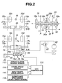
- Fig. 2 is a schematic view illustrating a speed change control system employed in the transmission of the first embodiment;
- Fig. 3 is a vertically sectioned view of a power roller supporting structure employed in the transmission of the first embodiment;
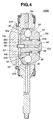
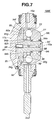
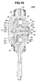
- Figs. 4 to 11 are views similar to Fig. 3, but showing power roller supporting structures employed in second, third, fourth, fifth, sixth, seventh, eighth and ninth embodiments of the present invention, respectively;
- Fig. 12 is a vertically sectioned view of a power roller supporting structure employed in a toroidal type continuously variable transmission of Related Art; and
- Figs. 13 and 14 are views similar to Fig. 3, but depicting less preferred ideas thought out by the applicants.
-
- In the following, various embodiments of the present invention will be described with reference to the accompanying drawings.
- For ease of understanding, directional terms, such as, right, left, upper, lower, rightward, etc., are contained in the following description. However, such terms are to be understood with respect to only a drawing or drawings on which corresponding part or portion is illustrated.
- Referring to Fig. 1, there is schematically shown the entire construction of a toroidal type continuously
variable transmission 100A which is a first embodiment of the present invention. - As shown,
transmission 100A is equipped with atorque converter 12 through which a torque of an engine (not shown) is inputted to an input section of the transmission. -
Torque converter 12 comprises generally apump impeller 12a, aturbine runner 12b, astator 12c, a lock-up clutch 12d, an apply-side fluid chamber 12e and a release-side fluid chamber 12f. Passed through a center oftorque converter 12 is aninput shaft 14. -
Input shaft 14 is connected to a forward/back switch mechanism 36 which is equipped with aplanetary gear unit 42, aforward clutch 44 and aback clutch 46.Planetary gear unit 42 comprises generally asun gear 42c, aring gear 42b and apinion carrier 42a carrying two pinions meshed with bothsun gear 42c andring gear 42b. -
Pinion carrier 42a is connected to atorque transmission shaft 16 around which first and second continuouslyvariable transmission units transmission units transmission case 22.Transmission case 22 has abase 64 in which a control valve system is installed. - First continuously
variable transmission unit 18 comprises input andoutput discs power rollers output discs torque transmission shaft 16, and a pair oftrunnions power rollers variable transmission unit 20 comprises input andoutput discs power rollers output discs torque transmission shaft 16 and a pair oftrunnions power rollers - As shown in Fig. 1, first and
second transmission units output discs loading cam device 34 which produces a pressing force in accordance with an input torque applied thereto fromtorque converter 12,input disc 18a offirst transmission unit 18 is biased in a rightward direction in the drawing.Loading cam device 34 has aloading cam 34a supported bytorque transmission shaft 16 through a bearing 38.Input disc 20a ofsecond transmission unit 20 is biased in a leftward direction by adish spring 40. - As will be apparent hereinafter,
power rollers input discs output discs -
Output discs output gear 28 which is rotatable abouttorque transmission shaft 16, so that a torque transmitted tooutput discs output gear 28 to agear 30a connected to an output shaft 30 (viz., countershaft).Output gear 28 andgear 30a constitute atorque transmission mechanism 32.Gears output shafts idler gear 54 meshed withgears transmission mechanism 48.Output shaft 50 is connected to apropeller shaft 60. - In the following, with the aid of Fig. 2, a speed change control device will be described in detail, which inclines
power rollers - As is seen from Fig. 2, each
power roller corresponding trunnion roller rotation axis trunnion piston trunnion power roller - To operate servo-
pistons hydraulic passage 74 which connects to higher pressure operating chambers of the pistons, a lower pressurehydraulic passage 76 which connects to lower pressure operating chambers of the pistons, and a speedchange control valve 78 which has aport 78a connected to higher pressurehydraulic passage 74 and anotherport 78b connected to lower pressurehydraulic passage 76. Speedchange control valve 78 has further aline pressure port 78c to which a line pressure is applied from a hydraulic source which comprises anoil pump 80 and arelief valve 82. Speedchange control valve 78 has aspeed change spool 78d which is incorporated with alever 84 and aprecision cam 86 to sense an axially moving direction and an inclination direction oftrunnion 17a for controlling speedchange control valve 78 in a feedback controlling manner. Asleeve 78e of speedchange control valve 78 is axially moved by astep motor 88. - A CVT-
controller 110 is provided for controllingstep motor 88. For this controlling, information signals from a throttleopen degree sensor 112, anengine speed sensor 114, an inputshaft speed sensor 116 and an output shaft speed sensor (viz., vehicle speed sensor) 118 are fed tocontroller 110. - In the following, with the aid of Fig. 3, power roller supporting structures for
power rollers - Since these supporting structures for the four power rollers are substantially the same in construction, only the structure for
power roller 18c will be explained for facilitation of the description. -
Trunnion 17a ofpower roller 18c is connected to transmission case 22 (see Fig. 1) in a manner to turn about atrunnion pivot axis 19a which is perpendicular to powerroller rotation axis 15a.Trunnion 17a has at its upper portion a powerroller receiving recess 90 for receivingpower roller 18c. - As is seen from Fig. 3,
power roller 18c comprises a powerinner roller 91 which frictionally contacts both input andoutput discs outer roller 92 which receives or holds an axial load that is applied toinner roller 91 from input andoutput discs outer rollers shaft 94 which receives and holds a radial load that is applied toinner roller 91 from input andoutput discs - As shown, two
roller bearings 95 are arranged betweentrunnion 17a and powerouter roller 92 at opposite positions with respect to powerroller rotation axis 15a. For arranging theseroller bearings 95, two inclined flat spaces are defined at the opposite positions between an inner wall of powerroller receiving recess 90 oftrunnion 17a and a back surface of powerouter roller 92. Due to provision of theseroller bearings 95,power roller 18c can move straightly relative totrunnion 17a in a direction perpendicular to bothtrunnion pivot axis 19a and powerroller ration axis 15a. -
Shaft 94 is shaped into a stepped structure, comprising a smallerdiameter shaft portion 94a on which powerinner roller 91 is rotatably disposed through aroller bearing 96, and a largerdiameter shaft portion 94b onto which powerouter roller 92 is tightly disposed. - Power
outer roller 92 comprises a front surface formed with anannular guide groove 92a operatively receivingball bearing 93, a rear surface formed with inclinedflat portions 92b abutting againstroller bearings 95 and acylindrical bore 92c formed in a center portion thereof for tightly receiving largerdiameter shaft portion 94b (or first shaft portion) ofshaft 94. - Power
outer roller 92 andshaft 94 are separate members. Upon mounting them totrunnion 17a, press-fitting, bonding or shrink-fitting technique is used for securing largerdiameter shaft portion 94b to bore 92c of powerouter roller 92. - In the drawing, denoted by
numeral 97 is a first oil passage formed intrunnion shaft first oil passage 97 tosecond oil passage 98. The lubrication oil led tosecond oil passage 98 is applied toball bearing 93 androller bearings 96 through radial oil passages (not shown) formed inshaft 94. - In the following, operation of toroidal type continuously
variable transmission 100A of the first embodiment will be described. - In toroidal type continuously
variable transmission 100A, the speed change control is carried out by turningtrunnion 17a (andtrunnions pivot axis 19a (and the corresponding pivot axes) thereof to inclinepower roller 18c (andpower rollers - That is, as is understood from Fig. 2, when, upon receiving an instruction signal from CVT-
controller 110,step motor 88 is energized to slidesleeve 78e of speedchange control valve 78 to a desired position, one of two servo piston chambers of each servo-piston trunnion trunnion pivot axis 19a. - With this, the rotation center of each
power roller output discs power roller power roller output discs precision cam 86 andlever 84 to speedchange spool 78d, causingspool 78d to stop at a position where a balance is effected between the force fromlever 84 and that fromstep motor 88. Whenspool 78d has come to the given position, that is, when the power roller has taken a given inclination angle, the displacement given totrunnion output discs power roller power rollers - In the following, the sliding operation of
power rollers - Since these four power rollers exhibit substantially the same movement, only operation of
power roller 18c will be described for facilitation of description. - When
power roller 18c is applied with loads in lateral directions from input andoutput discs roller bearings 95 arranged at the back side ofpower roller 18c are forced to permit a movement ofpower roller 18c in lateral directions relative totrunnion 17a. Even if the loads applied topower roller 18c contain a load in an axial direction and a load in a vertical direction, the vertically spaced arrangement of tworoller bearings 95 assures a satisfied support for such loads bytrunnion 17a, and thus undesired contacting between an inner wall of powerroller receiving recess 90 andpower roller 18c is suppressed assuring a smoothed lateral movement ofpower roller 18c relative totrunnion 17a. - Accordingly, even when the distance between input and
output discs loading cam device 34, the sliding operation ofpower roller 18c can absorb or cope with the distance change between twodiscs output discs power roller 18c can absorb or cope with such undesired phenomena. - As is described hereinabove and shown in Fig. 3,
power roller 18c generally consists of powerinner roller 91, powerouter roller 92,ball bearing 93 andshaft 94. That is, two load receiving sections are separately constructed, one being the powerouter roller 92 which receives an axial load applied to powerinner roller 91 from input andoutput discs ball bearing 93, and the other being theshaft 94 which receives a radial load applied to powerinner roller 91 from input andoutput discs 18a and 18b. Powerouter roller 92 andshaft 94 are machined separately. Thus, grinding ofannular guide groove 92a of powerouter roller 92 is easily carried out. In a conventional structure (see Fig. 12) wherein power outer roller is integral with a shaft, grinding such guide groove needs a difficult and time-consumed work due to interference by the integral shaft. In fact, during the grinding process, the integral shaft tends to interfere with a grinding tool handled by an operator. - Upon assembly to
trunnion 17a, powerouter roller 92 andshaft 94 are coupled, and thus, undesirable inclination ofshaft 94, which would be caused by loads applied to powerinner roller 91 from input andoutput discs outer roller 92 are suppressed or at least minimized. - As is described hereinabove, in the power roller supporting structure of
first embodiment 100A, the two parts, that are, powerouter roller 92 havingannular guide groove 92a forball bearing 93 andshaft 94 are constructed separately, and upon assembly totrunnion 17a, these twoparts parts shaft 94 can be avoided. - In the following, power roller supporting structures employed in second, third, fourth, fifth, sixth, seventh, eighth and
ninth embodiments - Since the power roller supporting structures of these
embodiments 100B to 100I are similar to that of the above-mentionedfirst embodiment 100A, only portions different from those of thefirst embodiment 100A will be described in detail for facilitating description. Substantially same parts are denoted by the same numerals. - Referring to Fig. 4, there is shown a power roller supporting structure employed in a
second embodiment 100B of the present invention. - As shown in the drawing, in this power roller supporting structure, larger
diameter shaft portion 94b is formed at a left end thereof with anannular flange portion 94c which is intimately received in anannular groove 92d formed in powerouter roller 92. Also in this power roller supporting structure, powerouter roller 92 andshaft 94 are produced separately, and then, that is, upon assembly totrunnion 17a, these twoparts first embodiment 100A. For the coupling, press-fitting, bonding or shrink-fitting technique is used. - In the power roller supporting structure of the
second embodiment 100B, substantially same advantages as those of the above-mentionedfirst embodiment 100A are obtained, and because of addition offlange portion 94c engaged withannular groove 92, the coupling between the twoparts - Referring to Fig. 5, there is shown a power roller supporting structure employed in a
third embodiment 100C of the present invention. - In this power roller supporting structure, the coupling between two
parts shaft 94 is formed with an externally threaded smaller diameter leftportion 94d and the powerouter roller 92 is formed with anannular recess 92e that surrounds the smaller diameter leftportion 94d ofshaft 94. Due to provision of theannular recess 92e, anannular flange 92e' of the powerouter roller 92 is formed at a right side of theannular recess 92e. Upon assembly totrunnion 17a, anut 100 received inannular recess 92e is turned in a fastening direction to engage with the external thread ofleft portion 94d ofshaft 94. With this,nut 100 is strongly pressed againstannular flange 92e' of powerouter roller 92 thereby to achieve the tight coupling between twoparts - In the power roller supporting structure of the
third embodiment 100C, substantially same advantages as those of thefirst embodiment 100A are also obtained, and in addition to these advantages, an additional advantage is obtained wherein the coupling between twoparts second embodiments - Referring to Fig. 6, there is shown a power roller supporting structure employed in a
fourth embodiment 100D of the present invention. - In this power roller supporting structure, the coupling between two
parts shaft 94 is formed on its left end with anexternal thread 94e and powerouter roller 92 is formed on an inner surface ofcylindrical bore 92c thereof with aninternal thread 92f. Upon assembly totrunnion 17a,internal thread 92f of powerouter roller 92 is tightly engaged withexternal thread 94e of the left end ofshaft 94. - In the power roller supporting structure of this
embodiment 100D, in addition to the advantages of thefirst embodiment 100A, an additional advantage is obtained wherein the coupling between twoparts - Referring to Fig. 7, there is shown a power roller supporting structure employed in a
fifth embodiment 100E of the present invention. - As shown, in the power roller supporting structure of this embodiment, a power outer roller 92' is shaped into a flat annular member, and a shaft 94' is shaped to have at its left end an
enlarged flange portion 94h which holds the power outer roller 92'. In other words, shaft 94' comprises mutually integrated two portions, one being a power roller holding portion orenlarged flange portion 94h which has a flat front (or right) surface abutting against power outer roller 92' and a rear (or left)race surface 94g abutting againstroller bearings 95, and the other being ashaft portion 94i which rotatably support powerinner roller 91. Power outer roller 92' is constructed to have at its front (or right) side anannular guide groove 92a which operatively receivesball bearing 93, at its rear (or left) side aflat surface 92g which is held by powerroller holding portion 94h of shaft 94' and at its center portion an enlargedcircular opening 92h in whichshaft portion 94i of shaft 94' is intimately received. That is, two parts 92' and 94' are separated at a position quite different from positions in case of theparts fourth embodiments 100A to 100D. - In the power roller supporting structure of this
fifth embodiment 100E, power outer roller 92' and shaft 94' are produced separately. Thus, the advantages of thefirst embodiment 100A are also possessed by the power roller supporting structure of thisfifth embodiment 100A. That is, grinding ofannular guide groove 92a of power outer roller 92' is easily made unlike the case of the conventional structure (see Fig. 12). Furthermore, due to provision of powerroller holding portion 94h which tightly abuts against power outer roller 92', undesired inclination of shaft 94', which would be caused by the load applied to powerinner roller 91 from input andoutput discs embodiment 100E, because of its simple construction, power outer roller 92' can be easily produced. In other words, roller 9 can be precisely constructed at a lower cost. Furthermore, for the same reason, the durability of power outer roller 92' is increased. - Referring to Fig. 8, there is shown a power roller supporting structure employed in a
sixth embodiment 100F of the present invention. - As shown, the power roller supporting structure of this
embodiment 100F is similar to that of the above-mentionedfifth embodiment 100E. However, in the device of thisembodiment 100E, between largerdiameter shaft portion 94b of shaft 94' and an inner surface ofcircular opening 92h of power outer roller 92', there is defined or left an annular clearance "t". - Due to provision of annular clearance "t", the following advantageous operations are obtained in the
sixth embodiment 100F in addition to the advantages possessed by thefifth embodiment 100E. - First, power outer roller 92' is permitted to have a relative shifting operation to power
inner roller 91. That is, under power transmission between each of input andoutput discs inner roller 91, there is produced a force in the direction of thetrunnion pivot axis 19a. Due to this force, power outer roller 92' can smoothly follow powerinner roller 91 even if powerinner roller 91 is shifted towardtrunnion pivot axis 19a. That is, due to provision of annular clearance "t", power outer roller 92' and powerroller holding portion 94h are permitted to make a relative shifting, and thus, when powerinner roller 91 is shifted, power outer roller 92' can follow the shifting. - Second, power outer roller 92' is permitted to have a relative rotation operation to power
inner roller 91. When the force produced upon power transmission between input oroutput disc inner roller 91 is transmitted throughball bearing 93 to power outer roller 92' and thus when the force applied to power outer roller 92' includes a force that rotates power outer roller 92', power outer roller 92' is shifted while permitting rotation thereof. That is, due to provision of annular clearance "t", power outer roller 92' is permitted to make rotation and shifting relative to shaft 94' by a degree corresponding to the clearance "t". - That is, in the power roller supporting structure of the
sixth embodiment 100F, due to the relative rotation and relative shifting of power outer roller 92', a so-called "auto-centering" of the outer roller 92' is established, and thus, respectiveannular guide grooves outer rollers 91 and 92' can precisely holdball bearing 93 and thus elongate the life ofball bearing 93. - Referring to Fig. 9, there is shown a power roller supporting structure employed in a
seventh embodiment 100G of the present invention. - As shown, the power roller supporting structure of this
embodiment 100G is similar to that of the above-mentionedsixth embodiment 100F. However, in the device of thisembodiment 100G, the distance "t2" between largerdiameter shaft portion 94b of shaft 94' and inner surface ofcircular opening 92h of power outer roller 92' is greater than that "t1" between an outer periphery ofroller bearing 96 and an inner surface ofcircular opening 91b of powerinner roller 91. - In this
embodiment 100G, relative movement of powerinner roller 91 is controlled smaller than that of power outer roller 92'. Of course, the advantages of thesixth embodiment 100F are given to theseventh embodiment 100G. More specifically, in theseventh embodiment 100G, the auto-centering function is applied to powerinner roller 91 as well as power outer roller 92'. - In the sixth and
seventh embodiments flat surface 92g of power outer roller 92' and the flat front (or right)surface 94f of powerroller holding portion 94h. With this fine machining, movement of power outer roller 92' in response to that of powerinner roller 91 is smoothly carried out, and thus, auto-centering is smoothly and assuredly achieved by bothrollers 92' and 91. - Referring to Fig. 10, there is shown a power roller supporting structure employed in an
eighth embodiment 100H of the present invention. - As shown, the power roller supporting structure of this
embodiment 100H is similar to that of the above-mentionedseventh embodiment 100G. However, in the device of thiseighth embodiment 100H, there is defined alubricant oil groove 101 between theflat surface 92g of power outer roller 92' and the flatfront surface 94f of powerroller holding portion 94h. - In this
embodiment 100H, the relative rotation and shifting of power outer roller 92' is much smoothly carried out due to provision oflubricant oil groove 101. - Referring to Fig. 11, there is shown a power roller supporting structure employed in a ninth embodiment 100I of the present invention.
- As shown, the power roller supporting structure of this embodiment 100I is similar to that of the above-mentioned
eighth embodiment 100H. However, in the device of this ninth embodiment 100I, there is further provided a lubricantoil flow passage 102 which extends diametrically across largerdiameter shaft portion 94b of shaft 94' to feedlubricant oil groove 101 with a lubricant oil that is led into an axially extendinglubricant oil passage 98 formed in shaft 94'. - In this embodiment 100I, due to provision of
oil flow passage 102, feeding of lubricant oil tooil groove 101 is effectively made and thus the relative rotation and shifting of power outer roller 92' is much more effectively carried out than in the above-mentionedeighth embodiment 100H. - In addition to the power roller supporting structures of first to
ninth embodiments 100A to 100I, the following modifications are also possible in the present invention. - That is, in the above-mentioned first to
fourth embodiments 100A to 100D, the power roller supporting structure is of a so-called slide type. However, if desired, a swing type employed in conventional toroidal type continuously variable transmissions may be used for such supporting structure. - In the first to ninth embodiments, a
ball bearing 93 is used as the power roller bearing. However, if desired, a taper roller bearing may be used as the power roller bearing. - The entire contents of Japanese Patent Application 2001-087284 filed March 26, 2001 are incorporated herein by reference.
- Although the invention has been described above with reference to the embodiments of the invention, the invention is not limited to such embodiments as described above. Various modifications and variations of such embodiments may be carried out by those skilled in the art, in light of the above description.
Claims (14)
- A toroidal type continuously variable transmission comprising:wherein said shaft is a one-body member comprises a first shaft portion on which said power outer roller is coaxially and tightly disposed and a second shaft portion on which said power inner roller is coaxially and rotatably disposed.input and output discs coaxially arranged;a pair of power rollers, each being operatively disposed between said input and output discs and including a power inner roller which is frictionally engaged with said input and output discs, a power outer roller which receives an axial load applied to said power inner roller from said input and output discs, a ball bearing which is operatively interposed between said power inner and outer rollers and a shaft which receives a radial load applied to said power inner roller from said input and output discs,a pair of trunnions rotatably supporting said power rollers respectively, each trunnion being connected to a transmission case in a manner to pivot about its pivot axis and having a power roller receiving recess for receiving therein corresponding one of said power rollers; andfirst roller bearings, each being operatively interposed between an inner wall of said power roller receiving recess of said trunnion and a back side of said power roller, so that the power roller is movable relative to said trunnion in a direction perpendicular to both a pivot axis of the trunnion and a rotation axis of the power roller,
- A toroidal type continuously variable transmission as claimed in Claim 1, in which an inner wall of said power roller receiving recess is formed with inclined flat portions against which said first roller bearings abut.
- A toroidal type continuously variable transmission as claimed in Claim 1 or 2, in which said power outer roller comprises:a first surface formed with an annular guide groove which operatively receives said ball bearing; anda second surface formed with inclined flat portions which abut against said first roller bearings respectively.
- A toroidal type continuously variable transmission as claimed in Claim 1, 2 or 3, in which said first shaft portion of said shaft is formed with an annular flange portion which is intimately received in an annular groove formed in said power outer roller.
- A toroidal type continuously variable transmission as claimed in Claim 1, 2 or 3, in which said power outer roller is secured to said first shaft portion by means of a threaded structure.
- A toroidal type continuously variable transmission as claimed in Claim 5, in which said threaded structure comprises:an externally threaded smaller diameter portion of said first shaft portion;an annular flange defined by said power outer roller, said annular flange surrounding said externally threaded smaller diameter portion; anda nut engaged with the external thread of said smaller diameter portion to tightly press said annular flange against a raised portion of said first shaft portion.
- A toroidal type continuously variable transmission as claimed in Claim 5, in which said threaded structure comprises:an external thread formed on said first shaft portion of said shaft; andan internal thread formed on said power outer roller and meshed with said external thread.
- A toroidal type continuously variable transmission as claimed in Claim 1 or 2, in which said first shaft portion of said shaft comprises:a flange portion integral with a major portion of said first shaft portion and having a front flat surface which abuts against a rear flat surface of said power outer roller and a rear surface which is formed with inclined flat portions which abut against said first roller bearings respectively.
- A toroidal type continuously variable transmission as claimed in Claim 8, in which a first annular clearance is defined between the major portion of said first shaft portion and an inner surface of a circular bore of said power outer roller through which said major portion passes.
- A toroidal type continuously variable transmission as claimed in Claim 9, further comprising a second roller bearing which is operatively disposed between said second shaft portion of said shaft and said power outer roller, and in which a second annular clearance is defined between an outer periphery of said second roller bearing an inner surface of a circular bore of said power inner roller through which said second shaft portion of the shaft passes, said second annular clearance being smaller than said first annular clearance in thickness.
- A toroidal type continuously variable transmission as claimed in Claim 8 or 9, in which a lubricant oil groove is defined between the flat front surface of said flange portion and the flat rear surface of said power outer roller.
- A toroidal type continuously variable transmission as claimed in Claim 11, in which a lubricant oil flow passage is further provided, which extends diametrically across said first shaft portion to feed said lubricant oil groove with a lubricant oil, said lubricant oil flow passage being connected with an axially extending lubricant oil passage formed in said shaft.
- A toroidal type continuously variable transmission comprising:wherein said shaft is a one-body member comprises a first shaft portion on which said power outer roller is coaxially and tightly disposed and a second shaft portion on which said power inner roller is coaxially and rotatably disposed,input and output discs coaxially arranged;a pair of power rollers, each being operatively disposed between said input and output discs and including a power inner roller which is frictionally engaged with said input and output discs, a power outer roller which receives an axial load applied to said power inner roller from said input and output discs, a ball bearing which is operatively interposed between said power inner and outer rollers and a shaft which receives a radial load applied to said power inner roller from said input and output discs,a pair of trunnions rotatably supporting said power rollers respectively, each trunnion being connected to a transmission case in a manner to pivot about its pivot axis and having a power roller receiving recess for receiving therein corresponding one of said power rollers; andfirst roller bearings, each being operatively interposed between an inner wall of said power roller receiving recess of said trunnion and a back side of said power roller, so that the power roller is movable relative to said trunnion in a direction perpendicular to both a pivot axis of the trunnion and a rotation axis of the power roller,
wherein an inner wall of said power roller receiving recess is formed with inclined flat portions against which said first roller bearings abut, and
wherein said power outer roller comprises a first surface formed with an annular guide groove which operatively receives said ball bearing, and a second surface formed with inclined flat portions which abut against said first roller bearings respectively. - A toroidal type continuously variable transmission comprising:wherein said shaft is a one-body member comprises a first shaft portion on which said power outer roller is coaxially and tightly disposed and a second shaft portion on which said power inner roller is coaxially and rotatably disposed, andinput and output discs coaxially arranged;a pair of power rollers, each being operatively disposed between said input and output discs and including a power inner roller which is frictionally engaged with said input and output discs, a power outer roller which receives an axial load applied to said power inner roller from said input and output discs, a ball bearing which is operatively interposed between said power inner and outer rollers and a shaft which receives a radial load applied to said power inner roller from said input and output discs,a pair of trunnions rotatably supporting said power rollers respectively, each trunnion being connected to a transmission case in a manner to pivot about its pivot axis and having a power roller receiving recess for receiving therein corresponding one of said power rollers; andfirst roller bearings, each being operatively interposed between an inner wall of said power roller receiving recess of said trunnion and a back side of said power roller, so that the power roller is movable relative to said trunnion in a direction perpendicular to both a pivot axis of the trunnion and a rotation axis of the power roller,
wherein said first shaft portion is integrally formed with a flange portion which has a front flat surface which abuts against a rear flat surface of said power outer roller and a rear surface which is formed with inclined flat portions which abut against said first roller bearings respectively.
Applications Claiming Priority (2)
| Application Number | Priority Date | Filing Date | Title |
|---|---|---|---|
| JP2001087284 | 2001-03-26 | ||
| JP2001087284A JP4026801B2 (en) | 2001-03-26 | 2001-03-26 | Toroidal continuously variable transmission |
Publications (3)
| Publication Number | Publication Date |
|---|---|
| EP1245865A2 true EP1245865A2 (en) | 2002-10-02 |
| EP1245865A3 EP1245865A3 (en) | 2003-07-02 |
| EP1245865B1 EP1245865B1 (en) | 2008-08-13 |
Family
ID=18942551
Family Applications (1)
| Application Number | Title | Priority Date | Filing Date |
|---|---|---|---|
| EP02005525A Expired - Lifetime EP1245865B1 (en) | 2001-03-26 | 2002-03-11 | Toroidal type continuously variable transmission |
Country Status (4)
| Country | Link |
|---|---|
| US (1) | US6733416B2 (en) |
| EP (1) | EP1245865B1 (en) |
| JP (1) | JP4026801B2 (en) |
| DE (1) | DE60228159D1 (en) |
Cited By (1)
| Publication number | Priority date | Publication date | Assignee | Title |
|---|---|---|---|---|
| DE10359394A1 (en) * | 2003-12-18 | 2005-07-21 | Daimlerchrysler Ag | Infinitely variable variator for a toroidal transmission |
Families Citing this family (8)
| Publication number | Priority date | Publication date | Assignee | Title |
|---|---|---|---|---|
| DE10034454A1 (en) * | 2000-07-15 | 2002-01-24 | Zahnradfabrik Friedrichshafen | Stepless friction gear |
| JP4026801B2 (en) * | 2001-03-26 | 2007-12-26 | 日産自動車株式会社 | Toroidal continuously variable transmission |
| JP3932027B2 (en) * | 2002-04-08 | 2007-06-20 | 日本精工株式会社 | Toroidal continuously variable transmission |
| JP3912178B2 (en) * | 2002-05-20 | 2007-05-09 | 日産自動車株式会社 | Assembly method of link connection structure for trunnion in toroidal type continuously variable transmission |
| DE102004009409A1 (en) * | 2004-02-24 | 2006-01-26 | Daimlerchrysler Ag | Infinitely variable variator for a toroidal transmission of a motor vehicle |
| JP2006308037A (en) * | 2005-05-02 | 2006-11-09 | Nsk Ltd | Toroidal continuously variable transmission |
| DE102005048074A1 (en) * | 2005-10-07 | 2007-04-12 | Daimlerchrysler Ag | Continuously adjustable variator for toroidal gear of motor vehicle, has bearing shell with direct contact to retention stirrup of variator |
| JP4831427B2 (en) * | 2006-04-28 | 2011-12-07 | 日本精工株式会社 | Toroidal continuously variable transmission |
Citations (2)
| Publication number | Priority date | Publication date | Assignee | Title |
|---|---|---|---|---|
| JPH07198014A (en) | 1993-12-28 | 1995-08-01 | Mazda Motor Corp | Roller support structure for toroidal type continuously variable transmission |
| JPH11159590A (en) | 1997-11-27 | 1999-06-15 | Nissan Motor Co Ltd | Toroidal type continuously variable transmission |
Family Cites Families (5)
| Publication number | Priority date | Publication date | Assignee | Title |
|---|---|---|---|---|
| JP3508391B2 (en) * | 1996-05-29 | 2004-03-22 | 日本精工株式会社 | Toroidal type continuously variable transmission |
| WO1999008020A1 (en) | 1997-08-05 | 1999-02-18 | Isuzu Motors Limited | Toroidal type continuously variable transmission |
| US6332858B1 (en) | 1999-04-30 | 2001-12-25 | Nissan Motor Co., Ltd. | Toroidal continuously variable transmission |
| JP4026801B2 (en) * | 2001-03-26 | 2007-12-26 | 日産自動車株式会社 | Toroidal continuously variable transmission |
| JP3624877B2 (en) * | 2001-12-03 | 2005-03-02 | 日産自動車株式会社 | Toroidal continuously variable transmission |
-
2001
- 2001-03-26 JP JP2001087284A patent/JP4026801B2/en not_active Expired - Fee Related
-
2002
- 2002-02-22 US US10/079,587 patent/US6733416B2/en not_active Expired - Lifetime
- 2002-03-11 EP EP02005525A patent/EP1245865B1/en not_active Expired - Lifetime
- 2002-03-11 DE DE60228159T patent/DE60228159D1/en not_active Expired - Lifetime
Patent Citations (2)
| Publication number | Priority date | Publication date | Assignee | Title |
|---|---|---|---|---|
| JPH07198014A (en) | 1993-12-28 | 1995-08-01 | Mazda Motor Corp | Roller support structure for toroidal type continuously variable transmission |
| JPH11159590A (en) | 1997-11-27 | 1999-06-15 | Nissan Motor Co Ltd | Toroidal type continuously variable transmission |
Cited By (1)
| Publication number | Priority date | Publication date | Assignee | Title |
|---|---|---|---|---|
| DE10359394A1 (en) * | 2003-12-18 | 2005-07-21 | Daimlerchrysler Ag | Infinitely variable variator for a toroidal transmission |
Also Published As
| Publication number | Publication date |
|---|---|
| DE60228159D1 (en) | 2008-09-25 |
| EP1245865A3 (en) | 2003-07-02 |
| JP2002286108A (en) | 2002-10-03 |
| JP4026801B2 (en) | 2007-12-26 |
| EP1245865B1 (en) | 2008-08-13 |
| US20020137593A1 (en) | 2002-09-26 |
| US6733416B2 (en) | 2004-05-11 |
Similar Documents
| Publication | Publication Date | Title |
|---|---|---|
| US4252031A (en) | Automatic transmission | |
| KR100826482B1 (en) | Belt type continuously variable transmission | |
| US7077023B2 (en) | Toroidal continuously variable transmission | |
| EP1245865B1 (en) | Toroidal type continuously variable transmission | |
| EP1231411B1 (en) | Toroidal continuously variable transmission | |
| US6475111B2 (en) | Toroidal continuously variable transmission | |
| JP3624367B2 (en) | Toroidal continuously variable transmission | |
| JP3752587B2 (en) | Toroidal continuously variable transmission | |
| EP0467410B1 (en) | Control valve assembly of traction roller transmission | |
| US6086493A (en) | Continuously variable transmission | |
| US4526062A (en) | Stepless automatic transmission for motor vehicles | |
| EP1359344B1 (en) | Toroidal continuously variable transmission | |
| JP3506225B2 (en) | Toroidal type continuously variable transmission | |
| JP4055562B2 (en) | Toroidal continuously variable transmission | |
| US6432019B1 (en) | Hydraulic circuit for toroidal continuous variable transmission | |
| US6514171B2 (en) | Toroidal continuously variable transmission | |
| JP3403455B2 (en) | Toroidal type continuously variable transmission | |
| JP2002349660A (en) | Toroidal type continuously variable transmission | |
| EP0467382A1 (en) | Traction drive transmission and lock-up control | |
| JP2013007397A (en) | Stepless transmission | |
| JP2002031205A (en) | Toroidal type continuously variable transmission | |
| JPH07332451A (en) | Gear ratio control device for toroidal type continuously variable transmission | |
| JP2002276751A (en) | Toroidal type continuously variable transmission | |
| JPH0727194A (en) | Toroidal type continuously variable transmission | |
| JP3302786B2 (en) | Valve body structure of toroidal type continuously variable transmission |
Legal Events
| Date | Code | Title | Description |
|---|---|---|---|
| PUAI | Public reference made under article 153(3) epc to a published international application that has entered the european phase |
Free format text: ORIGINAL CODE: 0009012 |
|
| 17P | Request for examination filed |
Effective date: 20020311 |
|
| AK | Designated contracting states |
Kind code of ref document: A2 Designated state(s): AT BE CH CY DE DK ES FI FR GB GR IE IT LI LU MC NL PT SE TR |
|
| AX | Request for extension of the european patent |
Free format text: AL;LT;LV;MK;RO;SI |
|
| PUAL | Search report despatched |
Free format text: ORIGINAL CODE: 0009013 |
|
| AK | Designated contracting states |
Designated state(s): AT BE CH CY DE DK ES FI FR GB GR IE IT LI LU MC NL PT SE TR |
|
| AX | Request for extension of the european patent |
Extension state: AL LT LV MK RO SI |
|
| AKX | Designation fees paid |
Designated state(s): DE FR GB |
|
| 17Q | First examination report despatched |
Effective date: 20060321 |
|
| GRAP | Despatch of communication of intention to grant a patent |
Free format text: ORIGINAL CODE: EPIDOSNIGR1 |
|
| GRAS | Grant fee paid |
Free format text: ORIGINAL CODE: EPIDOSNIGR3 |
|
| GRAA | (expected) grant |
Free format text: ORIGINAL CODE: 0009210 |
|
| AK | Designated contracting states |
Kind code of ref document: B1 Designated state(s): DE FR GB |
|
| REG | Reference to a national code |
Ref country code: GB Ref legal event code: FG4D |
|
| REF | Corresponds to: |
Ref document number: 60228159 Country of ref document: DE Date of ref document: 20080925 Kind code of ref document: P |
|
| PLBE | No opposition filed within time limit |
Free format text: ORIGINAL CODE: 0009261 |
|
| STAA | Information on the status of an ep patent application or granted ep patent |
Free format text: STATUS: NO OPPOSITION FILED WITHIN TIME LIMIT |
|
| 26N | No opposition filed |
Effective date: 20090514 |
|
| REG | Reference to a national code |
Ref country code: FR Ref legal event code: PLFP Year of fee payment: 15 |
|
| REG | Reference to a national code |
Ref country code: FR Ref legal event code: PLFP Year of fee payment: 16 |
|
| PGFP | Annual fee paid to national office [announced via postgrant information from national office to epo] |
Ref country code: DE Payment date: 20170307 Year of fee payment: 16 Ref country code: FR Payment date: 20170213 Year of fee payment: 16 |
|
| PGFP | Annual fee paid to national office [announced via postgrant information from national office to epo] |
Ref country code: GB Payment date: 20170308 Year of fee payment: 16 |
|
| REG | Reference to a national code |
Ref country code: DE Ref legal event code: R119 Ref document number: 60228159 Country of ref document: DE |
|
| GBPC | Gb: european patent ceased through non-payment of renewal fee |
Effective date: 20180311 |
|
| PG25 | Lapsed in a contracting state [announced via postgrant information from national office to epo] |
Ref country code: DE Free format text: LAPSE BECAUSE OF NON-PAYMENT OF DUE FEES Effective date: 20181002 |
|
| PG25 | Lapsed in a contracting state [announced via postgrant information from national office to epo] |
Ref country code: GB Free format text: LAPSE BECAUSE OF NON-PAYMENT OF DUE FEES Effective date: 20180311 |
|
| PG25 | Lapsed in a contracting state [announced via postgrant information from national office to epo] |
Ref country code: FR Free format text: LAPSE BECAUSE OF NON-PAYMENT OF DUE FEES Effective date: 20180331 |