EP1245830A2 - Multi-cylinder compressor - Google Patents
Multi-cylinder compressor Download PDFInfo
- Publication number
- EP1245830A2 EP1245830A2 EP02007047A EP02007047A EP1245830A2 EP 1245830 A2 EP1245830 A2 EP 1245830A2 EP 02007047 A EP02007047 A EP 02007047A EP 02007047 A EP02007047 A EP 02007047A EP 1245830 A2 EP1245830 A2 EP 1245830A2
- Authority
- EP
- European Patent Office
- Prior art keywords
- gas
- gas compression
- bearing plate
- compression part
- cylinder
- Prior art date
- Legal status (The legal status is an assumption and is not a legal conclusion. Google has not performed a legal analysis and makes no representation as to the accuracy of the status listed.)
- Granted
Links
Images


Classifications
-
- F—MECHANICAL ENGINEERING; LIGHTING; HEATING; WEAPONS; BLASTING
- F04—POSITIVE - DISPLACEMENT MACHINES FOR LIQUIDS; PUMPS FOR LIQUIDS OR ELASTIC FLUIDS
- F04B—POSITIVE-DISPLACEMENT MACHINES FOR LIQUIDS; PUMPS
- F04B39/00—Component parts, details, or accessories, of pumps or pumping systems specially adapted for elastic fluids, not otherwise provided for in, or of interest apart from, groups F04B25/00 - F04B37/00
- F04B39/12—Casings; Cylinders; Cylinder heads; Fluid connections
- F04B39/123—Fluid connections
-
- F—MECHANICAL ENGINEERING; LIGHTING; HEATING; WEAPONS; BLASTING
- F04—POSITIVE - DISPLACEMENT MACHINES FOR LIQUIDS; PUMPS FOR LIQUIDS OR ELASTIC FLUIDS
- F04B—POSITIVE-DISPLACEMENT MACHINES FOR LIQUIDS; PUMPS
- F04B25/00—Multi-stage pumps
Definitions
- the present invention relates to a multi-cylinder compressor provided with plural gas compression parts, and especially to the one enabled to increase an intake gas quantity.
- a multi-cylinder compressor which is arranged so as to discharge a high-pressure gas by compressing an intake gas through plural gas compression parts.
- a 4-cylinder compressor has been known, wherein four gas compression parts A, B, C, D are arranged crosswise and opposite to each other.
- the intake gas is compressed by the 1st gas compression part A and sent to the next gas compression part B, and the gas is compressed by the gas compression part B and then is sent to the next gas compression part C, and further compressed by the gas compression part C before it is sent to the next gas compression part D, and finally compressed by the gas compression part D and discharged.
- the intake gas is sequentially compressed by the gas compression parts A through D, and is discharged as a high-pressure gas.
- a gas of 0 - 0.05MPa is raised step by step by each gas compression part A ⁇ D with a compression ratio of 3 ⁇ 5.
- the 1st stage gas compression part A is not necessary, namely, the final gas pressure of 30Mpa can be obtained experimentally from a 3-cylinder 3-stage compressor consisting of the 2nd gas compression part B, the 3rd gas compression part C, and the 4th gas compression part D.
- the 3-cylinder 3-stage compressor is arranged just like the 4-cylinder 4-stage compressor as shown in Fig.8 so that a gas is sucked from the intake port H arranged on the bearing plate G located on the top of a housing F of the compressor main body, and the gas is sucked into the 2nd stage gas compression part B for compression thereof.
- the purpose of the present invention is to solve such a conventional problem, and to provide a multi-cylinder compressor arranged so as to be increased in the gas inflow without enlarging the diameter of the gas intake port H of the bearing plate G.
- the bearing plate is provided with plural intake ports in the multi-cylinder compressor wherein it is provided with plural gas compression parts comprising pistons and cylinders, and wherein the crankshafts for actuating the pistons of each gas compression part are born on the bearing plate arranged on the top of the housing, and wherein the bearing plate is provided with intake ports.
- the multi-cylinder compressor is characterized in that a cover member provided with an introducing port is mounted on the top of the bearing plate, and the cover member covers the plural intake ports and also forms a sealed space across the bearing plate.
- the multi-cylinder compressor is further characterized in that the plural gas compression parts are of a multi-stage compression system or of a single stage compression system.
- the bearing plate is provided with plural intake ports in accordance with the present invention, it is possible to increase a gas inflow without enlarging the diameter of the conventional intake port. Moreover, it is possible to make the gas introduced from the introducing port flow into plural intake ports by mounting the cover member provided with the introducing port on the top of the bearing plate, and the arrangement also facilitates pipe connection to a gas supply source.
- Fig.1 shows a 3-cylinder 3-stage compressor, and the 1st stage gas compression part 1, the 2nd stage gas compression part 2, and the 3rd stage gas compression part 3 are arranged in a T-shape opposite to each other.
- the 1st stage gas compression part 1 has a piston 1a and a cylinder 1b, and the piston 1a is coaxially coupled with the piston 3a of the 3rd stage gas compression part 3 opposed to the piston 1a via a yoke 4A, and the cylinder 1b is provided with a discharge opening 1c.
- the 2nd stage gas compression part 2 has a piston 2a and a cylinder 2b, and the piston 2a is coaxially coupled with a piston P for stabilization opposed to the piston 2a via a yoke 4B shifted out of phase with the yoke 4A by 90 degrees, and the head part of the cylinder 2b is provided with a discharge opening 2c and an intake port 2d.
- the intake port 2d of the 2nd stage gas compression part 2 is connected with the discharge opening 1c of the 1st stage gas compression part 1 through a 1st communication pipe 5.
- the piston P for stabilization is located in a cylinder Q, the part is not provided with a compression part but blocked with a cap R.
- the 3rd stage gas compression part 3 has a piston 3a and a cylinder 3b, and the piston 3a is attached to the yoke 4A, and the head part of the cylinder 3b is provided with a discharge opening 3c and an intake port 3d.
- the intake port 3d of the 3rd stage gas compression part 3 is connected with the discharge opening 2c of the 2nd stage gas compression part 2 through a 2nd communication pipe 6, and a discharge pipe 7 is fitted to the discharge opening 3c of the 3rd stage gas compression part 3.
- the 1st stage gas compression parts 1 to 3 correspond to the 2nd stage gas compression part to the 4th stage gas compression part in a conventional 4-stage compressor, respectively.
- an electric driving part is arranged as shown in Fig.2, and an electric motor 8 is installed in the electric driving part so that the rotor 8a rotates, and a crankshaft 9 is coupled with the rotor 8a.
- a crank pin 10 is fitted on the top of the crankshaft 9 off-centered therefrom, and is also engaged with the yokes 4A, 4B.
- an upper side balancer 9a and a lower side balancer 9b are mounted on the crankshaft 9, and appropriate balance weights (a figure omitted) are fixed on these balancers so as to maintain favorable rotation of the crankshaft 9.
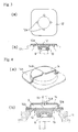
- the top end part of the crankshaft 9 is born on the bearing plate 12 mounted on the top of the housing 11 via the bearing 13 as shown in Fig.3 (b), and as shown in Fig.3 (a), the bearing plate 12 is provided with plural (four) intake ports 12a at regular intervals in the circumferential direction.
- Fig.4 illustrates another embodiment in accordance with the present invention, and as shown in (b), an inversely-dished cover member 14 is mounted on the top of the bearing plate 12 with the lower end square flange part 14b of the cover member 14 fixed to the bearing plate 12, and the cover member 14 not only covers the plural intake ports 12a, but also forms a sealed space S between the bearing plate 12 and the cover member 14, and further, as shown in (a), an introducing opening 14a larger than the intake ports 12a (the diameter is 25-30mm) is arranged at the center on the top of the cover member 14.
- the 3-stage 3-cylinder compressor in accordance with the present invention is constructed as described above, and it is possible to boost the pressure of the gas by compressing it using the gas compression parts sequentially from the 1st stage 1 to the final 3rd stage 3, and discharge a high pressure gas at 30MPa from the discharge pipe 7.
- a 0.5MPa gas is firstly supplied into the housing 11 through the plural intake ports 12a of the bearing plate 12. Thanks to the four pieces of intake ports 12a, the gas is not only decreased in intake pressure loss but increased in an intake gas quantity, and further decreased in pulsation.
- the gas supply source supplies a gas originally at 0.5Mpa
- the gas pressure has been reduced to 0 ⁇ 0.05MPa by arranging a pressure regulator before a conventional 4-stage compressor, however, according to the present invention, it is advantageous that the gas of 0.5MPa can be supplied directly from the gas supply source, and so the pressure regulator is not necessary.
- the gas made to flow into the housing 11 is sucked into the cylinder 1b of the 1st stage gas compression part 1, and compressed to 2MPa and sent into the 2nd stage gas compression part 2 via the 1st communication pipe 5.
- the intake port (a figure omitted) to the cylinder 1b and the discharge port 1c are provided with respective check valves, so that the suction and discharge processes can smoothly be performed.
- the arrangement is the same with the 2nd stage gas compression part 2 and the 3rd stage gas compression part 3.
- the compression gas transferred into the 2nd stage gas compression part 2 is pressurized up to 10MPa. Further, The compression gas pressurized by the 2nd stage compressor 2 is transferred into the 3rd stage compressor 3 and pressurized up to 30MPa.
- the high-pressure gas pressurized by the 3rd stage compressor 3 is discharged from the discharge pipe 7.
- the high-pressure gas discharged from the discharge pipe 7 is filled into a cylinder or the like. In such a manner, it is possible to obtain the same final high-pressure gas of 30MPa even from the 3-cylinder 3-stage compressor as that from a conventional 4-cylinder 4-stage compressor.
- Each compression process from the 1st stage gas compression part 1 to 3rd stage gas compression part 3 is carried out by means of what is called a Scotch yoke mechanism. Namely, the crank pin 10 rotates around the center shaft of the crankshaft 9 synchronizing with the rotation of the crankshaft 9 driven by the electric motor 8, and rotational motion is converted into reciprocating motion via the yokes 4A, 4B engaged with the crank pin 10, and thereby each piston is operated.
- the yokes 4A, 4B are made to be out of phase with each other by 90 degrees as described above, therefore, the compression processes by each gas compression part are shifted in time, and it is possible to compress the gas by sequentially timing from the 1st stage gas compression part 1 to the 3rd stage gas compression part 3.
- the compression process of the 2nd stage gas compression part 2 is provided with the stabilizing pin P and cylinder Q on the opposite side as described above, the arrangement prevents vibration and rattling, to permit stable gas compression.
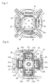
- Fig.5 illustrates an embodiment wherein the present invention is applied to a 4-cylinder single stage compressor, in which a 1st gas compression part 21, a 2nd gas compression part 22, a 3rd gas compression part 23, and a 4th gas compression part 24 are arranged crosswise and opposite to each other.
- the 1st gas compression part 21 has a piston 21a and a cylinder 21b, and the piston 21a is coaxially connected with the piston 23a of the 3rd gas compression part 23 opposed thereto via the yoke 25A, and the cylinder 21b is provided with a discharge opening 21c on the head part.
- the 2nd gas compression part 22 has a piston 22a and a cylinder 22b, and the piston 22a is coaxially connected with the piston 24a of the 4th gas compression part 24 opposed thereto via the yoke 25B shifted out of phase with the yoke 25A by 90 degrees, and the cylinder 22b is provided with a discharge opening 22c on the head part.
- the 3rd gas compression part 23 has a piston 23a and a cylinder 23b, and the piston 23a is attached to the yoke 25A, and the cylinder 23b is provided with a discharge opening 23c on the head part.
- the 1st gas compression part 21 is connected with the 4th gas compression part 24 via a 1st gas transfer pipe 26, and the 1st gas transfer pipe 26 communicates not only with the discharge opening 21c of the 1st gas compression part 21 but also with the path (a figure omitted) in the head part 24c of the 4th gas compression part 24.
- the gas compressed by the 1st gas compression part 21 is transferred into the head part 24d of the 4th gas compression part 24 through the 1st gas transfer pipe 26.
- the 2nd gas compression part 22 is connected with the 4th gas compression part 24 through the 2nd gas transfer pipe 27, and the 3rd gas compression part 23 is connected with the 4th gas compression part 24 through the 3rd gas transfer pipe 28, and thus the gas compressed by the 2nd gas compression part 22 and the gas compressed by the 3rd gas compression part 23 are transferred into the cylinder head part 24d of the 4th gas compression part 24 via the 2nd gas transfer pipe 27 and the 3rd gas transfer pipe 28, respectively.
- the bearing plate 30 mounted on the top of the housing 29 is provided with plural intake ports 30a at regular intervals in the circumferential direction as shown in Fig.5.
- four pieces of intake ports 30a are arranged at the positions corresponding to the 1st gas compression part 21 to 4th gas compression part 24, however, the number or the positions of the intake ports 30a are not restricted to those shown in the figure.
- the 4-cylinder single stage compressor of the structure has the same driving system as the 3-cylinder 3-stage compressor, the former differs from the latter in the point that it has the single stage compression system. Namely, the gas made to flow into the housing 29 from the intake ports 30a is sucked into the 1st gas compression part 21 ⁇ the 4th gas compression part 24 and compressed, respectively, and each compression gas is all transferred and joined into the head part 24d of the 4th gas compression part 24, and discharged from the head part 24d.
- the compression processes with the 1st gas compression part 21 ⁇ the 4th gas compression part 24 are not performed at the same time, but are sequentially performed from the 1st gas compression part 21 to the 4th gas compression part 24.
- the compressed gas from the 1st gas compression part 21 ⁇ the 3rd gas compression part which have already finished the compression processes is transferred into the head part 24d of the 4th gas compression part 24 via the 1st gas transfer pipe 26 ⁇ the 3rd gas transfer pipe 28 before the compression by the 4th gas compression part 24.
- each of the gas compression parts 21-24 can suck a sufficient quantity of gas and can efficiently compress it. Moreover, since each of the gas compression parts 21-24 has the same diameter in this case, it is possible to discharge a large amount of a stable gas compressed at the same compression ratio.
- the present invention it is possible to increase a gas inflow without enlarging a diameter of an intake port by providing the bearing plate with plural gas intake ports in the multi-cylinder compressor. Moreover, the present invention has such excellent advantages as it is possible to connect the compressor with the gas supply source via a single connection pipe by mounting a cover member with an introducing opening on the bearing plate; the cover member acts as an expansion type muffler for muffling the influent gas and further increases the rigidity of the bearing plate; etc.
Landscapes
- Engineering & Computer Science (AREA)
- Mechanical Engineering (AREA)
- General Engineering & Computer Science (AREA)
- Applications Or Details Of Rotary Compressors (AREA)
- Compressors, Vaccum Pumps And Other Relevant Systems (AREA)
- Compressor (AREA)
- Reciprocating Pumps (AREA)
Abstract
Description
Claims (4)
- A multi-cylinder compressor, wherein it is provided with a plurality of gas compression parts comprising pistons and cylinders; a crank shaft for driving the piston of each gas compression part is born by a bearing plate arranged on the top of a housing; and said bearing plate is provided with a intake port, characterized in that said bearing plate is provided with a plurality of intake ports.
- The multi-cylinder compressor as claimed in Claim 1, wherein a cover member provided with a guide port is mounted on the top of said bearing plate, and the plural intake ports are covered with said cover member, and also a sealed space is formed between the cover member and the bearing plate.
- The multi-cylinder compressor as claimed in Claim 1 or 2, wherein the plural gas compression parts are of a multi-stage compression system.
- The multi-cylinder compressor as claimed in Claim 1 or 2, wherein the plural gas compression parts are of a single stage compression system.
Applications Claiming Priority (2)
| Application Number | Priority Date | Filing Date | Title |
|---|---|---|---|
| JP2001102225A JP2002303268A (en) | 2001-03-30 | 2001-03-30 | Multi-cylinder compression device |
| JP2001102225 | 2001-03-30 |
Publications (3)
| Publication Number | Publication Date |
|---|---|
| EP1245830A2 true EP1245830A2 (en) | 2002-10-02 |
| EP1245830A3 EP1245830A3 (en) | 2004-01-21 |
| EP1245830B1 EP1245830B1 (en) | 2005-05-25 |
Family
ID=18955444
Family Applications (1)
| Application Number | Title | Priority Date | Filing Date |
|---|---|---|---|
| EP02007047A Expired - Lifetime EP1245830B1 (en) | 2001-03-30 | 2002-03-27 | Multi-cylinder compressor |
Country Status (7)
| Country | Link |
|---|---|
| US (1) | US6846164B2 (en) |
| EP (1) | EP1245830B1 (en) |
| JP (1) | JP2002303268A (en) |
| KR (1) | KR20020077027A (en) |
| CN (1) | CN1213225C (en) |
| DE (1) | DE60204254T2 (en) |
| TW (1) | TW495582B (en) |
Cited By (2)
| Publication number | Priority date | Publication date | Assignee | Title |
|---|---|---|---|---|
| EP3280914A4 (en) * | 2015-04-09 | 2018-11-14 | Froehler, Anthony Steven | Drive system for chemical injection pumps and instrument air compressors |
| CN114837913A (en) * | 2021-02-02 | 2022-08-02 | 上海海立电器有限公司 | Silencer and compressor |
Families Citing this family (1)
| Publication number | Priority date | Publication date | Assignee | Title |
|---|---|---|---|---|
| CN105065232B (en) * | 2015-09-12 | 2017-11-07 | 浙江鸿友压缩机制造有限公司 | A kind of double-cylinder air compressor intake noise reduction device |
Family Cites Families (9)
| Publication number | Priority date | Publication date | Assignee | Title |
|---|---|---|---|---|
| US2725182A (en) * | 1951-02-01 | 1955-11-29 | David L Spriggs | Air compressor |
| US4190402A (en) * | 1975-05-06 | 1980-02-26 | International Telephone And Telegraph Corporation | Integrated high capacity compressor |
| US4995791A (en) * | 1988-11-25 | 1991-02-26 | Bristol Compressors, Inc. | Refrigerant gas compressor unit |
| EP0378967B1 (en) * | 1989-01-19 | 1993-01-27 | GebràDer Sulzer Aktiengesellschaft | Piston compressor |
| JPH0658244A (en) * | 1992-08-03 | 1994-03-01 | Mitsubishi Heavy Ind Ltd | Fluid pressure pump |
| US5382140A (en) * | 1993-02-11 | 1995-01-17 | Elasis Sistema Ricerca Fiat Nel Mezzogiorno | Radial-piston pump |
| JPH07293440A (en) * | 1994-04-27 | 1995-11-07 | Aisin Seiki Co Ltd | Compressor |
| DE19710379C1 (en) * | 1997-03-13 | 1998-08-20 | Luk Fahrzeug Hydraulik | Suction throttled hydraulic pump for vehicle |
| TW531592B (en) * | 1999-09-09 | 2003-05-11 | Sanyo Electric Co | Multiple stage high pressure compressor |
-
2001
- 2001-03-30 JP JP2001102225A patent/JP2002303268A/en active Pending
- 2001-11-01 TW TW090127129A patent/TW495582B/en not_active IP Right Cessation
- 2001-12-05 KR KR1020010076712A patent/KR20020077027A/en not_active Ceased
- 2001-12-14 CN CNB011436352A patent/CN1213225C/en not_active Expired - Fee Related
-
2002
- 2002-03-27 EP EP02007047A patent/EP1245830B1/en not_active Expired - Lifetime
- 2002-03-27 DE DE60204254T patent/DE60204254T2/en not_active Expired - Fee Related
- 2002-03-29 US US10/113,914 patent/US6846164B2/en not_active Expired - Fee Related
Cited By (3)
| Publication number | Priority date | Publication date | Assignee | Title |
|---|---|---|---|---|
| EP3280914A4 (en) * | 2015-04-09 | 2018-11-14 | Froehler, Anthony Steven | Drive system for chemical injection pumps and instrument air compressors |
| US10753544B2 (en) | 2015-04-09 | 2020-08-25 | Anthony Steven Froehler | Drive system for chemical injection pumps and instrument air compressors |
| CN114837913A (en) * | 2021-02-02 | 2022-08-02 | 上海海立电器有限公司 | Silencer and compressor |
Also Published As
| Publication number | Publication date |
|---|---|
| US6846164B2 (en) | 2005-01-25 |
| EP1245830A3 (en) | 2004-01-21 |
| CN1213225C (en) | 2005-08-03 |
| CN1379181A (en) | 2002-11-13 |
| EP1245830B1 (en) | 2005-05-25 |
| TW495582B (en) | 2002-07-21 |
| JP2002303268A (en) | 2002-10-18 |
| DE60204254D1 (en) | 2005-06-30 |
| US20020155006A1 (en) | 2002-10-24 |
| KR20020077027A (en) | 2002-10-11 |
| DE60204254T2 (en) | 2006-01-26 |
Similar Documents
| Publication | Publication Date | Title |
|---|---|---|
| US8047810B2 (en) | Double-headed piston type compressor | |
| KR100772779B1 (en) | Reciprocal movement compressor | |
| US5674054A (en) | Reciprocating type compressor | |
| US8419380B2 (en) | Hermetic compressor | |
| US20090016917A1 (en) | Compact Dual Rocking Piston Pump with Reduced Number of Parts | |
| KR100235512B1 (en) | Muffler Structure of Compressor | |
| CN1102698C (en) | Double headed piston type compressor | |
| JP4347684B2 (en) | Horizontally opposed compressor | |
| US5281104A (en) | Sequential displacement piston pump | |
| EP1245830B1 (en) | Multi-cylinder compressor | |
| US20040018106A1 (en) | Compressor and method with an improved inlet and discharge valve arrangement | |
| US6626648B1 (en) | Apparatus for noise depreciating in hermetic compressor | |
| JP2001280234A (en) | Opposed reciprocating pump | |
| JP4241088B2 (en) | Crankshaft bearing structure of multi-cylinder compressor | |
| JP2004257346A (en) | Piping structure for multicylinder single-stage compressor | |
| JP2004257350A (en) | Multicylinder single-stage compressor | |
| CN121184334A (en) | Multi-piston air compressors and their applications | |
| JP2003517534A (en) | Multi-piston engine such as pump or compressor with improved vibration behavior | |
| KR19990024202U (en) | Air compressor | |
| JP2004257348A (en) | Multicylinder compressor | |
| JP2002039063A (en) | Reciprocating compressor | |
| JP2003129856A (en) | Auxiliary equipment mounting structure | |
| CN209083402U (en) | The air compressor and engine of engine | |
| JP2000274357A (en) | Multistage compression device | |
| JPH05272459A (en) | Bellows type compressor |
Legal Events
| Date | Code | Title | Description |
|---|---|---|---|
| PUAI | Public reference made under article 153(3) epc to a published international application that has entered the european phase |
Free format text: ORIGINAL CODE: 0009012 |
|
| AK | Designated contracting states |
Kind code of ref document: A2 Designated state(s): AT BE CH CY DE DK ES FI FR GB GR IE IT LI LU MC NL PT SE TR |
|
| AX | Request for extension of the european patent |
Free format text: AL;LT;LV;MK;RO;SI |
|
| PUAL | Search report despatched |
Free format text: ORIGINAL CODE: 0009013 |
|
| AK | Designated contracting states |
Kind code of ref document: A3 Designated state(s): AT BE CH CY DE DK ES FI FR GB GR IE IT LI LU MC NL PT SE TR |
|
| AX | Request for extension of the european patent |
Extension state: AL LT LV MK RO SI |
|
| RIC1 | Information provided on ipc code assigned before grant |
Ipc: 7F 04B 25/00 B Ipc: 7F 04B 39/12 A |
|
| 17P | Request for examination filed |
Effective date: 20040322 |
|
| 17Q | First examination report despatched |
Effective date: 20040421 |
|
| AKX | Designation fees paid |
Designated state(s): DE GB IT |
|
| GRAP | Despatch of communication of intention to grant a patent |
Free format text: ORIGINAL CODE: EPIDOSNIGR1 |
|
| GRAS | Grant fee paid |
Free format text: ORIGINAL CODE: EPIDOSNIGR3 |
|
| GRAA | (expected) grant |
Free format text: ORIGINAL CODE: 0009210 |
|
| AK | Designated contracting states |
Kind code of ref document: B1 Designated state(s): DE GB IT |
|
| REG | Reference to a national code |
Ref country code: GB Ref legal event code: FG4D |
|
| REG | Reference to a national code |
Ref country code: IE Ref legal event code: FG4D |
|
| REF | Corresponds to: |
Ref document number: 60204254 Country of ref document: DE Date of ref document: 20050630 Kind code of ref document: P |
|
| PLBE | No opposition filed within time limit |
Free format text: ORIGINAL CODE: 0009261 |
|
| STAA | Information on the status of an ep patent application or granted ep patent |
Free format text: STATUS: NO OPPOSITION FILED WITHIN TIME LIMIT |
|
| 26N | No opposition filed |
Effective date: 20060228 |
|
| PGFP | Annual fee paid to national office [announced via postgrant information from national office to epo] |
Ref country code: GB Payment date: 20090325 Year of fee payment: 8 |
|
| PGFP | Annual fee paid to national office [announced via postgrant information from national office to epo] |
Ref country code: DE Payment date: 20090319 Year of fee payment: 8 Ref country code: IT Payment date: 20090317 Year of fee payment: 8 |
|
| GBPC | Gb: european patent ceased through non-payment of renewal fee |
Effective date: 20100327 |
|
| PG25 | Lapsed in a contracting state [announced via postgrant information from national office to epo] |
Ref country code: DE Free format text: LAPSE BECAUSE OF NON-PAYMENT OF DUE FEES Effective date: 20101001 |
|
| PG25 | Lapsed in a contracting state [announced via postgrant information from national office to epo] |
Ref country code: IT Free format text: LAPSE BECAUSE OF NON-PAYMENT OF DUE FEES Effective date: 20100327 Ref country code: GB Free format text: LAPSE BECAUSE OF NON-PAYMENT OF DUE FEES Effective date: 20100327 |