EP1245803A1 - Internal combustion engine with variable compression ratio - Google Patents
Internal combustion engine with variable compression ratio Download PDFInfo
- Publication number
- EP1245803A1 EP1245803A1 EP01201203A EP01201203A EP1245803A1 EP 1245803 A1 EP1245803 A1 EP 1245803A1 EP 01201203 A EP01201203 A EP 01201203A EP 01201203 A EP01201203 A EP 01201203A EP 1245803 A1 EP1245803 A1 EP 1245803A1
- Authority
- EP
- European Patent Office
- Prior art keywords
- gearbox
- crankshaft
- eccentrics
- engine block
- engine
- Prior art date
- Legal status (The legal status is an assumption and is not a legal conclusion. Google has not performed a legal analysis and makes no representation as to the accuracy of the status listed.)
- Withdrawn
Links
Images


Classifications
-
- F—MECHANICAL ENGINEERING; LIGHTING; HEATING; WEAPONS; BLASTING
- F02—COMBUSTION ENGINES; HOT-GAS OR COMBUSTION-PRODUCT ENGINE PLANTS
- F02B—INTERNAL-COMBUSTION PISTON ENGINES; COMBUSTION ENGINES IN GENERAL
- F02B75/00—Other engines
- F02B75/04—Engines with variable distances between pistons at top dead-centre positions and cylinder heads
- F02B75/047—Engines with variable distances between pistons at top dead-centre positions and cylinder heads by means of variable crankshaft position
Definitions
- the invention relates to an internal combustion engine with variable compression ratio according to the preamble of claim 1.
- An engine of this type is for example known from US patent 5,605,120.
- the engine block is supported by a frame in an adjustable manner, such that upon relative repositioning of the crankshaft centerline and the engine block, it is the engine block that is repositioned with respect to the frame.
- all kinds of co-operating parts such as for example the exhaust, waterhoses, electrical wiring etc., must be able to adopt or absorb this movements. This makes the engine complex.
- the object of the present invention is to provide an improved internal combustion engine with variable compression ratio.
- the internal combustion engine according to the invention has the features of the characterising portion of claim 1.
- the engine block can be kept stationary and it is the gearbox that is moving in order to keep the crankshaft and the gearbox input shaft in alignment.
- the movement of gearbox is easier to adopt, since the output shaft of the gearbox or the drive shafts of the differential can more easily be adapted to movements of the gearbox than, for example the exhaust, to movements of the engine block.
- the eccentrics have a gearbox flange outside the engine block, said gearbox flange having the same eccentricity as the eccentrics and supporting the gearbox through a bearing.
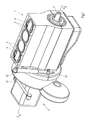
- Fig. 1 is a perspective view of an engine block and gearbox of a first embodiment of the internal combustion engine according to the invention.
- Fig. 2 is a sectional view along the line II-II in fig. 1, on a larger scale.
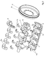
- Fig. 3 is a perspective exploded view of the crankshaft and eccentric bearings from the engine according to fig. 2.
- Fig. 4a is a perspective side view of a part of the engine of fig. 2, partly cut away, and shown in a position of the eccentrics to effect a minimum compression ratio.
- Fig. 4b is a front view according to arrow IV in fig. 4a.
- Figs. 5a, 5b and 6a, 6b are views corresponding to those of fig. 4a, 4b, but shown in a position effecting medium compression ratio and a position effecting maximum compression ratio.
- Fig. 7 is a view corresponding to that of fig. 2 and showing a second embodiment of the engine according to the invention.
- Fig. 8 is a perspective exploded view of the crankshaft and eccentrics from the engine of Fig. 7.
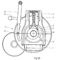
- Figs. 9 and 10 illustrate the effect of the double eccentrics in the embodiment of Fig. 7 and 8.
- FIG. 1 show that the engine in the first embodiment is a four cylinder in-line engine having four cylinders 3 and four pistons 4 reciprocating therein.
- a crankshaft 5 is rotatably mounted within the engine block 1 to convert the reciprocating movement of the pistons 4 into a rotating movement.
- the crankshaft 5 has four cranks 6 each rotatably supporting a piston rod 7 rotatably connected at the opposite, upper end to the respective piston 4.
- the stroke of each piston 4 within its cylinder 3 is determined by the radius of the centerline of the cranks 6 with respect to the centerline or axis of rotation 8 of the crankshaft 5.
- the stroke is two times this radius and since the radius is fixed, the stroke of the pistons 4 is fixed as well.
- the end positions of the stroke depend on the position of the centerline 8 of the crankshaft 5 and if the position of this centerline is changed, the upper and lower dead center will change as well.
- This repositioning of the crankshaft centerline 8 can be used to obtain a variable compression ratio.
- the compression ratio is the ratio between the volume of the cylinder 3 above the piston 4 in its lower dead center and the volume of the cylinder above the piston in its upper dead center. Moving the centerline 8 of the crank shaft 5 away from the cylinders 3 will lead to a lower compression ratio, whereas the compression ratio will be increased when the centerline 8 of the crank shaft 5 is moved towards the cylinders 3.
- FIG. 3 shows the structure of the bearings 9 and eccentrics 10.
- the crankshaft 5 has five main bearings 9 consisting of slide bearings formed by upper bearing cups 9a and lower bearing cups 9b.
- the eccentrics 10 are constructed as bushes formed from two halves, the lower bush halves 10b being integrated in a eccentric assembly 11, whereas the upper bush halves 10a are separate halve bushes which are fixed to the lower bush halves 10b by fasteners such as bolts or screws.
- the lower bush halves 10b are interconnected by shells such that the crankwebs of the crankshaft rotate inside them.
- the upper bearing cups 9a are of normal width, whereas the lower bearing cups 9b are of smaller width in order to create room for the shells.
- These shells are cut away at 30° on their upper side to enable a rotation of the eccentric assembly 11 of +/- 30°.
- the eccentrics or bushes 10 have an eccentricity of a few millimeters, for example 5mm.
- the horizontal and vertical position of the bearings 9 within the eccentrics 10, and therefore of the crankshaft centerline 8 is changed. This will be further explained later-on with reference to figures 4-6.
- the maximum rotation of the eccentrics is 60°, i.e. 30° in each direction from the central position.
- the crankshaft 5 has on one end a flywheel or crankshaft flange 12 to fix the crankshaft to the gears of the gearbox, in this case through a flywheel 13 and a coupling 14, which connects to an input shaft 15 of the gearbox which is not further shown.
- the gear box 2 changes its position as well such that the input shaft 15 of the gear box is kept aligned with the crankshaft 5.
- the gearbox 2 is moveably connected to the engine block 1 such that the gearbox is repositioned simultaneously with a repositioning of the crank shaft 5.
- the eccentric assembly 11 has a flange 16 to which a gearbox flange 17 is mounted and this flange 17 has a rim 18 which has the same eccentricity as the eccentrics 10 and is positioned in a manner to keep the input gearbox input shaft 15 in line with the crankshaft 5.
- the rim 18 supports the gearbox 2 through a large roller bearing 19.
- the gearbox flange 17 has an additional support in the engine block 1 through a roller bearing 20.
- reaction rod 21 In order to prevent the gearbox 2 from rotating together with the crankshaft 5 or together with the gearbox flange 17, there is provided a reaction rod 21. This is positioned substantially horizontally (or substantially perpendicularly to the plane of symmetry through the cylinders 3) and connects to the gearbox 2 at the position outside the centerline. The other end of the reaction rod 21 is mounted to a fixed part of the vehicle or to a part fixed to the engine block 1.
- the purpose of the variation of the compression ratio is to adapt the compression ratio to the engine conditions, as load, rotational speed and the like, in order to improve the efficiency of the engine.
- the eccentrics 10 are adjusted by an external adjustment member in the form of a hydraulic cylinder 22 controlled by the electronic control system and connected to the gearbox flange 17 through a slot 23 in the gearbox or flywheel housing.
- the slot has a length of arc of 60°.
- the hydraulic cylinder 22 is connected at its other end to the cylinder head of the engine block, for example.
- the eccentrics 10 are positioned such that the compression ratio is at a minimum. It is clearly shown in fig. 4a that the adjustment member 22 is in its top position wherein the eccentrics are rotated 30° from the central position such that the crankshaft 5 is moved downwardly from this central position. Thus, the crankshaft is in its lowest position so that the piston 4 has its lowest top dead center and therefore a minimum compression ratio. As is shown fig. 4b, the rim 18 of the gearbox flange 17 is also in a low position in which the input shaft 15 is aligned with the crankshaft 5. In fig. 5a and 5b the adjustment member 22 is in its central position, which is also true for the crankshaft 5, the piston 4 and the rim 18 of the gearbox flange 17.
- the adjustment member 22 is in a downward position, the eccentrics 10 being rotated 30° in a direction in which the crankshaft 5 is displaced upwardly.
- the piston can reach the highest top dead center and the compression ratio is then at a maximum.
- the gearbox 2 has moved correspondingly.
- crankshaft 5 and the gearbox 2 do not move in a straight line but follow a curved path.
- the central position of the eccentrics is chosen such that the horizontal displacement is at a minimum in relation to the vertical displacement. The horizontal displacement does not have a detrimental effect on the dynamics of the crankshaft-piston mechanism.
- Figs. 7 and 8 show a second embodiment of the internal combustion engine having a variable compression ratio.
- the invention is used in an engine in which the cylinders are positioned in a V-shape.
- it is a V8 engine with two piston rods positioned on each crank 6 of the crankshaft 5.
- it is important that the centerline 8 of the crankshaft 5 moves in the center plane C (see Figs. 9 and 10) of the cylinder banks in order to obtain the same compression ratio in each cylinder (in all eccentric positions of the crankshaft 5).
- the eccentrics 10 are supported by second eccentrics 24 which have the same eccentricity (in mirror image) as the eccentrics 10, but are adjusted or rotated in opposite direction. In this way, the movements of the eccentrics 10, 24 in a direction perpendicular to the center plane are neutralized, whereas the displacements within the center plane are added.
- the opposite rotation of both eccentrics 10 and 24 can be obtained by two mechanically or electronically synchronized adjustment members, or by some kind of connection member between both eccentrics 10 and 24 reversing the rotation of one eccentric 10 into an opposite rotation of the other one.
- Fig. 8 shows that the eccentrics 24 are formed of lower bush halves 24b integrated in a eccentric assembly 26 and separate upper bush halves 24a fixed to the lower bush halves 24b. The whole assembly could be introduced into the engine block through a side opening of the engine block.
- the centerline of the rim 18 is again aligned with the centerline 8 of the crankshaft 5.
- the gearbox flange 17 though is now supported by the second eccentric assembly 26 via the support flange 25. Because the second eccentric assembly is a very rigid structure, it is not necessary to support the second eccentric assembly 26 by the engine block 1.
- Figs. 9 and 10 illustrate two extreme positions of the eccentrics 10 and 24, and consequently of the top dead center of the pistons 4.
- the adjustment member could also be arranged internally, for instance in the oil sump.
- the adjustment member may be a hydraulic cylinder or an electric motor, such as a stepping motor connected to the eccentric assembly through a worm wheel drive or the like.
Landscapes
- Engineering & Computer Science (AREA)
- Chemical & Material Sciences (AREA)
- Combustion & Propulsion (AREA)
- Mechanical Engineering (AREA)
- General Engineering & Computer Science (AREA)
- Output Control And Ontrol Of Special Type Engine (AREA)
- Shafts, Cranks, Connecting Bars, And Related Bearings (AREA)
Abstract
The invention relates to an internal combustion engine,
which comprises a engine block (1) with at least one cylinder
(3), and a crankshaft (5) having at least a crank (6) and being
rotatably supported within the engine block. The piston (4) is
reciprocated within the cylinder and has a piston rod (6)
mounted to the piston on one end and mounted to the crank of the
crankshaft on the other end. The crankshaft (5) is journalled on
bearings (9) which are mounted in adjustable eccentrics (10),
rotation of the eccentrics causing relative repositioning of the
crankshaft centerline (8) and the engine block (1) in order to
adjust the compression ratio of the piston in its cylinder. The
engine further comprises a gearbox (2) having an input shaft
(15) connected to the crankshaft (5). The gearbox (2) and the
engine block (1) are mounted to each other in such manner that
the engine block and gearbox are relatively repositioned
simultaneously with a crankshaft repositioning. The engine block
(1) is substantially stationary and the gearbox (2) is
operatively coupled to the eccentrics (10) such that the gearbox
input shaft (15) is kept aligned with the crankshaft (5) when
this crankshaft is repositioned. The gearbox has means (21) to
prevent rotation of the gearbox relative to the engine block.
Description
- The invention relates to an internal combustion engine with variable compression ratio according to the preamble of
claim 1. - An engine of this type is for example known from US patent 5,605,120. In this prior art engine, the engine block is supported by a frame in an adjustable manner, such that upon relative repositioning of the crankshaft centerline and the engine block, it is the engine block that is repositioned with respect to the frame. This means that the engine block should be mounted in the vehicle in a movable manner. The problem is then that all kinds of co-operating parts, such as for example the exhaust, waterhoses, electrical wiring etc., must be able to adopt or absorb this movements. This makes the engine complex.
- The object of the present invention is to provide an improved internal combustion engine with variable compression ratio.
- For this purpose, the internal combustion engine according to the invention has the features of the characterising portion of
claim 1. - According to the invention, the engine block can be kept stationary and it is the gearbox that is moving in order to keep the crankshaft and the gearbox input shaft in alignment. The movement of gearbox is easier to adopt, since the output shaft of the gearbox or the drive shafts of the differential can more easily be adapted to movements of the gearbox than, for example the exhaust, to movements of the engine block.
- In one embodiment of the engine, the eccentrics have a gearbox flange outside the engine block, said gearbox flange having the same eccentricity as the eccentrics and supporting the gearbox through a bearing.
- In this way, the movement of the eccentrics and the gearbox is synchronised mechanically so that the crankshaft and the input shaft of the gearbox remain in line.
- Further advantageous embodiments are subject of dependent claims.
- The invention will hereafter be explained in more detail with reference to the drawings, showing embodiments of the engine according to the invention by way of example.
- Fig. 1 is a perspective view of an engine block and gearbox of a first embodiment of the internal combustion engine according to the invention.
- Fig. 2 is a sectional view along the line II-II in fig. 1, on a larger scale.
- Fig. 3 is a perspective exploded view of the crankshaft and eccentric bearings from the engine according to fig. 2.
- Fig. 4a is a perspective side view of a part of the engine of fig. 2, partly cut away, and shown in a position of the eccentrics to effect a minimum compression ratio.
- Fig. 4b is a front view according to arrow IV in fig. 4a.
- Figs. 5a, 5b and 6a, 6b are views corresponding to those of fig. 4a, 4b, but shown in a position effecting medium compression ratio and a position effecting maximum compression ratio.
- Fig. 7 is a view corresponding to that of fig. 2 and showing a second embodiment of the engine according to the invention.
- Fig. 8 is a perspective exploded view of the crankshaft and eccentrics from the engine of Fig. 7.
- Figs. 9 and 10 illustrate the effect of the double eccentrics in the embodiment of Fig. 7 and 8.
- The drawings show embodiments of an internal combustion engine comprising an
engine block 1 and agearbox 2 mounted thereto. If the engine is used in a vehicle having front wheel drive, the gearbox also includes the differential with the drive shafts for the front wheel axles. The gearbox housing also includes a flywheel housing. The engine can be of the Diesel or Otto type. Figs. 1 and 2 show that the engine in the first embodiment is a four cylinder in-line engine having fourcylinders 3 and fourpistons 4 reciprocating therein. Acrankshaft 5 is rotatably mounted within theengine block 1 to convert the reciprocating movement of thepistons 4 into a rotating movement. Thecrankshaft 5 has fourcranks 6 each rotatably supporting apiston rod 7 rotatably connected at the opposite, upper end to therespective piston 4. - The stroke of each
piston 4 within itscylinder 3 is determined by the radius of the centerline of thecranks 6 with respect to the centerline or axis ofrotation 8 of thecrankshaft 5. The stroke is two times this radius and since the radius is fixed, the stroke of thepistons 4 is fixed as well. However, the end positions of the stroke depend on the position of thecenterline 8 of thecrankshaft 5 and if the position of this centerline is changed, the upper and lower dead center will change as well. This repositioning of thecrankshaft centerline 8 can be used to obtain a variable compression ratio. The compression ratio is the ratio between the volume of thecylinder 3 above thepiston 4 in its lower dead center and the volume of the cylinder above the piston in its upper dead center. Moving thecenterline 8 of thecrank shaft 5 away from thecylinders 3 will lead to a lower compression ratio, whereas the compression ratio will be increased when thecenterline 8 of thecrank shaft 5 is moved towards thecylinders 3. - The repositioning of the
crankshaft centerline 8 is effected by having thecrank shaft 5 journalled inbearings 9 which are accommodated ineccentrics 10. Fig. 3 shows the structure of thebearings 9 andeccentrics 10. Thecrankshaft 5 has fivemain bearings 9 consisting of slide bearings formed by upper bearingcups 9a and lower bearingcups 9b. Theeccentrics 10 are constructed as bushes formed from two halves, thelower bush halves 10b being integrated in aeccentric assembly 11, whereas theupper bush halves 10a are separate halve bushes which are fixed to thelower bush halves 10b by fasteners such as bolts or screws. Thelower bush halves 10b are interconnected by shells such that the crankwebs of the crankshaft rotate inside them. As the shells are only provided at the lower side, the upper bearingcups 9a are of normal width, whereas thelower bearing cups 9b are of smaller width in order to create room for the shells. These shells are cut away at 30° on their upper side to enable a rotation of theeccentric assembly 11 of +/- 30°. - The eccentrics or
bushes 10 have an eccentricity of a few millimeters, for example 5mm. By rotation of theseeccentrics 10 in their bearings in theengine block 1, the horizontal and vertical position of thebearings 9 within theeccentrics 10, and therefore of thecrankshaft centerline 8 is changed. This will be further explained later-on with reference to figures 4-6. In the embodiment as shown, the maximum rotation of the eccentrics is 60°, i.e. 30° in each direction from the central position. - The
crankshaft 5 has on one end a flywheel orcrankshaft flange 12 to fix the crankshaft to the gears of the gearbox, in this case through aflywheel 13 and acoupling 14, which connects to aninput shaft 15 of the gearbox which is not further shown. - As the position of the
crankshaft centerline 8 relative to the engine block changes upon rotation of theeccentrics 10, it is necessary that thegear box 2 changes its position as well such that theinput shaft 15 of the gear box is kept aligned with thecrankshaft 5. For this purpose, thegearbox 2 is moveably connected to theengine block 1 such that the gearbox is repositioned simultaneously with a repositioning of thecrank shaft 5. - In order to effect this, the
eccentric assembly 11 has aflange 16 to which agearbox flange 17 is mounted and thisflange 17 has arim 18 which has the same eccentricity as theeccentrics 10 and is positioned in a manner to keep the inputgearbox input shaft 15 in line with thecrankshaft 5. Therim 18 supports thegearbox 2 through a large roller bearing 19. Thegearbox flange 17 has an additional support in theengine block 1 through a roller bearing 20. - In order to prevent the
gearbox 2 from rotating together with thecrankshaft 5 or together with thegearbox flange 17, there is provided areaction rod 21. This is positioned substantially horizontally (or substantially perpendicularly to the plane of symmetry through the cylinders 3) and connects to thegearbox 2 at the position outside the centerline. The other end of thereaction rod 21 is mounted to a fixed part of the vehicle or to a part fixed to theengine block 1. - The purpose of the variation of the compression ratio is to adapt the compression ratio to the engine conditions, as load, rotational speed and the like, in order to improve the efficiency of the engine. This means that the compression ratio should be varied continuously and should be controlled by an electronic control system which measures said conditions as input variables. In this embodiment, the
eccentrics 10 are adjusted by an external adjustment member in the form of ahydraulic cylinder 22 controlled by the electronic control system and connected to thegearbox flange 17 through aslot 23 in the gearbox or flywheel housing. The slot has a length of arc of 60°. Thehydraulic cylinder 22 is connected at its other end to the cylinder head of the engine block, for example. - In figures 4, 5 and 6 the operation of the invention is illustrated.
- In fig. 4a and 4b, the
eccentrics 10 are positioned such that the compression ratio is at a minimum. It is clearly shown in fig. 4a that theadjustment member 22 is in its top position wherein the eccentrics are rotated 30° from the central position such that thecrankshaft 5 is moved downwardly from this central position. Thus, the crankshaft is in its lowest position so that thepiston 4 has its lowest top dead center and therefore a minimum compression ratio. As is shown fig. 4b, therim 18 of thegearbox flange 17 is also in a low position in which theinput shaft 15 is aligned with thecrankshaft 5. In fig. 5a and 5b theadjustment member 22 is in its central position, which is also true for thecrankshaft 5, thepiston 4 and therim 18 of thegearbox flange 17. - In fig. 6a and 6b, the
adjustment member 22 is in a downward position, theeccentrics 10 being rotated 30° in a direction in which thecrankshaft 5 is displaced upwardly. Thus, the piston can reach the highest top dead center and the compression ratio is then at a maximum. Thegearbox 2 has moved correspondingly. - It is noted that the
crankshaft 5 and thegearbox 2 do not move in a straight line but follow a curved path. However, the central position of the eccentrics is chosen such that the horizontal displacement is at a minimum in relation to the vertical displacement. The horizontal displacement does not have a detrimental effect on the dynamics of the crankshaft-piston mechanism. - Figs. 7 and 8 show a second embodiment of the internal combustion engine having a variable compression ratio. In this embodiment, the invention is used in an engine in which the cylinders are positioned in a V-shape. In this case it is a V8 engine with two piston rods positioned on each crank 6 of the
crankshaft 5. In this embodiment it is important that thecenterline 8 of thecrankshaft 5 moves in the center plane C (see Figs. 9 and 10) of the cylinder banks in order to obtain the same compression ratio in each cylinder (in all eccentric positions of the crankshaft 5). In order to have the crankshaft displaced within the center plane, theeccentrics 10 are supported bysecond eccentrics 24 which have the same eccentricity (in mirror image) as theeccentrics 10, but are adjusted or rotated in opposite direction. In this way, the movements of theeccentrics eccentrics eccentrics - Fig. 8 shows that the
eccentrics 24 are formed of lower bush halves 24b integrated in aeccentric assembly 26 and separate upper bush halves 24a fixed to thelower bush halves 24b. The whole assembly could be introduced into the engine block through a side opening of the engine block. - The centerline of the
rim 18 is again aligned with thecenterline 8 of thecrankshaft 5. Thegearbox flange 17 though is now supported by the secondeccentric assembly 26 via thesupport flange 25. Because the second eccentric assembly is a very rigid structure, it is not necessary to support the secondeccentric assembly 26 by theengine block 1. - Figs. 9 and 10 illustrate two extreme positions of the
eccentrics pistons 4. - According to the invention there is obtained an easy adjustment of the compression ratio, whereas the proper alignment of the crankshaft and the input shaft of the gearbox is maintained in a relatively simple manner. The movements of the gearbox with respect to the engine block can be adopted easily by the output shaft of the gearbox (or drive shafts of the differential), since it will include a cardan joint anyhow. The engine block can remain stationary. The reaction rod to prevent rotation of the gearbox can be used to measure the torque of the engine.
- The invention is not restricted to the embodiments described above and shown in the drawing, which may be varied in different ways within the scope of the invention. For example, the adjustment member could also be arranged internally, for instance in the oil sump. The adjustment member may be a hydraulic cylinder or an electric motor, such as a stepping motor connected to the eccentric assembly through a worm wheel drive or the like.
Claims (15)
- Internal combustion engine, comprising a engine block (1) with at least one cylinder (3), a crankshaft (5) having at least a crank (6) and being rotatably supported within the engine block, at least one piston (4) reciprocable within the cylinder and having a piston rod (6) mounted to the piston on one end and mounted to the crank of the crankshaft on the other end, said crankshaft (5) being journalled on bearings (9) which are mounted in adjustable eccentrics (10), rotation of the eccentrics causing relative repositioning of the crankshaft centerline (8) and the engine block (1) in order to adjust the compression ratio of the piston in its cylinder, the engine further comprising a gearbox (2) having an input shaft (15) connected to the crankshaft (5), the gearbox (2) and the engine block (1) being mounted to each other in such manner that the engine block and gearbox are relatively repositioned simultaneously with a crankshaft repositioning, characterized in that the engine block (1) is substantially stationary and the gearbox (2) is operatively coupled to the eccentrics (10) such that the gearbox input shaft (15) is kept aligned with the crankshaft (5) when this crankshaft is repositioned, the gearbox having means (21) to prevent rotation of the gearbox relative to the engine block.
- Engine according to claim 1, wherein the eccentrics (10) have a gearbox flange (17) outside the engine block (1), said gearbox flange having the same eccentricity as the eccentrics and supporting the gearbox through a bearing (19).
- Engine according to claim 2, wherein the gearbox flange (17) is supported externally by the engine block through a roller bearing (20).
- Engine according to one of the preceding claims, wherein the eccentrics (10) comprise bushes journalled in a wall of the engine block (1) and including a crankshaft bearing (19) which is positioned eccentrically with respect to the bush centerline.
- Engine according to claim 4, wherein the eccentrics (10) comprise two bushes, one on each side of the crank (6), said bushes being connected in a eccentric assembly (11) dimensioned and positioned so as to leave room for the piston rod (7).
- Engine according to claim 4 or 5, wherein the crankshaft (5) is an integral part, whereas the eccentrics comprise a half shell containing integrated first bush halves (10b) and further comprise separate second bush halves (10a) attached to the first bush halves to form the bushes.
- Engine according to one of the preceding claims, wherein the engine block (1) comprises at least two cylinders (3) positioned in-line.
- Engine according to one of the preceding claims, wherein the eccentrics (10) are adjustable by means of an electronically controlled adjustment member (22).
- Engine according to claim 8, wherein the adjustment member (22) is a hydraulic cylinder engaging a part which is connected to the eccentrics (10).
- Engine according to claim 8 or 9, wherein the adjustment member (22) is mounted to the outside of the engine block (1) and engages the part connected to the eccentrics (10) through a hole in the wall of the engine block or gearbox (2).
- Engine according to claim 10, wherein the adjustment member (22) engages the gearbox flange (17) connected to the eccentrics (10).
- Engine according to claim 8, wherein the adjustment member is mounted internally of the engine block (1) and is preferably an electric motor, such as a stepping motor.
- Engine according to one of the preceding claims, wherein the means (21) to prevent rotation of the gearbox (2) includes a reaction rod engaging the gearbox outside the center and preferably extending in a direction substantially perpendicularly to the cylinder (3) of the engine block (1).
- Engine according to one of the preceding claims, wherein the engine block (1) comprises at least two cylinders (3) positioned in V-shape having a center plane, the eccentrics (10) being rotatably supported by second eccentrics (24) having the same eccentricity but being adjusted in opposite direction, such that the eccentricities are a mirror image with respect to the center plane.
- Internal combustion engine, comprising a engine block (1) with at least two cylinders (3), a crankshaft (5) having at least one crank (6) and being rotatably supported within the engine block, at least two pistons (4) reciprocable within their respective cylinder and having a piston rod (6) mounted to the piston on one end and mounted to the at least one crank of the crankshaft on the other end, said crankshaft (5) being journalled on bearings (9) which are mounted in adjustable eccentrics (10), rotation of the eccentrics causing relative repositioning of the crankshaft centerline (8) and the engine block (1) in order to adjust the compression ratio of the pistons in their cylinder, the engine further comprising a gearbox (2) having an input shaft (15) connected to the crankshaft (5), the gearbox (2) and the engine block (1) being mounted to each other in such manner that the engine block and gearbox are relatively repositioned simultaneously with a crankshaft repositioning, characterized in that the cylinders (3) of the engine are positioned in a V-shape having a center plane, wherein adjustable eccentrics (10) are supported by second eccentrics (24) having the same eccentricity as the first eccentrics (10) and being adjusted simultaneously with the first eccentrics, but in opposite direction, such that the eccentricities form a mirror image with respect to the center plane of the V-shape.
Priority Applications (3)
| Application Number | Priority Date | Filing Date | Title |
|---|---|---|---|
| EP01201203A EP1245803A1 (en) | 2001-03-30 | 2001-03-30 | Internal combustion engine with variable compression ratio |
| US10/473,609 US20040168657A1 (en) | 2001-03-30 | 2002-03-27 | Internal combustion engine with variable compression ratio |
| PCT/EP2002/003525 WO2002079626A1 (en) | 2001-03-30 | 2002-03-27 | Internal combustion engine with variable compression ratio |
Applications Claiming Priority (1)
| Application Number | Priority Date | Filing Date | Title |
|---|---|---|---|
| EP01201203A EP1245803A1 (en) | 2001-03-30 | 2001-03-30 | Internal combustion engine with variable compression ratio |
Publications (1)
| Publication Number | Publication Date |
|---|---|
| EP1245803A1 true EP1245803A1 (en) | 2002-10-02 |
Family
ID=8180093
Family Applications (1)
| Application Number | Title | Priority Date | Filing Date |
|---|---|---|---|
| EP01201203A Withdrawn EP1245803A1 (en) | 2001-03-30 | 2001-03-30 | Internal combustion engine with variable compression ratio |
Country Status (3)
| Country | Link |
|---|---|
| US (1) | US20040168657A1 (en) |
| EP (1) | EP1245803A1 (en) |
| WO (1) | WO2002079626A1 (en) |
Cited By (9)
| Publication number | Priority date | Publication date | Assignee | Title |
|---|---|---|---|---|
| DE102004051012A1 (en) * | 2004-10-20 | 2006-04-27 | Daimlerchrysler Ag | Lifting cylinder internal combustion engine with variable compression has two mass flywheel with its primary winding connected to the crankshaft and secondary winding connected to transmission |
| US7370613B2 (en) * | 2004-11-30 | 2008-05-13 | Caterpillar Inc. | Eccentric crank variable compression ratio mechanism |
| WO2009083023A1 (en) * | 2007-12-31 | 2009-07-09 | Fev Motorentechnik Gmbh | Parallel crank drive |
| DE102008005467A1 (en) * | 2008-01-21 | 2009-07-23 | Fev Motorentechnik Gmbh | Reciprocating piston engine has eccentrically stored and adjusted crankshaft and detection device of one or multiple effective eccentric moments |
| DE102008050826A1 (en) * | 2008-10-08 | 2010-04-15 | Schaeffler Kg | Adjusting device for changing position of crankshaft to adjust variable compression ratio of petrol engine, has rotation drive with lever coupled with adjusting shaft, where drive is designed as motor with actuator and reduction stage |
| US20100282217A1 (en) * | 2007-12-31 | 2010-11-11 | Fev Motorentechnik Gmbh | Vcr universal drive |
| US20100326404A1 (en) * | 2009-06-30 | 2010-12-30 | Hyundai Motor Company | Variable compression ratio apparatus |
| WO2011069569A1 (en) | 2009-12-09 | 2011-06-16 | Daimler Ag | Internal combustion engine and method for operating such an internal combustion engine |
| CN109653870A (en) * | 2017-10-12 | 2019-04-19 | Fev欧洲有限责任公司 | VCR reciprocating-piston compressor |
Families Citing this family (8)
| Publication number | Priority date | Publication date | Assignee | Title |
|---|---|---|---|---|
| AT414017B (en) * | 2004-07-08 | 2006-08-15 | Avl List Gmbh | Internal combustion engine |
| EP2162607A4 (en) * | 2007-03-28 | 2012-02-29 | Edward Charles Mendler | Power take-off coupling |
| US8167062B2 (en) * | 2009-05-21 | 2012-05-01 | Tognum America Inc. | Power generation system and method for assembling the same |
| US9550412B2 (en) * | 2009-05-21 | 2017-01-24 | Mtu America Inc. | Power generation system and method for assembling the same |
| JP5634160B2 (en) * | 2010-08-04 | 2014-12-03 | 本田技研工業株式会社 | Support structure for crankshaft of internal combustion engine |
| US8851030B2 (en) | 2012-03-23 | 2014-10-07 | Michael von Mayenburg | Combustion engine with stepwise variable compression ratio (SVCR) |
| CN105697142B (en) * | 2014-11-28 | 2018-08-10 | 上海汽车集团股份有限公司 | Engine |
| JP6217875B1 (en) * | 2017-02-14 | 2017-10-25 | トヨタ自動車株式会社 | Power train |
Citations (5)
| Publication number | Priority date | Publication date | Assignee | Title |
|---|---|---|---|---|
| GB173252A (en) * | 1920-07-19 | 1921-12-19 | Charles Kane Salisbury | Improvements in internal combustion engines |
| US4860702A (en) * | 1988-03-21 | 1989-08-29 | Doundoulakis George J | Compression ratio control in reciprocating piston engines |
| EP0345366A1 (en) * | 1988-06-08 | 1989-12-13 | Alfredo Buffoli | Eight cycle or diesel type internal combustion engine |
| EP0976926A2 (en) | 1998-07-03 | 2000-02-02 | Wärtsilä NSD OY AB | Integrated pump and tappet unit in a fuel feeding system |
| EP1046793A2 (en) | 1999-04-21 | 2000-10-25 | Ford Global Technologies, Inc. | Variable cam timing system and method |
Family Cites Families (2)
| Publication number | Priority date | Publication date | Assignee | Title |
|---|---|---|---|---|
| SE513061C2 (en) * | 1992-06-30 | 2000-06-26 | Fanja Ltd | Method and apparatus for changing the compression ratio in an internal combustion engine |
| SE501331C2 (en) * | 1993-05-28 | 1995-01-16 | Saab Automobile | Structural inclusion of internal combustion engine in order to reduce engine noise |
-
2001
- 2001-03-30 EP EP01201203A patent/EP1245803A1/en not_active Withdrawn
-
2002
- 2002-03-27 US US10/473,609 patent/US20040168657A1/en not_active Abandoned
- 2002-03-27 WO PCT/EP2002/003525 patent/WO2002079626A1/en not_active Application Discontinuation
Patent Citations (5)
| Publication number | Priority date | Publication date | Assignee | Title |
|---|---|---|---|---|
| GB173252A (en) * | 1920-07-19 | 1921-12-19 | Charles Kane Salisbury | Improvements in internal combustion engines |
| US4860702A (en) * | 1988-03-21 | 1989-08-29 | Doundoulakis George J | Compression ratio control in reciprocating piston engines |
| EP0345366A1 (en) * | 1988-06-08 | 1989-12-13 | Alfredo Buffoli | Eight cycle or diesel type internal combustion engine |
| EP0976926A2 (en) | 1998-07-03 | 2000-02-02 | Wärtsilä NSD OY AB | Integrated pump and tappet unit in a fuel feeding system |
| EP1046793A2 (en) | 1999-04-21 | 2000-10-25 | Ford Global Technologies, Inc. | Variable cam timing system and method |
Cited By (11)
| Publication number | Priority date | Publication date | Assignee | Title |
|---|---|---|---|---|
| DE102004051012A1 (en) * | 2004-10-20 | 2006-04-27 | Daimlerchrysler Ag | Lifting cylinder internal combustion engine with variable compression has two mass flywheel with its primary winding connected to the crankshaft and secondary winding connected to transmission |
| US7370613B2 (en) * | 2004-11-30 | 2008-05-13 | Caterpillar Inc. | Eccentric crank variable compression ratio mechanism |
| WO2009083023A1 (en) * | 2007-12-31 | 2009-07-09 | Fev Motorentechnik Gmbh | Parallel crank drive |
| US20100282217A1 (en) * | 2007-12-31 | 2010-11-11 | Fev Motorentechnik Gmbh | Vcr universal drive |
| DE102008005467A1 (en) * | 2008-01-21 | 2009-07-23 | Fev Motorentechnik Gmbh | Reciprocating piston engine has eccentrically stored and adjusted crankshaft and detection device of one or multiple effective eccentric moments |
| DE102008050826A1 (en) * | 2008-10-08 | 2010-04-15 | Schaeffler Kg | Adjusting device for changing position of crankshaft to adjust variable compression ratio of petrol engine, has rotation drive with lever coupled with adjusting shaft, where drive is designed as motor with actuator and reduction stage |
| US20100326404A1 (en) * | 2009-06-30 | 2010-12-30 | Hyundai Motor Company | Variable compression ratio apparatus |
| US8646420B2 (en) * | 2009-06-30 | 2014-02-11 | Hyundai Motor Company | Variable compression ratio apparatus |
| WO2011069569A1 (en) | 2009-12-09 | 2011-06-16 | Daimler Ag | Internal combustion engine and method for operating such an internal combustion engine |
| DE102009057665A1 (en) | 2009-12-09 | 2011-06-16 | Daimler Ag | Internal combustion engine and method for operating such an internal combustion engine |
| CN109653870A (en) * | 2017-10-12 | 2019-04-19 | Fev欧洲有限责任公司 | VCR reciprocating-piston compressor |
Also Published As
| Publication number | Publication date |
|---|---|
| US20040168657A1 (en) | 2004-09-02 |
| WO2002079626A1 (en) | 2002-10-10 |
Similar Documents
| Publication | Publication Date | Title |
|---|---|---|
| EP1245803A1 (en) | Internal combustion engine with variable compression ratio | |
| KR100585037B1 (en) | Crank-Connecting Rod Mechanism | |
| US6510821B2 (en) | Internal combustion engine with variable compression ratio mechanism | |
| JP4017206B2 (en) | Inner cycloid crank device for multi-cylinder reciprocating piston engines, especially for internal combustion engines | |
| EP1674692B1 (en) | Internal combustion engine | |
| US5943987A (en) | Reciprocating piston engine with adjacent cylinders in the crankshaft direction in an engine case | |
| WO2009100759A1 (en) | A reciprocating piston mechanism and a method of increasing internal egr in an internal combustion engine | |
| EP2907986B1 (en) | A four-stroke internal combustion engine with variable compression ratio | |
| DE102015201804A1 (en) | Actuator of a connection mechanism for an internal combustion engine and actuator for a variable compression ratio mechanism | |
| US4694785A (en) | Piston apparatus | |
| CN1156795A (en) | Reciprocating motion and rotary motion gear type interchange mechanism | |
| CN108350802B (en) | Actuator device for variable compression ratio internal combustion engine | |
| HU207383B (en) | Crank drive with epicyclic gear swivel pin particularly piston power- and working-machines | |
| GB2249131A (en) | Variable compression ratio i.c. engine | |
| JP5459524B2 (en) | Internal combustion engine | |
| CN1036444A (en) | Cross crank gear | |
| JP4741733B2 (en) | Coupling element for connecting two shafts arranged back and forth coaxially and axially parallel to each other and spaced laterally | |
| CN111878228A (en) | Variable compression ratio engine | |
| WO2011110325A2 (en) | Mechanism for converting a reciprocating movement into a rotational movement and vice versa, and device comprising such a mechanism. | |
| CN108339918A (en) | A kind of small-sized fast pressure machine driving mechanism | |
| EP3540270A1 (en) | A gear train and an internal combustion engine | |
| SU1002611A1 (en) | Piston machine | |
| SU1555571A1 (en) | Adjustable-stroke reciprocating mechanism | |
| FI111409B (en) | Internal Combustion structure | |
| RU2036322C1 (en) | Plunger machine with changeable working volume |
Legal Events
| Date | Code | Title | Description |
|---|---|---|---|
| PUAI | Public reference made under article 153(3) epc to a published international application that has entered the european phase |
Free format text: ORIGINAL CODE: 0009012 |
|
| AK | Designated contracting states |
Kind code of ref document: A1 Designated state(s): AT BE CH CY DE DK ES FI FR GB GR IE IT LI LU MC NL PT SE TR |
|
| AX | Request for extension of the european patent |
Free format text: AL;LT;LV;MK;RO;SI |
|
| 17P | Request for examination filed |
Effective date: 20030402 |
|
| AKX | Designation fees paid |
Designated state(s): DE FR |
|
| STAA | Information on the status of an ep patent application or granted ep patent |
Free format text: STATUS: THE APPLICATION IS DEEMED TO BE WITHDRAWN |
|
| 18D | Application deemed to be withdrawn |
Effective date: 20051001 |