EP1245800A1 - Vorrichtung, welche in einem Verbrennungsmotor den gleichzeitigen Einlass und Auslass von einströmendem und verbranntem Gas ermöglicht - Google Patents
Vorrichtung, welche in einem Verbrennungsmotor den gleichzeitigen Einlass und Auslass von einströmendem und verbranntem Gas ermöglicht Download PDFInfo
- Publication number
- EP1245800A1 EP1245800A1 EP02290803A EP02290803A EP1245800A1 EP 1245800 A1 EP1245800 A1 EP 1245800A1 EP 02290803 A EP02290803 A EP 02290803A EP 02290803 A EP02290803 A EP 02290803A EP 1245800 A1 EP1245800 A1 EP 1245800A1
- Authority
- EP
- European Patent Office
- Prior art keywords
- piston
- valve
- cylinder
- orifices
- gases
- Prior art date
- Legal status (The legal status is an assumption and is not a legal conclusion. Google has not performed a legal analysis and makes no representation as to the accuracy of the status listed.)
- Withdrawn
Links
Images


Classifications
-
- F—MECHANICAL ENGINEERING; LIGHTING; HEATING; WEAPONS; BLASTING
- F01—MACHINES OR ENGINES IN GENERAL; ENGINE PLANTS IN GENERAL; STEAM ENGINES
- F01L—CYCLICALLY OPERATING VALVES FOR MACHINES OR ENGINES
- F01L11/00—Valve arrangements in working piston or piston-rod
- F01L11/02—Valve arrangements in working piston or piston-rod in piston
- F01L11/04—Valve arrangements in working piston or piston-rod in piston operated by movement of connecting-rod
Definitions
- the present invention relates to the field internal combustion engines, and more particularly to a device for admitting gases into the cylinder of a internal combustion engine and simultaneously drain the content.
- Admission to internal combustion engines at linear displacement pistons is traditionally performed during one of the four times of the engine called “Intake”, the gases being introduced into the cylinder opposite to the piston head from a or several valves located on the bottom of the cylinder, said valves opening during the descent of said piston.
- An internal combustion engine piston of this type traditionally performs two round trips and two returns, hence its name “four-stroke” engine, while the crankshaft receives only one working thrust (engine time), for the two round trips made.
- the "two-stroke” engine known for some applications only makes a round trip and gives an engine time when the piston goes down. It uses “lights”, which are actually orifices that are uncovered, in order to maintain the time engine, that when the piston reaches the bottom of its stroke, so as to fill and empty the cylinder almost simultaneously.
- lights which are actually orifices that are uncovered, in order to maintain the time engine, that when the piston reaches the bottom of its stroke, so as to fill and empty the cylinder almost simultaneously.
- One of the disadvantages major of these lights used, either for food, either when the gases are drained is that they deteriorate the segments carried by the piston, which are necessary functional sealing between the piston and the cylinder, these segments undergoing abrasion during their passage in front of the orifices. Therefore, the sizing of lights is strictly reduced and does not allow the circulation of a large quantity gas.
- the present invention therefore intends to remedy these disadvantages by proposing a device allowing gas intake through a valve (intake valve) and the discharge of the burnt gases by another valve (exhaust valve) simultaneously, said burnt gases being expelled by said intake gases.
- the present invention relates, in its broadest sense, a motor device with explosion comprising a piston with linear displacement sliding in a cylinder, device in which the head of said piston is equipped with at least one valve ensuring the circulation of gases, characterized in that the below said valve is connected to a line exhaust gas to ensure the emptying of said cylinder.
- the head of said piston serving as a seat for said valve constitutes a chamber waterproof with a big end.
- Said intake valve located on the head of the piston makes it possible to send a "Flushing" along the entire longitudinal axis of the cylinder, so that the admitted gases repel in front of them the burnt gases which are evacuated by a valve exhaust located in a completely opposite way, this in a simultaneous way.
- the admission operation is carried out by the opening of the on-board valve at the end of time engine, about 140 degrees after neutral top »of the piston, to the angular position corresponding to more than 40 degrees after neutral bottom, exhaust valve also open during this same angular position.
- the intake / exhaust phase takes place therefore between the end of the engine time and the phase of compression, during the same round trip of the piston, of so as to bring the four-stroke from one engine to three-stroke explosion of the type: Engine time / intake and exhaust / compression.
- said on-board valve is controlled at opening and closing thanks to a cam belonging to the big end.
- said valve on board the piston ensures the admission of the gases contained in the cylinder.
- said valve on board the piston is on stage, so that a small valve ensures gas decompression to allow the valve lift.
- a non-return valve located in the exhaust manifold prevents back flow from an exhaust manifold.
- said valve on the piston is of the two type leaves hinged along an axis belonging to the piston.
- the device includes holes in the lower part of the piston called “skirt", said orifices being located below gas-tight segments between said piston and his shirt and communicating advantageously with the below said valve in the sealed chamber.
- the orifices made in the piston skirt allows gas to circulate contained by the cylinder as a function of the position of the piston in the cylinder, the holes constituting with the cylinder a drawer distributor.
- Said valve having circulation gases arriving through the orifices provided in the part bottom of the cylinder and flowing through orifices arranged in said skirt of the piston, constitutes a drawer dispenser with said piston in which the slide valve.
- the bottom holes of the cylinder are closed by a distributor whose opening is ordered in depending on the position of the piston in the cylinder.
- Such a shutter system makes it possible to shutter the arrival of gases, in the event that the "skirt" of said piston would not descend sufficiently low when the piston is in the high position.
- the pressure of the gases, circulating in the piston consisting of a double jacket ensuring their circulation between the holes made in the bottom of the skirt and the waterproof shirt, ensures lifting of said valve.
- the on-board valve is assisted in its displacement by the pressure exerted by the gases intake.
- the piston skirt therefore plays the role of drawer distributor when said piston descends and that it is located at a certain level, causing communication its openings which open under the head of said valve, with the holes located at the bottom of the cylinder and through which the intake gases arrive, which circulate in a pipe belonging to the engine block.
- the skirt of the piston ensures, by its drawer dispenser effect, tightness of the orifices through which the intake gases arrive, when the piston is in the high position.
- the device has a valve (2), acting as the head of the piston (1), said piston (1) serving as a seat for said valve (2).
- Said piston (1) forms with the underside from the valve (2) a drawer distributor allowing put its orifices (12) in communication with the orifices (13) through which the intake gases arrive, in such a way that the admission of gases takes place at the through said piston, repelling the burnt gases which are evacuated through the exhaust valve (5) located opposite to said piston, said valve (5) being controlled by the cam (6).
- the big end (8) provides a seal with the bottom of the piston (1), thanks to grooves decompression (17), during its rotation caused by the crankshaft.
- the upper part (16) of the foot connecting rod (8) raises and lowers the valve (2), depending on the angular position (a1) of the big end, the spring cam (7) compressing, way to dodge this uplift when the cylinder is under pressure (engine time or gas compression, when the connecting rod knows angular positions identical).
- the piston skirt (10) ensures the closing of the gas inlet (13), when the piston is in Point Death High.
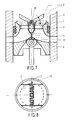
- Figures 7 and 8 illustrate views in section of the device constituted by a valve of the type "Butterfly", which offers a smaller footprint than the traditionally known valve known as the tail ”.
- the device according to the present invention has to reduce this type of two-stroke engine, the device for sending a gas intake by the valve (2) through the piston (1), driving before them in a completely simultaneous way, the gases burns which are discharged through the valve exhaust (5).
- This operation being between the AOE (Advance Opening to Exhaust) phase, illustrated Figure 11, and the RFA phase (Closure Delay at Admission), illustrated in figure 9, during a position about 130 degrees after Top Dead Center (TDC), and more than 40 degrees after the bottom dead center (PMB).
- Figures 13 and 14 show a mode sealing possible by non-return valve controlled by the position of the piston, in case the skirt of the piston because of its low height could discover the orifices of the cylinder through which the gases circulate, when the piston is in the high position in the cylinder.
- a valve is illustrated with a stepped valve to decompress the gases contained between the cylinder and the piston, when the exhaust is will do by the interior of said on-board valve and by inside said piston.
- the piston consists of a double shirt ensuring the intake gas flow between ports practiced at the bottom of the skirt and the waterproof chamber serving seat to said valve.
- the invention applies in particular to direct injection engines, in which the air which feeds the engine is introduced into the cylinder at from a turbo-compressor, independently compared to fuel.
- Figure 15 illustrates a check valve at leaf located in the exhaust gas line, so avoid reflux from the evacuation of others cylinders opening into the exhaust manifold, in the event that the gases are evacuated by inside the piston.
- this type of valve forming the piston head can be used for any pump or motor carrying a fluid to fill or empty a cylinder.
Applications Claiming Priority (2)
| Application Number | Priority Date | Filing Date | Title |
|---|---|---|---|
| FR0104344 | 2001-03-30 | ||
| FR0104344A FR2822892B1 (fr) | 2001-03-30 | 2001-03-30 | Moteur a explosion a piston a deplacement lineaire dont la tete de piston est equipee d'au moins une soupape permettant de faire circuler les gaz par l'interieur du piston |
Publications (1)
| Publication Number | Publication Date |
|---|---|
| EP1245800A1 true EP1245800A1 (de) | 2002-10-02 |
Family
ID=8861754
Family Applications (1)
| Application Number | Title | Priority Date | Filing Date |
|---|---|---|---|
| EP02290803A Withdrawn EP1245800A1 (de) | 2001-03-30 | 2002-03-29 | Vorrichtung, welche in einem Verbrennungsmotor den gleichzeitigen Einlass und Auslass von einströmendem und verbranntem Gas ermöglicht |
Country Status (2)
| Country | Link |
|---|---|
| EP (1) | EP1245800A1 (de) |
| FR (1) | FR2822892B1 (de) |
Cited By (6)
| Publication number | Priority date | Publication date | Assignee | Title |
|---|---|---|---|---|
| DE102004013461A1 (de) * | 2004-03-18 | 2005-10-13 | Rolka, Gerard, Dipl.-Ing. | Verbrennungs-4-Takt-Kolbenmotor mit axialstromigem zyklischem Gaswechsel im Zylinder und zentral liegender geteilter Brennkammer |
| CN102678263A (zh) * | 2012-06-05 | 2012-09-19 | 江苏田娘农业科技有限公司 | 活塞供气气缸组件 |
| EP2711530A1 (de) * | 2012-09-21 | 2014-03-26 | Wärtsilä Schweiz AG | Kolben, sowie Zylinderanordnung für eine längsgespülte Hubkolbenbrennkraftmaschine |
| US20140261347A1 (en) * | 2013-03-15 | 2014-09-18 | Mcalister Technologies, Llc | Internal combustion engine and associated systems and methods |
| CN107120155A (zh) * | 2017-06-02 | 2017-09-01 | 中国北方发动机研究所(天津) | 带有活塞内置气门和顶置可变气门的发动机及其控制方法 |
| CN107355308A (zh) * | 2017-06-02 | 2017-11-17 | 中国北方发动机研究所(天津) | 一种内置气门的活塞结构 |
Citations (3)
| Publication number | Priority date | Publication date | Assignee | Title |
|---|---|---|---|---|
| US2781031A (en) * | 1953-06-01 | 1957-02-12 | Barberi Giuseppe | Valve arrangement for internal combustion engines |
| US5603291A (en) * | 1995-11-14 | 1997-02-18 | Al-Kaheli; Ismail A. | Internal combustion engine with valve built into piston head |
| DE19705178A1 (de) * | 1997-02-11 | 1998-01-29 | Andreas Mozzi | Hubkolbenmotor mit Einlaßkanal im Kolben |
-
2001
- 2001-03-30 FR FR0104344A patent/FR2822892B1/fr not_active Expired - Fee Related
-
2002
- 2002-03-29 EP EP02290803A patent/EP1245800A1/de not_active Withdrawn
Patent Citations (3)
| Publication number | Priority date | Publication date | Assignee | Title |
|---|---|---|---|---|
| US2781031A (en) * | 1953-06-01 | 1957-02-12 | Barberi Giuseppe | Valve arrangement for internal combustion engines |
| US5603291A (en) * | 1995-11-14 | 1997-02-18 | Al-Kaheli; Ismail A. | Internal combustion engine with valve built into piston head |
| DE19705178A1 (de) * | 1997-02-11 | 1998-01-29 | Andreas Mozzi | Hubkolbenmotor mit Einlaßkanal im Kolben |
Cited By (10)
| Publication number | Priority date | Publication date | Assignee | Title |
|---|---|---|---|---|
| DE102004013461A1 (de) * | 2004-03-18 | 2005-10-13 | Rolka, Gerard, Dipl.-Ing. | Verbrennungs-4-Takt-Kolbenmotor mit axialstromigem zyklischem Gaswechsel im Zylinder und zentral liegender geteilter Brennkammer |
| DE102004013461B4 (de) * | 2004-03-18 | 2007-03-01 | Rolka, Gerard, Dipl.-Ing. | Verbrennungs-4-Takt-Kolbenmotor mit axialstromigem zyklischem Gaswechsel im Zylinder und zentral liegender geteilter Brennkammer |
| CN102678263A (zh) * | 2012-06-05 | 2012-09-19 | 江苏田娘农业科技有限公司 | 活塞供气气缸组件 |
| EP2711530A1 (de) * | 2012-09-21 | 2014-03-26 | Wärtsilä Schweiz AG | Kolben, sowie Zylinderanordnung für eine längsgespülte Hubkolbenbrennkraftmaschine |
| US20140261347A1 (en) * | 2013-03-15 | 2014-09-18 | Mcalister Technologies, Llc | Internal combustion engine and associated systems and methods |
| US9091204B2 (en) * | 2013-03-15 | 2015-07-28 | Mcalister Technologies, Llc | Internal combustion engine having piston with piston valve and associated method |
| CN107120155A (zh) * | 2017-06-02 | 2017-09-01 | 中国北方发动机研究所(天津) | 带有活塞内置气门和顶置可变气门的发动机及其控制方法 |
| CN107355308A (zh) * | 2017-06-02 | 2017-11-17 | 中国北方发动机研究所(天津) | 一种内置气门的活塞结构 |
| CN107355308B (zh) * | 2017-06-02 | 2019-03-22 | 中国北方发动机研究所(天津) | 一种内置气门的活塞结构 |
| CN107120155B (zh) * | 2017-06-02 | 2019-03-22 | 中国北方发动机研究所(天津) | 带有活塞内置气门和顶置可变气门的发动机及其控制方法 |
Also Published As
| Publication number | Publication date |
|---|---|
| FR2822892A1 (fr) | 2002-10-04 |
| FR2822892B1 (fr) | 2003-06-27 |
Similar Documents
| Publication | Publication Date | Title |
|---|---|---|
| WO1979000757A1 (fr) | Perfectionnements a des moteurs deux temps ameliorant la combustion et permettant une reduction de la pollution | |
| EP1245800A1 (de) | Vorrichtung, welche in einem Verbrennungsmotor den gleichzeitigen Einlass und Auslass von einströmendem und verbranntem Gas ermöglicht | |
| EP0786045B1 (de) | Zweitaktmotor mit verbesserter einspritzanordnung und verfahren zu deren einspritzung | |
| EP0691472B1 (de) | Brennkraftmaschine mit Druckbehälter für spezifische Anwendungen | |
| FR2736091A1 (fr) | Moteur a deux temps comportant un orifice supplementaire | |
| CA2492844C (fr) | Actionneur hydraulique de soupapes pour moteur a pistons | |
| EP0250960B1 (de) | Brennkraftmaschine | |
| EP0358655B1 (de) | Verfahren und einrichtung für eine zweitakt-brennkraftmaschine mit nachladung | |
| FR2763644A1 (fr) | Moteur a combustion interne a deux temps | |
| EP2166198B1 (de) | Verfahren zur Regelung der Ein- und Auslassventilsteuerung einer Brennkraftmaschine, bei welcher zumindest ein Zylinder abgeschaltet werden kann und Motor, der nach diesem Verfahren betrieben wird | |
| FR2547867A1 (fr) | Culasse perfectionnee, notamment pour moteurs a explosion, et son application a un compresseur de fluides | |
| FR2739659A1 (fr) | Moteur a 3 temps egaux, dont le mouvement rectiligne des bielles permet d'obturer le bas des cylindres et d'utiliser le volume cree en chambre d'admission | |
| FR2734317A1 (fr) | Moteur a balayage integral des gaz | |
| EP2674601A1 (de) | Verfahren zur Spülung der Restabgase durch doppelten Ventilhub für einen Zweitaktmotor, insbesondere vom Dieseltyp | |
| FR2566459A1 (fr) | Procede d'amelioration du fonctionnement d'un moteur a combustion interne et moteur a combustion interne a fonctionnement ameliore et structure simplifiee | |
| FR2795133A1 (fr) | Procede de commande d'un moteur a combustion en vue de l'obtention d'un effet de frein moteur | |
| EP0015792A1 (de) | Verfahren zum Laden eines Zwei-Takt-Verbrennungsmotors und Zwei-Takt-Verbrennungsmotoren mit ausbalancierendem Kolben und mit Kraftstoff/Luftgemisch-Einspritzung | |
| FR2554166A2 (fr) | Moteur diesel a refroidissement par eau utilisable comme moteur hors-bord | |
| FR2739412A1 (fr) | Distribution par piston pivotant pour moteur deux temps | |
| WO1995031634A1 (fr) | Systeme de clapets d'air combines avec chambre de distribution | |
| FR2810077A1 (fr) | Perfectionnements aux moteurs a deux temps | |
| FR2531139A1 (fr) | Dispositif de controle d'un circuit de gaz d'une chambre de combustion | |
| FR3085440A1 (fr) | Procede de controle d'un moteur a combustion interne avec double admission | |
| FR3109172A1 (fr) | Moteur boxer en X | |
| FR3094410A1 (fr) | Moteur a combustion interne comprenant au moins une vanne situee en amont de la soupape d’admission |
Legal Events
| Date | Code | Title | Description |
|---|---|---|---|
| PUAI | Public reference made under article 153(3) epc to a published international application that has entered the european phase |
Free format text: ORIGINAL CODE: 0009012 |
|
| AK | Designated contracting states |
Kind code of ref document: A1 Designated state(s): AT BE CH CY DE DK ES FI FR GB GR IE IT LI LU MC NL PT SE TR |
|
| AX | Request for extension of the european patent |
Free format text: AL;LT;LV;MK;RO;SI |
|
| 17P | Request for examination filed |
Effective date: 20030228 |
|
| AKX | Designation fees paid |
Designated state(s): DE ES FR GB IT |
|
| STAA | Information on the status of an ep patent application or granted ep patent |
Free format text: STATUS: THE APPLICATION HAS BEEN WITHDRAWN |
|
| 18W | Application withdrawn |
Effective date: 20040308 |