EP1245483A2 - Bicycle control device - Google Patents
Bicycle control device Download PDFInfo
- Publication number
- EP1245483A2 EP1245483A2 EP02005637A EP02005637A EP1245483A2 EP 1245483 A2 EP1245483 A2 EP 1245483A2 EP 02005637 A EP02005637 A EP 02005637A EP 02005637 A EP02005637 A EP 02005637A EP 1245483 A2 EP1245483 A2 EP 1245483A2
- Authority
- EP
- European Patent Office
- Prior art keywords
- control mechanism
- brake
- lever
- pulling
- release
- Prior art date
- Legal status (The legal status is an assumption and is not a legal conclusion. Google has not performed a legal analysis and makes no representation as to the accuracy of the status listed.)
- Granted
Links
Images





Classifications
-
- B—PERFORMING OPERATIONS; TRANSPORTING
- B62—LAND VEHICLES FOR TRAVELLING OTHERWISE THAN ON RAILS
- B62K—CYCLES; CYCLE FRAMES; CYCLE STEERING DEVICES; RIDER-OPERATED TERMINAL CONTROLS SPECIALLY ADAPTED FOR CYCLES; CYCLE AXLE SUSPENSIONS; CYCLE SIDECARS, FORECARS, OR THE LIKE
- B62K23/00—Rider-operated controls specially adapted for cycles, i.e. means for initiating control operations, e.g. levers, grips
- B62K23/02—Rider-operated controls specially adapted for cycles, i.e. means for initiating control operations, e.g. levers, grips hand actuated
- B62K23/04—Twist grips
-
- B—PERFORMING OPERATIONS; TRANSPORTING
- B62—LAND VEHICLES FOR TRAVELLING OTHERWISE THAN ON RAILS
- B62L—BRAKES SPECIALLY ADAPTED FOR CYCLES
- B62L3/00—Brake-actuating mechanisms; Arrangements thereof
- B62L3/02—Brake-actuating mechanisms; Arrangements thereof for control by a hand lever
- B62L3/023—Brake-actuating mechanisms; Arrangements thereof for control by a hand lever acting on fluid pressure systems
-
- B—PERFORMING OPERATIONS; TRANSPORTING
- B62—LAND VEHICLES FOR TRAVELLING OTHERWISE THAN ON RAILS
- B62M—RIDER PROPULSION OF WHEELED VEHICLES OR SLEDGES; POWERED PROPULSION OF SLEDGES OR SINGLE-TRACK CYCLES; TRANSMISSIONS SPECIALLY ADAPTED FOR SUCH VEHICLES
- B62M25/00—Actuators for gearing speed-change mechanisms specially adapted for cycles
- B62M25/02—Actuators for gearing speed-change mechanisms specially adapted for cycles with mechanical transmitting systems, e.g. cables, levers
- B62M25/04—Actuators for gearing speed-change mechanisms specially adapted for cycles with mechanical transmitting systems, e.g. cables, levers hand actuated
-
- Y—GENERAL TAGGING OF NEW TECHNOLOGICAL DEVELOPMENTS; GENERAL TAGGING OF CROSS-SECTIONAL TECHNOLOGIES SPANNING OVER SEVERAL SECTIONS OF THE IPC; TECHNICAL SUBJECTS COVERED BY FORMER USPC CROSS-REFERENCE ART COLLECTIONS [XRACs] AND DIGESTS
- Y10—TECHNICAL SUBJECTS COVERED BY FORMER USPC
- Y10T—TECHNICAL SUBJECTS COVERED BY FORMER US CLASSIFICATION
- Y10T74/00—Machine element or mechanism
- Y10T74/20—Control lever and linkage systems
- Y10T74/20207—Multiple controlling elements for single controlled element
- Y10T74/20256—Steering and controls assemblies
- Y10T74/20268—Reciprocating control elements
- Y10T74/2028—Handle bar type
- Y10T74/20287—Flexible control element
-
- Y—GENERAL TAGGING OF NEW TECHNOLOGICAL DEVELOPMENTS; GENERAL TAGGING OF CROSS-SECTIONAL TECHNOLOGIES SPANNING OVER SEVERAL SECTIONS OF THE IPC; TECHNICAL SUBJECTS COVERED BY FORMER USPC CROSS-REFERENCE ART COLLECTIONS [XRACs] AND DIGESTS
- Y10—TECHNICAL SUBJECTS COVERED BY FORMER USPC
- Y10T—TECHNICAL SUBJECTS COVERED BY FORMER US CLASSIFICATION
- Y10T74/00—Machine element or mechanism
- Y10T74/20—Control lever and linkage systems
- Y10T74/20396—Hand operated
- Y10T74/20402—Flexible transmitter [e.g., Bowden cable]
- Y10T74/2042—Flexible transmitter [e.g., Bowden cable] and hand operator
-
- Y—GENERAL TAGGING OF NEW TECHNOLOGICAL DEVELOPMENTS; GENERAL TAGGING OF CROSS-SECTIONAL TECHNOLOGIES SPANNING OVER SEVERAL SECTIONS OF THE IPC; TECHNICAL SUBJECTS COVERED BY FORMER USPC CROSS-REFERENCE ART COLLECTIONS [XRACs] AND DIGESTS
- Y10—TECHNICAL SUBJECTS COVERED BY FORMER USPC
- Y10T—TECHNICAL SUBJECTS COVERED BY FORMER US CLASSIFICATION
- Y10T74/00—Machine element or mechanism
- Y10T74/20—Control lever and linkage systems
- Y10T74/20396—Hand operated
- Y10T74/20402—Flexible transmitter [e.g., Bowden cable]
- Y10T74/2042—Flexible transmitter [e.g., Bowden cable] and hand operator
- Y10T74/20438—Single rotatable lever [e.g., for bicycle brake or derailleur]
Definitions
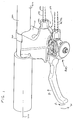
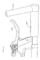
- the present invention relates generally to a bicycle control device mountable on the handlebar of a bicycle for operating cable actuated bicycle components. More particularly, the invention relates to a bicycle control device having a control lever that operates both the brake mechanism and the gear shifting mechanism.
- a bicycle control device having a control lever that is operable in a first direction to operate the brake control mechanism, a second direction to operate the shift control mechanism in the winding direction and a third direction to operate the shift control mechanism in the release direction.
- the first direction is the direction of movement of the lever toward the handlebar.
- the second direction is the direction of movement of the control lever downward and the third direction is the direction of movement of the control lever upward.
- the second and third directions are perpendicular to the first direction.
- the first direction, B is the direction of movement of the control lever 150 from a neutral position toward the handlebar 200 of the bicycle
- the second direction, W is the direction of movement of the control lever 150 from a neutral position downward
- the third direction, R is the direction of movement of the control lever 150 from a neutral position upward.
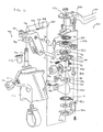
- the winding member 370 is preferably biased in the release direction, R, by second spring, S2.
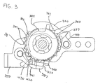
- a first latch plate 380 and a second latch plate 390 are fixedly coupled to winding member 370 such that the winding member 370, the first latch plate 380 and the second latch plate 390 rotate about the pivot shaft 310 simultaneously, as a unitary body.
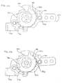
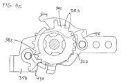
- the positioning pawl 430 is biased toward the positioning latch 382, the positioning pawl 430 engages a tooth of the positioning latch 382 adjacent the previously engaged tooth.
- the positioning pawl 430 produces an audible click when the positioning pawl 430 engages the positioning latch 382.
- the bicycle rider can feel the snap of the positioning pawl 430 engaging the positioning latch 382.
- the audible click and the snapping motion alerts the rider that the positioning pawl 430 has advance by one tooth completing one step of a multi-step shift mechanism.
- the operating plate 320 Upon completion of the one step shift, the operating plate 320 returns to the neutral position, as shown in Figure 4e.
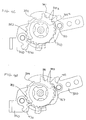
- Figures 5a and 6a illustrate the shift control mechanism 300 in a neutral position.
- the control lever 150 is operated in the release direction R, causing the operating plate 320 to rotate in the release direction.
- the operating abutment 322 pushes the releasing abutment 341, causing the releasing plate 340 to rotate.
- the release abutment 341 contacts the positioning pawl 430 and disengages the positioning pawl 430 from the positioning latch 382.
- the drawings depict a shift control mechanism for a nine step shift operation.
- the present invention is not limited to a nine step shift operation and can be configured to vary the number of steps available.
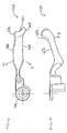
- Figure 11 discloses another preferred embodiment of the release lever 650 having a knob shape.
- the release lever 650 is preferably fastened to the releasing plate 340 using fasteners 651.
- the release lever 650 is preferably separable form the releasing plate and can be replaced without replacing the entire shift control mechanism.
- an extension 652 may be provided on the releasing plate 340 to position the release lever 650 spaced apart from the shift control mechanism, and thus allow room for the release lever 650 to operate smoothly.
Landscapes
- Engineering & Computer Science (AREA)
- Mechanical Engineering (AREA)
- Chemical & Material Sciences (AREA)
- Combustion & Propulsion (AREA)
- Transportation (AREA)
- Physics & Mathematics (AREA)
- Fluid Mechanics (AREA)
- Steering Devices For Bicycles And Motorcycles (AREA)
- Mechanical Control Devices (AREA)
Abstract
Description
Claims (51)
- A bicycle control device (100), comprising:wherein the control lever (150) is operable in a brake operating plane to operate the brake control mechanism (102); anda brake control mechanism (102);a shift control mechanism (300) having a pulling direction and a release direction;a control lever (150) operatively connected to the brake control mechanism (102) andthe shift control mechanism (300);
wherein the control lever (150) is operable in a shifting plane to operate the shift control mechanism (300) in the pulling direction and in the release direction. - The bicycle control device (100) of claim 1 wherein the pulling direction is the direction of movement of the control lever (150) downward, and the release direction is the direction of movement of the control lever (150) upward.
- The bicycle control device (100) of claim 1 or 2 wherein the brake operating plane is substantially perpendicular to the shifting plane.
- The bicycle control device (100) of any of the preceding claims wherein, in the shifting plane, the control lever (150) is pivotable between an upshift position, a neutral position and a downshift position, wherein the upshift position is on a first side of the neutral position and the downshift position is on a second side of the neutral position opposite the first side.
- The bicycle control device (100) of any of the preceding claims wherein the brake control mechanism (102) comprises:wherein the operation of the control lever (150) in the brake operating plane pivots the brake lever base (130) on the bracket (110) and actuates the cable hook (160).a bracket (110);a brake lever base (130) pivotably connected to the bracket (110);a cable hook (160) connected to the brake lever base (130), the cable hook (160) configured to receive a brake cable (170); and
- The bicycle control device (100) of any of the preceding claims wherein the shift control mechanism (300) comprises:a support shaft;a cable pulling member (470) rotatable in the pulling direction and in the release direction about the support shaft, the cable pulling member (470) configured to receive a gear-shifting cable and pull the cable when the cable pulling member (470) is rotated in the pulling direction and release the gear-shifting cable (140) when the cable pulling member (470) is rotated in the release direction;a winding mechanism (104) operatively connected to the cable pulling member (470); anda release and hold mechanism operatively connected to the cable pulling member (470).
- The bicycle control device (100) of claim 6 wherein the winding mechanism (104) comprises a winding latch (381) and a winding pawl (410) configured to cooperate with the winding latch (381).
- The bicycle control device (100) of claim 6 or 7 wherein the release and hold mechanism comprises:a first latching plate (380) having a first latching segment formed at an outer circumferential edge of the first latching plate (380);a second latching plate (390) having a second latching segment formed at an outer circumferential edge of the second latching plate (390);a positioning pawl (430) configured to engage with the first latching segment of the first latching plate (380);an interrupting pawl (420) configured to engage with the second latching segment of the second latching plate (390);the interrupting pawl (420) and positioning pawl (430) alternately engaging the corresponding second latching segment and first latching segment when the pulling member (470) operates in a release direction.
- The bicycle control device (100) of claims 6 to 8 wherein the pulling member (470) is biased in the release direction.
- The bicycle control device (100) of claims 6 to 9 wherein the positioning pawl (430) is biased toward the first latching segment formed on the first latching plate (380).
- The bicycle control device (100) of claims 6 to 10 wherein the brake control mechanism (102) comprises:wherein the operation of the control lever in the brake operating plane pivots the brake lever base on the bracket and actuates the cable hook; anda bracket (110);a brake lever base (130) pivotably connected to the bracket (110);a cable hook (160) connected to the brake lever base, the cable hook configured to receive a brake cable;
wherein the support shaft is fixedly attached to the brake lever base. - A bicycle control device (100), comprising:wherein the control lever (150) is operable in a first direction to operate the brake control mechanism (102), a second direction to operate the shift control mechanism (300) in the pulling direction and a third direction to operate the shift control mechanism (300) in the release direction.a brake control mechanism (102);a shift control mechanism (300) having a pulling direction and a release direction;a control lever (150) operatively connected to the brake control mechanism (102) andthe shift control mechanism (300); and
- The bicycle control device (100) of claim 12 wherein the second and third directions lie along the same line.
- The bicycle control device (100) of claim 12 or 13 wherein the first direction is substantially perpendicular to the second and third directions.
- A bicycle control device (100) attachable to the bicycle handlebar (200), the bicycle control device (100) comprising:wherein the control lever (150) is pivotable about a first axis to operate the brake control mechanism (102); anda brake control mechanism (102);a shift control mechanism (300) having a pulling direction and a release direction;a control lever (150) operatively connected to the brake control mechanism (102) andthe shift control mechanism (300);
wherein the control lever (150) is pivotable about a second axis to operate the shift control mechanism (300) in the pulling direction and in the release direction. - The bicycle control device (100) of claim 15 wherein the first axis is substantially perpendicular to the second axis.
- The bicycle control device (100) of claim 15 or 16 wherein the handlebar (200) comprises a flat-bar type handlebar.
- A bicycle control device (100), comprising:a brake control mechanism (102) having a bracket (110), a brake lever base (130) pivotably connected to the bracket (110), and a cable hook (160) connected to the brake lever base (130), the cable hook (160) configured to receive a brake cable (170);a shift control mechanism (300) having:a support shaft fixedly connected to the brake lever base (130) of the brake control mechanism (102);a pulling member (470) rotatable in the pulling direction and in the release direction about the support shaft, the pulling member (470) biased in the release direction and configured to receive a gear-shifting cable (142), wherein the gear-shifting cable (142) is pulled when the pulling member (470) is rotated in the pulling direction and released when the pulling member (470) is rotated in the release direction;a winding mechanism (104) comprising a winding latch (381) and a winding pawl (410) biased toward the winding latch (381) and configured to cooperate with the winding latch (381) to rotate the pulling member (470) in a pulling direction; anda release and hold mechanism comprising a first latching plate (380) having a first latching segment, a second latching plate (390) having a second latching segment, a positioning pawl (430) biased toward the first latching segment and configured to engage with the first latching segment, an interrupting pawl (420) configured to engage with the second latching segment, wherein the interrupting pawl (420) and positioning pawl (430) alternately engage the corresponding second latching segment and first latching segment when the pulling member (470) operates in the release direction; anda control lever (150) operatively connected to the brake control mechanism (102) and the shift control mechanism (300) wherein the control lever (150) is operable in a first direction to operate the brake control mechanism (102), a second direction to operate the shift control mechanism (300) in the pulling direction and a third direction to operate the shift control mechanism (300) in the release direction.
- The bicycle control device (100) of claim 18, further comprising:a fixed plate (350) fixedly connected to a mounting member (133) of the brake lever base (130);a releasing plate (340) biased toward the fixed plate (350) on a first side of the fixed plate (350);a winding plate (330) biased toward the fixed plate (350) on a second side of the fixed plate (350), opposite the first side;an operating plate (320) operatively connected to the releasing plate (340) and the winding plate (330) wherein during a release operation, the operating plate (320) operates the release plate (340) in the release direction and wherein during a winding operation, the operating plate (320) operates the winding plate (330) in the pulling direction.
- The bicycle control device (100) of claim 18 or 19 further comprising a supplemental release lever extending from the releasing plate (340).
- A shift control mechanism (300), comprising:a support shaft;a pulling member (470) rotatable in a pulling direction and in a release direction about the support shaft, the pulling member (470) biased in the release direction and configured to receive a gear-shifting cable (142), wherein the gear-shifting cable (142) is pulled when the pulling member (470) is rotated in the pulling direction and released when the pulling member is rotated in the release direction;a winding mechanism (104) comprising a winding latch (381) and a winding pawl biased toward the winding latch (381) and configured to cooperate with the winding latch (381) to rotate the pulling member (470) in a pulling direction;a release and hold mechanism comprising a first latching plate (380) having a first latching segment, a second latching plate (390) having a second latching segment, a positioning pawl (430) biased toward the first latching segment and configured to engage with the first latching segment, an interrupting pawl (420) configured to engage with the second latching segment, wherein the interrupting pawl (420) and positioning pawl (430) alternately engage the corresponding second latching segment and first latching segment when the pulling member (470) operates in the release direction; anda control lever (150) operable in a first direction to operate the shift control mechanism (300) in the pulling direction and a second direction to operate the shift control mechanism (300) in the release direction.
- The shift control mechanism (300) of claim 21, further comprising:a fixed plate (350) fixedly connected to the control lever (150);a releasing plate biased toward the fixed plate (350) from a first direction;a winding plate (330) biased toward the fixed plate (350) from a second direction, opposite the first direction;an operating plate (320) operatively connected to the releasing plate (340) and the winding plate (330) wherein during a release operation, the operating plate (320) operates the release plate (340) in the release direction and wherein during a winding operation, the operating plate (320) operates the winding plate (330) in the pulling direction.
- A method of operating a shift control mechanism (300) and a brake control mechanism (102), comprising the steps of:providing a shift control mechanism (300) operative in a pulling direction and a release direction, a brake control mechanism (102) and a control lever (150);actuating the control lever (150) in a first direction to operate the brake control mechanism (102);actuating the control lever (150) in a second direction to operate the shift control mechanism (300) in the pulling direction; andactuating the control lever (150) in a third direction to operate the shift control mechanism (300) in the release direction.
- The operating method of claim 23 wherein the second and third directions lie along the same line.
- The operating method of claim 23 or 24 wherein the first direction is perpendicular to the second and third directions.
- A method of operating a shift control mechanism (300) and a brake control mechanism (102) attached to a handlebar using a rider's fingers:providing a shift control mechanism (300) operative in a pulling direction and a release direction, a brake control mechanism (102) having a brake lever; andactuating the shift control mechanism (300) in the pulling direction and the release direction while maintaining the rider's fingers on the brake lever and the rider's thumb on the handlebar.
- The bicycle control device (100) of any of the preceding claims 1 to 20 further comprising a hydraulic brake bracket (602) operatively connected to the control lever (150).
- The bicycle control device (100) of claim 27 wherein the brake control mechanism (102) comprises:a fluid reservoir (608);an outlet (610) spaced apart from the fluid reservoir (608); anda piston (606) operatively connected to the control lever (150), wherein the movement of the piston (606) controls fluid communication between the reservoir (608) and the outlet (610).
- A bicycle control device (100), comprising:wherein the control lever (150) is operable in a brake operating plane to operate the brake control mechanism (102); anda hydraulic brake control mechanism;a shift control mechanism (300) having a pulling direction and a release direction;a control lever (150) operatively connected to the brake control mechanism (102) and the shift control mechanism (300);
wherein the control lever (150) is operable in a shifting plane to operate the shift control mechanism (300) in the pulling direction and in the release direction. - A bicycle control device (100), comprising:a brake control mechanism (102) having a bracket (110), a brake lever base (130) pivotably connected to the bracket, a fluid reservoir (608), an outlet (610) spaced apart from the fluid reservoir (608) and a piston (606) operatively connected to the control lever (150), wherein the movement of the piston (606) controls fluid communication between the reservoir (608) and the outlet (610);a shift control mechanism (300) having:a support shaft fixedly connected to the brake lever base (130) of the brake control mechanism (102);a pulling member (470) rotatable in the pulling direction and in the release direction about the support shaft, the pulling member (470) biased in the release direction and configured to receive a gear-shifting cable (140), wherein the gear-shifting cable (140) is wound on the pulling member (470) when the pulling member (470) is rotated in the pulling direction and released when the pulling member (470) is rotated in the release direction;a winding mechanism (104) comprising a winding latch (381) and a winding pawl (410) biased toward the winding latch (381) and configured to cooperate with the winding latch (381) to rotate the pulling member (470) in a pulling direction; anda release and hold mechanism comprising a first latching plate (380) having a first latching segment, a second latching plate (390) having a second latching segment, a positioning pawl (430) biased toward the first latching segment and configured to engage with the first latching segment, an interrupting pawl (420) configured to engage with the second latching segment, wherein the interrupting pawl (420) and positioning pawl (430) alternately engage the corresponding second latching segment and first latching segment when the pulling member (470) operates in the release direction; anda control lever (150) operatively connected to the brake control mechanism (102) and the shift control mechanism (300) wherein the control lever (150) is operable in a first direction (300) to operate the brake control mechanism (102), a second direction to operate the shift control mechanism (300) in the pulling direction and a third direction to operate the shift control mechanism (300) in the release direction.
- The bicycle control device (100) of claim 6 wherein the gear-shifting cable (140) is wound on the cable pulling member (470) when the cable pulling member (470) is rotated in the pulling direction.
- The bicycle control device (100) of claim 18 wherein the gear-shifting cable (140) is wound on the cable pulling member (470) when the cable pulling member (470) is rotated in the pulling direction.
- The bicycle control device (100) of claim 21 wherein the gear-shifting cable (140) is wound on the cable pulling member (470) when the cable pulling member (470) is rotated in the pulling direction.
- A bicycle control device (100), comprising:a brake control mechanism (102);a shift control mechanism (300) having a pulling direction and a release direction;a control lever (150) operatively connected to the brake control mechanism (102) and the shift control mechanism (300);wherein the control lever (150) is operable in a brake operating plane to operate the brake control mechanism (102);a gear-shifting cable (140) received by the shift control mechanism (300) at a substantially parallel relationship to the control lever (150), wherein the cable (140) is operatively connected to the control lever (150) and the shift control mechanism (300), andwherein the control lever (150) operates the shift control mechanism (300) in the pulling direction and in the release direction.
- The bicycle control device (100) of claim 19 further comprising a detent assembly (620) engageable with a slot (622) in the operating plate (320), when the operating plate (320) is in a neutral position.
- The bicycle control device (100) of claim 35 wherein the detent assembly (620) further comprises a spring (626) and a ball (624), wherein the spring (626) biases the ball (624) toward the slot (622) in the operating plate (320).
- The bicycle control device (100) of claim 35 or 36 wherein the ball (624) and spring (626) are housed in a mounting member (133) of the brake lever base (130).
- The bicycle control device (100) of claim 22 further comprising a detent assembly (620) engageable with a slot in the operating plate (320), when the operating plate (320) is in a neutral position.
- The bicycle control device (100) of claim 38 wherein the detent assembly further comprises a spring (626) and a ball (624), wherein the spring (626) biases the ball (624) toward the slot (622) in the operating plate (320).
- The bicycle control device (100) of claim 38 or 39 wherein the ball (624) and spring (626) are housed in a mounting member of the brake lever base.
- A bicycle control device (100), comprising:wherein the control lever (150) is operable in a brake operating plane to operate the brake control mechanism (102);a brake control mechanism (102);a shift control mechanism (300) having an operating plate (320), the operating plate (320) operable in a pulling direction and a release direction;a control lever (150) operatively connected to the brake control mechanism (102) and the shift control mechanism (300);
wherein the control lever (150) is operable in a shifting plane to operate the shift control mechanism (300) in the pulling direction and in the release direction; and
wherein in a neutral position, the operating plate (320) is held stationary using a detent assembly (620). - A bicycle control device (100), comprising:wherein the control lever (150) is operable in a brake operating plane to operate the brake control mechanism (102); anda brake control mechanism (102);a shift control mechanism (300) having a pulling direction and a release direction;a bearing assembly operatively connected to the shift control mechanism (300) to minimize friction and smoothly operate the shift control mechanism (300) in the pulling and release directions;a control lever (150) operatively connected to the brake control mechanism (102) and the shift control mechanism (300);
wherein the control lever (150) is operable in a shifting plane to operate the shift control mechanism (300) in the pulling direction and in the release direction. - The bicycle control device (100) of claim 41 wherein the control lever is connected to the operating plate via fasteners and is removable therefrom.
- The bicycle control device (100) of claim 41 or 43 wherein the control lever (150) comprises a narrow portion.
- A bicycle control device (100), comprising:wherein the control lever (150) is operable in a brake operating plane to operate the brake control mechanism (102);a brake control mechanism (102);a shift control mechanism (300) having a pulling direction and a release direction;a control lever (150) operatively connected to the brake control mechanism (102) and the shift control mechanism (300);
wherein the control lever (150) is operable in a shifting plane to operate the shift control mechanism (300) in the pulling direction and in the release direction; and
a supplemental release lever operatively connected to the shift control mechanism (300) and configured to operate the shift control mechanism (300) in the release direction. - The bicycle control device (100) of claim 45 wherein the supplemental release lever is detachable from the shift control mechanism (300).
- A control lever (150) operable in a pulling direction, releasing direction and a braking direction, the control lever (150) comprising:a releasing surface (666);a pulling surface (664) opposite the releasing surface (666);a braking surface (672) adjacent the pulling surface and the releasing surface (666);the pulling surface (664) defining a first projection (668) at a distal end thereof;the releasing surface (666) defining a second projection (670) at a distal end thereof; andthe braking surface (672) defining a third projection (674) at a distal end thereof.
- The control lever (150) of claim 47 wherein the first, second and third projections (668, 670, 674) are configured to facilitate the operation of the control lever (150).
- The control lever (150) of claim 47 or 48 further comprising a proximal end (660) opposite the distal end (662), the proximal end (660) defining a narrow portion (640).
- The control lever (150) of claims 47 to 49 wherein the third projection (674) is larger than the first projection (668).
- The control lever (150) of claims 47 to 50 wherein the first projection (668) is larger than the second projection (670).
Applications Claiming Priority (4)
| Application Number | Priority Date | Filing Date | Title |
|---|---|---|---|
| US09/823,287 US20020139218A1 (en) | 2001-03-30 | 2001-03-30 | Bicycle control device |
| US823287 | 2001-03-30 | ||
| US995060 | 2001-11-26 | ||
| US09/995,060 US6647823B2 (en) | 2001-03-30 | 2001-11-26 | Bicycle control device |
Publications (3)
| Publication Number | Publication Date |
|---|---|
| EP1245483A2 true EP1245483A2 (en) | 2002-10-02 |
| EP1245483A3 EP1245483A3 (en) | 2005-01-26 |
| EP1245483B1 EP1245483B1 (en) | 2009-10-21 |
Family
ID=27124723
Family Applications (1)
| Application Number | Title | Priority Date | Filing Date |
|---|---|---|---|
| EP02005637A Expired - Lifetime EP1245483B1 (en) | 2001-03-30 | 2002-03-12 | Bicycle control device |
Country Status (6)
| Country | Link |
|---|---|
| US (2) | US6691591B2 (en) |
| EP (1) | EP1245483B1 (en) |
| JP (1) | JP3769237B2 (en) |
| CN (1) | CN1304240C (en) |
| CZ (1) | CZ20021106A3 (en) |
| TW (1) | TW558538B (en) |
Cited By (14)
| Publication number | Priority date | Publication date | Assignee | Title |
|---|---|---|---|---|
| EP1440878A3 (en) * | 2003-01-27 | 2005-02-02 | Shimano Inc. | Apparatus for shifting a bicycle transmission |
| EP1650123A3 (en) * | 2004-10-25 | 2006-11-02 | Shimano Inc. | Shift and brake control device |
| EP1854713A2 (en) | 2006-05-10 | 2007-11-14 | Shimano Inc. | Bicycle shifting mechanism |
| EP1813525A3 (en) * | 2006-01-31 | 2008-01-23 | Shimano Inc. | Bicycle shift control device |
| EP2008924A1 (en) * | 2007-06-25 | 2008-12-31 | Shimano Inc. | Bicycle control device |
| EP1927541A3 (en) * | 2006-11-29 | 2009-02-25 | Shimano Inc. | Bicycle gear shifter |
| US7665382B2 (en) | 2006-02-07 | 2010-02-23 | Shimano Inc. | Bicycle shift control device |
| US7762157B2 (en) | 2005-10-06 | 2010-07-27 | Shimano, Inc. | Bicycle shift operating device with a multi-direction operating member |
| EP1955937A3 (en) * | 2007-02-09 | 2012-09-26 | CAMPAGNOLO S.r.l. | Control device for a derailleur of a bicycle |
| US9267536B2 (en) | 2005-06-27 | 2016-02-23 | Campagnolo S.R.L. | Control device for a bicycle derailleur |
| US9797434B2 (en) | 2005-09-14 | 2017-10-24 | Shimano, Inc. | Bicycle shift operating device with a multi-direction operating member |
| US10118664B2 (en) | 2007-03-01 | 2018-11-06 | Campagnolo S.R.L. | Control device for a bicycle and bicycle comprising such a device |
| US10202164B2 (en) | 2004-02-06 | 2019-02-12 | Campagnolo S.R.L. | Actuation device for a control cable for a bicycle gearshift |
| EP2527238B2 (en) † | 2011-05-26 | 2019-06-19 | Shimano Inc. | Shift positioning mechanism |
Families Citing this family (32)
| Publication number | Priority date | Publication date | Assignee | Title |
|---|---|---|---|---|
| ITTO20011079A1 (en) | 2001-11-16 | 2003-05-16 | Campagnolo Srl | ,, GEARBOX CONTROL DEVICE FOR A BICYCLE WITH A HANDLEBAR WITH STRAIGHT ENDS ,, |
| US6868752B2 (en) * | 2002-07-05 | 2005-03-22 | Shimano, Inc. | Assisting apparatus for changing speeds in a bicycle transmission |
| US7011590B2 (en) * | 2003-07-08 | 2006-03-14 | Shimano, Inc. | Shift assist apparatus for a bicycle transmission |
| US7228756B2 (en) * | 2003-11-25 | 2007-06-12 | Shimano Inc. | Bicycle control device |
| JP2006111086A (en) * | 2004-10-13 | 2006-04-27 | Yamaha Motor Co Ltd | Motorcycle |
| US8181553B2 (en) | 2004-10-25 | 2012-05-22 | Shimano Inc. | Position control mechanism for bicycle control device |
| JP2006224875A (en) * | 2005-02-18 | 2006-08-31 | Shimano Inc | Shift control device for bicycle |
| US7918145B1 (en) * | 2005-05-18 | 2011-04-05 | Calendrille Jr John L | Combination shift and brake lever arrangement for a bicycle |
| US7527137B1 (en) | 2005-05-18 | 2009-05-05 | Calendrille Jr John L | Combination shift and brake lever arrangement for a bicycle |
| JP5027999B2 (en) * | 2005-07-08 | 2012-09-19 | キヤノン株式会社 | Recording apparatus and control method thereof |
| US7526979B2 (en) * | 2005-07-19 | 2009-05-05 | Shimano Inc. | Bicycle shift position control mechanism |
| DE202006008605U1 (en) * | 2005-12-01 | 2006-10-26 | Shimano Inc., Sakai | Bicycle movement controlling unit, has two levers independent of each other, where one lever can be actuated from starting position to control position by exertion of pressure on one of the actuation areas of respective lever |
| JP2009523652A (en) | 2006-01-23 | 2009-06-25 | カンパニョーロ・ソシエタ・ア・レスポンサビリタ・リミタータ | Control device for bicycle derailleur |
| US20070199400A1 (en) * | 2006-02-16 | 2007-08-30 | Kennith Hall | Actuation lever system with breakaway element and simple assembly |
| EP1826111B1 (en) | 2006-02-23 | 2010-06-30 | CAMPAGNOLO S.r.l. | Bicycle brake control device |
| ITMI20072230A1 (en) | 2007-11-23 | 2009-05-24 | Campagnolo Srl | CONTROL DEVICE FOR BICYCLE WITH RECURCED HANDLEBAR |
| US8863611B2 (en) * | 2008-10-08 | 2014-10-21 | Sram, Llc | Bicycle control device |
| JP5268572B2 (en) * | 2008-11-06 | 2013-08-21 | 株式会社ミクニ | Accelerator operating device |
| US8286529B2 (en) * | 2009-01-26 | 2012-10-16 | Shimano Inc. | Bicycle control device |
| US8584550B1 (en) | 2009-05-18 | 2013-11-19 | John L. Calendrille, Jr. | Shift lever arrangement for a bicycle |
| US9651138B2 (en) | 2011-09-30 | 2017-05-16 | Mtd Products Inc. | Speed control assembly for a self-propelled walk-behind lawn mower |
| JP3181557U (en) | 2012-11-29 | 2013-02-14 | 株式会社シマノ | Bicycle control device |
| US9919760B2 (en) * | 2014-03-12 | 2018-03-20 | Shimano Inc. | Bicycle operating device |
| JP2015223985A (en) * | 2014-05-29 | 2015-12-14 | 株式会社シマノ | Operation device for bicycle |
| US9321501B1 (en) * | 2014-10-31 | 2016-04-26 | Shimano Inc. | Bicycle control device |
| US10005521B2 (en) * | 2016-11-14 | 2018-06-26 | Shimano Inc. | Bicycle component operating device |
| JP6921724B2 (en) * | 2017-11-30 | 2021-08-18 | 株式会社シマノ | Shift control device and electric shift system |
| US11021213B2 (en) | 2018-12-10 | 2021-06-01 | Shimano Inc. | Bicycle operating device |
| US10780948B2 (en) * | 2018-12-10 | 2020-09-22 | Shimano Inc. | Bicycle operating device |
| TWI730756B (en) * | 2020-05-08 | 2021-06-11 | 彥豪金屬工業股份有限公司 | Bicycle shift operating device |
| DE102021100615A1 (en) | 2021-01-14 | 2022-07-14 | Shimano (Singapore) Pte. Ltd. | operating device |
| CN115258031B (en) * | 2022-06-10 | 2023-09-05 | 佛山市博力为智能科技有限公司 | Speed-changing operating device for bicycle |
Family Cites Families (48)
| Publication number | Priority date | Publication date | Assignee | Title |
|---|---|---|---|---|
| US598762A (en) | 1898-02-08 | Variable-speed gear | ||
| US1709346A (en) | 1929-04-16 | garrard | ||
| US648059A (en) | 1899-07-08 | 1900-04-24 | Daniel T Keenan | Motor-vehicle. |
| US1185546A (en) | 1915-07-07 | 1916-05-30 | John Hampson | Variable-speed planetary gearing. |
| GB134931A (en) | 1918-11-13 | 1919-11-13 | Percy Richard Webb | Improved Control Mechanism for Regulating the Supply of Fuel and of Air to the Carburettor of an Internal Combustion Engine. |
| US1666793A (en) | 1926-09-10 | 1928-04-17 | Sanguineti Adolphus | Controlling means of variable-speed gearing for motor vehicles having handlebars |
| US2242145A (en) * | 1940-04-16 | 1941-05-13 | William G Lathrop | Combination brake and accelerator pedal |
| US2422343A (en) | 1943-06-14 | 1947-06-17 | Morris J Duer | Speed control device |
| US2336682A (en) | 1943-06-17 | 1943-12-14 | Angus R Gross | Combination lever |
| US2490783A (en) | 1947-06-25 | 1949-12-13 | Marion W Cullen | Ratio demonstrator for planetary gearing |
| FR1007339A (en) | 1949-12-19 | 1952-05-05 | Magenwirth Kg Gustav | Rotating handle, in particular operating handle for motorcycles |
| US2796773A (en) | 1952-12-17 | 1957-06-25 | Wooler John | Combination control assemblies applicable to motorcycles |
| US2745297A (en) | 1953-01-28 | 1956-05-15 | Budd W Andrus | Reversible speed changer |
| US2789648A (en) | 1955-02-24 | 1957-04-23 | Colson Corp | Power operated material handling trucks |
| US2931250A (en) | 1955-05-23 | 1960-04-05 | Ebert Heinrich | Hydrostatic transmission |
| US3029916A (en) * | 1960-05-20 | 1962-04-17 | Hermanus N Luijt | Combined brake and accelerator pedal |
| US3298174A (en) | 1965-06-11 | 1967-01-17 | Fairchild Hiller Corp | Control system for infinitely variable automatic transmission |
| US3331479A (en) * | 1965-08-18 | 1967-07-18 | Pascual Antonio Frontera | System of combined accelerator and brake pedal control for automobiles |
| US3478617A (en) | 1967-09-01 | 1969-11-18 | Tetsuo Maeda | Gearbox change lever for bicycles |
| US3534629A (en) | 1967-10-14 | 1970-10-20 | Fichtel & Sachs Ag | Control mechanism for a bicycle |
| FR1572984A (en) | 1967-11-22 | 1969-07-04 | ||
| US3554158A (en) | 1968-05-11 | 1971-01-12 | Keizo Shimano | Indicating system of operational state of the parking brake for a bicycle |
| US3567250A (en) | 1969-03-12 | 1971-03-02 | Huffman Mfg Co | Bicycle with improved brake system |
| JPS4824188B1 (en) | 1969-03-13 | 1973-07-19 | ||
| US3709338A (en) * | 1970-09-28 | 1973-01-09 | E Glen | Single pedal brake-accelerator mechanism with cruise control |
| US3808907A (en) | 1972-06-09 | 1974-05-07 | E Yamaguchi | Shift lever device for speed change gear transmission train of a bicycle |
| US3934492A (en) | 1973-12-26 | 1976-01-27 | Timbs Norman E | Variable speed drive for bicycles and the like |
| US4002350A (en) | 1975-03-17 | 1977-01-11 | Timbs Norman E | Single lever control for variable speed bicycles and the like |
| US4100820A (en) | 1976-09-13 | 1978-07-18 | Joel Evett | Shift lever and integral handbrake apparatus |
| JPS5742158Y2 (en) | 1978-10-06 | 1982-09-16 | ||
| US4548092A (en) | 1983-02-10 | 1985-10-22 | Strong Jr Samuel Z | Bicycle gear shift unit |
| US5251878A (en) | 1988-05-28 | 1993-10-12 | Zahnradfabrik Friedrichshafen Ag | Drive for lifting equipment |
| US5400675A (en) * | 1988-11-29 | 1995-03-28 | Shimano, Inc. | Bicycle control device |
| US5241878A (en) | 1988-11-29 | 1993-09-07 | Shimano, Inc. | Bicycle control device |
| JP2732116B2 (en) * | 1988-11-29 | 1998-03-25 | 株式会社シマノ | Bicycle operation device |
| JPH04331689A (en) | 1991-01-10 | 1992-11-19 | Maeda Kogyo Kk | Brake lever device for bicycle |
| IT1245445B (en) | 1991-03-11 | 1994-09-20 | Campagnolo Srl | TRANSMISSION AND BRAKE CONTROL UNIT FOR A BICYCLE |
| JP3245188B2 (en) | 1991-04-19 | 2002-01-07 | 株式会社シマノ | Speed change device for bicycle |
| IT1261550B (en) * | 1993-04-20 | 1996-05-23 | Antonio Romano | CONTROL DEVICE FOR THE CHANGE OF A BICYCLE. |
| FR2705079B1 (en) * | 1993-05-11 | 1995-08-04 | Sachs Ind Sa | CONTROL DEVICE FOR BRAKE AND CYCLE DERAILLEUR. |
| IT1285834B1 (en) | 1995-10-19 | 1998-06-24 | Campagnolo Srl | CONTROL DEVICE OF A BICYCLE DERAILLEUR, INCLUDING AN ANTAGONIST SPRING OF THE DERAILLEUR SPRING. |
| US5775168A (en) * | 1996-02-14 | 1998-07-07 | Shimano, Inc. | Combined brake and shifting device |
| JP3321045B2 (en) * | 1996-12-20 | 2002-09-03 | 株式会社シマノ | Bicycle electrical operating device |
| US5881602A (en) | 1997-03-20 | 1999-03-16 | Cirami; Salvatore | Gearshift for dual derailleur bicycle |
| ITTO980492A1 (en) | 1998-06-05 | 1999-12-05 | Campagnolo Srl | GEAR CONTROL UNIT FOR BICYCLE, FITTED WITH TRANSDUCER DEVICE, AND TRANSDUCER DEVICE USED IN THIS GROUP. |
| US6164421A (en) * | 1998-10-14 | 2000-12-26 | Shimano Inc. | Disc brake assembly |
| US6095309A (en) | 1998-11-12 | 2000-08-01 | At Design Inc. | Cycle handlebar actuator |
| JP4010762B2 (en) | 2000-11-21 | 2007-11-21 | 本田技研工業株式会社 | Bicycle handle lever |
-
2002
- 2002-03-05 TW TW091104065A patent/TW558538B/en not_active IP Right Cessation
- 2002-03-12 EP EP02005637A patent/EP1245483B1/en not_active Expired - Lifetime
- 2002-03-26 JP JP2002085603A patent/JP3769237B2/en not_active Expired - Fee Related
- 2002-03-27 CN CNB021082243A patent/CN1304240C/en not_active Expired - Fee Related
- 2002-03-28 CZ CZ20021106A patent/CZ20021106A3/en unknown
-
2003
- 2003-02-19 US US10/371,687 patent/US6691591B2/en not_active Expired - Fee Related
- 2003-09-02 US US10/654,357 patent/US7267026B2/en not_active Expired - Fee Related
Non-Patent Citations (1)
| Title |
|---|
| None |
Cited By (26)
| Publication number | Priority date | Publication date | Assignee | Title |
|---|---|---|---|---|
| EP1440878A3 (en) * | 2003-01-27 | 2005-02-02 | Shimano Inc. | Apparatus for shifting a bicycle transmission |
| US7152497B2 (en) | 2003-01-27 | 2006-12-26 | Shimano, Inc. | Method and apparatus for shifting a bicycle transmission by multiple steps |
| CN100384688C (en) * | 2003-01-27 | 2008-04-30 | 株式会社岛野 | Position release mechanism for bicycle controls |
| US10202164B2 (en) | 2004-02-06 | 2019-02-12 | Campagnolo S.R.L. | Actuation device for a control cable for a bicycle gearshift |
| EP1650123A3 (en) * | 2004-10-25 | 2006-11-02 | Shimano Inc. | Shift and brake control device |
| EP1783044A3 (en) * | 2004-10-25 | 2007-05-16 | Shimano Inc. | Shift and brake control device |
| US9802671B2 (en) | 2005-06-27 | 2017-10-31 | Campagnolo S.R.L. | Control device for a bicycle derailleur |
| US9267536B2 (en) | 2005-06-27 | 2016-02-23 | Campagnolo S.R.L. | Control device for a bicycle derailleur |
| US9797434B2 (en) | 2005-09-14 | 2017-10-24 | Shimano, Inc. | Bicycle shift operating device with a multi-direction operating member |
| US7762157B2 (en) | 2005-10-06 | 2010-07-27 | Shimano, Inc. | Bicycle shift operating device with a multi-direction operating member |
| US7665383B2 (en) | 2006-01-31 | 2010-02-23 | Shimano Inc. | Bicycle shift control device |
| EP1813525A3 (en) * | 2006-01-31 | 2008-01-23 | Shimano Inc. | Bicycle shift control device |
| US7665382B2 (en) | 2006-02-07 | 2010-02-23 | Shimano Inc. | Bicycle shift control device |
| EP1854713A3 (en) * | 2006-05-10 | 2008-03-05 | Shimano Inc. | Bicycle shifting mechanism |
| US7628095B2 (en) | 2006-05-10 | 2009-12-08 | Shimano Inc. | Bicycle shifting mechanism |
| EP1854713A2 (en) | 2006-05-10 | 2007-11-14 | Shimano Inc. | Bicycle shifting mechanism |
| EP1927541A3 (en) * | 2006-11-29 | 2009-02-25 | Shimano Inc. | Bicycle gear shifter |
| US7947914B2 (en) | 2006-11-29 | 2011-05-24 | Shimano Inc. | Bicycle shift operating device |
| EP1955937B2 (en) † | 2007-02-09 | 2018-04-04 | Campagnolo S.R.L. | Control device for a derailleur of a bicycle |
| US9045193B2 (en) | 2007-02-09 | 2015-06-02 | Campagnolo S.R.L. | Command device for a derailleur of a bicycle |
| EP1955937A3 (en) * | 2007-02-09 | 2012-09-26 | CAMPAGNOLO S.r.l. | Control device for a derailleur of a bicycle |
| US10118664B2 (en) | 2007-03-01 | 2018-11-06 | Campagnolo S.R.L. | Control device for a bicycle and bicycle comprising such a device |
| US10308309B2 (en) | 2007-03-01 | 2019-06-04 | Campagnolo S.R.L. | Control device for a bicycle and bicycle comprising such a device |
| US10589817B2 (en) | 2007-03-01 | 2020-03-17 | Campagnolo S.R.L. | Control device for a bicycle and bicycle comprising such a device |
| EP2008924A1 (en) * | 2007-06-25 | 2008-12-31 | Shimano Inc. | Bicycle control device |
| EP2527238B2 (en) † | 2011-05-26 | 2019-06-19 | Shimano Inc. | Shift positioning mechanism |
Also Published As
| Publication number | Publication date |
|---|---|
| US7267026B2 (en) | 2007-09-11 |
| US6691591B2 (en) | 2004-02-17 |
| TW558538B (en) | 2003-10-21 |
| US20040040402A1 (en) | 2004-03-04 |
| JP2002347687A (en) | 2002-12-04 |
| CN1304240C (en) | 2007-03-14 |
| CZ20021106A3 (en) | 2002-11-13 |
| JP3769237B2 (en) | 2006-04-19 |
| EP1245483B1 (en) | 2009-10-21 |
| US20030177855A1 (en) | 2003-09-25 |
| EP1245483A3 (en) | 2005-01-26 |
| CN1381376A (en) | 2002-11-27 |
Similar Documents
| Publication | Publication Date | Title |
|---|---|---|
| US6647823B2 (en) | Bicycle control device | |
| EP1245483B1 (en) | Bicycle control device | |
| EP1440878B1 (en) | Apparatus for shifting a bicycle transmission | |
| EP1698550B1 (en) | Bicycle shifter | |
| US7194928B2 (en) | Bicycle shift operating device | |
| JP3224847B2 (en) | Bicycle brake and gear change control unit | |
| CN100398392C (en) | Position Control Mechanisms for Bicycle Control Devices | |
| EP1350715B1 (en) | Handgrip shifter for a bicycle | |
| EP2075187A2 (en) | Bicycle shift operating device | |
| EP1336556A1 (en) | Twist-grip shift control device for bicycle | |
| US6868752B2 (en) | Assisting apparatus for changing speeds in a bicycle transmission | |
| US7762157B2 (en) | Bicycle shift operating device with a multi-direction operating member | |
| EP2165925A2 (en) | Cable operating mechanism | |
| US20060260428A1 (en) | Bicycle shift operating device with a multi-direction operating member | |
| US20040005948A1 (en) | Shift control device for a bicycle transmission | |
| US6848336B2 (en) | Bicycle shift control device biased to a neutral position | |
| US7090602B2 (en) | Assisting apparatus for changing speeds in a bicycle transmission | |
| EP1378439A2 (en) | Shift control device for a bicycle transmission |
Legal Events
| Date | Code | Title | Description |
|---|---|---|---|
| PUAI | Public reference made under article 153(3) epc to a published international application that has entered the european phase |
Free format text: ORIGINAL CODE: 0009012 |
|
| AK | Designated contracting states |
Kind code of ref document: A2 Designated state(s): AT BE CH CY DE DK ES FI FR GB GR IE IT LI LU MC NL PT SE TR |
|
| AX | Request for extension of the european patent |
Free format text: AL;LT;LV;MK;RO;SI |
|
| PUAL | Search report despatched |
Free format text: ORIGINAL CODE: 0009013 |
|
| AK | Designated contracting states |
Kind code of ref document: A3 Designated state(s): AT BE CH CY DE DK ES FI FR GB GR IE IT LI LU MC NL PT SE TR |
|
| AX | Request for extension of the european patent |
Extension state: AL LT LV MK RO SI |
|
| 17P | Request for examination filed |
Effective date: 20050314 |
|
| AKX | Designation fees paid |
Designated state(s): AT BE CH CY DE DK ES FI FR GB GR IE IT LI LU MC NL PT SE TR |
|
| RAP1 | Party data changed (applicant data changed or rights of an application transferred) |
Owner name: SHIMANO INC. |
|
| 17Q | First examination report despatched |
Effective date: 20061205 |
|
| GRAP | Despatch of communication of intention to grant a patent |
Free format text: ORIGINAL CODE: EPIDOSNIGR1 |
|
| GRAS | Grant fee paid |
Free format text: ORIGINAL CODE: EPIDOSNIGR3 |
|
| GRAA | (expected) grant |
Free format text: ORIGINAL CODE: 0009210 |
|
| AK | Designated contracting states |
Kind code of ref document: B1 Designated state(s): AT BE CH CY DE DK ES FI FR GB GR IE IT LI LU MC NL PT SE TR |
|
| REG | Reference to a national code |
Ref country code: GB Ref legal event code: FG4D |
|
| REG | Reference to a national code |
Ref country code: CH Ref legal event code: EP |
|
| REG | Reference to a national code |
Ref country code: IE Ref legal event code: FG4D |
|
| REF | Corresponds to: |
Ref document number: 60234065 Country of ref document: DE Date of ref document: 20091203 Kind code of ref document: P |
|
| PG25 | Lapsed in a contracting state [announced via postgrant information from national office to epo] |
Ref country code: FI Free format text: LAPSE BECAUSE OF FAILURE TO SUBMIT A TRANSLATION OF THE DESCRIPTION OR TO PAY THE FEE WITHIN THE PRESCRIBED TIME-LIMIT Effective date: 20091021 Ref country code: ES Free format text: LAPSE BECAUSE OF FAILURE TO SUBMIT A TRANSLATION OF THE DESCRIPTION OR TO PAY THE FEE WITHIN THE PRESCRIBED TIME-LIMIT Effective date: 20100201 Ref country code: PT Free format text: LAPSE BECAUSE OF FAILURE TO SUBMIT A TRANSLATION OF THE DESCRIPTION OR TO PAY THE FEE WITHIN THE PRESCRIBED TIME-LIMIT Effective date: 20100222 Ref country code: SE Free format text: LAPSE BECAUSE OF FAILURE TO SUBMIT A TRANSLATION OF THE DESCRIPTION OR TO PAY THE FEE WITHIN THE PRESCRIBED TIME-LIMIT Effective date: 20091021 |
|
| PGFP | Annual fee paid to national office [announced via postgrant information from national office to epo] |
Ref country code: FR Payment date: 20100331 Year of fee payment: 9 |
|
| PG25 | Lapsed in a contracting state [announced via postgrant information from national office to epo] |
Ref country code: BE Free format text: LAPSE BECAUSE OF FAILURE TO SUBMIT A TRANSLATION OF THE DESCRIPTION OR TO PAY THE FEE WITHIN THE PRESCRIBED TIME-LIMIT Effective date: 20091021 Ref country code: AT Free format text: LAPSE BECAUSE OF FAILURE TO SUBMIT A TRANSLATION OF THE DESCRIPTION OR TO PAY THE FEE WITHIN THE PRESCRIBED TIME-LIMIT Effective date: 20091021 |
|
| PG25 | Lapsed in a contracting state [announced via postgrant information from national office to epo] |
Ref country code: DK Free format text: LAPSE BECAUSE OF FAILURE TO SUBMIT A TRANSLATION OF THE DESCRIPTION OR TO PAY THE FEE WITHIN THE PRESCRIBED TIME-LIMIT Effective date: 20091021 |
|
| PLBE | No opposition filed within time limit |
Free format text: ORIGINAL CODE: 0009261 |
|
| STAA | Information on the status of an ep patent application or granted ep patent |
Free format text: STATUS: NO OPPOSITION FILED WITHIN TIME LIMIT |
|
| PGFP | Annual fee paid to national office [announced via postgrant information from national office to epo] |
Ref country code: NL Payment date: 20100324 Year of fee payment: 9 |
|
| 26N | No opposition filed |
Effective date: 20100722 |
|
| PG25 | Lapsed in a contracting state [announced via postgrant information from national office to epo] |
Ref country code: GR Free format text: LAPSE BECAUSE OF FAILURE TO SUBMIT A TRANSLATION OF THE DESCRIPTION OR TO PAY THE FEE WITHIN THE PRESCRIBED TIME-LIMIT Effective date: 20100122 Ref country code: MC Free format text: LAPSE BECAUSE OF NON-PAYMENT OF DUE FEES Effective date: 20100331 |
|
| REG | Reference to a national code |
Ref country code: CH Ref legal event code: PL |
|
| GBPC | Gb: european patent ceased through non-payment of renewal fee |
Effective date: 20100312 |
|
| PG25 | Lapsed in a contracting state [announced via postgrant information from national office to epo] |
Ref country code: IE Free format text: LAPSE BECAUSE OF NON-PAYMENT OF DUE FEES Effective date: 20100312 |
|
| PG25 | Lapsed in a contracting state [announced via postgrant information from national office to epo] |
Ref country code: LI Free format text: LAPSE BECAUSE OF NON-PAYMENT OF DUE FEES Effective date: 20100331 Ref country code: CH Free format text: LAPSE BECAUSE OF NON-PAYMENT OF DUE FEES Effective date: 20100331 |
|
| PG25 | Lapsed in a contracting state [announced via postgrant information from national office to epo] |
Ref country code: GB Free format text: LAPSE BECAUSE OF NON-PAYMENT OF DUE FEES Effective date: 20100312 |
|
| PGFP | Annual fee paid to national office [announced via postgrant information from national office to epo] |
Ref country code: IT Payment date: 20110321 Year of fee payment: 10 |
|
| REG | Reference to a national code |
Ref country code: NL Ref legal event code: V1 Effective date: 20111001 |
|
| REG | Reference to a national code |
Ref country code: FR Ref legal event code: ST Effective date: 20111130 |
|
| PG25 | Lapsed in a contracting state [announced via postgrant information from national office to epo] |
Ref country code: NL Free format text: LAPSE BECAUSE OF NON-PAYMENT OF DUE FEES Effective date: 20111001 Ref country code: FR Free format text: LAPSE BECAUSE OF NON-PAYMENT OF DUE FEES Effective date: 20110331 |
|
| PG25 | Lapsed in a contracting state [announced via postgrant information from national office to epo] |
Ref country code: CY Free format text: LAPSE BECAUSE OF FAILURE TO SUBMIT A TRANSLATION OF THE DESCRIPTION OR TO PAY THE FEE WITHIN THE PRESCRIBED TIME-LIMIT Effective date: 20091021 |
|
| PG25 | Lapsed in a contracting state [announced via postgrant information from national office to epo] |
Ref country code: LU Free format text: LAPSE BECAUSE OF NON-PAYMENT OF DUE FEES Effective date: 20100312 |
|
| PG25 | Lapsed in a contracting state [announced via postgrant information from national office to epo] |
Ref country code: TR Free format text: LAPSE BECAUSE OF FAILURE TO SUBMIT A TRANSLATION OF THE DESCRIPTION OR TO PAY THE FEE WITHIN THE PRESCRIBED TIME-LIMIT Effective date: 20091021 |
|
| PG25 | Lapsed in a contracting state [announced via postgrant information from national office to epo] |
Ref country code: IT Free format text: LAPSE BECAUSE OF NON-PAYMENT OF DUE FEES Effective date: 20120312 |
|
| PGFP | Annual fee paid to national office [announced via postgrant information from national office to epo] |
Ref country code: DE Payment date: 20150305 Year of fee payment: 14 |
|
| REG | Reference to a national code |
Ref country code: DE Ref legal event code: R119 Ref document number: 60234065 Country of ref document: DE |
|
| PG25 | Lapsed in a contracting state [announced via postgrant information from national office to epo] |
Ref country code: DE Free format text: LAPSE BECAUSE OF NON-PAYMENT OF DUE FEES Effective date: 20161001 |