EP1245462A2 - Vehicle steering-wheel - Google Patents
Vehicle steering-wheel Download PDFInfo
- Publication number
- EP1245462A2 EP1245462A2 EP02004205A EP02004205A EP1245462A2 EP 1245462 A2 EP1245462 A2 EP 1245462A2 EP 02004205 A EP02004205 A EP 02004205A EP 02004205 A EP02004205 A EP 02004205A EP 1245462 A2 EP1245462 A2 EP 1245462A2
- Authority
- EP
- European Patent Office
- Prior art keywords
- steering wheel
- module
- gas bag
- switch unit
- guide pins
- Prior art date
- Legal status (The legal status is an assumption and is not a legal conclusion. Google has not performed a legal analysis and makes no representation as to the accuracy of the status listed.)
- Granted
Links
Images


Classifications
-
- B—PERFORMING OPERATIONS; TRANSPORTING
- B60—VEHICLES IN GENERAL
- B60R—VEHICLES, VEHICLE FITTINGS, OR VEHICLE PARTS, NOT OTHERWISE PROVIDED FOR
- B60R21/00—Arrangements or fittings on vehicles for protecting or preventing injuries to occupants or pedestrians in case of accidents or other traffic risks
- B60R21/02—Occupant safety arrangements or fittings, e.g. crash pads
- B60R21/16—Inflatable occupant restraints or confinements designed to inflate upon impact or impending impact, e.g. air bags
- B60R21/20—Arrangements for storing inflatable members in their non-use or deflated condition; Arrangement or mounting of air bag modules or components
- B60R21/203—Arrangements for storing inflatable members in their non-use or deflated condition; Arrangement or mounting of air bag modules or components in steering wheels or steering columns
- B60R21/2035—Arrangements for storing inflatable members in their non-use or deflated condition; Arrangement or mounting of air bag modules or components in steering wheels or steering columns using modules containing inflator, bag and cover attachable to the steering wheel as a complete sub-unit
- B60R21/2037—Arrangements for storing inflatable members in their non-use or deflated condition; Arrangement or mounting of air bag modules or components in steering wheels or steering columns using modules containing inflator, bag and cover attachable to the steering wheel as a complete sub-unit the module or a major component thereof being yieldably mounted, e.g. for actuating the horn switch or for protecting the driver in a non-deployment situation
-
- B—PERFORMING OPERATIONS; TRANSPORTING
- B60—VEHICLES IN GENERAL
- B60Q—ARRANGEMENT OF SIGNALLING OR LIGHTING DEVICES, THE MOUNTING OR SUPPORTING THEREOF OR CIRCUITS THEREFOR, FOR VEHICLES IN GENERAL
- B60Q5/00—Arrangement or adaptation of acoustic signal devices
- B60Q5/001—Switches therefor
- B60Q5/003—Switches therefor mounted on the steering wheel
-
- B—PERFORMING OPERATIONS; TRANSPORTING
- B62—LAND VEHICLES FOR TRAVELLING OTHERWISE THAN ON RAILS
- B62D—MOTOR VEHICLES; TRAILERS
- B62D1/00—Steering controls, i.e. means for initiating a change of direction of the vehicle
- B62D1/02—Steering controls, i.e. means for initiating a change of direction of the vehicle vehicle-mounted
- B62D1/04—Hand wheels
Definitions
- the invention relates to a vehicle steering wheel, with a steering wheel body, a are movably mounted in the axial direction for horn actuation by means of guide pins Airbag module and at least one multifunction switch unit for Activation of vehicle functions.
- a large part of the vehicle steering wheels now used has one so-called floating horn gas bag module.
- This is an in Axis direction (axis direction means in the direction of the steering shaft) movable on the Steering wheel body mounted module that is moved to operate the horn.
- multi-function switch units can be found more and more frequently, which are also mounted on the steering wheel body or on the module. Thereby the actuation of the multifunction switch exerts a force on the switch unit exercised and this is arranged close to the module, must be avoided that it accidentally turns on the horn when the multifunction switch is actuated comes.
- Vehicle functions from the multi-function switches are operated remotely, e.g. Cruise control, radio, telephone and the like, however not the horn, which should be triggered by pressing the module.
- the invention provides a vehicle steering wheel in which the multi-function switch unit and decouples the gas bag module in a simple manner be so that an accidental horn actuation when using the multifunction switch can be excluded.
- This will be at achieved a vehicle steering wheel of the type mentioned in that the Multifunction switch unit on the guide pins of the gas bag module in is axially decoupled from the gas bag module in motion.
- a positive side effect here is that the gap between the module and the multifunction switch unit adjacent to it on the side can be kept constant and low. In a vehicle steering wheel according to the invention is therefore for the decoupling of multifunction switch unit and Gas bag module does not require much construction effort.
- the module and the multifunction switch unit form a pre-assembled unit and can therefore be used as a unit be attached to the steering wheel body, which keeps the position tolerances low.
- the pre-assembled unit is preferably formed in that module and Multifunction switch unit via which guide pins are connected to one another, so that previously required support plates for the pre-assembled unit are complete can be omitted.
- the position of the multifunction switch unit is determined by a spring, so that there is also some friction between the guide pins and the multifunction switch unit not to move the module or the multi-function switch unit can lead, depending on which of the two parts is actuated.
- the spring is namely arranged so that the multi-function switch unit in their installation position presses.
- the springs are preferably between the module and the multifunction switch unit arranged, the spring simultaneously resetting of the module can serve after the horn has been activated.
- One embodiment provides that the guide pins are held in the module are provided and one removed from the attachment in the gas bag module Have a stop.
- the multifunction switch unit is then between the module and the stop slidably mounted on the guide pins so that is prevented without further construction that the multi-function switch unit detaches from the module if both parts are still a pre-assembled unit form, so are not yet attached to the steering wheel body.
- bearing bushes sit on the guide pins when placing the pre-assembled unit in receptacles in the steering wheel body be pushed in so that not in the steering wheel body before assembling the unit bearing bushes must be installed once.
- the bushings pressed into a foamed area of the steering wheel body which is a ensures certain flexibility of the recording.
- the bearing bushes can also be formed by the multi-function switch unit itself.
- a vehicle steering wheel is shown, the steering wheel body 10, a Airbag module 12 and on the sides immediately adjacent to the airbag module 12 Multifunction switch units 14 for actuating vehicle functions, like radio, telephone, on-board computer and the like.
- the steering wheel body consists of a steering wheel skeleton 16, which is shown only in sections is, and a foam layer 18.
- the gas bag module 12 is in the axial direction, ie in Figure 1 in the direction perpendicular to the plane of the drawing, movable on the steering wheel body 10 stored, so by pressing and moving the gas bag module 12 Horn contact on the back of the module is closed and the horn sounds.
- the gas bag module 12 and the two multi-function switch units 14 sit so close to each other that there is only a small gap 20 between them Share is formed. Otherwise, the airbag module 12 and multifunction switch units form 14 a self-contained, pre-assembled unit, which in the in Figure 2 shown state completely on the steering wheel body 10 and on it is assembled.
- a cup-shaped holding part 41 can optionally be accommodated on the bearing rings 40 the module 12 be attached.
- the guide pins 26 can also be made in one piece with the holding part 41 may be formed.
- the springs 38 are effective between the pressed end of the Pins 26 and thus between module and multifunction switch unit 14 arranged and press the multi-function switch units 14 in the later Installation position, i.e. downwards. Nevertheless, due to the movability of Multi-function switch units 14 and the module 12 relative to one another multi-function switch units and module decouples movement in the axial direction. In contrast, in the radial direction are multi-function switch units 14 and module 12 firmly coupled together via the guide pins 26, so that only a small Gap 20 arises, which is also independent of the axial position of multifunctional units 14 and module 12 are always constant to each other, since these parts sit on the same tour.
- the preassembled unit shown in FIG. 2 has none Carrier sheets or the like, and the unit does not necessarily have to fixed carrier plate can be mounted on the steering wheel body 10.
- the unit shown in Figure 2 is from top to bottom pressed onto the steering wheel body 10.
- the foam are recordings 43 for the guide pins 26 together with their bearing bushes 30 are formed.
- the bead 32 Complementary recesses are also available to press after a positive connection between the bearing bushes 30 and the foam 18 to achieve.
- Snap hooks 45 protrude from the underside of the module and pass through Open openings 44 in the hub of the steering wheel skeleton 16 during assembly and then lock in place so that a snap connection is formed will (see Figure 3).
- the snap hooks 45 also form an axial one Stop for the module because the springs strive to keep the module up to press.
- the Module 12 When pressing the module 12 down to actuate the horn, the Module 12 are pressed down against the force of the springs 38 (see figure 4).
- the springs 38 also serve to reset the module to that shown in FIG. 3 shown starting position, so that on the back of the module except the Guide pins 26 and the hook 45 no previously usual recordings Storage of return springs must be provided. Thus, the axial space can be kept small.
- the stop 28 must be installed after the module and the multifunction switch unit not necessarily be present in the steering wheel. Even up to assembly would be conceivable without the stop 28.
- the Spring 38 the gas bag module and the multi-function switch unit together hold.
- bearing bushes 30 could also be through the multi-function switch unit be formed.
Landscapes
- Engineering & Computer Science (AREA)
- Mechanical Engineering (AREA)
- Chemical & Material Sciences (AREA)
- Combustion & Propulsion (AREA)
- Transportation (AREA)
- Physics & Mathematics (AREA)
- Acoustics & Sound (AREA)
- Air Bags (AREA)
- Steering Controls (AREA)
- Push-Button Switches (AREA)
Abstract
Ein Fahrzeuglenkrad, mit einem Lenkradkörper (10), einem in Achsrichtung zur Hupenbetätigung mittels Führungsstiften (26) beweglich gelagerten Gassackmodul (12) und wenigstens einer Mutlifunktionsschaltereinheit (14) zur Fernbetätigung von Fahrzeugfunktionen, ist dadurch gekennzeichnet, daß die Multifunktionsschaltereinheit (14) an den Führungsstiften (26) des Gassackmoduls (12) in axialer Richtung vom Gassackmodul (12) bewegungsentkoppelt gelagert ist. <IMAGE>A vehicle steering wheel, with a steering wheel body (10), an airbag module (12) movably mounted in the axial direction for horn actuation by means of guide pins (26) and at least one multi-function switch unit (14) for remote actuation of vehicle functions, is characterized in that the multifunction switch unit (14) is connected to the Guide pins (26) of the gas bag module (12) in the axial direction from the gas bag module (12) are mounted decoupled from movement. <IMAGE>
Description
Die Erfindung betrifft ein Fahrzeuglenkrad, mit einem Lenkradkörper, einem in Achsrichtung zur Hupenbetätigung mittels Führungsstiften beweglich gelagerten Gassackmodul und wenigstens einer Multifunktionsschaltereinheit zur Fembetätigung von Fahrzeugfunktionen.The invention relates to a vehicle steering wheel, with a steering wheel body, a are movably mounted in the axial direction for horn actuation by means of guide pins Airbag module and at least one multifunction switch unit for Activation of vehicle functions.
Ein großer Teil der inzwischen eingesetzten Fahrzeuglenkräder hat ein sogenanntes floating-horn-Gassackmodul. Dabei handelt es sich um ein in Achsrichtung (Achsrichtung heißt in Richtung der Lenkwelle) beweglich auf dem Lenkradkörper gelagertes Modul, das zur Hupenbetätigung verschoben wird. Neben dem Modul sind Multifunktionsschaltereinheiten immer häufiger aufzufinden, die ebenfalls am Lenkradkörper oder am Modul gelagert sind. Da durch die Betätigung der Multifunktionsschalter eine Kraft auf die Schaltereinheit ausgeübt wird und diese nahe am Modul angeordnet ist, muß vermieden werden, daß es bei der Multifunktionsschalterbetätigung versehentlich zur Hupenbetätigung kommt. Fahrzeugfunktionen, die von den Multifunktionsschaltern aus fernbedient werden, sind z.B. Tempomat, Radio, Telefon und dergleichen, jedoch nicht die Hupe, die ja durch Drücken des Moduls ausgelöst werden soll.A large part of the vehicle steering wheels now used has one so-called floating horn gas bag module. This is an in Axis direction (axis direction means in the direction of the steering shaft) movable on the Steering wheel body mounted module that is moved to operate the horn. In addition to the module, multi-function switch units can be found more and more frequently, which are also mounted on the steering wheel body or on the module. Thereby the actuation of the multifunction switch exerts a force on the switch unit exercised and this is arranged close to the module, must be avoided that it accidentally turns on the horn when the multifunction switch is actuated comes. Vehicle functions from the multi-function switches are operated remotely, e.g. Cruise control, radio, telephone and the like, however not the horn, which should be triggered by pressing the module.
Die Erfindung schafft ein Fahrzeuglenkrad, bei dem die Multifunktionsschaltereinheit und das Gassackmodul auf einfache Weise bewegungsentkoppelt werden, so daß eine versehentliche Hupenbetätigung bei der Benutzung der Multifunktionsschalter ausgeschlossen werden kann. Dies wird bei einem Fahrzeuglenkrad der eingangs genannten Art dadurch erreicht, daß die Multifunktionsschaltereinheit an den Führungsstiften des Gassackmoduls in axialer Richtung vom Gassackmodul bewegungsentkoppelt gelagert ist. Gemäß der Erfindung werden also die Führungsstifte des Moduls selbst zur Befestigung der Multifunktionsschaltereinheit verwendet, so daß die Führungsstifte eine Doppelfunktion haben. Positiver Nebeneffekt hierbei ist, daß der Spalt zwischen dem Modul und der seitlich an ihn angrenzenden Multifunktionsschaltereinheit konstant und gering gehalten werden kann. Bei einem erfindungsgemäßen Fahrzeuglenkrad ist also für die Entkoppelung von Multifunktionsschaltereinheit und Gassackmodul kein großer baulicher Aufwand zu treiben.The invention provides a vehicle steering wheel in which the multi-function switch unit and decouples the gas bag module in a simple manner be so that an accidental horn actuation when using the multifunction switch can be excluded. This will be at achieved a vehicle steering wheel of the type mentioned in that the Multifunction switch unit on the guide pins of the gas bag module in is axially decoupled from the gas bag module in motion. According to The invention thus the guide pins of the module itself for attachment the multi-function switch unit used so that the guide pins a Have dual function. A positive side effect here is that the gap between the module and the multifunction switch unit adjacent to it on the side can be kept constant and low. In a vehicle steering wheel according to the invention is therefore for the decoupling of multifunction switch unit and Gas bag module does not require much construction effort.
Gemäß der bevorzugten Ausführungsform bilden das Modul und die Multifunktionsschaltereinheit eine vormontierte Einheit und können somit als Einheit am Lenkradkörper befestigt werden, was die Lagetoleranzen gering hält.According to the preferred embodiment, the module and the multifunction switch unit form a pre-assembled unit and can therefore be used as a unit be attached to the steering wheel body, which keeps the position tolerances low.
Die vormontierte Einheit wird vorzugsweise dadurch gebildet, daß Modul und Multifunktionsschaltereinheit über die Führungsstifte miteinander verbunden sind, wodurch bislang benötigte Trägerbleche für die vormontierte Einheit vollständig entfallen können.The pre-assembled unit is preferably formed in that module and Multifunction switch unit via which guide pins are connected to one another, so that previously required support plates for the pre-assembled unit are complete can be omitted.
Falls die Führungsstifte beim Betätigen des Moduls mit bewegt werden, kann durch eine Feder die Stellung der Multifunktionsschaltereinheit festgelegt werden, so daß auch eine gewisse Reibung zwischen den Führungsstiften und der Multifunktionsschaltereinheit nicht zum Bewegen des Moduls oder der Multifunktionsschaltereinheit führen kann, je nachdem, welches der beiden Teile betätigt wird. Die Feder ist nämlich so angeordnet, daß sie die Multifunktionsschaltereinheit in ihre Einbaulage drückt.If the guide pins are also moved when the module is actuated, the position of the multifunction switch unit is determined by a spring, so that there is also some friction between the guide pins and the multifunction switch unit not to move the module or the multi-function switch unit can lead, depending on which of the two parts is actuated. The spring is namely arranged so that the multi-function switch unit in their installation position presses.
Die Federn sind hierzu vorzugsweise zwischen dem Modul und der Multifunktionsschaltereinheit angeordnet, wobei die Feder gleichzeitig der Rückstellung des Moduls nach erfolgter Hupenbetätigung dienen kann. For this purpose, the springs are preferably between the module and the multifunction switch unit arranged, the spring simultaneously resetting of the module can serve after the horn has been activated.
Eine Ausführungsform sieht vor, daß die Führungsstifte im Modul gehaltert sind und einen von der Befestigung im Gassack-Modul entfernt vorgesehenen Anschlag haben. Zwischen dem Modul und dem Anschlag ist dann die Multifunktionsschaltereinheit auf den Führungsstiften verschieblich gelagert, so daß ohne weiteren baulichen Aufwand verhindert wird, daß sich die Multifunktionsschaltereinheit vom Modul löst, wenn beide Teile noch eine vormontierte Einheit bilden, also noch nicht am Lenkradkörper befestigt sind.One embodiment provides that the guide pins are held in the module are provided and one removed from the attachment in the gas bag module Have a stop. The multifunction switch unit is then between the module and the stop slidably mounted on the guide pins so that is prevented without further construction that the multi-function switch unit detaches from the module if both parts are still a pre-assembled unit form, so are not yet attached to the steering wheel body.
Auch denkbar ist es, daß auf den Führungsstiften Lagerbuchsen sitzen, die beim Aufsetzen der vormontierten Einheit in Aufnahmen im Lenkradkörper eingedrückt werden, so daß im Lenkradkörper vor der Montage der Einheit nicht einmal Lagerbuchsen montiert sein müssen. Vorzugsweise werden die Lagerbuchsen in einen umschäumten Bereich des Lenkradkörpers eingedrückt, was eine gewisse Nachgiebigkeit der Aufnahme sicherstellt. Die Lagerbuchsen können auch von der Multifunktionsschaltereinheit selbst gebildet werden.It is also conceivable that bearing bushes sit on the guide pins when placing the pre-assembled unit in receptacles in the steering wheel body be pushed in so that not in the steering wheel body before assembling the unit bearing bushes must be installed once. Preferably the bushings pressed into a foamed area of the steering wheel body, which is a ensures certain flexibility of the recording. The bearing bushes can also be formed by the multi-function switch unit itself.
Gerade wenn die Lagerbuchsen in einen geschäumten Bereich eingedrückt werden, muß verhindert werden, daß die gesamte Einheit wieder leicht vom Lenkradkörper entfernt werden kann. Hierzu kann eine Schnappverbindung zwischen Modul und Lenkradkörper eingesetzt werden, die gleichzeitig als axialer Anschlag des Moduls dienen kann. Das bedeutet, daß die Schnappverbindung auch den Anschlag in der Grundstellung bei nicht betätigter Hupe definiert.Especially when the bearing bushes are pressed into a foamed area must be prevented that the entire unit easily from the Steering wheel body can be removed. This can be done with a snap connection be used between the module and the steering wheel body, which at the same time as an axial Stop of the module can serve. That means the snap connection also defines the stop in the basic position when the horn is not activated.
Weitere Merkmale und Vorteile der Erfindung ergeben sich aus der nachfolgenden Beschreibung und aus den nachfolgenden Zeichnungen, auf die Bezug genommen wird. In den Zeichnungen zeigen:
- Figur 1 eine Draufsicht auf ein erfindungsgemäßes Fahrzeuglenkrad,
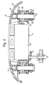
- Figur 2 eine Schnittansicht durch die vormontierte Einheit, bestehend aus Modul, Multifunktionsschaltereinheit und Führungsstiften, die in Figur 1 zu sehen ist,
- Figur 3 einen Schnitt durch das Fahrzeuglenkrad mit montierter Einheit aus Figur 2 bei nicht betätigter Hupe und
- Figur 4 einen Schnitt nach Figur 3 bei betätigter Hupe.
- FIG. 1 shows a plan view of a vehicle steering wheel according to the invention,
- FIG. 2 shows a sectional view through the preassembled unit, consisting of module, multifunction switch unit and guide pins, which can be seen in FIG. 1,
- 3 shows a section through the vehicle steering wheel with the mounted unit from FIG. 2 with the horn not actuated and
- 4 shows a section according to FIG. 3 with the horn actuated.
In Figur 1 ist ein Fahrzeuglenkrad dargestellt, das einen Lenkradkörper 10, ein
Gassackmodul 12 und an den Seiten unmittelbar an das Gassackmodul 12 angrenzende
Multifunktionsschaltereinheiten 14 zur Betätigung von Fahrzeugfunktionen,
wie Radio, Telefon, Bordcomputer und dergleichen hat. Der Lenkradkörper
besteht aus einem Lenkradskelett 16, das nur abschnittsweise dargestellt
ist, und einer Umschäumung 18. Das Gassackmodul 12 ist in Achsrichtung, also
in Figur 1 in Richtung senkrecht zur Zeichenebene, beweglich auf dem Lenkradkörper
10 gelagert, damit durch Drücken und Bewegen des Gassackmoduls 12 ein
Hupenkontakt auf der Rückseite des Moduls geschlossen wird und die Hupe
ertönt.In Figure 1, a vehicle steering wheel is shown, the
Das Gassackmodul 12 und die beiden Multifunktionsschaltereinheiten 14
sitzen so nahe nebeneinander, daß nur ein geringer Spalt 20 zwischen diesen
Teilen gebildet ist. Im übrigen bilden Gassackmodul 12 und Multifunktionsschaltereinheiten
14 eine in sich geschlossene, vormontierte Einheit, die in dem in
Figur 2 gezeigten Zustand komplett auf den Lenkradkörper 10 gesetzt und an ihm
montiert wird.The
In Figur 2 ist zu erkennen, daß das Gassackmodul eine Abdeckkappe 22 aus
Kunststoff hat, von der rückseitig auf jeder Seite, angrenzend an die Multifunktionsschaltereinheit,
hülsenförmige Vorsprünge 24 abstehen. In diese hülsenförmigen
Vorsprünge 24 sind die Führungsstifte 26 für die axiale Lagerung des
Gassackmoduls 12 eingepreßt. Die Führungsstifte 26 haben an ihrem freien, nicht
eingepreßten Ende einen seitlich vorstehenden Bund, der als Anschlag 28 bei der
Montage des Moduls wirkt. Auf den Führungsstiften 26 sitzen, angrenzend an den
Anschlag 28, Kunststoff-Lagerbuchsen 30, die radial äußere ringförmige Fortsätze
32 haben. Zwischen den Vorsprüngen 24 und den Lagerbuchsen 30 sitzen ferner
auf den Führungsstiften ohrenartige Vorsprünge 34 des Gehäuses 36 der Multifunktionsschaltereinheit
14, Druckfedern 38 und Lagerringe 40 für die Federn 38.
An den Lagerringen 40 kann optional ein topfförmiges Halteteil 41 zur Aufnahme
des Moduls 12 befestigt sein. Die Führungsstifte 26 können auch einstückig mit
dem Halteteil 41 ausgebildet sein.In Figure 2 it can be seen that the gas bag module from a
Dadurch, daß die Führungsstifte 26 in die Vorsprünge 24 eingepreßt sind und
mittels ringförmigen Absätzen 42 an ihrem Außenumfang auch formschlüssig am
Verlassen der Vorsprünge 24 gehindert sind, halten je zwei, einer Multifunktionsschaltereinheit
14 zugeordnete Führungsstifte 26, die Multifunktionsschaltereinheiten
14 am Modul 12 zur Bildung der vormontierten Einheit.In that the
Die Federn 38 sind wirkungsmäßig zwischen dem eingepreßten Ende der
Stifte 26 und damit zwischen Modul und Multifunktionsschaltereinheit 14
angeordnet und drücken die Multifunktionsschaltereinheiten 14 in die spätere
Einbaulage, also nach unten. Trotzdem sind aufgrund der Verschiebbarkeit von
Multifunktionsschaltereinheiten 14 und des Moduls 12 relativ zueinander Multifunktionsschaltereinheiten
und Modul in axialer Richtung bewegungsentkoppelt.
In radialer Richtung hingegen sind Multifunktionsschaltereinheiten 14 und Modul
12 über die Führungsstifte 26 fest miteinander gekoppelt, so daß nur ein geringer
Spalt 20 entsteht, der auch unabhängig von der axialen Position von Multifunktionseinheiten
14 und Modul 12 zueinander stets konstant ist, da diese Teile
auf derselben Führung sitzen.The
Wie zu erkennen ist, hat die in Figur 2 dargestellte vormontierte Einheit keine
Trägerbleche oder dergleichen, und die Einheit muß auch nicht zwingend auf ein
feststehendes Trägerblech am Lenkradkörper 10 montiert werden.As can be seen, the preassembled unit shown in FIG. 2 has none
Carrier sheets or the like, and the unit does not necessarily have to
fixed carrier plate can be mounted on the
Zur Montage selbst wird die in Figur 2 gezeigte Einheit von oben nach unten
auf den Lenkradkörper 10 gedrückt. In der Umschäumung sind Aufnahmen 43 für
die Führungsstifte 26 samt ihrer Lagerbuchsen 30 ausgebildet. Dem Wulst 32
komplementäre Ausnehmungen sind ebenfalls vorhanden, um nach dem Einpressen
einen Formschluß zwischen den Lagerbuchsen 30 und der Umschäumung 18
zu erzielen. Von der Unterseite des Moduls stehen Schnapphaken 45 ab, die durch
Öffnungen 44 in der Nabe des Lenkradskelettes 16 beim Montieren hindurchwandern
und anschließend verrasten, so daß eine Schnappverbindung gebildet
wird (siehe Figur 3). Die Schnapphaken 45 bilden zugleich einen axialen
Anschlag für das Modul, denn die Federn sind bestrebt, daß Modul nach oben zu
drücken. Damit - für die in Figur 3 gezeigte Ausgangsstellung, bei der noch keine
Hupenbetätigung vorliegt - auch die Schnapphaken 45 als axiale Anschläge für
das Modul wirken, sind die Anschläge 28 im Gegensatz zur Situation in Figur 2
(Modul noch nicht eingebaut) von den Lagerbuchsen 30 axial beabstandet. Die
Federn 38 drücken nicht nur das Modul 12 nach oben, sondern sie drücken die
Multifunktionsschaltereinheiten 14 auch nach unten, in die montierte Endstellung,
bei der die Multifunktionsschaltereinheiten an den Lagerbuchsen 30 und/oder dem
Lenkradkörper 10 anliegen.For assembly itself, the unit shown in Figure 2 is from top to bottom
pressed onto the
Durch diese definierte Stellung der Multifunktionsschaltereinheiten 14 kann es
selbst bei Aufbringen eines bezüglich Figur 3 nach unten gerichteten Druckes auf
die Multifunktionsschaltereinheiten 14 nicht zu einer versehentlichen Kontaktierung
von Hupenkontakten 52, 54 kommen.Due to this defined position of the
Beim Drücken des Moduls 12 nach unten zur Betätigung der Hupe muß das
Modul 12 gegen die Kraft der Federn 38 nach unten gedrückt werden (siehe Figur
4). Die Federn 38 dienen auch der Rückstellung des Moduls in die in Figur 3
gezeigte Ausgangsstellung, so daß auf der Rückseite des Moduls außer den
Führungsstiften 26 und den Haken 45 keine bislang üblichen Aufnahmen zur
Lagerung von Rückstellfedern vorgesehen sein müssen. Somit kann auch der
axiale Bauraum gering gehalten werden.When pressing the
Der Anschlag 28 muß nach der Montage des Moduls und der Multifunktionsschaltereinheit
im Lenkrad nicht zwingend vorhanden sein. Auch bis zur Montage
wäre denkbar, ohne den Anschlag 28 auszukommen. Beispielsweise könnte die
Feder 38 das Gassackmodul und die Multifunktionsschaltereinheit aneinander
halten. The
Alternativ könnten die Lagerbuchsen 30 auch durch die Multifunktionsschaltereinheit
gebildet werden.Alternatively, the bearing
Bei einem Lenkrad ohne Gassack-Modul hingegen könnte die Schnappverbindung
ohne weiteres weggelassen werden, so daß deren Eigenschaften nur
durch den Anschlag 28 erzielt werden.With a steering wheel without an airbag module, however, the snap connection could
are easily omitted, so that their properties only
can be achieved by the
Claims (10)
Applications Claiming Priority (2)
| Application Number | Priority Date | Filing Date | Title |
|---|---|---|---|
| DE20103890U DE20103890U1 (en) | 2001-03-06 | 2001-03-06 | Vehicle steering wheel |
| DE20103890U | 2001-03-06 |
Publications (3)
| Publication Number | Publication Date |
|---|---|
| EP1245462A2 true EP1245462A2 (en) | 2002-10-02 |
| EP1245462A3 EP1245462A3 (en) | 2004-03-31 |
| EP1245462B1 EP1245462B1 (en) | 2005-12-07 |
Family
ID=7953924
Family Applications (1)
| Application Number | Title | Priority Date | Filing Date |
|---|---|---|---|
| EP02004205A Expired - Lifetime EP1245462B1 (en) | 2001-03-06 | 2002-02-25 | Vehicle steering-wheel |
Country Status (4)
| Country | Link |
|---|---|
| US (1) | US6616180B2 (en) |
| EP (1) | EP1245462B1 (en) |
| DE (2) | DE20103890U1 (en) |
| ES (1) | ES2253459T3 (en) |
Cited By (2)
| Publication number | Priority date | Publication date | Assignee | Title |
|---|---|---|---|---|
| WO2005097556A1 (en) * | 2004-04-08 | 2005-10-20 | Takata-Petri Ag | Device for connection of an airbag module to a supporting vehicle component |
| CN111391769A (en) * | 2020-04-03 | 2020-07-10 | 广州小鹏汽车科技有限公司 | Vehicle interaction method and device based on steering wheel, vehicle and machine readable medium |
Families Citing this family (23)
| Publication number | Priority date | Publication date | Assignee | Title |
|---|---|---|---|---|
| DE20103891U1 (en) * | 2001-03-06 | 2002-04-11 | TRW Automotive Safety Systems GmbH & Co. KG, 63743 Aschaffenburg | vehicle steering wheel |
| US8433634B1 (en) | 2001-06-08 | 2013-04-30 | Genworth Financial, Inc. | Systems and methods for providing a benefit product with periodic guaranteed income |
| DE20112718U1 (en) | 2001-08-01 | 2001-12-20 | TRW Automotive Safety Systems GmbH & Co. KG, 63743 Aschaffenburg | Vehicle steering wheel |
| DE20116306U1 (en) * | 2001-10-05 | 2002-02-14 | TRW Automotive Safety Systems GmbH & Co. KG, 63743 Aschaffenburg | vehicle steering wheel |
| DE10152624A1 (en) * | 2001-10-25 | 2003-05-15 | Breed Automotive Tech | Horn technology for an airbag module |
| GB2390337A (en) * | 2002-07-02 | 2004-01-07 | Autoliv Dev | Steering wheel with airbag centrally and resiliently mounted |
| US7059631B2 (en) * | 2003-04-29 | 2006-06-13 | Toyoda Gosei Co., Ltd. | Method and apparatus for coupling a driver's side airbag to a steering wheel |
| US7077427B2 (en) * | 2003-07-16 | 2006-07-18 | Autoliv Asp, Inc. | Steering wheel assembly |
| SE526957C2 (en) * | 2003-12-09 | 2005-11-29 | Scania Cv Abp | vehicle steering wheel |
| US7556281B2 (en) * | 2004-03-16 | 2009-07-07 | Toyoda Gosei Co., Ltd. | Stamped airbag retention members and method of airbag assembly |
| KR100743303B1 (en) | 2004-08-28 | 2007-07-26 | 한국델파이주식회사 | Air Bag Module Including a Horn Switch Assembly |
| JP2006228700A (en) * | 2004-12-17 | 2006-08-31 | Tkj Kk | Horn switch device, air bag device, and steering wheel |
| DE102006058519B4 (en) | 2005-12-21 | 2018-09-27 | Trw Automotive Safety Systems Gmbh | Assembly with an airbag module |
| EP2089253B1 (en) * | 2006-11-13 | 2013-10-23 | Autoliv Development AB | An air-bag cover arrangement |
| KR20090050680A (en) * | 2007-11-16 | 2009-05-20 | 현대모비스 주식회사 | Steering assembly |
| US8256797B2 (en) * | 2008-09-16 | 2012-09-04 | Toyoda Gosei Co., Ltd. | Steering wheel with airbag device and method for assembling the same |
| US8939466B2 (en) | 2010-02-23 | 2015-01-27 | Judco Partnership, Llc | Airbag frame apparatus |
| US8491003B2 (en) * | 2010-02-23 | 2013-07-23 | Judco Manufacturing, Inc. | Airbag frame apparatus |
| JP5790311B2 (en) * | 2011-08-24 | 2015-10-07 | タカタ株式会社 | Mounting structure of air bag device for driver's seat and steering wheel |
| JP5780671B2 (en) * | 2011-10-31 | 2015-09-16 | タカタ株式会社 | Airbag device |
| KR102293578B1 (en) * | 2015-07-22 | 2021-08-25 | 현대모비스 주식회사 | Steering wheel air bag apparatus |
| DE102017102463A1 (en) * | 2017-02-08 | 2018-08-09 | Trw Automotive Safety Systems Gmbh | BEARING UNIT, STEERING WHEEL ASSEMBLY AND METHOD FOR MANUFACTURING A VEHICLE ASSEMBLY GROUP |
| EP3499076B1 (en) * | 2017-12-15 | 2021-03-31 | Vibracoustic Forsheda AB | A damper unit, a damper assembly, and a method for making a damper unit |
Family Cites Families (12)
| Publication number | Priority date | Publication date | Assignee | Title |
|---|---|---|---|---|
| EP0539869B1 (en) * | 1991-10-28 | 1997-05-28 | Toyoda Gosei Co., Ltd. | Steering wheel including air bag module |
| US5303952A (en) * | 1992-12-23 | 1994-04-19 | United Technologies Automotive, Inc. | Electric signalling in a supplemental vehicle restraint system |
| JP3734110B2 (en) * | 1996-06-21 | 2006-01-11 | 矢崎総業株式会社 | Steering module |
| JPH1035508A (en) * | 1996-07-24 | 1998-02-10 | Nippon Name Plate Kogyo Kk | Ornament serving also as horn button in air bag pad |
| EP0887239B1 (en) | 1997-06-24 | 2002-11-13 | Toyoda Gosei Co., Ltd. | Steering wheel having air bag module |
| DE29805207U1 (en) * | 1998-03-23 | 1998-06-04 | TRW Automotive Safety Systems GmbH, 63743 Aschaffenburg | Steering wheel with an airbag |
| DE29805210U1 (en) * | 1998-03-23 | 1998-06-04 | TRW Automotive Safety Systems GmbH, 63743 Aschaffenburg | Impact protection device |
| DE19819695C2 (en) * | 1998-05-02 | 2000-12-07 | Eaton Controls Gmbh | Steering wheel switch for a motor vehicle |
| DE19914653C1 (en) | 1999-03-31 | 2000-07-20 | Kostal Leopold Gmbh & Co Kg | Motor vehicle steering wheel has electronic module and bearer body with mounting section with arrangement for attaching to steering wheel in axial arrangement wrt. steering axis |
| DE29917214U1 (en) * | 1999-09-30 | 2000-02-17 | TRW Automotive Safety Systems GmbH & Co. KG, 63743 Aschaffenburg | Device for aligning two adjacent parts to be fastened to a vehicle one after the other |
| JP3707323B2 (en) * | 1999-12-10 | 2005-10-19 | 豊田合成株式会社 | Ornament mounting structure on steering wheel |
| DE20010543U1 (en) | 2000-06-14 | 2001-02-22 | TRW Automotive Safety Systems GmbH & Co. KG, 63743 Aschaffenburg | Multifunctional steering wheel |
-
2001
- 2001-03-06 DE DE20103890U patent/DE20103890U1/en not_active Expired - Lifetime
-
2002
- 2002-02-25 DE DE50205149T patent/DE50205149D1/en not_active Expired - Lifetime
- 2002-02-25 EP EP02004205A patent/EP1245462B1/en not_active Expired - Lifetime
- 2002-02-25 ES ES02004205T patent/ES2253459T3/en not_active Expired - Lifetime
- 2002-02-26 US US10/083,072 patent/US6616180B2/en not_active Expired - Fee Related
Non-Patent Citations (1)
| Title |
|---|
| None |
Cited By (5)
| Publication number | Priority date | Publication date | Assignee | Title |
|---|---|---|---|---|
| WO2005097556A1 (en) * | 2004-04-08 | 2005-10-20 | Takata-Petri Ag | Device for connection of an airbag module to a supporting vehicle component |
| US7331599B2 (en) | 2004-04-08 | 2008-02-19 | Takata-Petri Ag | Device for connection of an airbag module to a supporting vehicle component |
| CN100431880C (en) * | 2004-04-08 | 2008-11-12 | 高田-彼得里公开股份有限公司 | Device for connection of an airbag module to a supporting vehicle component |
| CN111391769A (en) * | 2020-04-03 | 2020-07-10 | 广州小鹏汽车科技有限公司 | Vehicle interaction method and device based on steering wheel, vehicle and machine readable medium |
| CN111391769B (en) * | 2020-04-03 | 2021-09-03 | 广州小鹏汽车科技有限公司 | Vehicle interaction method and device based on steering wheel, vehicle and machine readable medium |
Also Published As
| Publication number | Publication date |
|---|---|
| EP1245462A3 (en) | 2004-03-31 |
| US20020125698A1 (en) | 2002-09-12 |
| US6616180B2 (en) | 2003-09-09 |
| DE50205149D1 (en) | 2006-01-12 |
| ES2253459T3 (en) | 2006-06-01 |
| DE20103890U1 (en) | 2001-07-12 |
| EP1245462B1 (en) | 2005-12-07 |
Similar Documents
| Publication | Publication Date | Title |
|---|---|---|
| EP1245462B1 (en) | Vehicle steering-wheel | |
| EP1780425B1 (en) | Connection element | |
| EP0668187B1 (en) | Roller blind for station car | |
| EP1216893B1 (en) | Vehicle steering wheel | |
| EP2941779B1 (en) | Key module and slip-on element for a key module | |
| DE19511693A1 (en) | Motor vehicle steering column switch with angular spring | |
| EP0840336B1 (en) | Self-adjusting tappet-switch, in particular brake ligth switch | |
| DE69125135T2 (en) | Switch structure | |
| DE4117303C2 (en) | Horn control insert for a steering wheel | |
| EP1393972A2 (en) | Switching device for vehicle horn | |
| DE102017214017A1 (en) | Device for pressing a rack | |
| DE69619616T2 (en) | Hydraulic clutch actuator | |
| EP2266126A1 (en) | Pushbutton | |
| EP1609692A2 (en) | Gearing for a vehicle steering apparatus with a stationary center part | |
| WO2019238172A1 (en) | Closing device for a motor vehicle | |
| EP1088737A2 (en) | Sub-assembly with device for the alignment of two neighbouring parts | |
| DE2700691B2 (en) | Push button switch for an electronic clock | |
| EP1415870B1 (en) | Steering wheel | |
| EP1145922B1 (en) | Vehicle steering wheel with a movable airbag module | |
| DD226940A5 (en) | FRICTION CLUTCH | |
| DE69303480T2 (en) | THROUGH PRESSURE ACTIVATED CLUTCH MECHANISM WITH A CUP SPRING, IN PARTICULAR FOR CRATE VEHICLES | |
| DE2058688C3 (en) | Multi-stage diaphragm drive for controlling an actuator, in particular a valve | |
| WO2005080143A1 (en) | Housing for an airbag module | |
| DE102004051434A1 (en) | Airbag module housing for motor vehicle, has U-shaped or horseshoe shaped contact plate arranged on side of housing, and fixing unit that is arranged as snap-fit in area of steering wheel hub | |
| DE102019124387A1 (en) | Clutch mechanism with wear adjustment |
Legal Events
| Date | Code | Title | Description |
|---|---|---|---|
| PUAI | Public reference made under article 153(3) epc to a published international application that has entered the european phase |
Free format text: ORIGINAL CODE: 0009012 |
|
| AK | Designated contracting states |
Kind code of ref document: A2 Designated state(s): AT BE CH CY DE DK ES FI FR GB GR IE IT LI LU MC NL PT SE TR |
|
| AX | Request for extension of the european patent |
Free format text: AL;LT;LV;MK;RO;SI |
|
| PUAL | Search report despatched |
Free format text: ORIGINAL CODE: 0009013 |
|
| AK | Designated contracting states |
Kind code of ref document: A3 Designated state(s): AT BE CH CY DE DK ES FI FR GB GR IE IT LI LU MC NL PT SE TR |
|
| AX | Request for extension of the european patent |
Extension state: AL LT LV MK RO SI |
|
| RIC1 | Information provided on ipc code assigned before grant |
Ipc: 7B 60R 21/20 A Ipc: 7B 60Q 5/00 B Ipc: 7B 62D 1/04 B |
|
| 17P | Request for examination filed |
Effective date: 20040913 |
|
| AKX | Designation fees paid |
Designated state(s): DE ES FR GB IT |
|
| GRAP | Despatch of communication of intention to grant a patent |
Free format text: ORIGINAL CODE: EPIDOSNIGR1 |
|
| GRAS | Grant fee paid |
Free format text: ORIGINAL CODE: EPIDOSNIGR3 |
|
| GRAA | (expected) grant |
Free format text: ORIGINAL CODE: 0009210 |
|
| RAP1 | Party data changed (applicant data changed or rights of an application transferred) |
Owner name: TRW AUTOMOTIVE SAFETY SYSTEMS GMBH |
|
| AK | Designated contracting states |
Kind code of ref document: B1 Designated state(s): DE ES FR GB IT |
|
| PG25 | Lapsed in a contracting state [announced via postgrant information from national office to epo] |
Ref country code: GB Free format text: LAPSE BECAUSE OF FAILURE TO SUBMIT A TRANSLATION OF THE DESCRIPTION OR TO PAY THE FEE WITHIN THE PRESCRIBED TIME-LIMIT Effective date: 20051207 |
|
| REG | Reference to a national code |
Ref country code: GB Ref legal event code: FG4D Free format text: NOT ENGLISH |
|
| REF | Corresponds to: |
Ref document number: 50205149 Country of ref document: DE Date of ref document: 20060112 Kind code of ref document: P |
|
| REG | Reference to a national code |
Ref country code: ES Ref legal event code: FG2A Ref document number: 2253459 Country of ref document: ES Kind code of ref document: T3 |
|
| GBV | Gb: ep patent (uk) treated as always having been void in accordance with gb section 77(7)/1977 [no translation filed] |
Effective date: 20051207 |
|
| ET | Fr: translation filed | ||
| PLBE | No opposition filed within time limit |
Free format text: ORIGINAL CODE: 0009261 |
|
| STAA | Information on the status of an ep patent application or granted ep patent |
Free format text: STATUS: NO OPPOSITION FILED WITHIN TIME LIMIT |
|
| 26N | No opposition filed |
Effective date: 20060908 |
|
| PGFP | Annual fee paid to national office [announced via postgrant information from national office to epo] |
Ref country code: ES Payment date: 20070219 Year of fee payment: 6 |
|
| PGFP | Annual fee paid to national office [announced via postgrant information from national office to epo] |
Ref country code: IT Payment date: 20070529 Year of fee payment: 6 |
|
| REG | Reference to a national code |
Ref country code: ES Ref legal event code: FD2A Effective date: 20080226 |
|
| PG25 | Lapsed in a contracting state [announced via postgrant information from national office to epo] |
Ref country code: ES Free format text: LAPSE BECAUSE OF NON-PAYMENT OF DUE FEES Effective date: 20080226 |
|
| PG25 | Lapsed in a contracting state [announced via postgrant information from national office to epo] |
Ref country code: IT Free format text: LAPSE BECAUSE OF NON-PAYMENT OF DUE FEES Effective date: 20080225 |
|
| PGFP | Annual fee paid to national office [announced via postgrant information from national office to epo] |
Ref country code: DE Payment date: 20110228 Year of fee payment: 10 Ref country code: FR Payment date: 20110218 Year of fee payment: 10 |
|
| REG | Reference to a national code |
Ref country code: FR Ref legal event code: ST Effective date: 20121031 |
|
| REG | Reference to a national code |
Ref country code: DE Ref legal event code: R119 Ref document number: 50205149 Country of ref document: DE Effective date: 20120901 |
|
| PG25 | Lapsed in a contracting state [announced via postgrant information from national office to epo] |
Ref country code: FR Free format text: LAPSE BECAUSE OF NON-PAYMENT OF DUE FEES Effective date: 20120229 |
|
| PG25 | Lapsed in a contracting state [announced via postgrant information from national office to epo] |
Ref country code: DE Free format text: LAPSE BECAUSE OF NON-PAYMENT OF DUE FEES Effective date: 20120901 |