EP1245456A1 - Impact absorber - Google Patents
Impact absorber Download PDFInfo
- Publication number
- EP1245456A1 EP1245456A1 EP02005951A EP02005951A EP1245456A1 EP 1245456 A1 EP1245456 A1 EP 1245456A1 EP 02005951 A EP02005951 A EP 02005951A EP 02005951 A EP02005951 A EP 02005951A EP 1245456 A1 EP1245456 A1 EP 1245456A1
- Authority
- EP
- European Patent Office
- Prior art keywords
- hollow body
- fastening
- fastening surface
- jacket
- impact
- Prior art date
- Legal status (The legal status is an assumption and is not a legal conclusion. Google has not performed a legal analysis and makes no representation as to the accuracy of the status listed.)
- Granted
Links
Images


Classifications
-
- B—PERFORMING OPERATIONS; TRANSPORTING
- B60—VEHICLES IN GENERAL
- B60R—VEHICLES, VEHICLE FITTINGS, OR VEHICLE PARTS, NOT OTHERWISE PROVIDED FOR
- B60R19/00—Wheel guards; Radiator guards, e.g. grilles; Obstruction removers; Fittings damping bouncing force in collisions
- B60R19/02—Bumpers, i.e. impact receiving or absorbing members for protecting vehicles or fending off blows from other vehicles or objects
- B60R19/24—Arrangements for mounting bumpers on vehicles
- B60R19/26—Arrangements for mounting bumpers on vehicles comprising yieldable mounting means
- B60R19/34—Arrangements for mounting bumpers on vehicles comprising yieldable mounting means destroyed upon impact, e.g. one-shot type
-
- F—MECHANICAL ENGINEERING; LIGHTING; HEATING; WEAPONS; BLASTING
- F16—ENGINEERING ELEMENTS AND UNITS; GENERAL MEASURES FOR PRODUCING AND MAINTAINING EFFECTIVE FUNCTIONING OF MACHINES OR INSTALLATIONS; THERMAL INSULATION IN GENERAL
- F16F—SPRINGS; SHOCK-ABSORBERS; MEANS FOR DAMPING VIBRATION
- F16F7/00—Vibration-dampers; Shock-absorbers
- F16F7/12—Vibration-dampers; Shock-absorbers using plastic deformation of members
-
- B—PERFORMING OPERATIONS; TRANSPORTING
- B60—VEHICLES IN GENERAL
- B60R—VEHICLES, VEHICLE FITTINGS, OR VEHICLE PARTS, NOT OTHERWISE PROVIDED FOR
- B60R21/00—Arrangements or fittings on vehicles for protecting or preventing injuries to occupants or pedestrians in case of accidents or other traffic risks
- B60R2021/0002—Type of accident
- B60R2021/0023—Offset collision
Definitions
- the invention relates to an impact damper for motor vehicles for energy consumption in the event of a collision between the motor vehicle and an obstacle Features of the preamble of claim 1 or the subordinate Claim 4.
- Impact absorbers of the type in question serve to protect the occupants of a motor vehicle in a collision, in particular in a front, rear or Side collision in that it is the one released in such a collision Absorb energy as much as possible through deformation and to the Do not pass on the passenger compartment or only pass it on to a significantly reduced extent.
- Such impact dampers are primarily used between those connected to the passenger compartment Vehicle side members and the transverse bumper side Cross beams, the so-called bumper cross beams.
- the primary task of the bumper cross member is in the event of a collision a train connection between the right and left side of the vehicle body to ensure optimal occupant protection.
- Impact dampers between the vehicle side members and the bumper cross members must therefore have a tensile connection between the involved carriers as well as the desired energy consumption by deformation.
- impact dampers are entirely considerable demands on material and design.
- Impact dampers are usually made of metal, especially steel, if necessary also made of aluminum, magnesium or corresponding alloys. Very different types of steel, including high-strength steels in the corresponding Shapes are often used here.
- Impact dampers for motor vehicles for energy absorption are also for side collisions deployed within the structures, commonly known as side impact protection be designated.
- the area of the B-pillar and if necessary the C-pillar could be interesting for the arrangement of the impact absorber.
- impact dampers of the type in question are also inside the passenger compartment can be used, for example as a support arrangement for knee pads.
- the force-displacement curve is essential for the function and effect of an impact damper vital.
- the beginning of deformation is of considerable importance.
- very complex movements of the bumper cross member on which is taken into account when designing the impact damper should be.
- the fastening surfaces are parallel to one another aligned, which is often the case, the adaptation to the mostly in a complicated manner, the curved shape of the bumper cross member, the strak, done in another way.
- the Bumper cross member has different cross sections or that wedge-shaped / arc-shaped Compensating elements between the bumper cross member and the impact damper inserted and welded or screwed (EP 0 718 157 A1, EP 0 718 158 A1).
- the angular position between the bumper cross member and the front surface of the impact absorber changes in a laterally offset front collision, that the bumper crossmember is initially strongly depressed in the middle is and only then a substantially uniform deformation over the full width of the impact area in the longitudinal direction.
- It can Known impact absorbers that occur transversely to the longitudinal direction force component occurring so large, especially at the beginning of the front collision is that the bumper cross member tears off the impact damper or the impact damper kinked sideways. The impact damper thus loses at Beginning of the front collision its effect, which only afterwards to protect the passenger compartment.
- the teaching is therefore based on the problem of an impact damper for motor vehicles to indicate the properties regarding collision, especially in a laterally offset front collision.
- the arcuate in accordance with the Strak running bumper cross member especially with a laterally offset Front collision on the inside of the motor vehicle body Side that is the first or the most powerful in the event of a collision is deformed in a targeted manner in the longitudinal direction without the main part the impact damper, namely the hollow body as such, already deformed becomes.
- the lead path realized according to the invention it is guaranteed that in a laterally offset front collision initially at an acute angle to the first mounting surface second mounting surface up to parallelism or approximately parallelism aligns with the first mounting surface.
- the total shock absorber So it stops at the beginning of the deformation and its deformation in the longitudinal direction for the purpose of energy absorption only begins when the bumper cross member is particularly stressed, towards the center the area of the motor vehicle body is considerably deformed inwards Has.
- the function of the shock absorber remains with a laterally offset one Front collision preserved, the passenger compartment remains optimally protected.
- the second mounting surface is So the contact surface on the bumper cross member shaped so that the Mating surface on the bumper cross member here without problems in a considerable Angular range can come to the plant.
- the bolt bearing realized here becomes a bearing on a spherical segment or similarly arcuate cap reached. You can easily screw the bumper cross beam here axially or weld. This is of particular importance Teach also the fact that at the foot of the cap in the transition to Hollow body is formed or can be a kink, which is the asymmetrical Buckling while maintaining the hollow body unchanged a laterally offset front collision in a similar manner as previously explained allowed. This asymmetrical buckling or sinking of the cap into the The body of the hollow body as a whole leads to the firm connection of the Bumper cross member with the impact absorber does not tear open, but itself in the event of a laterally offset front collision.
- Impact absorbers are the subject of the subclaims.
- the subclaims are also more preferred in connection with the explanation Embodiments discussed further with reference to the drawing.
- the Impact absorber 1 intended for use in motor vehicles, specifically for Energy consumption when the motor vehicle collides with an obstacle.
- the impact damper 1 can at various points in the body of the Motor vehicle installed and should be the existing in a collision Absorb kinetic energy as much as possible to work it in deformation implement so that the passenger compartment of the vehicle body is affected as little as possible. On the executions the general part of the description may refer to this again become.
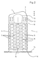
- the exemplary embodiment shown describes, just as an example, one Impact absorber 1 using the example of an insert for energy absorption in a Front collision of the motor vehicle with an obstacle, namely used between a front bumper cross member 2 and one in the vehicle longitudinal direction extending vehicle side member connected to the passenger compartment 3 or its end face.
- this vehicle side member 3 only indicated by dashed lines to the installation position of the impact damper 1 to make it easier to understand.
- the is concealing Front of the bumper cross member 2 has been omitted.
- the impact damper 1 regularly consists of a metal, in particular Steel, possibly also made of an aluminum alloy.
- the impact damper 1 shows the impact damper 1 for absorbing energy in the event of a collision of the motor vehicle with an obstacle.
- Fig. 2 in context with Fig. 1, it can be seen that the impact damper 1 is a metal existing, defining a longitudinal direction of the impact damper 1 has cylindrical hollow body 4.
- Preferred embodiments of this cylindrical hollow body 4 are otherwise the subject of older, not previously published Patent applications (100 00 285.4, 100 00 286.2) to which may be referred here to avoid repetitions.
- the Hollow body 4 has a defined compression of the hollow body 4 Deformation beads in the jacket in the longitudinal direction when force is applied 5 on.
- first fastening surface 6 On the hollow body 4 there is an essentially transversely oriented, first fastening surface 6 provided at one end for attachment to a vehicle side member 3 or another structural component of the motor vehicle body.
- second end of the hollow body 4 there is a second fastening surface 7 for fastening the impact damper 1 on a counter surface 8 of the bumper cross member 2 or one other structural component of the motor vehicle body.
- the hollow body 4 is essentially closed at the second end.
- the one located there second fastening surface 7 allows the bumper cross member to be fastened 2 on the hollow body 4 with at an acute angle to the first mounting surface 6 running counter surface 8.
- FIG. 1, 2 and 3 of an inventive Impact absorber 1 is now characterized in that the second mounting surface 7 as an inclined face corresponding to the acute angle of the hollow body 4 is formed, the hollow body 4 is the second fastening surface 7 forming, roof-shaped beveled end portion 9 and approximately below that which is most forward in the longitudinal direction Edge of the second fastening surface 7, in FIG. 1 the one on the top right Edge, on the other hand, set back in the longitudinal direction by a certain distance A, A kink 10 is formed in the jacket of the hollow body. This Kink 10 is designed such that upon initial application of force At this point, a compression takes place here, namely in the essentially without compression of the hollow body 4 in the rest.
- Fig. 3 shows a somewhat more pronounced formation of the kink 10 in one another embodiment.
- the determined distance A corresponds approximately to the distance of the furthest front edge from furthest back Edge of the second fastening surface 7.
- the kink 10 is on the jacket of the Hollow body 4 in the end section 9 extending over a section executed.
- a bead In the embodiment shown in Fig. 3 one can see such a bead, however, also in a modified form on the opposite one Edge.
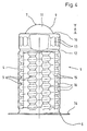
- Fig. 4 shows a further, alternative embodiment of an inventive Impact absorber 1.
- the impact damper 1 here has an arcuate shape, in particular spherical section-shaped cap 11 which the hollow body 4 on closes the second end and forms the second fastening surface 7 there.
- these Cap 11 basically an arbitrary attachment of the counter surface 8th on the hollow body 4, that is to say the function of that in the prior art known pivot pin met, without having its disadvantages.
- connection can be made by welding or by screwing will be realized.
- FIG. 4 Impact absorber 1
- a corresponding one Kink 10 is realized.
- the kink 10 is designed such that at the beginning Applying force at this point initially essentially compresses here otherwise without upsetting the hollow body 4.
- the in Fig. 4 example shows that the kink 10 at the foot of the cap 11 lies within the circumference of the shell of the hollow body 4. This leads the kink 10 so that the cap 11 at the presupposed asymmetrical application of force in the longitudinal direction at the beginning of the deformation overall, so to speak, pressed into the interior of the hollow body 1 becomes. In this way it is particularly useful here the lead path for the function according to the invention is realized.
- the hollow body 4 has an end section 9, which in this case forms the cap 11.
- the end portion 9 of the hollow body 4 from the hollow body 4 in the rest is offset by a completely surrounding bead 12.
- the jacket of the hollow body 4 in the end section 9, namely between the kink 10 and the bead 12, with extending in the longitudinal direction Stiffening ribs 13 is provided.
- the end section 9 of the hollow body 4 overall a relatively stiff in the longitudinal direction, thus only forms a compressible area under high forces into which the roof-shaped beveled end is pressed before the total Hollow body 4 is otherwise in the longitudinal direction, that is, axially compressed.
- the illustrated and preferred exemplary embodiments show, moreover, that, as already known in the prior art, the hollow body 4 for training the first mounting surface 6 an outwardly projecting mounting flange 14 has.
- the hollow body 4 at least three evenly distributed over its circumference and in the longitudinal direction extending web-shaped areas 15 and between adjacent web-shaped regions 15 in the jacket of the hollow body 4 at least three parallel, extending in the circumferential direction and to the interior of the hollow body
- Directional stiffening beads 5 are arranged such that - in axial Direction seen - between adjacent stiffening beads 5 after result in domed areas 16.
- the vaulted ones adjacent on the circumference Areas 16 enclose the in the illustrated embodiment Longitudinal axis of the hollow body 4 helically. An alternative can even with a circular design.
- cylindrical hollow body 4 does not necessarily mean a circular cylindrical design, also other cross-sections, oval, square, polygonal cross-sections are also conceivable if this is in practice proven in experiments.
Abstract
Description
Die Erfindung betrifft einen Aufpralldämpfer für Kraftfahrzeuge zur Energieaufnahme
bei einer Kollision des Kraftfahrzeugs mit einem Hindernis mit den
Merkmalen des Oberbegriffs von Anspruch 1 bzw. des nebengeordneten
Anspruchs 4.The invention relates to an impact damper for motor vehicles for energy consumption
in the event of a collision between the motor vehicle and an obstacle
Features of the preamble of
Aufpralldämpfer der in Rede stehenden Art dienen dem Schutz der Insassen eines Kraftfahrzeugs bei einer Kollision, insbesondere bei einer Front-, Heckoder Seitenkollision dadurch, daß sie die bei einer solchen Kollision freiwerdende Energie durch Verformung so weit wie möglich aufnehmen und an die Fahrgastzelle nicht oder nur stark reduziert weitergeben. Solche Aufpralldämpfer werden primär eingesetzt zwischen den mit der Fahrgastzelle verbundenen Fahrzeuglängsträgern und den quer dazu verlaufenden stoßstangenseitigen Querträgern, den sogenannten Stoßfängerquerträgem. Die vorrangige Aufgabe des Stoßfängerquerträgers ist es dabei, bei einer Kollision einen Zugverbund zwischen der rechten und der linken Seite der Fahrzeugkarosserie sicherzustellen, um so einen optimalen Insassenschutz zu gewährleisten. Die Aufpralldämpfer zwischen den Fahrzeuglängsträgern und den Stoßfängerquerträgem müssen also eine zugfeste Verbindung zwischen den beteiligten Trägern ebenso realisieren wie die gewünschte Energieaufnahme durch Verformung. Dadurch werden an solche Aufpralldämpfer ganz erhebliche Anforderungen an Material und Auslegung gestellt. Derartige Aufpralldämpfer bestehen regelmäßig aus Metall, insbesondere aus Stahl, gegebenenfalls auch aus Aluminium, Magnesium oder entsprechenden Legierungen. Ganz unterschiedliche Stahlsorten, auch hochfeste Stähle in entsprechender Formgebung werden hier gern verwendet.Impact absorbers of the type in question serve to protect the occupants of a motor vehicle in a collision, in particular in a front, rear or Side collision in that it is the one released in such a collision Absorb energy as much as possible through deformation and to the Do not pass on the passenger compartment or only pass it on to a significantly reduced extent. Such impact dampers are primarily used between those connected to the passenger compartment Vehicle side members and the transverse bumper side Cross beams, the so-called bumper cross beams. The The primary task of the bumper cross member is in the event of a collision a train connection between the right and left side of the vehicle body to ensure optimal occupant protection. The impact absorbers between the vehicle side members and the bumper cross members must therefore have a tensile connection between the involved carriers as well as the desired energy consumption by deformation. As a result, such impact dampers are entirely considerable demands on material and design. such Impact dampers are usually made of metal, especially steel, if necessary also made of aluminum, magnesium or corresponding alloys. Very different types of steel, including high-strength steels in the corresponding Shapes are often used here.
Aufpralldämpfer für Kraftfahrzeuge zur Energieaufnahme sind auch für Seitenkollisionen einzusetzen, innerhalb der Strukturen, die gemeinhin als Seitenaufprallschutz bezeichnet werden. Auch der Bereich der B-Säule und ggf. der C-Säule könnte für die Anordnung des Aufpralldämpfers interessant sein. Schließlich sind Aufpralldämpfer der in Rede stehenden Art auch innerhalb der Fahrgastzelle einsetzbar, beispielsweise als Trägeranordnung für Kniepolster. Impact dampers for motor vehicles for energy absorption are also for side collisions deployed within the structures, commonly known as side impact protection be designated. The area of the B-pillar and if necessary the C-pillar could be interesting for the arrangement of the impact absorber. Finally, impact dampers of the type in question are also inside the passenger compartment can be used, for example as a support arrangement for knee pads.
Im folgenden wird das Konzept der Erfindung anhand von in Fahrzeuglängsrichtung eingesetzten Aufpralldämpfern erläutert, die für Front- und Heckkollisionen relevant sind. Es ist zu berücksichtigen, daß Aufpralldämpfer für andere Anwendungen in entsprechender Weise angepaßt von der Lehre der Erfindung mit umfaßt werden. Aus diesem Grund wird auch immer von Stoßfängerquerträger o. dgl. und von Fahrzeuglängsträger o. dgl. die Rede sein, da entsprechende Tragstrukturen für andere Anordnungen an der Fahrzeugkarosserie mit umfaßt sein sollen.The following is the concept of the invention based on in the vehicle longitudinal direction used shock absorbers explained for front and Rear collisions are relevant. It should be borne in mind that impact dampers adapted accordingly for other applications from teaching of the invention are included. For this reason, is always from Bumper cross member or the like and of vehicle side members or the like be there corresponding support structures for other arrangements on the vehicle body should be included.
Für Funktion und Wirkung eines Aufpralldämpfers ist der Kraft-Weg-Verlauf von entscheidender Bedeutung. Insbesondere dem Deformationsbeginn kommt dabei erhebliche Bedeutung zu. Insbesondere bei einer seitlich versetzten Frontkollision treten sehr komplexe Bewegungen des Stoßfängerquerträgers auf, die bei Konzeption des Aufpralldämpfers berücksichtigt werden sollten.The force-displacement curve is essential for the function and effect of an impact damper vital. In particular the beginning of deformation is of considerable importance. Especially with a laterally offset Front collision occurs very complex movements of the bumper cross member on, which is taken into account when designing the impact damper should be.
Sind bei bekannten Aufpralldämpfern die Befestigungsflächen parallel zueinander ausgerichtet, was häufig der Fall ist, so muß die Anpassung an den meist in komplizierter Weise bogenförmigen Verlauf des Stoßfängerquerträgers, den Strak, auf anderer Weise erfolgen. Bekannt ist es dabei, daß der Stoßfängerquerträger unterschiedliche Querschnitte aufweist oder daß keilförmige/bogenförmige Ausgleichselemente zwischen dem Stoßfängerquerträger und dem Aufpralldämpfer eingesetzt und verschweißt oder verschraubt werden (EP 0 718 157 A1, EP 0 718 158 A1). Bekannt ist es aber auch bereits, einen Aufpralldämpfer für Kraftfahrzeuge zu realisieren, bei dem die Befestigungsfläche für den Stoßfängerquerträger und die Befestigungsfläche für den Fahrzeuglängsträger nicht parallel zueinander ausgerichtet, sondern in einem spitzen Winkel, bevorzugt einem Winkel von etwa 15°, zueinander ausgerichtet sind (DE 198 29 566 A1). Bei dieser Konstruktion hat man also den Strak des Stoßfängerquerträgers bereits im Aufpralldämpfer selbst berücksichtigt.In known impact absorbers, the fastening surfaces are parallel to one another aligned, which is often the case, the adaptation to the mostly in a complicated manner, the curved shape of the bumper cross member, the strak, done in another way. It is known that the Bumper cross member has different cross sections or that wedge-shaped / arc-shaped Compensating elements between the bumper cross member and the impact damper inserted and welded or screwed (EP 0 718 157 A1, EP 0 718 158 A1). But it is already known to realize an impact damper for motor vehicles, in which the mounting surface for the bumper cross member and the mounting surface for the vehicle side member not aligned parallel to each other, but in an acute angle, preferably an angle of about 15 ° to each other are aligned (DE 198 29 566 A1). So with this construction you have the strake of the bumper cross member is already taken into account in the impact absorber itself.
Bekannt ist es auch, einen Aufpralldämpfer mit dem Stoßfängerquerträger über eine Bolzenlagerung gelenkig zu verbinden (DE 198 32 114 A1). Das hat den Vorteil, daß die Winkelstellung zwischen dem Stoßfängerquerträger und der vorderen Stirnseite des Aufpralldämpfers nicht im voraus bestimmt sein muß und sich insbesondere auch im Kollisionsfall verändern kann, ohne daß der Verbund des Stoßfängerquerträgers mit dem Aufpralldämpfer aufgehoben wird. Eine solche Bolzen-Lagerung ist aber wiederum befestigungstechnisch und von der Steifigkeit des Stoßfängerquerträgers her problematisch. Außerdem gelingt die Krafteinleitung über den Bolzen in den Aufpralldämpfer nicht optimal.It is also known to have an impact absorber with the bumper cross member to be connected in an articulated manner via a pin bearing (DE 198 32 114 A1). The has the advantage that the angular position between the bumper cross member and the front end of the impact damper is not determined in advance must be and can change, especially in the event of a collision, without that the bond between the bumper crossmember and the impact absorber is removed becomes. Such a bolt bearing is again fastening technology and problematic from the rigidity of the bumper cross member. In addition, the force is introduced into the impact damper via the bolt not optimal.
Die Winkelstellung zwischen Stoßfängerquerträger und Stirnfläche des Aufpralldämpfers verändert sich bei einer seitlich versetzten Frontkollision dadurch, daß der Stoßfängerquerträger zunächst in der Mitte stark eingedrückt wird und danach erst eine im wesentlichen gleichmäßige Verformung über die volle Breite des Auftreffbereichs in Längsrichtung erfolgt. Dabei kann es bei bekannten Aufpralldämpfern vorkommen, daß die quer zur Längsrichtung auftretende Kraftkomponente gerade bei Beginn der Frontkollision so groß ist, daß der Stoßfängerquerträger vom Aufpralldämpfer abreißt oder der Aufpralldämpfer seitlich wegknickt. Damit verliert der Aufpralldämpfer bereits bei Beginn der Frontkollision seine Wirkung, die an sich erst im Anschluß daran zum Schutze der Fahrgastzelle einsetzen soll.The angular position between the bumper cross member and the front surface of the impact absorber changes in a laterally offset front collision, that the bumper crossmember is initially strongly depressed in the middle is and only then a substantially uniform deformation over the full width of the impact area in the longitudinal direction. It can Known impact absorbers that occur transversely to the longitudinal direction force component occurring so large, especially at the beginning of the front collision is that the bumper cross member tears off the impact damper or the impact damper kinked sideways. The impact damper thus loses at Beginning of the front collision its effect, which only afterwards to protect the passenger compartment.
Der Lehre liegt somit das Problem zugrunde, einen Aufpralldämpfer für Kraftfahrzeuge anzugeben, der hinsichtlich der Eigenschaften im Kollisonsfall, insbesondere bei einer seitlich versetzten Frontkollision, optimiert ist.The teaching is therefore based on the problem of an impact damper for motor vehicles to indicate the properties regarding collision, especially in a laterally offset front collision.
Das zuvor aufgezeigte Problem ist bei dem Aufpralldämpfer mit den Merkmalen
des Oberbegriffs von Anspruch 1 durch die Merkmale des kennzeichnenden
Teils von Anspruch 1 gelöst. Eine nebengeordnete Lösung gibt Anspruch
4.The problem outlined above is with the crash cushion with the features
of the preamble of
Erfindungsgemäß wird erreicht, daß der entsprechend dem Strak bogenförmig verlaufende Stoßfängerquerträger insbesondere bei einer seitlich versetzten Frontkollision an der zur Innenseite der Kraftfahrzeugkarosserie gerichteten Seite, die im Kollisionsfall als erste bzw. zu Beginn am stärksten mit Kraft beaufschlagt wird, gezielt in Längsrichtung verformt wird, ohne daß der Hauptteil des Aufpralldämpfers, nämlich der Hohlkörper als solcher, bereits verformt wird. Mit anderen Worten, aufgrund des erfindungsgemäß realisierten Vorlaufwegs ist gewährleistet, daß bei einer seitlich versetzten Frontkollision die zunächst in einem spitzen Winkel zur ersten Befestigungsfläche stehende zweite Befestigungsfläche sich bis zur Parallelität oder annähernder Parallelität mit der ersten Befestigungsfläche ausrichtet. Der Aufpralldämpfer insgesamt bleibt also zunächst bei Deformationsbeginn stehen und seine Verformung in Längsrichtung zum Zwecke der Energieaufnahme beginnt erst dann, wenn sich der Stoßfängerquerträger im besonders beanspruchten, zur Mitte der Kraftfahrzeugkarosserie liegenden Bereich erheblich nach innen verformt hat. Die Funktion des Aufpralldämpfers bleibt auch bei einer seitlich versetzten Frontkollision erhalten, die Fahrgastzelle bleibt optimal geschützt.According to the invention it is achieved that the arcuate in accordance with the Strak running bumper cross member, especially with a laterally offset Front collision on the inside of the motor vehicle body Side that is the first or the most powerful in the event of a collision is deformed in a targeted manner in the longitudinal direction without the main part the impact damper, namely the hollow body as such, already deformed becomes. In other words, on the basis of the lead path realized according to the invention it is guaranteed that in a laterally offset front collision initially at an acute angle to the first mounting surface second mounting surface up to parallelism or approximately parallelism aligns with the first mounting surface. The total shock absorber So it stops at the beginning of the deformation and its deformation in the longitudinal direction for the purpose of energy absorption only begins when the bumper cross member is particularly stressed, towards the center the area of the motor vehicle body is considerably deformed inwards Has. The function of the shock absorber remains with a laterally offset one Front collision preserved, the passenger compartment remains optimally protected.
Bei der nebengeordneten Alternative der Lehre ist die zweite Befestigungsfläche, also die Anlagefläche am Stoßfängerquerträger so geformt, daß die Gegenfläche am Stoßfängerquerträger hier unproblematisch in einem erheblichen Winkelbereich zur Anlage kommen kann. Statt der im Stand der Technik hier realisierten Bolzen-Lagerung wird eine Lagerung an einer kugelabschnittförmigen oder in ähnlicher Weise bogenförmig ausgebildeten Kappe erreicht. Man kann den Stoßfängerquerträger ohne weiteres hier axial verschrauben oder verschweißen. Besonderer Bedeutung kommt bei dieser Lehre ebenfalls der Tatsache zu, daß am Fuß der Kappe im Übergang zum Hohlkörper eine Knickstelle ausgebildet ist bzw. sein kann, die das asymmetrische Einknicken bei zunächst unverändertem Erhalt des Hohlkörpers bei einer seitlich versetzten Frontkollision in ähnlicher Weise wie zuvor erläutert erlaubt. Dieses asymmetrische Einknicken bzw. Einsenken der Kappe in den Korpus des Hohlkörpers insgesamt führt dazu, daß die feste Verbindung des Stoßfängerquerträgers mit dem Aufpralldämpfer nicht aufreißt, sondern selbst bei einer seitlich versetzten Frontkollision erhalten bleibt.In the secondary alternative to teaching, the second mounting surface is So the contact surface on the bumper cross member shaped so that the Mating surface on the bumper cross member here without problems in a considerable Angular range can come to the plant. Instead of that in the prior art The bolt bearing realized here becomes a bearing on a spherical segment or similarly arcuate cap reached. You can easily screw the bumper cross beam here axially or weld. This is of particular importance Teach also the fact that at the foot of the cap in the transition to Hollow body is formed or can be a kink, which is the asymmetrical Buckling while maintaining the hollow body unchanged a laterally offset front collision in a similar manner as previously explained allowed. This asymmetrical buckling or sinking of the cap into the The body of the hollow body as a whole leads to the firm connection of the Bumper cross member with the impact absorber does not tear open, but itself in the event of a laterally offset front collision.
Bevorzugte Ausgestaltungen und Weiterbildungen der erfindungsgemäßen Aufpralldämpfer sind Gegenstand der Unteransprüche. Die Unteransprüche werden im übrigen auch im Zusammenhang mit der Erläuterung bevorzugter Ausführungsbeispiele anhand der Zeichnung weiter diskutiert.Preferred refinements and developments of the invention Impact absorbers are the subject of the subclaims. The subclaims are also more preferred in connection with the explanation Embodiments discussed further with reference to the drawing.
Im folgenden wird die Erfindung anhand einer lediglich Ausführungsbeispiel darstellenden Zeichnung näher erläutert. In der Zeichnung zeigt
- Fig. 1
- in einer Prinzipdarstellung einen Ausschnitt eines Stoßfängerquerträgers an einer Kraftfahrzeugkarosserie in Verbindung mit einem Aufpralldämpfer und einem Fahrzeuglängsträger,
- Fig. 2
- ein erstes Ausführungsbeispiel eines erfindungsgemäßen Aufpralldämpfers,
- Fig. 3
- ein zweites Ausführungsbeispiel eines erfindungsgemäßen Aufpralldämpfers,
- Fig. 4
- ein drittes Ausführungsbeispiel eines erfindungsgemäßen Aufpralldämpfers.
- Fig. 1
- a schematic representation of a section of a bumper cross member on a motor vehicle body in connection with an impact damper and a vehicle side member,
- Fig. 2
- a first embodiment of an impact damper according to the invention,
- Fig. 3
- a second embodiment of an impact damper according to the invention,
- Fig. 4
- a third embodiment of an impact damper according to the invention.
Wie im allgemeinen Teil der Beschreibung bereits erläutert worden ist, ist der
Aufpralldämpfer 1 für den Einsatz in Kraftfahrzeugen bestimmt, und zwar zur
Energieaufnahme bei einer Kollision des Kraftfahrzeugs mit einem Hindernis.
Der Aufpralldämpfer 1 kann an verschiedenen Stellen in der Karosserie des
Kraftfahrzeugs eingebaut werden und soll die bei einer Kollision vorhandene
Bewegungsenergie soweit wie möglich aufnehmen, um diese in Verformungsarbeit
umzusetzen, so daß die Fahrgastzelle der Fahrzeugkarosserie
möglichst wenig in Mitleidenschaft gezogen wird. Auf die Ausführungen
dazu im allgemeinen Teil der Beschreibung darf hier nochmals hingewiesen
werden.As has already been explained in the general part of the description, the
Impact absorber 1 intended for use in motor vehicles, specifically for
Energy consumption when the motor vehicle collides with an obstacle.
The
Das dargestellte Ausführungsbeispiel beschreibt, eben nur beispielhaft, einen
Aufpralldämpfer 1 am Beispiel eines Einsatzes zur Energieaufnahme bei einer
Frontkollision des Kraftfahrzeugs mit einem Hindernis, und zwar eingesetzt
zwischen einem frontseitigen Stoßfängerquerträger 2 und einem in Fahrzeuglängsrichtung
verlaufenden, mit der Fahrgastzelle verbundenen Fahrzeuglängsträger
3 bzw. dessen Stirnseite. In Fig. 1 ist dieser Fahrzeuglängsträger
3 lediglich gestrichelt angedeutet, um die Einbaulage des Aufpralldämpfers
1 besser verständlich zu machen. Außerdem ist die verdeckende
Vorderseite des Stoßfängerquerträgers 2 weggelassen worden.The exemplary embodiment shown describes, just as an example, one
Impact absorber 1 using the example of an insert for energy absorption in a
Front collision of the motor vehicle with an obstacle, namely used
between a front
Der Aufpralldämpfer 1 besteht regelmäßig aus einem Metall, insbesondere aus
Stahl, gegebenenfalls auch aus einer Aluminiumlegierung. The
Fig. 1 zeigt den Aufpralldämpfer 1 zur Energieaufnahme bei einer Kollision
des Kraftfahrzeugs mit einem Hindernis. Betrachtet man Fig. 2 im Zusammenhang
mit Fig. 1, so erkennt man, daß der Aufpralldämpfer 1 einen aus Metall
bestehenden, eine Längsrichtung des Aufpralldämpfer 1 definierenden
zylinderischen Hohlkörper 4 aufweist. Bevorzugte Ausgestaltungen dieses
zylinderischen Hohlkörpers 4 sind im übrigen Gegenstand älterer, nicht vorveröffentlichter
Patentanmeldungen (100 00 285.4, 100 00 286.2), auf die
hier zur Vermeidung von Wiederholungen verwiesen werden darf. Der
Hohlkörper 4 weist zur Realisierung einer definierten Stauchung des Hohlkörpers
4 bei Kraftbeaufschlagung in Längsrichtung im Mantel Verformungssicken
5 auf. Im einzelnen ist dazu auf die zuvor genannten, nicht vorveröffentlichten
Patentanmeldungen zu verweisen.1 shows the
Am Hohlkörper 4 ist eine im wesentlichen quer ausgerichtete, erste Befestigungsfläche
6 an einem Ende vorgesehen, zur Befestigung an einem Fahrzeuglängsträger
3 oder einem anderen Strukturbauelement der Kraftfahrzeugkarosserie.
Am gegenüberliegenden, zweiten Ende des Hohlkörpers 4
befindet sich eine zweite Befestigungsfläche 7 zur Befestigung des Aufpralldämpfers
1 an einer Gegenfläche 8 des Stoßfängerquerträgers 2 oder eines
anderen Strukturbauelementes der Kraftfahrzeugkarosserie. Der Hohlkörper
4 ist am zweiten Ende im wesentlichen geschlossen. Die dort befindliche
zweite Befestigungsfläche 7 erlaubt eine Befestigung des Stoßfängerquerträgers
2 am Hohlkörper 4 mit in einem spitzen Winkel zur ersten Befestigungsfläche
6 verlaufender Gegenfläche 8. Fig. 1 läßt den Strak des Stoßfängerquerträgers
2, also den in komplexer Weise bogenförmigen Verlauf über
die Breite der Kraftfahrzeugkarosserie erkennen, der dazu führt, daß sich die
Gegenfläche 8 in einem spitzen Winkel zur ersten Befestigungsfläche 6 befindet.
Dem trägt die Ausrichtung der zweiten Befestigungsfläche 7 des
Hohlkörpers 4 Rechnung. Im einzelnen darf dazu auf den allgemeinen Teil
der Beschreibung verwiesen werden, wo der Hintergrund dieser im spitzen
Winkel liegenden Anordnung verschiedener Flächen erläutert wird.On the
Das in Fig. 1, 2 und 3 dargestellte Ausführungsbeispiel eines erfindungsgemäßen
Aufpralldämpfers 1 zeichnet sich nun dadurch aus, daß die zweite Befestigungsfläche
7 als entsprechend dem spitzen Winkel geneigte Stirnfläche
des Hohlkörpers 4 ausgebildet ist, der Hohlkörper 4 einen die zweite Befestigungsfläche
7 ausbildenden, dachförmig abgeschrägten Endabschnitt 9 aufweist
und etwa unterhalb des in Längsrichtung am weitesten vorn liegenden
Randes der zweiten Befestigungsfläche 7, in Fig. 1 der oben rechts liegende
Rand, in Längsrichtung um einen bestimmten Abstand A dagegen zurückversetzt,
im Mantel des Hohlkörpers eine Knickstelle 10 ausgebildet ist. Diese
Knickstelle 10 ist derart ausgebildet, daß bei anfänglicher Kraftbeaufschlagung
an dieser Stelle zunächst hier eine Stauchung stattfindet, und zwar im
wesentlichen ohne Stauchung des Hohlkörpers 4 im übrigen.The embodiment shown in Fig. 1, 2 and 3 of an
Aufgrund des Einbaus des Aufpralldämpfers 1 relativ zum Stoßfängerquerträger
2 mit Verlauf der zweiten Befestigungsfläche 7 entsprechend der
schräg verlaufenden Gegenfläche 8 am Stoßfängerquerträger 2 erfolgt an diesem
am weitesten vorn liegenden Rand der zweiten Befestigungsfläche 7 im
Kollisionsfall gleich zu Beginn die stärkste Kraftbeaufschlagung. Jedenfalls
gilt das dann, wenn es sich um eine seitlich versetzte Frontkollision handelt,
ähnlich passiert das aber auch bei einer mittigen Frontkollision. Mit anderen
Worten, der bogenförmig dem Strak entsprechend nach außen gewölbte
Stoßfängerquerträger 2 kann sich zunächst im Bereich des am weitesten vorn
liegenden Randes der zweiten Befestigungsfläche 7 um einen Vorlaufweg in
Längsrichtung des Hohlkörpers 4 verlagern, wobei zunächst nur der Endabschnitt
9 des Hohlkörpers 4 zusammengedrückt wird. Der Hohlkörper 4 im
übrigen bleibt im wesentlichen unverändert. Die Stauchung des Hohlkörpers
4 in Längsrichtung beginnt vielmehr erst dann, wenn der Stoßfängerquerträger
2 sich zur Mitte der Karosserie hin bereits in Längsrichtung erheblich
verlagert hat, so daß die auf den Aufpralldämpfer 1 in Querrichtung
wirkenden Kräfte zum Teil bereits abgebaut worden sind. Dann wird der
Hohlkörper 4 anschließend daran in Längsrichtung gestaucht und erfüllt
damit seine Schutzfunktion für die Fahrgastzelle.Due to the installation of the
In Fig. 2 erkennt man die Knickstelle 10 rechts am Endabschnitt 9 im Abstand
A vom vorn liegenden Rand der zweiten Befestigungsfläche 7. Bei
Kraftbeaufschlagung in Längsrichtung in Richtung der ersten Befestigungsfläche
6 knickt das Material hier nach innen ein und die dachförmige Schräge
des Endabschnittes 9 verschwindet. Der Hohlkörper 4 im übrigen bleibt
weitgehend stehen. Danach erfolgt eine Stauchung des Hohlkörpers 4 in
Längsrichtung.2 shows the
Fig. 3 zeigt eine etwas ausgeprägtere Ausbildung der Knickstelle 10 bei einem
weiteren Ausführungsbeispiel.Fig. 3 shows a somewhat more pronounced formation of the
In beiden Fällen entspricht der bestimmte Abstand A etwa dem Abstand des
am weitesten vorn liegenden Randes von dem am weitesten hinten liegenden
Rand der zweiten Befestigungsfläche 7.In both cases, the determined distance A corresponds approximately to the distance of the
furthest front edge from furthest back
Edge of the
Beim Ausführungsbeispiel aus Fig. 2 ist die Knickstelle 10 als am Mantel des
Hohlkörpers 4 im Endabschnitt 9 über einen Teilabschnitt verlaufende Sicke
ausgeführt. Im in Fig. 3 dargestellten Ausführungsbeispiel erkennt man eine
solche Sicke allerdings in abgewandelter Form auch an dem gegenüberliegenden
Rand.In the embodiment of FIG. 2, the
Fig. 4 zeigt ein weiteres, alternatives Ausführungsbeispiel eines erfindungsgemäßen
Aufpralldämpfers 1. Anstelle des dachförmig abgeschrägten Endabschnittes
9 weist der Aufpralldämpfer 1 hier eine bogenförmige, insbesondere
kugelabschnittförmig ausgebildete Kappe 11 auf, die den Hohlkörper 4 am
zweiten Ende schließt und dort die zweite Befestigungsfläche 7 bildet. Bereits
im allgemeinen Teil der Beschreibung ist erläutert worden, daß diese
Kappe 11 im Grunde eine im Winkel beliebige Anbringung der Gegenfläche 8
am Hohlkörper 4 ermöglicht, also etwa die Funktion des im Stand der Technik
bekannten Schwenkbolzens erfüllt, ohne dessen Nachteile zu haben.Fig. 4 shows a further, alternative embodiment of an
Die Verbindung kann in anderen Fällen durch Schweißung oder durch Verschrauben realisiert werden.In other cases, the connection can be made by welding or by screwing will be realized.
Auch beim in Fig. 4 dargestellten weiteren Ausführungsbeispiel eines erfindungsgemäßen
Aufpralldämpfers 1 empfiehlt es sich, daß hier eine entsprechende
Knickstelle 10 realisiert wird. Hier ist vorgesehen, daß am Fuß der Kappe
11 im Übergang zum Hohlkörper 4, insbesondere zum Mantel des Hohlkörpers
4, die Knickstelle 10 ausgebildet ist dergestalt, daß bei anfänglicher
Kraftbeaufschlagung an dieser Stelle zunächst hier eine Stauchung im wesentlichen
ohne Stauchung des Hohlkörpers 4 im übrigen erfolgt. Das in Fig.
4 dargestellte Beispiel zeigt dabei, daß die Knickstelle 10 am Fuß der Kappe
11 innerhalb des Umfangs des Mantels des Hohlkörpers 4 liegt. Dadurch führt
die Knickstelle 10 dazu, daß die Kappe 11 bei der vorausgesetzten,
asymmetrischen Kraftbeaufschlagung in Längsrichtung zu Beginn der Deformation
insgesamt gewissermaßen in das Innere des Hohlkörpers 1 hineingedrückt
wird. Auf diese Weise wird hier in besonders zweckmäßiger Weise
der Vorlaufweg für die erfindungsgemäße Funktion realisiert.Also in the further exemplary embodiment of an inventive device shown in FIG. 4
Auch in diesem Fall ist vorgesehen, daß der Hohlkörper 4 einen Endabschnitt
9 aufweist, der in diesem Fall die Kappe 11 ausbildet.In this case too, it is provided that the
Bei allen Ausführungsbeispielen ist im vorliegenden Fall im übrigen vorgesehen,
daß der Endabschnitt 9 des Hohlkörpers 4 vom Hohlkörper 4 im übrigen
durch eine vollständig umlaufende Sicke 12 abgesetzt ist. Außerdem ist
vorgesehen, daß der Mantel des Hohlkörpers 4 im Endabschnitt 9, und zwar
zwischen der Knickstelle 10 und der Sicke 12, mit in Längsrichtung verlaufenden
Versteifungsrippen 13 versehen ist. Das hat zur Folge, daß der Endabschnitt
9 des Hohlkörpers 4 insgesamt einen in Längsrichtung relativ steifen,
also nur unter hohen Kräften stauchbaren Bereich bildet, in den hinein das
dachförmig abgeschrägte Ende gedrückt wird, bevor dann insgesamt der
Hohlkörper 4 im übrigen in Längsrichtung, also axial gestaucht wird.In all of the exemplary embodiments, it is provided in the present case that
that the
Die dargestellten und bevorzugten Ausführungsbeispiele zeigen im übrigen,
daß, wie im Stand der Technik bereits bekannt, der Hohlkörper 4 zur Ausbildung
der ersten Befestigungsfläche 6 einen nach außen abgragenden Befestigungsflansch
14 aufweist.The illustrated and preferred exemplary embodiments show, moreover,
that, as already known in the prior art, the
Bereits weiter oben ist darauf hingewiesen worden, daß die Ausgestaltung 4
mit den besonderen Verformungssicken 5 Gegenstand von älteren, nicht vorveröffentlichten
Patentanmeldungen ist. Im einzelnen kann man insoweit
vorsehen, daß, wie hier dargestellt, der Hohlkörper 4 mindestens drei gleichmäßig
über seinen Umfang verteilt angeordnete und sich in Längsrichtung
erstreckende stegförmige Bereiche 15 aufweist und zwischen benachbarten
stegförmigen Bereichen 15 im Mantel des Hohlkörpers 4 mindestens drei parallele,
in Umfangsrichtung verlaufende und zum Innenraum des Hohlkörpers
gerichtete Versteifüngssicken 5 angeordnet sind derart, daß sich - in axialer
Richtung gesehen - zwischen benachbarten Versteifungssicken 5 nach
außen gewölbte Bereiche 16 ergeben. Die umfangseitig benachbarten gewölbten
Bereiche 16 umschließen im dargestellten Ausführungsbeispiel die
Längsachse des Hohlkörpers 4 schraubenlinienförmig. Eine Alternative kann
auch bei kreisförmiger Gestaltung liegen.It has already been pointed out above that
Eine nicht dargestellte Alternative besteht beispielsweise darin, daß der
Hohlkörper 4 im Mantel eine nach außen gewölbte Verformungssicke 5 mit
schraubenlinienförmigem Verlauf mit mindestens zwei den Hohlkörper 4 umschließenden
Windungen aufweist.An alternative, not shown, is, for example, that the
Im übrigen bedeutet der Begriff zylindrischer Hohlkörper 4 nicht zwingend
eine kreiszylindrische Gestaltung, auch andere Querschnitte, ovale, viereckige,
mehreckige Querschnitte sind ebenso denkbar, wenn sich das in der Praxis
in Versuchen als zweckmäßig erweist.Otherwise, the term cylindrical
Im einzelnen darf insoweit auch auf die bereits genannten älteren Patentanmeldungen verwiesen werden.In this respect, the older patent applications already mentioned may also be mentioned in detail to get expelled.
Claims (12)
mit einem aus Metall bestehenden, eine Längsrichtung des Aufpralldämpfers (1) definierenden zylindrischen Hohlkörper (4) mit Verformungssicken (5) im Mantel zur Realisierung einer definierten Stauchung des Hohlkörpers (4) bei Kraftbeaufschlagung in Längsrichtung,
mit einer im wesentlichen quer ausgerichteten, ersten Befestigungsfläche (6) an einem Ende des Hohlkörpers (4) zur Befestigung an einem Fahrzeuglängsträger (3) oder einem anderen Strukturbauelement der Kraftfahrzeugkarosserie,
mit einer zweiten Befestigungsfläche (7) am gegenüberliegenden, zweiten Ende des Hohlkörpers (4) zur Befestigung an einer Gegenfläche (8) eines Stoßfängerquerträgers (2) oder eines anderen Strukturbauelementes der Kraftfahrzeugkarosserie,
wobei der Hohlkörper (4) am zweiten Ende im wesentlichen geschlossen ist und die zweite Befestigungsfläche (7) eine Befestigung des Stoßfängerquerträgers (2) o. dgl. mit in einem spitzen Winkel zur ersten Befestigungsfläche (6) verlaufender Gegenfläche (8) erlaubt,
dadurch gekennzeichnet, daß die zweite Befestigungsfläche (7) an einer entsprechend dem spitzen Winkel geneigten Stirnfläche des Hohlkörpers (4) ausgebildet ist,
daß der Hohlkörper (4) einen die zweite Befestigungsfläche (7) ausbildenden dachförmig abgeschrägten Endabschnitt (9) aufweist und
daß etwa unterhalb des in Längsrichtung am weitesten vorn liegenden Randes der zweiten Befestigungsfläche (7), in Längsrichtung um einen bestimmten Abstand (A) dagegen zurückversetzt, im Mantel des Hohlkörpers (4) eine Knickstelle (10) ausgebildet ist dergestalt, daß bei anfänglicher Kraftbeaufschlagung an dieser Stelle zunächst hier eine Stauchung im wesentlichen ohne Stauchung des Hohlkörpers (4) im übrigen erfolgt.Impact dampers for motor vehicles to absorb energy in the event of a collision of the motor vehicle with an obstacle,
with a cylindrical hollow body (4) consisting of metal and defining a longitudinal direction of the impact damper (1) with deformation beads (5) in the jacket for realizing a defined compression of the hollow body (4) when force is applied in the longitudinal direction,
with an essentially transversely oriented first fastening surface (6) at one end of the hollow body (4) for fastening to a vehicle side member (3) or another structural component of the motor vehicle body,
with a second fastening surface (7) at the opposite, second end of the hollow body (4) for fastening to a counter surface (8) of a bumper cross member (2) or another structural component of the motor vehicle body,
wherein the hollow body (4) is essentially closed at the second end and the second fastening surface (7) permits fastening of the bumper cross member (2) or the like with a counter surface (8) extending at an acute angle to the first fastening surface (6),
characterized in that the second fastening surface (7) is formed on an end surface of the hollow body (4) which is inclined according to the acute angle,
that the hollow body (4) has a roof-shaped beveled end section (9) forming the second fastening surface (7) and
that approximately below the longitudinally most forward edge of the second fastening surface (7), set back against it in the longitudinal direction by a certain distance (A), a kink (10) is formed in the jacket of the hollow body (4) such that when initial force is applied At this point, a compression occurs essentially without compression of the hollow body (4).
mit einem aus Metall bestehenden, eine Längsrichtung des Aufpralldämpfers (1) definierenden zylindrischen Hohlkörper (4) mit Verformungssicken (5) im Mantel zur Realisierung einer definierten Stauchung des Hohlkörpers (4) bei Kraftbeaufschlagung in Längsrichtung,
mit einer im wesentlichen quer ausgerichteten, ersten Befestigungsfläche (6) an einem Ende des Hohlkörpers (4) zur Befestigung an einem Fahrzeuglängsträger (3) oder einem anderen Strukturbauelement der Kraftfahrzeugkarosserie,
mit einer zweiten Befestigungsfläche (7) am gegenüberliegenden, zweiten Ende des Hohlkörpers (4) zur Befestigung an einer Gegenfläche (8) eines Stoßfängerquerträgers (2) oder eines anderen Strukturbauelementes der Kraftfahrzeugkarosserie,
wobei der Hohlkörper (4) am zweiten Ende im wesentlichen geschlossen ist und die zweite Befestigungsfläche (7) eine Befestigung des Stoßfängerquerträgers (2) o. dgl. mit in einem spitzen Winkel zur ersten Befestigungsfläche (6) verlaufender Gegenfläche (8) erlaubt,
dadurch gekennzeichnet, daß die zweite Befestigungsfläche (7) an einer den Hohlkörper (4) am zweiten Ende schließenden, bogenförmig, insbesondere kugelabschnittförmig ausgebildeten Kappe (11) ausgebildet ist.Impact dampers for motor vehicles to absorb energy in the event of a collision of the motor vehicle with an obstacle,
with a cylindrical hollow body (4) consisting of metal and defining a longitudinal direction of the impact damper (1) with deformation beads (5) in the jacket for realizing a defined compression of the hollow body (4) when force is applied in the longitudinal direction,
with an essentially transversely oriented first fastening surface (6) at one end of the hollow body (4) for fastening to a vehicle side member (3) or another structural component of the motor vehicle body,
with a second fastening surface (7) at the opposite, second end of the hollow body (4) for fastening to a counter surface (8) of a bumper cross member (2) or another structural component of the motor vehicle body,
wherein the hollow body (4) is essentially closed at the second end and the second fastening surface (7) permits fastening of the bumper cross member (2) or the like with a counter surface (8) extending at an acute angle to the first fastening surface (6),
characterized in that the second fastening surface (7) is formed on a curved (in particular spherical section-shaped) cap (11) which closes the hollow body (4) at the second end.
Applications Claiming Priority (2)
| Application Number | Priority Date | Filing Date | Title |
|---|---|---|---|
| DE10115512 | 2001-03-28 | ||
| DE10115512 | 2001-03-28 |
Publications (2)
| Publication Number | Publication Date |
|---|---|
| EP1245456A1 true EP1245456A1 (en) | 2002-10-02 |
| EP1245456B1 EP1245456B1 (en) | 2004-05-19 |
Family
ID=7679517
Family Applications (1)
| Application Number | Title | Priority Date | Filing Date |
|---|---|---|---|
| EP02005951A Expired - Lifetime EP1245456B1 (en) | 2001-03-28 | 2002-03-15 | Impact absorber |
Country Status (5)
| Country | Link |
|---|---|
| US (1) | US6672438B2 (en) |
| EP (1) | EP1245456B1 (en) |
| AT (1) | ATE267101T1 (en) |
| DE (2) | DE10128114B4 (en) |
| ES (1) | ES2219597T3 (en) |
Cited By (4)
| Publication number | Priority date | Publication date | Assignee | Title |
|---|---|---|---|---|
| DE10359483A1 (en) * | 2003-12-17 | 2005-07-28 | Ise Innomotive Systems Europe Gmbh | Kinetic energy absorbing device for use in vehicle between at least one bumper and supporting vehicle structure converts kinetic energy into irreversible deformation work; energy-absorbing device has hollow body deformable in defined manner |
| DE102010014109A1 (en) * | 2010-04-07 | 2011-10-13 | Volkswagen Ag | Vehicle e.g. passenger car, body, has profile-and corrugated members integrated in longitudinal sides of engine underride protection unit in lower base component, so that component fulfills function of protection unit and members |
| CN102398560A (en) * | 2006-04-25 | 2012-04-04 | 艾尔坎技术及管理有限公司 | Device for fastening a bumper to longitudinal beams of a vehicle |
| CN103909888A (en) * | 2014-03-31 | 2014-07-09 | 长城汽车股份有限公司 | Automobile crash box |
Families Citing this family (25)
| Publication number | Priority date | Publication date | Assignee | Title |
|---|---|---|---|---|
| US6814381B1 (en) * | 2001-02-21 | 2004-11-09 | Alcan Technology & Management Ltd. | Vehicle with bumper and deformation element |
| EP1533192A1 (en) * | 2003-11-19 | 2005-05-25 | Alcan Technology & Management Ltd. | Bumper system |
| EP1593585A1 (en) * | 2004-05-04 | 2005-11-09 | Corus Staal BV | Crash structure for automotive purposes |
| SE0401460L (en) * | 2004-06-09 | 2005-07-26 | Gestamp Hardtech Ab | Crash box for vehicles |
| SE529533C2 (en) * | 2006-01-24 | 2007-09-04 | Gestamp Hardtech Ab | Car crash box |
| US20070176442A1 (en) * | 2006-01-30 | 2007-08-02 | Nissan Technical Center North America, Inc. | Bumper stay |
| DE102006044384A1 (en) * | 2006-09-18 | 2008-03-27 | Automotive Group Ise Innomotive Systems Europe Gmbh | One-piece impact energy receiving device for use in vehicle i.e. car, has transition section, which bulges against middle section, provided in transition area between one of end sections and middle end section |
| JP5040568B2 (en) * | 2007-10-01 | 2012-10-03 | マツダ株式会社 | Auto body structure |
| KR100870416B1 (en) | 2007-10-04 | 2008-11-25 | 주식회사 성우하이텍 | Crash box of automotive bumper system |
| DE102009050772B4 (en) * | 2009-10-27 | 2018-01-11 | Audi Ag | Deformation element for a motor vehicle and motor vehicle |
| DE102010060157A1 (en) * | 2010-10-26 | 2012-04-26 | Benteler Automobiltechnik Gmbh | Deformation element for bumper system of motor vehicle, has elongated hollow body that is made of metal sheet, where metal sheet has multiple longitudinal beads |
| DE102012023651A1 (en) * | 2012-11-28 | 2014-05-28 | GM Global Technology Operations LLC (n. d. Gesetzen des Staates Delaware) | Damping unit for shock absorber of motor car, has outwardly delimiting shroud that comprises cavity transverse to longitudinal direction and partially weakening unit that surrounds outwardly delimiting shroud |
| DE102013103366B4 (en) | 2013-04-04 | 2016-02-18 | Benteler Automobiltechnik Gmbh | Method and device for producing an energy absorption profile for a motor vehicle |
| JP5924308B2 (en) * | 2013-06-03 | 2016-05-25 | トヨタ自動車株式会社 | Body front structure |
| US8939480B1 (en) * | 2013-08-15 | 2015-01-27 | Ford Global Technologies, Llc | Energy absorbing apparatus for a bumper rail |
| JP6020497B2 (en) * | 2014-03-24 | 2016-11-02 | トヨタ自動車株式会社 | Vehicle energy absorption structure and energy absorption member |
| JP6039600B2 (en) | 2014-03-28 | 2016-12-07 | 富士重工業株式会社 | Shock absorption structure |
| US9352783B2 (en) * | 2014-04-17 | 2016-05-31 | Tesla Motors, Inc. | Vehicle crush rail with substantially square cells and initiators |
| KR101683395B1 (en) * | 2015-09-14 | 2016-12-07 | (주)엘지하우시스 | Crash box for vehicle and vehicle back beam having the same |
| US10513236B2 (en) * | 2015-12-24 | 2019-12-24 | Uacj Corporation | Energy absorbing member |
| DE102016000599A1 (en) | 2016-01-21 | 2017-08-10 | GM Global Technology Operations LLC (n. d. Ges. d. Staates Delaware) | crash box |
| SE1751561A1 (en) * | 2017-12-18 | 2019-06-19 | Gestamp Hardtech Ab | Crash box for a bumper |
| JP7035908B2 (en) * | 2018-08-29 | 2022-03-15 | トヨタ自動車株式会社 | Vehicle front structure |
| DE102020209190A1 (en) | 2020-07-22 | 2022-01-27 | Volkswagen Aktiengesellschaft | Crash energy absorber for a motor vehicle |
| JP2022170501A (en) * | 2021-04-28 | 2022-11-10 | 株式会社Subaru | Front vehicle body structure of vehicle |
Citations (10)
| Publication number | Priority date | Publication date | Assignee | Title |
|---|---|---|---|---|
| US3564688A (en) * | 1966-07-14 | 1971-02-23 | Koppy Tool Corp | Method for forming a shock absorbing structural member |
| DE2263977A1 (en) * | 1972-12-29 | 1974-07-04 | Guenter Gerloff | SAFETY DEVICE |
| FR2238869A1 (en) * | 1973-07-28 | 1975-02-21 | Daimler Benz Ag | |
| DE2636696A1 (en) * | 1976-08-14 | 1978-02-16 | Teves Gmbh Alfred | Impact absorbing element for vehicle bumper - has disposable damper with varying depth corrugations in rolled metal wall |
| JPS5873475A (en) * | 1982-09-14 | 1983-05-02 | Mitsubishi Motors Corp | Car frame |
| JPS60121147A (en) * | 1983-12-05 | 1985-06-28 | Nissan Motor Co Ltd | Attachment structure for bumper |
| DE4127597A1 (en) * | 1991-03-16 | 1992-09-17 | Volkswagen Ag | Deformation element for attachment to vehicle structural member - has concave shell to transmit impact forces |
| WO1997003865A1 (en) * | 1995-07-17 | 1997-02-06 | Norsk Hydro A.S | Vehicle bumper assembly |
| DE19807158A1 (en) * | 1998-02-20 | 1999-08-26 | Opel Adam Ag | Motor vehicle impact absorber tube between bumper and vehicle member |
| DE19814842A1 (en) * | 1998-04-02 | 1999-10-07 | Wagon Automotive Gmbh | Collision impact damping device for motor vehicle |
Family Cites Families (18)
| Publication number | Priority date | Publication date | Assignee | Title |
|---|---|---|---|---|
| US3782769A (en) * | 1971-06-01 | 1974-01-01 | Monroe Auto Equipment Co | Energy absorber for vehicle bumpers and the like |
| US3983963A (en) * | 1972-09-22 | 1976-10-05 | Nissan Motor Co., Ltd. | Multifacially formed panel impact absorber |
| US3995901A (en) * | 1974-06-24 | 1976-12-07 | E. I. Dupont De Nemours And Company | Energy-absorbing systems |
| DE4401865A1 (en) * | 1993-02-05 | 1994-08-11 | Volkswagen Ag | Bumper with a bumper bar and hollow deformation elements holding this |
| DE19522575C2 (en) * | 1994-06-27 | 1999-06-10 | Lw Composite Gmbh & Co | Impact device for vehicles |
| CH688652A5 (en) | 1994-12-23 | 1997-12-31 | Alusuisse Lonza Services Ag | Bumper with brackets for attachment to a vehicle. |
| ES2129788T3 (en) | 1994-12-23 | 1999-06-16 | Alusuisse Lonza Services Ag | VEHICLE BUMPER. |
| DE19526707A1 (en) | 1995-07-24 | 1997-02-06 | Ymos Ag Ind Produkte | Impact beams for motor vehicles |
| CH691731A5 (en) | 1997-03-11 | 2001-09-28 | Alusuisse Tech & Man Ag | Vehicle bumper and deformation element. |
| DE19829566B4 (en) * | 1997-08-08 | 2005-06-23 | Wagon Automotive Gmbh | Impact absorbers for motor vehicles |
| JP3651224B2 (en) * | 1998-01-26 | 2005-05-25 | 日産自動車株式会社 | Bumper reinforcement mounting structure |
| DE19832114B4 (en) * | 1998-07-17 | 2008-02-28 | Suspa Holding Gmbh | Impact absorber for motor vehicles |
| US6174009B1 (en) * | 1998-10-09 | 2001-01-16 | Shape Corporation | Bumper construction including self-orienting support towers providing consistent energy absorption on impact |
| DE10000285A1 (en) * | 2000-01-07 | 2001-07-26 | Wagon Automotive Gmbh | Impact absorber |
| DE10000286A1 (en) * | 2000-01-07 | 2001-07-26 | Wagon Automotive Gmbh | Impact absorber |
| US6481690B2 (en) * | 2000-02-17 | 2002-11-19 | Kobe Steel, Ltd. | Car body energy absorber and bumper stay |
| DE10053840A1 (en) * | 2000-10-30 | 2002-05-08 | Bayer Ag | Bumper system for vehicles |
| US6416094B1 (en) * | 2001-07-27 | 2002-07-09 | Talfourd-Jones Inc. | Energy absorbing bumper |
-
2001
- 2001-06-09 DE DE10128114A patent/DE10128114B4/en not_active Expired - Fee Related
-
2002
- 2002-03-15 EP EP02005951A patent/EP1245456B1/en not_active Expired - Lifetime
- 2002-03-15 DE DE50200448T patent/DE50200448D1/en not_active Expired - Fee Related
- 2002-03-15 ES ES02005951T patent/ES2219597T3/en not_active Expired - Lifetime
- 2002-03-15 AT AT02005951T patent/ATE267101T1/en not_active IP Right Cessation
- 2002-03-28 US US10/108,821 patent/US6672438B2/en not_active Expired - Fee Related
Patent Citations (10)
| Publication number | Priority date | Publication date | Assignee | Title |
|---|---|---|---|---|
| US3564688A (en) * | 1966-07-14 | 1971-02-23 | Koppy Tool Corp | Method for forming a shock absorbing structural member |
| DE2263977A1 (en) * | 1972-12-29 | 1974-07-04 | Guenter Gerloff | SAFETY DEVICE |
| FR2238869A1 (en) * | 1973-07-28 | 1975-02-21 | Daimler Benz Ag | |
| DE2636696A1 (en) * | 1976-08-14 | 1978-02-16 | Teves Gmbh Alfred | Impact absorbing element for vehicle bumper - has disposable damper with varying depth corrugations in rolled metal wall |
| JPS5873475A (en) * | 1982-09-14 | 1983-05-02 | Mitsubishi Motors Corp | Car frame |
| JPS60121147A (en) * | 1983-12-05 | 1985-06-28 | Nissan Motor Co Ltd | Attachment structure for bumper |
| DE4127597A1 (en) * | 1991-03-16 | 1992-09-17 | Volkswagen Ag | Deformation element for attachment to vehicle structural member - has concave shell to transmit impact forces |
| WO1997003865A1 (en) * | 1995-07-17 | 1997-02-06 | Norsk Hydro A.S | Vehicle bumper assembly |
| DE19807158A1 (en) * | 1998-02-20 | 1999-08-26 | Opel Adam Ag | Motor vehicle impact absorber tube between bumper and vehicle member |
| DE19814842A1 (en) * | 1998-04-02 | 1999-10-07 | Wagon Automotive Gmbh | Collision impact damping device for motor vehicle |
Non-Patent Citations (2)
| Title |
|---|
| PATENT ABSTRACTS OF JAPAN vol. 007, no. 169 (M - 231) 26 July 1983 (1983-07-26) * |
| PATENT ABSTRACTS OF JAPAN vol. 009, no. 279 (M - 427) 7 November 1985 (1985-11-07) * |
Cited By (7)
| Publication number | Priority date | Publication date | Assignee | Title |
|---|---|---|---|---|
| DE10359483A1 (en) * | 2003-12-17 | 2005-07-28 | Ise Innomotive Systems Europe Gmbh | Kinetic energy absorbing device for use in vehicle between at least one bumper and supporting vehicle structure converts kinetic energy into irreversible deformation work; energy-absorbing device has hollow body deformable in defined manner |
| DE10359483B4 (en) * | 2003-12-17 | 2011-01-20 | Ise Automotive Gmbh | Energy absorbing device |
| CN102398560A (en) * | 2006-04-25 | 2012-04-04 | 艾尔坎技术及管理有限公司 | Device for fastening a bumper to longitudinal beams of a vehicle |
| CN102398560B (en) * | 2006-04-25 | 2015-01-14 | 通用汽车环球科技运作有限责任公司 | Device for fastening a bumper to longitudinal beams of a vehicle |
| DE102010014109A1 (en) * | 2010-04-07 | 2011-10-13 | Volkswagen Ag | Vehicle e.g. passenger car, body, has profile-and corrugated members integrated in longitudinal sides of engine underride protection unit in lower base component, so that component fulfills function of protection unit and members |
| CN103909888A (en) * | 2014-03-31 | 2014-07-09 | 长城汽车股份有限公司 | Automobile crash box |
| CN103909888B (en) * | 2014-03-31 | 2016-03-02 | 长城汽车股份有限公司 | Vehicle energy absorption box |
Also Published As
| Publication number | Publication date |
|---|---|
| DE10128114B4 (en) | 2006-12-28 |
| US6672438B2 (en) | 2004-01-06 |
| ES2219597T3 (en) | 2004-12-01 |
| DE10128114A1 (en) | 2002-10-10 |
| US20020158384A1 (en) | 2002-10-31 |
| DE50200448D1 (en) | 2004-06-24 |
| EP1245456B1 (en) | 2004-05-19 |
| ATE267101T1 (en) | 2004-06-15 |
Similar Documents
| Publication | Publication Date | Title |
|---|---|---|
| DE10128114B4 (en) | impact attenuator | |
| EP2376300B2 (en) | Lateral control arm of a motor vehicle | |
| EP1920952B1 (en) | Transverse and oblique control arm | |
| EP1981737B1 (en) | Energy-absorption element, device for protecting against an impact, motor vehicle inner pannelling component and crossmember | |
| EP2013067B1 (en) | Steering column for a motor vehicle | |
| DE4240237A1 (en) | Impact absorbing tube section - has different cross=sections each side of weakening groove to provide telescopic action after shearing at groove | |
| DE2610001A1 (en) | BUFFER DEVICE FOR VEHICLES | |
| DE102014213364B4 (en) | Wheel carrier of a vehicle with a press fit connection | |
| DE2600937C2 (en) | ||
| DE202010016444U1 (en) | Device for attaching door or flap hinges or other elements to the doors or flaps or to the bodywork of motor vehicles. | |
| DE60130018T2 (en) | ARRANGEMENT FOR WEAKING A CONSTRUCTION | |
| EP2807071B1 (en) | Steering column for a motor vehicle | |
| DE2460598A1 (en) | Impact absorbing telescopic tubes on car - are radially expanded by tapered ram on impact | |
| DE2212713B2 (en) | SAFETY STEERING COLUMN FOR VEHICLES, IN PARTICULAR MOTOR VEHICLES | |
| EP1077861A1 (en) | Steering-column crash system | |
| DE102007021228B4 (en) | Shock absorber - swivel bearing connection of a wheel suspension of a motor vehicle | |
| DE102017011968B4 (en) | Device for protecting battery modules in a motor vehicle | |
| DE102004034577A1 (en) | Device for absorbing impact energy on a motor vehicle | |
| DE102008000936B4 (en) | Wheel suspension for a vehicle and connecting element for such a suspension | |
| EP1080003B1 (en) | Steering column crash system | |
| DE19829566B4 (en) | Impact absorbers for motor vehicles | |
| EP2429876A1 (en) | Steering column for a motor vehicle | |
| EP1077862B1 (en) | Steering column crash system | |
| DE102016208091B4 (en) | Assembly for a motor vehicle | |
| EP2313293B1 (en) | Absorber element for impact energy |
Legal Events
| Date | Code | Title | Description |
|---|---|---|---|
| PUAI | Public reference made under article 153(3) epc to a published international application that has entered the european phase |
Free format text: ORIGINAL CODE: 0009012 |
|
| AK | Designated contracting states |
Kind code of ref document: A1 Designated state(s): AT BE CH CY DE DK ES FI FR GB GR IE IT LI LU MC NL PT SE TR |
|
| AX | Request for extension of the european patent |
Free format text: AL;LT;LV;MK;RO;SI |
|
| 17P | Request for examination filed |
Effective date: 20021016 |
|
| 17Q | First examination report despatched |
Effective date: 20030220 |
|
| AKX | Designation fees paid |
Designated state(s): AT BE CH CY DE DK ES FI FR GB GR IE IT LI LU MC NL PT SE TR |
|
| GRAP | Despatch of communication of intention to grant a patent |
Free format text: ORIGINAL CODE: EPIDOSNIGR1 |
|
| GRAS | Grant fee paid |
Free format text: ORIGINAL CODE: EPIDOSNIGR3 |
|
| GRAA | (expected) grant |
Free format text: ORIGINAL CODE: 0009210 |
|
| AK | Designated contracting states |
Kind code of ref document: B1 Designated state(s): AT BE CH CY DE DK ES FI FR GB GR IE IT LI LU MC NL PT SE TR |
|
| PG25 | Lapsed in a contracting state [announced via postgrant information from national office to epo] |
Ref country code: FI Free format text: LAPSE BECAUSE OF FAILURE TO SUBMIT A TRANSLATION OF THE DESCRIPTION OR TO PAY THE FEE WITHIN THE PRESCRIBED TIME-LIMIT Effective date: 20040519 Ref country code: TR Free format text: LAPSE BECAUSE OF FAILURE TO SUBMIT A TRANSLATION OF THE DESCRIPTION OR TO PAY THE FEE WITHIN THE PRESCRIBED TIME-LIMIT Effective date: 20040519 Ref country code: NL Free format text: LAPSE BECAUSE OF FAILURE TO SUBMIT A TRANSLATION OF THE DESCRIPTION OR TO PAY THE FEE WITHIN THE PRESCRIBED TIME-LIMIT Effective date: 20040519 Ref country code: IE Free format text: LAPSE BECAUSE OF FAILURE TO SUBMIT A TRANSLATION OF THE DESCRIPTION OR TO PAY THE FEE WITHIN THE PRESCRIBED TIME-LIMIT Effective date: 20040519 |
|
| REG | Reference to a national code |
Ref country code: GB Ref legal event code: FG4D Free format text: NOT ENGLISH |
|
| REG | Reference to a national code |
Ref country code: CH Ref legal event code: EP |
|
| REG | Reference to a national code |
Ref country code: IE Ref legal event code: FG4D Free format text: GERMAN |
|
| REF | Corresponds to: |
Ref document number: 50200448 Country of ref document: DE Date of ref document: 20040624 Kind code of ref document: P |
|
| REG | Reference to a national code |
Ref country code: SE Ref legal event code: TRGR |
|
| GBT | Gb: translation of ep patent filed (gb section 77(6)(a)/1977) |
Effective date: 20040705 |
|
| PG25 | Lapsed in a contracting state [announced via postgrant information from national office to epo] |
Ref country code: GR Free format text: LAPSE BECAUSE OF FAILURE TO SUBMIT A TRANSLATION OF THE DESCRIPTION OR TO PAY THE FEE WITHIN THE PRESCRIBED TIME-LIMIT Effective date: 20040819 Ref country code: DK Free format text: LAPSE BECAUSE OF FAILURE TO SUBMIT A TRANSLATION OF THE DESCRIPTION OR TO PAY THE FEE WITHIN THE PRESCRIBED TIME-LIMIT Effective date: 20040819 |
|
| NLV1 | Nl: lapsed or annulled due to failure to fulfill the requirements of art. 29p and 29m of the patents act | ||
| REG | Reference to a national code |
Ref country code: ES Ref legal event code: FG2A Ref document number: 2219597 Country of ref document: ES Kind code of ref document: T3 |
|
| ET | Fr: translation filed | ||
| REG | Reference to a national code |
Ref country code: IE Ref legal event code: FD4D |
|
| PGFP | Annual fee paid to national office [announced via postgrant information from national office to epo] |
Ref country code: SE Payment date: 20050310 Year of fee payment: 4 |
|
| PG25 | Lapsed in a contracting state [announced via postgrant information from national office to epo] |
Ref country code: CY Free format text: LAPSE BECAUSE OF FAILURE TO SUBMIT A TRANSLATION OF THE DESCRIPTION OR TO PAY THE FEE WITHIN THE PRESCRIBED TIME-LIMIT Effective date: 20050315 Ref country code: LU Free format text: LAPSE BECAUSE OF NON-PAYMENT OF DUE FEES Effective date: 20050315 Ref country code: AT Free format text: LAPSE BECAUSE OF NON-PAYMENT OF DUE FEES Effective date: 20050315 |
|
| PGFP | Annual fee paid to national office [announced via postgrant information from national office to epo] |
Ref country code: ES Payment date: 20050323 Year of fee payment: 4 |
|
| PLBE | No opposition filed within time limit |
Free format text: ORIGINAL CODE: 0009261 |
|
| STAA | Information on the status of an ep patent application or granted ep patent |
Free format text: STATUS: NO OPPOSITION FILED WITHIN TIME LIMIT |
|
| PG25 | Lapsed in a contracting state [announced via postgrant information from national office to epo] |
Ref country code: BE Free format text: LAPSE BECAUSE OF NON-PAYMENT OF DUE FEES Effective date: 20050331 Ref country code: MC Free format text: LAPSE BECAUSE OF NON-PAYMENT OF DUE FEES Effective date: 20050331 |
|
| 26N | No opposition filed |
Effective date: 20050222 |
|
| BERE | Be: lapsed |
Owner name: *WAGON AUTOMOTIVE G.M.B.H. Effective date: 20050331 |
|
| PGFP | Annual fee paid to national office [announced via postgrant information from national office to epo] |
Ref country code: FR Payment date: 20060313 Year of fee payment: 5 |
|
| PG25 | Lapsed in a contracting state [announced via postgrant information from national office to epo] |
Ref country code: SE Free format text: LAPSE BECAUSE OF NON-PAYMENT OF DUE FEES Effective date: 20060316 Ref country code: ES Free format text: LAPSE BECAUSE OF NON-PAYMENT OF DUE FEES Effective date: 20060316 |
|
| PGFP | Annual fee paid to national office [announced via postgrant information from national office to epo] |
Ref country code: GB Payment date: 20060322 Year of fee payment: 5 |
|
| PG25 | Lapsed in a contracting state [announced via postgrant information from national office to epo] |
Ref country code: CH Free format text: LAPSE BECAUSE OF NON-PAYMENT OF DUE FEES Effective date: 20060331 Ref country code: LI Free format text: LAPSE BECAUSE OF NON-PAYMENT OF DUE FEES Effective date: 20060331 |
|
| PGFP | Annual fee paid to national office [announced via postgrant information from national office to epo] |
Ref country code: IT Payment date: 20060331 Year of fee payment: 5 |
|
| PGFP | Annual fee paid to national office [announced via postgrant information from national office to epo] |
Ref country code: DE Payment date: 20060522 Year of fee payment: 5 |
|
| REG | Reference to a national code |
Ref country code: CH Ref legal event code: PL |
|
| EUG | Se: european patent has lapsed | ||
| REG | Reference to a national code |
Ref country code: ES Ref legal event code: FD2A Effective date: 20060316 |
|
| GBPC | Gb: european patent ceased through non-payment of renewal fee |
Effective date: 20070315 |
|
| BERE | Be: lapsed |
Owner name: *WAGON AUTOMOTIVE G.M.B.H. Effective date: 20050331 |
|
| PG25 | Lapsed in a contracting state [announced via postgrant information from national office to epo] |
Ref country code: PT Free format text: LAPSE BECAUSE OF NON-PAYMENT OF DUE FEES Effective date: 20041019 |
|
| REG | Reference to a national code |
Ref country code: FR Ref legal event code: ST Effective date: 20071130 |
|
| PG25 | Lapsed in a contracting state [announced via postgrant information from national office to epo] |
Ref country code: DE Free format text: LAPSE BECAUSE OF NON-PAYMENT OF DUE FEES Effective date: 20071002 |
|
| PG25 | Lapsed in a contracting state [announced via postgrant information from national office to epo] |
Ref country code: GB Free format text: LAPSE BECAUSE OF NON-PAYMENT OF DUE FEES Effective date: 20070315 |
|
| PG25 | Lapsed in a contracting state [announced via postgrant information from national office to epo] |
Ref country code: FR Free format text: LAPSE BECAUSE OF NON-PAYMENT OF DUE FEES Effective date: 20070402 |
|
| PG25 | Lapsed in a contracting state [announced via postgrant information from national office to epo] |
Ref country code: IT Free format text: LAPSE BECAUSE OF NON-PAYMENT OF DUE FEES Effective date: 20070315 |