EP1245410A2 - Method for arranging cyclic patterns in tire tread - Google Patents
Method for arranging cyclic patterns in tire tread Download PDFInfo
- Publication number
- EP1245410A2 EP1245410A2 EP02006936A EP02006936A EP1245410A2 EP 1245410 A2 EP1245410 A2 EP 1245410A2 EP 02006936 A EP02006936 A EP 02006936A EP 02006936 A EP02006936 A EP 02006936A EP 1245410 A2 EP1245410 A2 EP 1245410A2
- Authority
- EP
- European Patent Office
- Prior art keywords
- difference
- sequences
- pitch
- averaged
- harmonic
- Prior art date
- Legal status (The legal status is an assumption and is not a legal conclusion. Google has not performed a legal analysis and makes no representation as to the accuracy of the status listed.)
- Granted
Links
Images





Classifications
-
- B—PERFORMING OPERATIONS; TRANSPORTING
- B60—VEHICLES IN GENERAL
- B60C—VEHICLE TYRES; TYRE INFLATION; TYRE CHANGING; CONNECTING VALVES TO INFLATABLE ELASTIC BODIES IN GENERAL; DEVICES OR ARRANGEMENTS RELATED TO TYRES
- B60C11/00—Tyre tread bands; Tread patterns; Anti-skid inserts
- B60C11/03—Tread patterns
- B60C11/0318—Tread patterns irregular patterns with particular pitch sequence
Definitions
- the present invention relates to a method of arranging cyclic patterns in a tire tread, more particularly to a method of determining a phase shift between variable-pitch sequences in axially different circumferential regions.
- a tread pattern of a tire defined by tread grooves provided in the tread portion of the tire is formed by repeating a design cycle in the circumferential direction of the tire while changing the circumferential pitch length of the design cycle as well known in the art as variable pitch methods.
- a method that one half of the tread pattern on one side of the tire equator is circumferentially shifted from the other half by about one half of a pitch length is widely employed.
- this method is effective in reducing a tire noise, it is not always effective in improving other performance of the tire such as vibration during high speed running, tire uniformity and the like.
- an object of the present invention to provide a method of arranging cyclic patterns in a tire tread which can improve the tire uniformity causing vibration as well as noise performance.
- the improvement comprises:
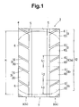
- Fig.1 is a developed plan view of a tire showing a design cycle.
- Fig.2A shows another example of the design cycle.
- Fig.2B shows still another example of the design cycle.
- Fig.3 shows a pitch sequence
- Fig.4 shows another example of the pitch sequence.
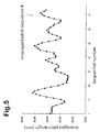
- Fig.5 shows an averaged-pitch sequence of the pitch sequence shown in Fig.3.
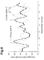
- Fig.6 shows a combination of the two identical averaged-pitch sequences shown in Fig.5.
- Fig.7 is a crossover average sequence of the combination of Fig.6 showing a difference S.
- Fig.8 is a graph showing the difference S as a function of the phase shift given in combining the averaged-pitch sequences.
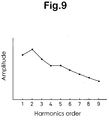
- Fig.9 is a graph showing the amplitude of harmonics of a waveform of a crossover average sequence such as shown in Fig.7.
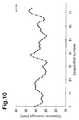
- Fig.10 shows a crossover average sequence of a test tire Ex.2.
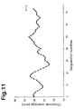
- Fig.11 shows a pitch sequence of the other region of a test tire Ex.4
- Fig.12 shows a crossover average sequence of the test tire Ex.4.
- the present invention can be applied to various tires having a tread pattern as far as axially different circumferential regions of the tread have cyclic patterns respectively.
- the cyclic patterns can be identical or different or symmetrical or asymmetrical, namely, every combination is possible.
- the cyclic patterns and non-cyclic pattern if any constitute the tread pattern.
- a central region 7 is provided with a non-cyclic pattern (rib) and each lateral region 9 is provided with a cyclic pattern (blocks), and a block-rib tread pattern is formed.
- the tread portion is axially divided into at least two circumferentially extending regions 9 having the same or almost same axial width.
- the number (P) of the regions 9 is usually two or three, and may be at most five.
- the circumferential regions 9 are each provided with a cyclic pattern by repeating a design cycle 3 in the circumferential direction while changing the circumferential pitch length thereof.
- the cyclic pattern is a part of the tread pattern formed by tread grooves
- the design cycle 3 is a minimum unit repeating in the tire circumferential direction. It is preferable that all the circumferential regions 9 have the same or almost same ground contacting area.
- the ground contacting area is the total in the circumference of the tire.
- the number (J) of the different pitch lengths in each circumferential region 9 is at least three, preferably, at most ten, namely the number (J) is in a range of from 3 to 10, more preferably 3 to 7, still more preferably 3 to 5.
- the total number (I) of the design cycles 3 (or the number of repetition) in each circumferential region 9 is set in a range of not less than 45, preferably not less than 50, more preferably not less than 60, but preferably at most about 120.
- each circumferential region 9 is regarded as a circumferential row of design cycles 3 i (i is a suffix number from 1 to I) having a number (J) of different pitch lengths L j (j is a suffix number from 1 to J).
- the sequence of the pitch lengths L j in each circumferential region 9 may be determined according to various methods. It is however, preferable that the ratio (L j /L 1 ) of the longest pitch length L j to the shortest pitch length L 1 is set in a range of from 1.20 to 1.70 in view of uneven wear and uniformity.
- Fig.3 shows an example of the pitch sequence, wherein the pitch length varies cyclically and gradually between a minimum and a maximum. (hereinafter, the "periodic arrangement")
- Fig.4 shows another example of the pitch sequence, wherein, in contrast with the above-mentioned periodic arrangement, the pitch length varies aperiodically.
- aperiodic arrangement This aperiodic arrangement (A) will be seen as random at first glance.
- Such aperiodic arrangement may be generated by a computer using a random-number-generating function or a chaos function based on the input data on the number (J) of the different pitch lengths L, the total number (I) of the design cycles 3 and the like.
- a predetermined number (n) of subsequent design cycles 3 i to 3 i+n are defined in one circumferential direction, and the average of the pitch lengths of the subsequent design cycles 3 i to 3 i+n (hereinafter, the "averaged pitch length") is found.
- the suffix number returns to the start if reached to the end.
- a sequence of the averaged pitch lengths (hereinafter, the "averaged-pitch sequence") whose number is equal to the total number (I) of the design cycles 3 is formed per each of the pitch sequences.
- a waveform of the envelope of the pitch sequence (A) is different from a waveform of the envelope of the averaged-pitch sequence (B) although the sequence (B) originates from the sequence (A).
- phase shift a combination of the averaged-pitch sequences of the circumferential regions 9 wherein the averaged-pitch sequences are not shifted and combinations wherein the averaged-pitch sequences are shifted relatively to one another in the circumferential direction of the tire are defined as many as possible by changing the amount of shift (hereinafter the "phase shift").
- each combination is provided with a phase shift in combining the averaged-pitch sequences.
- the phase shift is a comprehensive term. when the number of the combined averaged-pitch sequences is two, the phase shift means the only one phase shift therebetween. If the number is three or more, it means two or more phase shifts between them.
- Fig.6 shows a combination (C) of two identical averaged-pitch sequences (B) between which a phase shift ⁇ is given.
- the average of the averaged pitch lengths of the circumferential regions 9 (hereinafter the "crossover average") is found at each of a plurality circumferential positions, whereby a sequence of the crossover averages is formed per each of the combinations.
- the circumferential positions at which the crossover average is found or calculated are ideally equiangular positions around the tire axis.
- the equiangular positions can be determined independently from the total number (I) of the design cycles. In practice, however, as the variation of the pitch lengths is not so large, the sequential number of the design cycles is used as a pointer indicating the circumferential position or the distance from a given point.
- Fig.7 the crossover averages of the above-mentioned combination (c) are plotted sequentially (hereinafter the "crossover average sequence").
- the envelope thereof again describes a waveform different of the above-mentioned two waveforms.
- Each of the crossover average sequences may have a maximum crossover average and a minimum crossover average and accordingly, there is a certain difference S between the maximum and minimum.
- a sequence of which difference S is minimum or under a predetermined level is found.
- a flatter waveform is found.
- a higher harmonic such as 2nd or 4th harmonic instead of the waveform as it is in finding a flatter waveform or a minimum or smaller difference S.
- such a higher harmonic can be obtained by utilizing a well known Fourier expansion of the waveform.
- the sequence (or waveform) which is so found out has a specific phase shift which was given between the averaged-pitch sequences in combining them. of course, there is a possibility that the phase shift is zero.
- the above-mentioned cyclic patterns of the circumferential regions 9 are rearranged by giving the found-out phase shift between them.
- a tread portion 2 of a pneumatic tire 1 of size 225/60R16 for passenger cars is shown together with an exemplary ground contacting patch by a two-dot chain line.
- the tread portion 2 is provided with two circumferential grooves 5 extending circumferentially of the tire and axial grooves 6 extending from the circumferential grooves 5 to the tread edge (e).
- the central circumferential region 7 between the two circumferential grooves 5 is formed as a circumferentially continuously extending rib 7, and a cyclic pattern is not provided.
- the two lateral circumferential regions 9 axially outside the circumferential grooves 5 are each formed as a row 4 of blocks 10. In this example, the method is applied to the two lateral regions 9.
- a design cycle 3 may be made up of a complete block 10 and an adjacent axial groove 6.
- the borders between design cycles 3 lie along the axial groove edges on the same side. It is however, not always necessary that the borders are on the axial groove edges.
- the borders may be on the top faces of the blocks for example.
- a design cycle 3 may be made up of one of the rug grooves 20 and one of portions 21 therebetween which adjoins the rug groove 20.
- a design cycle 3 may be defined as a circumferential part corresponding to one cycle of the zigzag.
- an arrangement of design cycles 3a, 3b, 3c, 3d, 3e having different pitch lengths L 1 , L 2 , L 3 , L 4 , L 5 (short to long order) is defined.
- a sequence of the pitch lengths L 1 - L 5 is determined.
- the ratio (L 5 /L 1 ) of the longest pitch length L 5 to the shortest pitch length L 1 is set in a range of from 1.20 to 1.70.
- both of the circumferential width of the axial groove 6 and the circumferential length of the block 10 increase as the pitch length L increases.
- the pitch lengths of an existing cyclic pattern there is a possibility that the pitch length varies depending on the axial position if for example the inclination of the axial groove 6 is changed between the circumferentially adjacent axially grooves 6.
- the pitch lengths are defined at a definite axial position such as the axial edge or end (in this example, at the tread edge e), it may be enough for achieving the advantageous results.
- the determination of the pitch lengths of an existing cyclic pattern is not essential for the present invention.
- the two lateral regions 9 are provided with identical pitch sequences (A) although the cyclic patterns are mirror symmetry about the tire equator. But, it is also possible to use different pitch sequences.
- the total number (I) of the design cycles 3 is 74.
- the pitch sequence (A) is as follows.
- an averaged-pitch sequence (B) is defined with respect to only the pitch sequence (A).
- the average (Lx+Ly)/2 of the pitch lengths Lx and Ly of five subsequent design cycles 3 i to 3 i+5 is calculated to define an averaged-pitch sequence.
- combinations of the two averaged-pitch sequences (B) and (B) are defined by changing the phase shift ⁇ between them.
- the phase shift change is made at the step of the sequential number, and as a result, seventy-four combinations was defined.
- Fig.6 shows one of the combinations (C) provided with a phase shift ⁇ which is 39 (39 design cycles).
- the average (crossover average) of the averaged-pitches of the same order or the same sequential number in the combined averaged-pitch sequences is found over the sequential number, whereby a sequence (D) of the crossover averages is formed.
- the number of the sequences (D) is equal to that of the combinations, and the number of the crossover averages in each sequence (D) is the same as the total number (I).
- Fig.7 shows one of the crossover average sequences (D) which is of the above-mentioned combination (C) shown in Fig.6.
- this crossover average sequences (D) namely, in the combination (C)
- the difference S between the maximum crossover average and the minimum crossover average is about 10.6 mm. with respect to each combination, the difference S is found.
- the inventor also discovered that, by selecting a phase shift by which the difference S becomes less than 90 % of the maximum difference S (preferably less than 80 %, more preferably less than 65 %), the circumferential distribution of the tread pattern rigidity can be effectively uniformed. Thus, such a phase shift is also selectable.
- the tread pattern is designed and a tire vulcanizing mold is made, and using the mold, a pneumatic tire is molded.
- the tangential force variation TFV in 1st to 4th harmonics order was measured at a speed of 120 km/hr.
- the results are indicated by an index based on Ref. tire being 100, wherein the smaller the index number, the better the tire uniformity.
- a 3000 cc Japanese passenger car provided on all the wheels with test tires was coasted on a smooth asphalt road at a speed of 60 km/hr, and the noise in the car was evaluated into five ranks by the test driver, wherein the larger the rank number, the better the noise performance.
- the axial grooves 6 in the shoulder regions 9 were measured for the difference between the maximum groove depth and minimum groove depth.
- the difference is indicated by an index based on Ref. tire being 100, wherein the smaller the index number, the higher the uneven resistance.
Landscapes
- Engineering & Computer Science (AREA)
- Mechanical Engineering (AREA)
- Tires In General (AREA)
Abstract
Description
Although this method is effective in reducing a tire noise, it is not always effective in improving other performance of the tire such as vibration during high speed running, tire uniformity and the like. For example, there is a possibility that the tangential force variation TFV, radial force variation RFV and the like become rather worse in view of vibration during high speed running. when the periodicity of such a force variation is synchronized with the natural vibration of the suspensions, spring members or the like of the car at a certain running speed, even if the amplitude thereof is small, a vibration which can be felt is caused. Such a phenomenon is liable to occur at higher harmonics such as 2nd and 4th harmonics of the tangential force variation.
The pitch lengths L1-L5 are as follows.
| Design cycle | | mm | |
| 3a | L1 | 21.54 | |
| 3b | L2 | 23.12 | |
| 3c | L3 | 28.7 | |
| 3d | L4 | 32.28 | |
| 3e | L5 | 35.89 | |
| L5/L1 = 1.67 |
The pitch sequence (A) is as follows.
| 1 | 32.28 | 21 | 32.28 | 41 | 32.28 | 61 | 32.28 |
| 2 | 32.28 | 22 | 28.7 | 42 | 28.7 | 62 | 28.7 |
| 3 | 28.7 | 23 | 23.12 | 43 | 28.7 | 63 | 23.12 |
| 4 | 28.7 | 24 | 23.12 | 44 | 21.54 | 64 | 32.28 |
| 5 | 23.12 | 25 | 21.54 | 45 | 23.12 | 65 | 32.28 |
| 6 | 28.7 | 26 | 23.12 | 46 | 32.28 | 66 | 28.7 |
| 7 | 32.28 | 27 | 21.54 | 47 | 32.28 | 67 | 23.12 |
| 8 | 28.7 | 28 | 23.12 | 48 | 28.7 | 68 | 21.54 |
| 9 | 28.7 | 29 | 21.54 | 49 | 35.89 | 69 | 23.12 |
| 10 | 21.54 | 30 | 21.54 | 50 | 35.89 | 70 | 28.7 |
| 11 | 21.54 | 31 | 21.54 | 51 | 35.89 | 71 | 28.7 |
| 12 | 21.54 | 32 | 23.12 | 52 | 35.89 | 72 | 35.89 |
| 13 | 23.12 | 33 | 28.7 | 53 | 32.28 | 73 | 32.28 |
| 14 | 28.7 | 34 | 28.7 | 54 | 28.7 | 74 | 32.28 |
| 15 | 28.7 | 35 | 32.28 | 55 | 28.7 | ||
| 16 | 35.89 | 36 | 23.12 | 56 | 23.12 | ||
| 17 | 35.89 | 37 | 21.54 | 57 | 21.54 | ||
| 18 | 35.89 | 38 | 23.12 | 58 | 23.12 | ||
| 19 | 35.89 | 39 | 28.7 | 59 | 28.7 | ||
| 20 | 35.89 | 40 | 35.89 | 60 | 35.89 |
The following is the averaged-pitch sequence (B) of the above-mentioned pitch sequence (A).
| 1 | 29.02 | 21 | 25.75 | 41 | 26.87 | 61 | 29.73 |
| 2 | 28.3 | 22 | 23.92 | 42 | 26.87 | 62 | 29.02 |
| 3 | 28.3 | 23 | 22.49 | 43 | 27.58 | 63 | 27.9 |
| 4 | 28.3 | 24 | 22.49 | 44 | 27.58 | 64 | 27.58 |
| 5 | 28.3 | 25 | 22.17 | 45 | 30.45 | 65 | 25.75 |
| 6 | 27.98 | 26 | 22.17 | 46 | 33.01 | 66 | 25.04 |
| 7 | 26.55 | 27 | 21.86 | 47 | 33.73 | 67 | 25.04 |
| 8 | 24.4 | 28 | 22.17 | 48 | 34.45 | 68 | 27.59 |
| 9 | 23.29 | 29 | 23.29 | 49 | 35.17 | 69 | 29.74 |
| 10 | 23.29 | 30 | 24.72 | 50 | 33.73 | 70 | 31.57 |
| 11 | 24.72 | 31 | 26.87 | 51 | 32.29 | 71 | 32.29 |
| 12 | 27.59 | 32 | 27.18 | 52 | 29.74 | 72 | 33 |
| 13 | 30.46 | 33 | 26.87 | 53 | 26.87 | 73 | 31.56 |
| 14 | 33.01 | 34 | 25.75 | 54 | 25.04 | 74 | 30.85 |
| 15 | 34.45 | 35 | 25.75 | 55 | 25.04 | ||
| 16 | 35.89 | 36 | 26.47 | 56 | 26.47 | ||
| 17 | 35.17 | 37 | 28.31 | 57 | 28.31 | ||
| 18 | 33.73 | 38 | 29.74 | 58 | 29.74 | ||
| 19 | 31.18 | 39 | 30.85 | 59 | 29.74 | ||
| 20 | 28.62 | 40 | 29.42 | 60 | 30.45 |
| Tire | Ref. | Ex.1 | Ex.2 | Ex.3 | Ex.4 | |
| Pitch sequence | Table 1 | Table 1 | Table 1 | Table 1 | Table 1 | |
| Table 1 | Table 1 | Table 1 | Table 1 | Table 4 | ||
| Averaged-pitch sequence | Table 2 | Table 2 | Table 2 | Table 2 | Table 2 | |
| Table 2 | Table 2 | Table 2 | Table 2 | Table 5 | ||
| Phase shift | 0 | 39 | 24 | 5 | 10 | |
| Crossover average sequence | - | Fig.7 | Fig.10 | Fig.11 | Fig.12 | |
| Difference S (mm) | 14 | 10.6 | 8.1 | 10.3 | 7.4 | |
| TFV (index) Harmonic order | 1st | 100 | 70 | 80 | 90 | 65 |
| 2nd | 100 | 35 | 50 | 70 | 60 | |
| 3th | 100 | 60 | 120 | 100 | 40 | |
| 4th | 100 | 120 | 90 | 110 | 110 | |
| Noise | 3 | 3.5 | 3.4 | 3.2 | 3.5 | |
| Uneven wear | 100 | 92 | 95 | 96 | 90 |
| 1 | 28.7 | 21 | 23.12 | 41 | 28.7 | 61 | 23.12 |
| 2 | 28.7 | 22 | 23.12 | 42 | 21.54 | 62 | 32.28 |
| 3 | 23.12 | 23 | 21.54 | 43 | 23.12 | 63 | 32.28 |
| 4 | 28.7 | 24 | 23.12 | 44 | 32.28 | 64 | 28.7 |
| 5 | 32.28 | 25 | 21.54 | 45 | 32.28 | 65 | 23.12 |
| 6 | 28.7 | 26 | 23.12 | 46 | 28.7 | 66 | 21.54 |
| 7 | 28.7 | 27 | 21.54 | 47 | 35.89 | 67 | 23.12 |
| 8 | 21.54 | 28 | 21.54 | 48 | 35.89 | 68 | 28.7 |
| 9 | 21.54 | 29 | 21.54 | 49 | 35.89 | 69 | 28.7 |
| 10 | 21.54 | 30 | 23.12 | 50 | 35.89 | 70 | 35.89 |
| 11 | 23.12 | 31 | 28.7 | 51 | 32.28 | 71 | 32.28 |
| 12 | 28.7 | 32 | 28.7 | 52 | 28.7 | 72 | 32.28 |
| 13 | 28.7 | 33 | 32.28 | 53 | 28.7 | 73 | 32.28 |
| 14 | 35.89 | 34 | 23.12 | 54 | 23.12 | 74 | 32.28 |
| 15 | 35.89 | 35 | 21.54 | 55 | 21.54 | ||
| 16 | 35.89 | 36 | 23.12 | 56 | 23.12 | ||
| 17 | 35.89 | 37 | 28.7 | 57 | 28.7 | ||
| 18 | 35.89 | 38 | 35.89 | 58 | 35.89 | ||
| 19 | 32.28 | 39 | 32.28 | 59 | 32.28 | ||
| 20 | 28.7 | 40 | 28.7 | 60 | 28.7 |
| 1 | 28.3 | 21 | 22.49 | 41 | 27.58 | 61 | 27.9 |
| 2 | 28.3 | 22 | 22.49 | 42 | 27.58 | 62 | 27.58 |
| 3 | 28.3 | 23 | 22.17 | 43 | 30.45 | 63 | 25.75 |
| 4 | 27.98 | 24 | 22.17 | 44 | 33.01 | 64 | 25.04 |
| 5 | 26.55 | 25 | 21.86 | 45 | 33.73 | 65 | 25.04 |
| 6 | 24.4 | 26 | 22.17 | 46 | 34.45 | 66 | 27.54 |
| 7 | 23.29 | 27 | 23.29 | 47 | 35.17 | 67 | 29.74 |
| 8 | 23.29 | 28 | 24.72 | 48 | 33.73 | 68 | 31.57 |
| 9 | 24.72 | 29 | 26.87 | 49 | 32.29 | 69 | 32.29 |
| 10 | 27.59 | 30 | 27.18 | 50 | 29.74 | 70 | 33 |
| 11 | 30.46 | 31 | 26.87 | 51 | 26.87 | 71 | 31.56 |
| 12 | 33.01 | 32 | 25.75 | 52 | 25.04 | 72 | 30.85 |
| 13 | 34.45 | 33 | 35.75 | 53 | 25.04 | 73 | 29.02 |
| 14 | 35.89 | 34 | 24.47 | 54 | 26.47 | 74 | 28.3 |
| 15 | 35.17 | 35 | 26.31 | 55 | 28.31 | ||
| 16 | 33.73 | 36 | 27.74 | 56 | 29.74 | ||
| 17 | 31.18 | 37 | 28.85 | 57 | 29.74 | ||
| 18 | 28.62 | 38 | 27.42 | 58 | 30.45 | ||
| 19 | 25.75 | 39 | 26.87 | 59 | 29.73 | ||
| 20 | 23.92 | 40 | 26.87 | 60 | 29.02 |
Claims (17)
- In a method of arranging cyclic patterns in a tire tread, the tire tread comprising a number (P) of circumferential regions each provided with a cyclic pattern formed by circumferentially repeating a number (I) of design cycles having a number (J) of different pitch lengths, the pitch lengths of the design cycles in each said circumferential region arranged circumferentially of the tire in a sequence whereby the number (P) of sequences of the pitch lengths are defined, the improvement comprising:obtaining, with respect to each of the design cycles, an averaged pitch of the pitch lengths of a number (n) of circumferentially subsequent design cycles to define a sequence of averaged pitches per each of the circumferential regions, whereby the number (P) of sequences of the averaged pitches are defined;defining a number (Q) of combinations of the number (P) of the sequences of averaged pitches by changing phase between the sequences;obtaining, with respect to the averaged pitches of the number (P) of the combined sequences in each of the combinations, a crossover average of averaged pitches, whereby a series of the crossover averages is defined per each of the combination;obtaining, from said a series of the crossover averages, a difference between a maximum and a minimum of the crossover averages or alternatively between a maximum and a minimum of the amplitude of a harmonic of said a series of the crossover averages, with respect to each of the combinations;finding, from the differences of the combinations, a combination having a smaller difference to determine the phase shift given to the sequences of averaged pitches in making the combination; andrearranging the cyclic patterns of the circumferential regions in accordance with the found phase shift.
- The method according to claim 1, which comprises
determining the number (n) of the circumferentially subsequent design cycles such that the total circumferential length of the subsequent design cycles is substantially equal to the ground contacting length of the tire tread. - The method according to claim 1, wherein
the number (n) of the circumferentially subsequent design cycles is in a range of from 3 to 7. - The method according to claim 1, wherein
said difference is a difference between a maximum and a minimum of the amplitude of the harmonic, and the harmonic is the fundamental harmonic. - The method according to claim 1, wherein
said difference is a difference between a maximum and a minimum of the amplitude of the harmonic, and the harmonic is a higher harmonic such as second harmonic, third harmonic and forth harmonic. - The method according to claim 1, wherein
said finding of a combination having a smaller difference comprises
finding a maximum difference from said differences of the combinations,
determining a standard difference based on the maximum difference, and
selecting combinations having a difference under the standard difference. - The method according to claim 6, wherein
the standard difference is 90 % of the maximum difference. - The method according to claim 6, wherein
the standard difference is 80 % of the maximum difference. - The method according to claim 6, wherein
the standard difference is 65 % of the maximum difference. - The method according to claim 1, wherein
all the pitch lengths' sequences of the circumferential regions are identical. - The method according to claim 1, wherein
all the pitch lengths' sequences of the circumferential regions are different from one another. - The method according to claim 1, wherein
at least one of the pitch lengths' sequences of the circumferential regions is different from the rest. - The method according to claim 10 or 11, wherein
the number (P) of circumferential regions is two. - The method according to claim 1, wherein
at least one of the pitch lengths' sequences of the circumferential regions has a periodic pitch length variation. - The method according to claim 1, wherein
at least one of the pitch lengths' sequences of the circumferential regions has an irregular pitch length variation. - The method according to claim 1, wherein
the circumferential regions have the substantially same axial width - A pneumatic tire comprising a tread comprising circumferential regions provided with cyclic patterns arranged according to any of claims 1-17.
Applications Claiming Priority (2)
| Application Number | Priority Date | Filing Date | Title |
|---|---|---|---|
| JP2001093515 | 2001-03-28 | ||
| JP2001093515A JP3566939B2 (en) | 2001-03-28 | 2001-03-28 | Unit pattern arrangement method for pneumatic tires |
Publications (3)
| Publication Number | Publication Date |
|---|---|
| EP1245410A2 true EP1245410A2 (en) | 2002-10-02 |
| EP1245410A3 EP1245410A3 (en) | 2003-05-28 |
| EP1245410B1 EP1245410B1 (en) | 2006-06-28 |
Family
ID=18947845
Family Applications (1)
| Application Number | Title | Priority Date | Filing Date |
|---|---|---|---|
| EP02006936A Expired - Lifetime EP1245410B1 (en) | 2001-03-28 | 2002-03-26 | Method for arranging cyclic patterns in tire tread |
Country Status (4)
| Country | Link |
|---|---|
| US (1) | US6800161B2 (en) |
| EP (1) | EP1245410B1 (en) |
| JP (1) | JP3566939B2 (en) |
| DE (1) | DE60212749T2 (en) |
Cited By (2)
| Publication number | Priority date | Publication date | Assignee | Title |
|---|---|---|---|---|
| EP1920949A1 (en) * | 2006-11-10 | 2008-05-14 | The Goodyear Tire & Rubber Company | Reduced noise pneumatic tire |
| CN101920635A (en) * | 2009-06-12 | 2010-12-22 | 住友橡胶工业株式会社 | Air-inflation tyre and manufacture method thereof |
Families Citing this family (39)
| Publication number | Priority date | Publication date | Assignee | Title |
|---|---|---|---|---|
| AU2002335655A1 (en) * | 2001-08-22 | 2003-03-10 | Bridgestone/Firestone North American Tire, Llc | Method of analyzing tire pitch sequence based on lug stiffness variations |
| CN1313289C (en) * | 2002-01-31 | 2007-05-02 | 米其林技术公司 | Tire tread design and the construction method thereof |
| US7181891B2 (en) * | 2003-09-08 | 2007-02-27 | Quiet Solution, Inc. | Acoustical sound proofing material and methods for manufacturing same |
| US7700086B2 (en) * | 2003-11-06 | 2010-04-20 | Pluromed, Inc. | Internal clamp for surgical procedures |
| US8495851B2 (en) | 2004-09-10 | 2013-07-30 | Serious Energy, Inc. | Acoustical sound proofing material and methods for manufacturing same |
| US7921965B1 (en) | 2004-10-27 | 2011-04-12 | Serious Materials, Inc. | Soundproof assembly and methods for manufacturing same |
| US7909136B2 (en) * | 2004-11-24 | 2011-03-22 | Serious Materials, Inc. | Soundproof assembly |
| US7798287B1 (en) | 2005-01-20 | 2010-09-21 | Serious Materials, Inc. | Acoustical ceiling panels |
| US8029881B2 (en) | 2005-11-04 | 2011-10-04 | Serious Energy, Inc. | Radio frequency wave reducing material and methods for manufacturing same |
| US20070175565A1 (en) * | 2006-01-27 | 2007-08-02 | Brown Jack E Jr | Continuous variable pitching methods |
| US20080093010A1 (en) * | 2006-10-17 | 2008-04-24 | Bridgestone Firestone North America Tire, Llc | Method for designing the fundamental pitch for a tire tread pattern with variable lug count by rib |
| US7987645B2 (en) * | 2007-03-29 | 2011-08-02 | Serious Materials, Inc. | Noise isolating underlayment |
| US9388568B2 (en) | 2007-04-06 | 2016-07-12 | Pacific Coast Building Products, Inc. | Acoustical sound proofing material with improved fracture characteristics and methods for manufacturing same |
| US7883763B2 (en) | 2007-04-12 | 2011-02-08 | Serious Materials, Inc. | Acoustical sound proofing material with controlled water-vapor permeability and methods for manufacturing same |
| US8424251B2 (en) | 2007-04-12 | 2013-04-23 | Serious Energy, Inc. | Sound Proofing material with improved damping and structural integrity |
| US8397864B2 (en) | 2007-04-24 | 2013-03-19 | Serious Energy, Inc. | Acoustical sound proofing material with improved fire resistance and methods for manufacturing same |
| US8181738B2 (en) | 2007-04-24 | 2012-05-22 | Serious Energy, Inc. | Acoustical sound proofing material with improved damping at select frequencies and methods for manufacturing same |
| US10174499B1 (en) | 2007-05-01 | 2019-01-08 | Pacific Coast Building Products, Inc. | Acoustical sound proofing material for architectural retrofit applications and methods for manufacturing same |
| US20080286609A1 (en) * | 2007-05-15 | 2008-11-20 | Surace Kevin J | Low embodied energy wallboards and methods of making same |
| US20090000245A1 (en) * | 2007-06-28 | 2009-01-01 | Tinianov Brandon D | Methods of manufacturing acoustical sound proofing material |
| US7908818B2 (en) * | 2008-05-08 | 2011-03-22 | Serious Materials, Inc. | Methods of manufacturing acoustical sound proofing materials with optimized fracture characteristics |
| US9387649B2 (en) | 2007-06-28 | 2016-07-12 | Pacific Coast Building Products, Inc. | Methods of manufacturing acoustical sound proofing materials with optimized fracture characteristics |
| US7914914B2 (en) | 2007-06-30 | 2011-03-29 | Serious Materials, Inc. | Low embodied energy sheathing panels with optimal water vapor permeance and methods of making same |
| US7799410B2 (en) * | 2007-06-30 | 2010-09-21 | Serious Materials, Inc. | Acoustical sound proofing material with improved damping at select frequencies and methods for manufacturing same |
| US8337993B2 (en) | 2007-11-16 | 2012-12-25 | Serious Energy, Inc. | Low embodied energy wallboards and methods of making same |
| USD630997S1 (en) | 2010-08-26 | 2011-01-18 | Bridgestone Americas Tire Operations, Llc | Tire tread |
| US8718990B2 (en) * | 2010-12-23 | 2014-05-06 | The Goodyear Tire & Rubber Company | Tire second order harmonics with rib shift methodology |
| FR2969956B1 (en) * | 2010-12-30 | 2013-02-08 | Michelin Soc Tech | VULCANIZATION MOLD FOR VULCANIZING AND MOLDING A TIRE |
| JP5868303B2 (en) * | 2012-10-16 | 2016-02-24 | 横浜ゴム株式会社 | Pneumatic tire |
| JP6476565B2 (en) * | 2013-09-30 | 2019-03-06 | 横浜ゴム株式会社 | Pitch array determination method, pitch array determination device, pitch array determination program |
| EP3234915A2 (en) * | 2014-12-19 | 2017-10-25 | Compagnie Générale des Etablissements Michelin | Method for detecting stipes in a tyre |
| CA2988547C (en) | 2016-12-15 | 2021-01-26 | Certainteed Gypsum, Inc. | Plaster boards and methods for making them |
| ES2965484T3 (en) | 2017-09-26 | 2024-04-15 | Certainteed Gypsum Inc | Plasterboards having internal layers and methods of making them |
| EP3688246A4 (en) | 2017-09-28 | 2021-05-19 | CertainTeed Gypsum, Inc. | PLASTERBOARD AND METHOD OF MANUFACTURING THEREOF |
| DK3688245T3 (en) | 2017-09-30 | 2023-06-19 | Certainteed Gypsum Inc | Tapered plasterboards and methods of making them |
| JP7497585B2 (en) * | 2020-03-19 | 2024-06-11 | 住友ゴム工業株式会社 | Tire, method for determining arrangement of tire pattern units, method for determining division position of tread segments, tire design method, and tire manufacturing method |
| JP7497584B2 (en) * | 2020-03-19 | 2024-06-11 | 住友ゴム工業株式会社 | Tire, tire manufacturing method, tire design method, and method for determining arrangement of pattern constituent units |
| JP7497583B2 (en) * | 2020-03-19 | 2024-06-11 | 住友ゴム工業株式会社 | Tire, tire manufacturing method, tire design method, and method for determining arrangement of pattern constituent units |
| JP7694270B2 (en) * | 2021-09-02 | 2025-06-18 | 住友ゴム工業株式会社 | tire |
Family Cites Families (3)
| Publication number | Priority date | Publication date | Assignee | Title |
|---|---|---|---|---|
| US5309965A (en) * | 1991-08-20 | 1994-05-10 | General Tire, Inc. | Multiple pitch sequence optimization |
| DE4332811C2 (en) * | 1993-09-27 | 1996-12-05 | Continental Ag | Profiled vehicle tires and method for measuring the optimal phase offset between adjacent tread parts |
| US5865921A (en) * | 1996-02-26 | 1999-02-02 | Bridgestone/Firestone, Inc. | Tire noise treatment |
-
2001
- 2001-03-28 JP JP2001093515A patent/JP3566939B2/en not_active Expired - Fee Related
-
2002
- 2002-03-26 EP EP02006936A patent/EP1245410B1/en not_active Expired - Lifetime
- 2002-03-26 DE DE60212749T patent/DE60212749T2/en not_active Expired - Lifetime
- 2002-03-28 US US10/107,362 patent/US6800161B2/en not_active Expired - Lifetime
Cited By (2)
| Publication number | Priority date | Publication date | Assignee | Title |
|---|---|---|---|---|
| EP1920949A1 (en) * | 2006-11-10 | 2008-05-14 | The Goodyear Tire & Rubber Company | Reduced noise pneumatic tire |
| CN101920635A (en) * | 2009-06-12 | 2010-12-22 | 住友橡胶工业株式会社 | Air-inflation tyre and manufacture method thereof |
Also Published As
| Publication number | Publication date |
|---|---|
| US6800161B2 (en) | 2004-10-05 |
| EP1245410A3 (en) | 2003-05-28 |
| JP3566939B2 (en) | 2004-09-15 |
| DE60212749T2 (en) | 2007-06-28 |
| DE60212749D1 (en) | 2006-08-10 |
| JP2002283811A (en) | 2002-10-03 |
| EP1245410B1 (en) | 2006-06-28 |
| US20030041949A1 (en) | 2003-03-06 |
Similar Documents
| Publication | Publication Date | Title |
|---|---|---|
| US6800161B2 (en) | Method of arranging cyclic patterns in tire tread | |
| EP0542493B1 (en) | Tire pitch sequencing for reduced tire tread noise | |
| KR970000519B1 (en) | Optimization of Multiple Pitch Sequences | |
| EP0618090B1 (en) | Tyres | |
| US5769990A (en) | Method of making tire with tire tread pitch bands | |
| US6363984B1 (en) | Tire tread pitch sequencing for reduced noise | |
| US5974872A (en) | Pitch arrangement evaluation system of tread pattern of pneumatic tire | |
| RU2524522C2 (en) | Pneumatic tire | |
| JP3325296B2 (en) | Method of forming tread pattern | |
| JPH05169915A (en) | Pneumatic tire | |
| CA1050869A (en) | Noise reduction in pneumatic tires | |
| JP4287520B2 (en) | Pneumatic tire | |
| EP3330105B1 (en) | Tire | |
| EP0752326B1 (en) | Pneumatic tyre | |
| RU2777546C1 (en) | Studded tyre for vehicle wheels | |
| JPH03136908A (en) | Pneumatic tire with reduced noise characteristics | |
| JPH04108004A (en) | Pneumatic tire | |
| JPH08276707A (en) | Pneumatic tire | |
| JP2022038461A (en) | Tire, tire pattern constitutional unit arrangement determination method, tread segment split position determination method, and tire design method | |
| JP2000085317A (en) | Pneumatic tire | |
| JP2000233607A (en) | Pneumatic radial tire | |
| JPH0825907A (en) | Emergency use tire | |
| JPH06297915A (en) | Pneumatic tire | |
| KR20010088681A (en) | Pitch Array Determination Method of Tire | |
| JPH11192816A (en) | Pneumatic tire |
Legal Events
| Date | Code | Title | Description |
|---|---|---|---|
| PUAI | Public reference made under article 153(3) epc to a published international application that has entered the european phase |
Free format text: ORIGINAL CODE: 0009012 |
|
| AK | Designated contracting states |
Kind code of ref document: A2 Designated state(s): AT BE CH CY DE DK ES FI FR GB GR IE IT LI LU MC NL PT SE TR |
|
| AX | Request for extension of the european patent |
Free format text: AL;LT;LV;MK;RO;SI |
|
| PUAL | Search report despatched |
Free format text: ORIGINAL CODE: 0009013 |
|
| AK | Designated contracting states |
Designated state(s): AT BE CH CY DE DK ES FI FR GB GR IE IT LI LU MC NL PT SE TR |
|
| AX | Request for extension of the european patent |
Extension state: AL LT LV MK RO SI |
|
| AKX | Designation fees paid | ||
| 17P | Request for examination filed |
Effective date: 20031023 |
|
| RBV | Designated contracting states (corrected) |
Designated state(s): DE FR GB |
|
| REG | Reference to a national code |
Ref country code: DE Ref legal event code: 8566 |
|
| 17Q | First examination report despatched |
Effective date: 20040420 |
|
| GRAP | Despatch of communication of intention to grant a patent |
Free format text: ORIGINAL CODE: EPIDOSNIGR1 |
|
| GRAS | Grant fee paid |
Free format text: ORIGINAL CODE: EPIDOSNIGR3 |
|
| GRAA | (expected) grant |
Free format text: ORIGINAL CODE: 0009210 |
|
| RIC1 | Information provided on ipc code assigned before grant |
Ipc: B60C 11/00 20060101AFI20060518BHEP |
|
| AK | Designated contracting states |
Kind code of ref document: B1 Designated state(s): DE FR GB |
|
| REG | Reference to a national code |
Ref country code: GB Ref legal event code: FG4D |
|
| REF | Corresponds to: |
Ref document number: 60212749 Country of ref document: DE Date of ref document: 20060810 Kind code of ref document: P |
|
| ET | Fr: translation filed | ||
| PLBE | No opposition filed within time limit |
Free format text: ORIGINAL CODE: 0009261 |
|
| STAA | Information on the status of an ep patent application or granted ep patent |
Free format text: STATUS: NO OPPOSITION FILED WITHIN TIME LIMIT |
|
| 26N | No opposition filed |
Effective date: 20070329 |
|
| PGFP | Annual fee paid to national office [announced via postgrant information from national office to epo] |
Ref country code: GB Payment date: 20080326 Year of fee payment: 7 |
|
| PGFP | Annual fee paid to national office [announced via postgrant information from national office to epo] |
Ref country code: FR Payment date: 20080311 Year of fee payment: 7 |
|
| GBPC | Gb: european patent ceased through non-payment of renewal fee |
Effective date: 20090326 |
|
| REG | Reference to a national code |
Ref country code: FR Ref legal event code: ST Effective date: 20091130 |
|
| PG25 | Lapsed in a contracting state [announced via postgrant information from national office to epo] |
Ref country code: GB Free format text: LAPSE BECAUSE OF NON-PAYMENT OF DUE FEES Effective date: 20090326 Ref country code: FR Free format text: LAPSE BECAUSE OF NON-PAYMENT OF DUE FEES Effective date: 20091123 |
|
| PGFP | Annual fee paid to national office [announced via postgrant information from national office to epo] |
Ref country code: DE Payment date: 20190312 Year of fee payment: 18 |
|
| REG | Reference to a national code |
Ref country code: DE Ref legal event code: R119 Ref document number: 60212749 Country of ref document: DE |
|
| PG25 | Lapsed in a contracting state [announced via postgrant information from national office to epo] |
Ref country code: DE Free format text: LAPSE BECAUSE OF NON-PAYMENT OF DUE FEES Effective date: 20201001 |