EP1245359A2 - Apparatus for molding honeycomb structure and molding method - Google Patents
Apparatus for molding honeycomb structure and molding method Download PDFInfo
- Publication number
- EP1245359A2 EP1245359A2 EP02005915A EP02005915A EP1245359A2 EP 1245359 A2 EP1245359 A2 EP 1245359A2 EP 02005915 A EP02005915 A EP 02005915A EP 02005915 A EP02005915 A EP 02005915A EP 1245359 A2 EP1245359 A2 EP 1245359A2
- Authority
- EP
- European Patent Office
- Prior art keywords
- spinneret
- honeycomb structure
- press plate
- molding
- gap
- Prior art date
- Legal status (The legal status is an assumption and is not a legal conclusion. Google has not performed a legal analysis and makes no representation as to the accuracy of the status listed.)
- Withdrawn
Links
Images








Classifications
-
- B—PERFORMING OPERATIONS; TRANSPORTING
- B28—WORKING CEMENT, CLAY, OR STONE
- B28B—SHAPING CLAY OR OTHER CERAMIC COMPOSITIONS; SHAPING SLAG; SHAPING MIXTURES CONTAINING CEMENTITIOUS MATERIAL, e.g. PLASTER
- B28B3/00—Producing shaped articles from the material by using presses; Presses specially adapted therefor
- B28B3/20—Producing shaped articles from the material by using presses; Presses specially adapted therefor wherein the material is extruded
- B28B3/26—Extrusion dies
- B28B3/269—For multi-channeled structures, e.g. honeycomb structures
-
- B—PERFORMING OPERATIONS; TRANSPORTING
- B28—WORKING CEMENT, CLAY, OR STONE
- B28B—SHAPING CLAY OR OTHER CERAMIC COMPOSITIONS; SHAPING SLAG; SHAPING MIXTURES CONTAINING CEMENTITIOUS MATERIAL, e.g. PLASTER
- B28B3/00—Producing shaped articles from the material by using presses; Presses specially adapted therefor
- B28B3/20—Producing shaped articles from the material by using presses; Presses specially adapted therefor wherein the material is extruded
- B28B3/26—Extrusion dies
- B28B3/2654—Means for heating or cooling the die
Definitions
- the present invention relates to an apparatus for molding a honeycomb structure and a method for molding a honeycomb structure using the molding apparatus. More particularly, it relates to a molding apparatus for making a honeycomb structure useful, for example, as a catalyst carrier for controlling exhaust gases of automobiles, and a method for molding the honeycomb structure which makes it possible to reduce failure in formation of outer walls of the honeycomb structure by adding various functions to a press plate which fixes a spinneret.
- honeycomb structures made of ceramics materials or metallic materials as shown in Figs. 6-8 are used as catalyst carriers for exhaust gas purification apparatuses of automobiles.
- Fig. 7 is an oblique view of a honeycomb structure 61
- Fig. 8 is a front view of the honeycomb structure 61
- Fig. 6 is a partially enlarged view of the honeycomb structure 61.
- This honeycomb structure is nearly columnar as shown in Fig. 7, and comprises partition walls 64 having a honeycomb structure which form many cells 63 and an outer wall 62 covering the outer periphery.
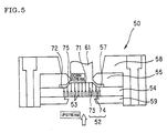
- FIG. 5 is a vertical sectional view of an apparatus 50 for molding honeycomb structure which is provided with back pore part 53 from which a molding material is introduced, a spinneret 54 having slit a part 52 which ejects the molding material, and a press plate 55 provided downstream the spinneret 54. Extrusion molding is carried out using this apparatus to make the honeycomb structure 61.
- the spinneret 54 comprises inner side part 71 and outer periphery part 72, and the inner side part 71 protrudes to downstream side to form a level difference part 75 between the inner side part 71 and the outer periphery part 72.
- the press plate At the press plate, there is provided a gap part 57 which molds the outer wall of the honeycomb structure.
- Press jig 58 and back press plate 59 are holders for setting the spinneret 54 and the press plate 55.
- the molding material is extruded from the upstream side of spinneret 54 to the downstream side through the spinneret 54 by an extruder (not shown) as shown in Fig. 5.
- the molding material extruded from slit 73 provided in the inner side part 71 of the spinneret 54 opened on the downstream side forms a honeycomb structure comprising many cells 63.
- the molding material extruded from slit 74 provided in the outer peripheral part 72 of the spinneret 54 changes in its running direction to the level difference part 75 from the extrusion direction with rupturing of the honeycomb shape being caused by the action of the slit part 57, and again changes in its running direction to the extrusion direction at the position where the press plate 55 opens, thereby forming an outer wall 62 surrounding the cells 63.
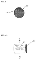
- Fig. 9 is a front view of a honeycomb structure having wavy wall
- Fig. 10 is a side view of a honeycomb structure having wavy wall. It is considered that wavy wall portion 92 of the honeycomb structure 91 is formed because the amount of the molding material becomes larger than in other portions and cells are ruptured to form waviness, and it is assumed that this is caused since molding speed of the outer wall part is higher than that of the part of the cells 63.
- honeycomb structure which is to be columnar is formed with undulation, resulting in increase of gas permeability resistance in addition to inferior appearance and thus the honeycomb structure is not suitable as product.
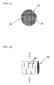
- Fig. 11 is a front view of a honeycomb structure having burrs
- Fig. 12 is a side view of a honeycomb structure having burrs. It is considered that the burr portions 96 of the honeycomb structure 95 are formed because the amount of the molding material becomes smaller than in other portions and the outer wall is not formed, and it is assumed that this is caused since molding speed of the outer wall portion 62 is lower than that of the portion of the cells 63.
- the molding speed of the portion of the outer wall 62 becomes higher or lower than that of the portion of the cells 63, since fluidity of the molding material cannot necessarily be maintained constant and there is variation in working precision of the spinneret or the press plate.
- the fluidity of the molding material is affected by various factors. For example, in the case of ceramics, the fluidity is affected by delicate variations of particle diameter or shape of the molding material, water content, kneading degree, atmospheric temperature and humidity, etc. Therefore, the fluidity of the molding material changes momentarily even in a day, and can hardly be maintained constant.
- JP-A-8-239701 discloses a metallic honeycomb body and a method for making the same.
- Fig. 2 is an elevation sectional view of a die assembly of the disclosed apparatus for making metallic honeycomb bodies.
- the apparatus 20 for making metallic honeycomb materials comprising combination of a mask 22 having a ring reservoir and a die 24 having a skin forming slit 28 of a suitable size, a plasticized batch material discharged outside from slots 23 near the peripheral part of the die 24 is discharged into adjacent but different two areas of the die 24.
- honeycomb cell portion
- outer skin outer wall portion
- JP-A-9-277234 discloses an apparatus for molding honeycomb structures and a molding method.
- Fig. 3 is a sectional view of the disclosed apparatus for molding honeycomb structures.
- the molding apparatus 30 for honeycomb structures comprises a metal mold 33 having a slit 31 for molding the honeycomb structure 32 and a guide ring 34, and the guide ring 34 has an opening edge part 35 and a pool part 36, and, besides, a temperature adjusting device 37 for adjusting the temperature of the guide ring 34.
- this temperature adjusting device 37 By this temperature adjusting device 37, temperature of ceramic material for forming outer skin (outer wall) which is retained in the pool part 36 of the guide ring 34, and, as a result, fluidity of the ceramic material can be changed and, hence, the molding rate of the outer skin (outer wall) and that of the body portion (cell portion) can be coincided. Thus, formation of wrinkles, burrs, etc. can be inhibited.
- the present invention has been made in view of the above problems, and the object is to provide a honeycomb structure molding apparatus capable of inhibiting failure in formation of outer wall by making possible the fine adjustment of molding rate of the outer wall of honeycomb structure or realizing to keep more constant the molding rate, and a molding method using the apparatus.
- honeycomb structure molding apparatuses there are provided three embodiments of honeycomb structure molding apparatuses and two different methods for molding the honeycomb structures.
- a first honeycomb structure molding apparatus having at least a spinneret provided with a back pore part for introducing a molding material and a slit part for extruding the molding material, and a press plate for fixing the spinneret, characterized in that the spinneret comprises an inner side part and an outer peripheral part, the inner side part is protruded to the downstream side to form a level difference part between the inner side part and the outer peripheral part, the press plate is opened opposing the inner side part of the spinneret and presses the downstream side of the outer peripheral part of the spinneret through a gap part formed between the spinneret and the press plate, and there is provided a gap adjusting means capable of changing width of the gap of the gap part.
- the first honeycomb structure molding apparatus of the present invention can be suitably used for molding a honeycomb structure where the molding material is a mixed molding material containing at least a ceramics powder and/or a metal powder and a molding aid.
- the gap adjusting means preferably comprises a flexible part provided at the press plate and an adjusting instrument bending the flexible part, said adjusting means bending the flexible part to fix it at a desired position and adjust the width of the gap.
- a screw which pierces through the press plate and whose head is exposed on the upper surface of the press plate can be used as the adjusting instrument.
- the gap adjusting means is provided at an inner peripheral end part of the press plate and opposite to the innermost part of the outer peripheral part of the spinneret, and a plurality of the gap adjusting means are provided dividing the inner periphery at equal intervals.
- the range of adjustment of the width of the gap by the gap adjusting means is preferably about 0-0.50 mm.
- a second honeycomb structure molding apparatus for obtaining a honeycomb structure by extrusion molding a molding material containing at least a ceramics powder and a molding aid, wherein at least a spinneret provided with a back pore part for introducing the molding material and a slit part for extruding the molding material, and a press plate for fixing the spinneret, the spinneret comprises an inner side part and an outer peripheral part, the inner side part is protruded to the downstream side to form a level difference part between the inner side part and the outer peripheral part, the press plate is opened opposite to the inner side part of the spinneret and press the downstream side of the outer peripheral part of the spinneret through a gap part, and a reservoir part comprising a ring dented part is provided in the press plate at the position outside by a given length L facing the gap part from the innermost end of the face opposing the downstream side of the outer periphery part of the spinneret.
- a spinneret provided with a back
- a third honeycomb structure molding apparatus having the characteristics of both the first honeycomb structure molding apparatus and the second honeycomb structure molding apparatus.
- the first to third honeycomb structure molding apparatuses are preferably provided with a temperature control means capable of changing the temperature of the molding material.
- the temperature control means is preferably a means having at least a hollow passage provided in the press plate and a water feeding device which allows a circulating water of a desired temperature to flow through the hollow passage, and controlling the temperature of the molding material by changing the temperature of the press plate.
- the range of the temperature to be controlled by the temperature control means is preferably 5-35°C.
- the temperature control means is provided with a temperature control meter at the press plate and/or the spinneret, whereby automatic temperature control becomes possible.
- the level difference part formed at the spinneret is tapered forming an inclined plane of about 30-60° or right-angled forming an inclined plane of about 90°.
- the first to third honeycomb structure molding apparatuses of the present invention can be suitably used for making a honeycomb structure used as catalyst carriers for purification of exhaust gas of automobiles in which a catalyst is supported on the surface of cell partition wall and/or the inner surface of pores in the partition wall.
- a first method for molding a honeycomb structure which comprises extrusion molding a molding material containing at least a ceramics powder and/or a metallic powder and a molding aid, characterized in that there is used a honeycomb structure molding apparatus having at least a spinneret provided with a back pore part for introducing a molding material and a slit part for extruding the molding material and a press plate for fixing the spinneret, the spinneret comprising an inner side part and an outer peripheral part, the inner side part being protruded to the downstream side to form a level difference part between the inner side part and the outer peripheral part, the press plate being opened opposite to the inner side part of the spinneret and pressing the downstream side of the outer peripheral part of the spinneret through a gap part formed between the spinneret and the press plate, and the molding material is extruded with adjusting the width of the gap of the gap part, thereby to form an outer wall having a uniform thickness.
- a second method for molding a honeycomb structure which comprises extrusion molding a molding material containing at least a ceramics powder and/or a metallic powder and a molding aid, characterized in that there is used a honeycomb structure molding apparatus having at least a spinneret provided with a back pore part for introducing a molding material and a slit part for extruding the molding material and a press plate for fixing the spinneret, the spinneret comprising an inner side part and an outer peripheral part, the inner side part being protruded to the downstream side to form a level difference part between the inner side part and the outer peripheral part, the press plate being opened opposite to the inner side part of the spinneret and pressing the downstream side of the outer peripheral part of the spinneret through a gap part formed between the spinneret and the press plate, a reservoir part comprising a ring dented part being provided in the press plate at the position outside by a given length L facing the gap part from the innermost end of the face opposing
- variation of thickness of the outer wall can be within about ⁇ 0.05 mm.
- honeycomb structure molding apparatus of the present invention will be specifically explained by the following embodiments, but these embodiments should never be construed as limiting the invention and various variations, modifications and improvements can be made without departing from the scope of the invention.
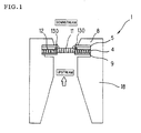
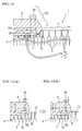
- Fig. 1 is a sectional view showing one example of the first honeycomb structure molding apparatus of the present invention
- Fig. 13 is a partially enlarged sectional view
- Fig. 14 (a) and (b) explain the operation
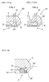
- Fig. 17 (a) and (b) are partially enlarged sectional views showing two examples of the gap adjusting means provided at the first honeycomb structure molding apparatus of the present invention.
- the first honeycomb structure molding apparatus 1 of the present invention is an apparatus for making a honeycomb structure using as a molding material, for example, one or both of a ceramics powder and a metallic powder which are mixed with a molding aid.
- the first honeycomb structure molding apparatus 1 has a spinneret 4 provided with a back pore part 3 for introduction of the molding material and a slit part 2 for extruding the molding material.
- the spinneret 4 comprises an inner side part 11 and an outer peripheral part 12, and is fixed by a back press plate 9 provided on the upstream side and a press plate 5 provided on the downstream side.
- Spinneret 4, press plate 5 and back press plate 9 are held by a press jig 8, and the press jig 8 is supported by a die holder 18.
- the inner side part 11 of the spinneret 4 is protruded to the downstream side to form a level difference part 15 between the inner side part 11 and the outer peripheral part 12.
- the slit part 2 provided at the spinneret 4 comprises slit 13 provided at the inner side part 11 and slit 14 provided at the outer peripheral part 12.
- the press plate 5 is opened at the portion of downstream side opposite to the inner side part 11, namely, nearly the central portion, and simultaneously presses the downstream side of the outer peripheral part 12 of the spinneret 4 spacing a gap part 7 formed between the spinneret 4 and the press plate 5, thereby fixing the spinneret 4.
- the gap part 7 is a part through which the molding material passes, and includes the gap formed between the level difference part of the spinneret and the press plate.
- the width of the gap part 7 means a distance between the spinneret 4 and the press plate 5 in the gap part 7 which face each other nearly in parallel.
- a gap adjusting means 130 capable of changing the width of the gap of the gap part 7 is provided at the press plate 5.
- the gap adjusting means 130 comprises a flexible part 132 and an adjusting instrument 131 which flexes the flexible part 132.
- position at which the flexible part 132 is formed or size of the flexible part 132 is not limited as far as the width of the gap of the gap part 7 can be varied by the flexible part 132.
- the gap adjusting means 130 adjusts the width of the part through which the molding material passes, and does not limit the position of the gap part 7 to be adjusted.
- the gap adjusting means mention may be made of, for example, type A and type B shown in Fig. 17.
- the gap adjusting means 130 of the type A comprises a thin flexible part 132 provided at the face opposing the downstream side of the outer peripheral part 12 of the spinneret 4 and an adjusting instrument 131 which press the flexible part 132 in contact therewith.
- the gap adjusting means 133 of the type B has a portion in the flexible part 134 which flexes to the downstream side in the press plate 5, namely, the side opposite to the spinneret 4, and adjusts especially the width of the gap of the gap part 7 formed between the level difference part 15 and the press plate 5.
- the gap adjusting means 130 of type A shown in Fig. 17 will be explained referring to Fig. 14 (a) and (b).
- the flexible part 132 is flexed by adjusting device 131 in vertical direction, and thus the width of the gap of the gap part 7 can be adjusted.
- the flexible part 132 is fixed at a desired position by the adjusting device 131.
- the adjusting device 131 there may be employed, for example, a screw which pierces the press plate 5 with its head being exposed on the upper face of the press plate 5 as shown in Fig. 13.
- This gap adjusting means 130 of type A is provided at the inner peripheral end part of the press plate 5 in opposing the innermost part of the outer peripheral part 12 of the spinneret 4 as shown in Fig. 13.
- the gap adjusting means 130 is preferably provided at a plurality of positions with dividing the inner periphery of the press plate 5 at equal intervals although this is not shown. It is preferred to provide them at 6 positions or more so that the positions are vertexes of a polygon.
- the range of gap adjustment of this gap adjusting means is generally about 0-0.50 mm, which is effective for inhibition of occurrence of failure in formation of outer wall.
- a molding material is extruded from the upstream side of the spinneret 4 to the downstream side through the spinneret 4 by an extruder (not shown), and the molding material extruded from slits 13 provided at the inner side part 11 of the spinneret 4, the downstream side of which is opened forms a honeycomb structure comprising many cells.
- the molding material extruded from slits 14 provided at the outer peripheral part of the spinneret 4 changes its progressing direction from the extrusion direction to the direction of the level difference part 15 with the honeycomb form being ruptured by the action of the gap part 7 and again changes its progressing direction to the extrusion direction at the opening of the press plate 5 thereby forming an outer wall which surrounds the cells.
- the first honeycomb structure molding apparatus 1 of the present invention is provided with the gap adjusting means 130 as mentioned above, and the extruding speed of the molding material can be easily increased by narrowing the width of the gap of the gap part 7 and the extruding speed of the molding material can be easily decreased by broadening the width of the gap of the gap part 7. Therefore, for inhibiting occurrence of failure in formation of the outer wall, it is not necessary to prepare a plurality of shapes or sizes of the press plate 5 and select an optimum one from them or to change thickness of the gap part 57 or inner diameter of the back press plate 9 as in conventional techniques, and thus the productivity is conspicuously improved.
- the molding material can be extruded with adjusting the width of the gap of the gap part 7, not only occurrence of failure in formation of outer wall can be further diminished, but also an outer wall of the more uniform thickness can be formed. Therefore, orientation of the outer wall portion of the honeycomb structure is improved, and heat conductivity can be further lowered, and, for example, when the honeycomb structure is applied to a catalyst carrier for purification of exhaust gas of automobiles, distortion and cracks hardly occur.
- the gap adjusting means 130 is provided at a plurality of the positions with dividing the inner periphery of the press plate 5 at equal intervals, and hence can adjust the gap in a wide range, and occurrence of failure in formation can be inhibited in the whole area of the outer wall of the honeycomb structure.
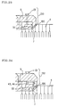
- Fig. 15, Fig. 16 and Fig. 18 are partially enlarged sectional views showing one example of the second honeycomb structure molding apparatus 140 of the present invention.
- the second honeycomb structure molding apparatus 140 of the present invention is an apparatus for making a honeycomb structure using as a molding material, for example, a ceramics powder which is mixed with a molding aid.
- the general view of the second honeycomb structure molding apparatus 140 is not shown, but is the same as the first honeycomb structure molding apparatus, except that the gap adjusting means is not provided.
- the second honeycomb structure molding apparatus 140 is characterized in that it has a reservoir part 151 comprising a ring dented part provided, at a press plate 145, outside by a given length L from the innermost end of a face opposing the downstream side of an outer peripheral part 152 of a spinneret 144 with facing a gap part 147.
- Volume of the dented part of the reservoir part 151 is preferably 1.8 times the volume of the gap part 147 which is inside from the reservoir part 151 and parallel to the spinneret.
- the volume of dented part of the reservoir part 151 means in more detail not only the volume of the dented part, but also the volume of the gap part facing the dented part of the press plate 145, and is the portion indicated by Q1 in Fig. 18. Furthermore, the volume of the gap part 147 which is inside from the reservoir part 151 and parallel to the spinneret means the portion indicated by Q2 in Fig. 18.
- a molding material is also extruded from the upstream side of the spinneret 144 to the downstream side through the spinneret 144 by an extruder (not shown) as in the conventional techniques, and the molding material extruded from slits 153 provided at the inner side part of the spinneret 144 which is opened at the downstream side forms a honeycomb structure comprising many cells.
- the molding material extruded from slits 154 provided at the outer peripheral part 152 of the spinneret 144 progresses with changing its progressing direction from the extrusion direction to the direction of the level difference part 155 with the honeycomb shape being ruptured by the action of the gap part 147 and again changes its progressing direction to the extrusion direction at the opening of the press plate 145 thereby forming an outer wall which surrounds the cells.
- the molding material extruded from slit 154 is adjusted in its amount to be extruded before reaching the level difference 155 by the buffer function of reservoir part 151. That is, even in the case of the slit 154 being provided at the same outer peripheral part 152, the molding material extruded from slit which is remoter from the level difference 155 changes in the speed of lowing the narrow gap part 147 with change of environment or change in fluidity caused by variation of raw materials and causes change in thickness of outer wall formed by the extruded molding material, but the change of speed of the molding material passing through the gap part 147 is absorbed by the reservoir part 151 provided in the vicinity of the innermost end of the press plate 145, and, thus, an outer wall of more uniform thickness can be formed.
- the volume of the dented part of the reservoir part 151 is 1.8 times the volume of the gap part 147 which is inside from the reservoir part 151 and parallel to the spinneret, measures can be made against the change of fluidity of the molding material which may occur. Under such conditions, according to the second honeycomb structure molding apparatus 140 of the present invention, variation of thickness of the outer wall can be controlled to the range of about ⁇ 0.05 mm.
- a temperature controlling means which can be added to a third honeycomb structure molding apparatus having the characteristics of the first honeycomb structure molding apparatus or the second honeycomb structure molding apparatus, or both the first honeycomb structure molding apparatus and the second honeycomb structure molding apparatus, namely, having the gap adjusting means and the reservoir part will be explained referring to Fig. 4.
- Fig. 4 is a sectional view showing one example of the honeycomb structure molding apparatus having a temperature controlling means.
- a temperature controlling means 46 comprises a hollow passage 43 provided in the press plate 45 and a water feeding device 41 which allows a circulating water of a desired temperature such cold water, warm water or the like to flow through the hollow passage 43 through a piping 42.
- a temperature controlling means 46 comprises a hollow passage 43 provided in the press plate 45 and a water feeding device 41 which allows a circulating water of a desired temperature such cold water, warm water or the like to flow through the hollow passage 43 through a piping 42.
- a heat insulator 49 between the press plate 45 and a press jig 48 so as to inhibit escape of heat to the press jig 48.
- the range of temperature control of this temperature controlling means 46 is preferably about 5-35°C. Furthermore, the temperature controlling means 46 is more preferably such that a temperature control meter is provided at one or both of the press plate 45 and spinneret 44 and a heating and cooling device capable of heating and cooling the temperature of circulating water is provided at water feeding device to impart an automatic temperature controlling function which controls the temperature of the circulating water based on the temperature measured by the temperature control meter.
- the temperature of the molding material passing through the gap part namely, the molding material per se which forms an outer wall can be controlled by this temperature controlling means 46. Therefore, it becomes possible to control the molding speed of the outer wall without changing fluidity caused by change of environment at use or variation of starting material.
- the molding material is heated to improve fluidity of the molding material for the formation of outer wall, and the molding speed is increased to allow to meet with the molding speed of the cell portion. As a result, occurrence of failure, namely, occurrence of burr can be inhibited.
- wavy wall may be formed because the molding speed of the outer wall is higher than that of cells, fluidity of the molding material for the formation of the outer wall is reduced to lower the molding speed to meet with the molding speed of the cell portion. In this way, occurrence of failure due to the formation of wavy wall can be inhibited.
- the honeycomb structure molding apparatus of the present invention can be constructed by suitable combination of the above-mentioned characteristics, namely, the gap adjusting means, the reservoir part and the temperature controlling means. Therefore, in conformity with the characteristics of the molding materials such as ceramics and metals, construction of apparatus can be selected which is low in cost and effective for inhibition of occurrence of failure in formation of outer wall.
- a molded article was molded from an extrusion molding machine, and it was examined whether failure in formation of outer wall such as formation of waviness (as shown in Fig. 10) or burrs (as shown in Fig. 12) occurred or not.
- failure in formation of outer wall such as formation of waviness (as shown in Fig. 10) or burrs (as shown in Fig. 12) occurred or not.
- the press plate provided with gap adjusting means or temperature controlling means as shown in the present invention is used, the occurrence of failure in formation of outer wall is inhibited by using the inhibition means. Extrusion length extruded during the time from inhibition of the failure in formation of outer layer being attained by the inhibition means until the next failure in formation of outer wall occurred was measured.
- the molding materials for extrusion molding were prepared in the following manner to obtain two kinds of molding materials A and B.
- an Fe-Cr-Al metallic honeycomb structure For making an Fe-Cr-Al metallic honeycomb structure, a given amount of an Fe-Cr-Al atomized powder was weighed to obtain a starting batch. Next, as a kneading step, to 100 mass % of the resulting starting batch were added 4 mass % of methyl cellulose and addition water, followed by carrying out kneading by a kneading apparatus (not shown) to obtain a kneaded product. At this kneading step, temperature of the kneading apparatus was controlled so that the temperature of the kneaded product reached 10°C.
- Extrusion molding was carried out using the molding material A by a honeycomb structure molding apparatus provided with a gap adjusting means 130 and having a level difference part 155 comprising an inclined plane of about 45° as shown in Fig. 19 with setting a spinneret 4 and a press plate 5 so that the width of gap of the gap part 7 was 0.3 mm, and evaluation on failure in formation of outer wall was conducted.
- Extrusion molding was carried out in the same manner as in Example 1, except that the molding material B was used, and evaluation on failure in formation of outer wall was conducted.
- Extrusion molding was carried out in the same manner as in Example 1, except that width of the gap of the gap part 7 was 0.6 mm, and evaluation on failure in formation of outer wall was conducted.
- a honeycomb structure molding apparatus provided with a gap adjusting means 130 and a temperature controlling means 46 and having a level difference part 155 comprising inclined plane of about 45° as shown in Fig. 20 was used.
- the temperature controlling means 46 allows a circulating water controlled in temperature to flow through hollow passage 43 provided in the press plate 5 from a water feeding device (not shown), thereby controlling the temperature of the press plate 5.
- Extrusion molding was carried out using the molding material A with setting the spinneret 4 and the press plate 5 so that width of the gap of the gap part 7 was 0.3 mm, and with the range of temperature control of the press plate 5 being 10-30°C. Evaluation on failure in formation of outer wall was conducted.
- Extrusion molding was carried out in the same manner as in Example 4, except that the molding material B was used, and evaluation on failure in formation of outer wall was conducted.
- Extrusion molding was carried out using the molding material A by a honeycomb structure molding apparatus provided with a reservoir part 151 and having the level difference part 155 comprising an inclined plane of about 45° as shown in Fig. 21 with setting a spinneret 4 and a press plate 5 so that the width of gap of the gap part 7 was 0.3 mm, and evaluation on failure in formation of outer wall was conducted.
- the volume Q1 of the dented portion of the reservoir part 151 and the volume Q2 of the gap part were, in more detail, volumes of the portions shown in Fig. 18.
- Extrusion molding was carried out using the molding material A by a honeycomb structure molding apparatus provided with reservoir part 151 and temperature controlling means 46 and having the level difference part 155 comprising an inclined plane of about 45° as shown in Fig. 22 with setting a spinneret 4 and a press plate 5 so that the width of gap of the gap part 7 was 0.3 mm and with the range of temperature control of the press plate 5 being 10-30°C., and evaluation on failure in formation of outer wall was conducted.
- the temperature controlling means 46 was the same as in Example 4, and the reservoir part 151 had the same size as in Example 6.
- Extrusion molding was carried out using the molding material A by a honeycomb structure molding apparatus provided with reservoir part 151 and gap adjusting means 130 and having the level difference part 155 comprising an inclined plane of about 45° as shown in Fig. 23 with setting a spinneret 4 and a press plate 5 so that the width of gap of the gap part 7 was 0.3 mm, and evaluation on failure in formation of outer wall was conducted.
- the reservoir part 151 had the same size as in Example 6.
- Extrusion molding was carried out using the molding material A by a honeycomb structure molding apparatus provided with the reservoir part 151, the temperature controlling means 46 and the gap adjusting means 130, and having the level difference part 155 comprising an inclined plane of about 45° as shown in Fig. 24 with setting the spinneret 4 and the press plate 5 so that the width of gap of the gap part 7 was 0.3 mm and with the range of temperature control of the press plate 5 being 10-30°C., and evaluation on failure in formation of outer wall was conducted.
- the temperature controlling means 46 was the same as in Example 4, and the reservoir part 151 had the same size as in Example 6.
- Extrusion molding was carried out in the same manner as in Example 1, except for using a honeycomb structure molding apparatus having a level difference part 165 comprising a vertical plane of about 90° as shown in Fig. 25, and evaluation on failure in formation of outer wall was conducted.
- Extrusion molding was carried out in the same manner as in Example 6, except for using a honeycomb structure molding apparatus having the level difference part 165 comprising a vertical plane of about 90° as shown in Fig. 26, and evaluation on failure in formation of outer wall was conducted.
- Extrusion molding was carried out in the same manner as in Example 1, except for using a honeycomb structure molding apparatus provided with a gap adjusting means 133 as shown in Fig. 30, and evaluation on failure in formation of outer wall was conducted.
- Extrusion molding was carried out in the same manner as in Example 9, except for using a honeycomb structure molding apparatus which was not provided with the temperature controlling means 46 in the press plate 5 in such a manner as opposing the level difference part 155 of the spinneret as shown in Fig. 24, but was provided with the temperature controlling means 46 at a flexible part 132 of the press plate 5 as shown in Fig. 31, and evaluation on failure in formation of outer wall was conducted.
- Extrusion molding was carried out using the molding material A by a honeycomb structure molding apparatus having the level difference part 155 comprising an inclined plane of about 45° as shown in Fig. 27 with setting the spinneret 4 and the press plate 5 so that the width of gap of the gap part 7 was 0.3 mm, and evaluation on failure in formation of outer wall was conducted.
- Extrusion molding was carried out in the same manner as in Comparative Example 1, except that the molding material B was used, and evaluation on failure in formation of outer wall was conducted.
- Extrusion molding was conducted in the same manner as in Example 7, except that the range of temperature control of the press plate 5 was 36-40°C, and evaluation on failure in formation of outer wall was conducted.
- Extrusion molding was carried out in the same manner as in Example 7, except that the range of temperature control of the press plate 5 was 0-4°C, and evaluation on failure in formation of outer wall was conducted.
- Extrusion molding was carried out in the same manner as in Example 9, except that the range of temperature control of the press plate 5 was 36-40°C, and evaluation on failure in formation of outer wall was conducted.
- Extrusion molding was carried out in the same manner as in Comparative Example 1, except for using a honeycomb structure molding apparatus having the level difference part 165 comprising a vertical plane of about 90° as shown in Fig. 28, and evaluation on failure in formation of outer wall was conducted.
- Extrusion molding was carried out in the same manner as in Comparative Example 1, except for using a honeycomb structure molding apparatus provided with a temperature controlling means 46 as shown in Fig. 29, and evaluation on failure in formation of outer wall was conducted.
- the honeycomb structure molding apparatus and the molding method of the present invention it becomes possible to easily perform fine adjustment or keeping constant of molding speed of the outer wall of the honeycomb structure, whereby failures in formation of outer wall, such as formation of burrs, wavy wall, distortion, etc. can be inhibited. Therefore, the present invention has the excellent effects that the honeycomb structure can be made in high yield, and the production cost can be further reduced.
- a honeycomb structure molding apparatus 1 having a spinneret 4 provided with a back pore part 3 for introducing a molding material and a slit part 2 for extruding the molding material, and a press plate 5 for fixing the spinneret 4, in which the spinneret 4 comprises an inner side part 11 and an outer peripheral part 12, the inner side part 11 is protruded to the downstream side to form a level difference part 15 between the inner side part 11 and the outer peripheral part 15, the press plate 5 is opened opposing the inner side part 12 of the spinneret 4 and presses the downstream side of the outer peripheral part 12 of the spinneret 4 through a gap part 7, and there is provided a gap adjusting means 130 capable of changing width of the gap of the gap part 7.
Landscapes
- Engineering & Computer Science (AREA)
- Manufacturing & Machinery (AREA)
- Chemical & Material Sciences (AREA)
- Ceramic Engineering (AREA)
- Mechanical Engineering (AREA)
- Press-Shaping Or Shaping Using Conveyers (AREA)
Abstract
Description
| Molding material | Av. particle diameter (µm) | Chemical analysis value (%) | ||||||
| Ignition loss | SiO2 | Al2O3 | MgO | TiO2 | Fe2O3 | CaO + Na2O +K2O | ||
| Talc | 6.7 | 5.2 | 61.7 | 0.4 | 30.7 | - | 1.3 | 0.2 |
| Kaolin | 21.3 | 13.5 | 45.5 | 38.5 | - | 1.3 | 0.5 | 0.1 |
| Al(OH)3 | 0.6 | 34 | - | 65.6 | - | - | - | 0.3 |
| Molding material | Average Particle Diameter (µm) | Chemical analysis value (%) | |||||
| Fe | Cr | Al | Si | Ni | Ca | ||
| Atomized Fe-Cr-Al powder | 13.4 | 76.5 | 16.6 | 6.9 | - | - | - |


Claims (20)
- A honeycomb structure molding apparatus for extrusion molding a honeycomb structure, characterized in that it has at least a spinneret provided with a back pore part for introducing a molding material and a slit part for extruding the molding material, and a press plate for fixing the spinneret, the spinneret comprises an inner side part and an outer peripheral part, the inner side part is protruded to the downstream side to form a level difference part between the inner side part and the outer peripheral part, the press plate is opened opposing the inner side part of the spinneret and presses the downstream side of the outer peripheral part of the spinneret through a gap part formed between the spinneret and the press plate, and there is provided a gap adjusting means capable of changing width of the gap of the gap part.
- A honeycomb structure molding apparatus according to claim 1, wherein the molding material is a mixture comprising at least a ceramics powder and/or a metal powder and a molding aid.
- A honeycomb structure molding apparatus according to claim 1 or 2, wherein the gap adjusting means comprises a flexible part provided at the press plate and an adjusting instrument flexing the flexible part, said adjusting means flexing the flexible part to fix it at a desired position and adjust the width of the gap.
- A honeycomb structure molding apparatus according to claim 3, wherein the adjusting instrument is a screw which pierces through the press plate and whose head is exposed on the upper surface of the press plate.
- A honeycomb structure molding apparatus according to claim 3 or 4, wherein the gap adjusting means is provided at an inner peripheral end part of the press plate and opposing the innermost part of the outer peripheral part of the spinneret, and a plurality of the gap adjusting means are provided dividing the inner periphery at equal intervals.
- A honeycomb structure molding apparatus according to any one of claims 1-5, wherein the range of adjustment of the width of the gap by the gap adjusting means is about 0-0.50 mm.
- A honeycomb structure molding apparatus for extrusion molding a honeycomb structure, characterized in that it has at least a spinneret provided with a back pore part for introducing a molding material and a slit part for extruding the molding material, and a press plate for fixing the spinneret, the spinneret comprises an inner side part and an outer peripheral part, the inner side part is protruded to the downstream side to form a level difference part between the inner side part and the outer peripheral part, the press plate is opened opposing the inner side part of the spinneret and presses the downstream side of the outer peripheral part of the spinneret through a gap part formed between the spinneret and the press plate, and a reservoir part comprising a ring dented part is provided in the press plate at the position outside by a given length L facing the gap part from the innermost end of the face opposing the downstream side of the outer periphery part of the spinneret.
- A honeycomb structure molding apparatus according to claim 7, wherein the volume of the dented portion of the reservoir part is 1.8 times the volume of the gap part which is inside the reservoir part and parallel to the spinneret.
- A honeycomb structure molding apparatus according to claim 7, wherein the gap adjusting means of claim 1 is additionally provided.
- A honeycomb structure molding apparatus according to any one of claims 1-9, wherein a temperature controlling means capable of changing the temperature of the molding material is provided.
- A honeycomb structure molding apparatus according to claim 10, wherein the temperature controlling means comprises a hollow passage provided in the press plate and a water feeding device which allows a circulating water of a desired temperature to flow through the hollow passage, and the temperature of the press plate is changed to control the temperature of the molding material.
- A honeycomb structure molding apparatus according to claim 10 or 11, wherein the range of temperature control by the temperature controlling means is preferably 5-35°C.
- A honeycomb structure molding apparatus according to any one of claims 10-12, wherein the temperature controlling means has a temperature control meter provided at the press plate and/or the spinneret.
- A honeycomb structure molding apparatus according to claim 1, 7 or 9, wherein the level difference part has a tapered spinneret having an inclined plane of about 30-60° .
- A honeycomb structure molding apparatus according to claim 1, 7 or 9, wherein the level difference part has a right-angled spinneret having an inclined plane of about 90°.
- A honeycomb structure molding apparatus according to any one of claims 1-15, the honeycomb structure is supported on the surface of cell partition wall and/or the inner surface of the pores inside the partition wall and used as a catalyst carrier for purification of exhaust gas of automobiles.
- A method for molding a honeycomb structure which comprises extrusion molding a molding material containing at least a ceramics powder and/or a metallic powder and a molding aid to obtain a honeycomb structure, characterized in that there is used a honeycomb structure molding apparatus having at least a spinneret provided with a back pore part for introducing a molding material and a slit part for extruding the molding material and a press plate for fixing the spinneret, the spinneret comprising an inner side part and an outer peripheral part, the inner side part being protruded to the downstream side to form a level difference part between the inner side part and the outer peripheral part, the press plate being opened opposite to the inner side part of the spinneret and pressing the downstream side of the outer peripheral part of the spinneret through a gap part formed between the spinneret and the press plate, and the molding material is extruded with adjusting the width of the gap of the gap part, thereby to form an outer wall having a uniform thickness.
- A method according to claim 17, wherein variation of thickness of the outer wall is within about ±0.05 mm.
- A method for molding a honeycomb structure which comprises extrusion molding a molding material containing at least a ceramics powder and/or a metallic powder and a molding aid to obtain a honeycomb structure, characterized in that there is used a honeycomb structure molding apparatus having at least a spinneret provided with a back pore part for introducing a molding material and a slit part for extruding the molding material and a press plate for fixing the spinneret, the spinneret comprising an inner side part and an outer peripheral part, the inner side part being protruded to the downstream side to form a level difference part between the inner side part and the outer peripheral part, the press plate being opened opposite to the inner side part of the spinneret and pressing the downstream side of the outer peripheral part of the spinneret through a gap part formed between the spinneret and the press plate, a reservoir part comprising a ring dented part being provided in the press plate at the position outside by a given length L facing the gap part from the innermost end of the face opposing the downstream side of the outer peripheral part of the spinneret, and the molding material is extruded through the reservoir part, thereby to form an outer wall having a uniform thickness.
- A method according to claim 19, wherein variation of thickness of the outer wall is within about ±0.05 mm.
Applications Claiming Priority (2)
| Application Number | Priority Date | Filing Date | Title |
|---|---|---|---|
| JP2001093414A JP2002283326A (en) | 2001-03-28 | 2001-03-28 | Honeycomb structure forming apparatus and forming method |
| JP2001093414 | 2001-03-28 |
Publications (2)
| Publication Number | Publication Date |
|---|---|
| EP1245359A2 true EP1245359A2 (en) | 2002-10-02 |
| EP1245359A3 EP1245359A3 (en) | 2004-01-14 |
Family
ID=18947749
Family Applications (1)
| Application Number | Title | Priority Date | Filing Date |
|---|---|---|---|
| EP02005915A Withdrawn EP1245359A3 (en) | 2001-03-28 | 2002-03-14 | Apparatus for molding honeycomb structure and molding method |
Country Status (3)
| Country | Link |
|---|---|
| US (1) | US6854969B2 (en) |
| EP (1) | EP1245359A3 (en) |
| JP (1) | JP2002283326A (en) |
Cited By (3)
| Publication number | Priority date | Publication date | Assignee | Title |
|---|---|---|---|---|
| WO2010144769A3 (en) * | 2009-06-12 | 2012-04-12 | Corning Incorporated | Dies for forming extrusions with thick and thin walls |
| WO2013169629A3 (en) * | 2012-05-08 | 2014-01-09 | Corning Incorporated | Honeycomb extrusion apparatus and methods |
| CN104487216A (en) * | 2012-05-08 | 2015-04-01 | 康宁股份有限公司 | Honeycomb extrusion apparatus and method |
Families Citing this family (12)
| Publication number | Priority date | Publication date | Assignee | Title |
|---|---|---|---|---|
| US6991448B2 (en) * | 2003-04-01 | 2006-01-31 | Corning Incorporated | Apparatus for extruding honeycomb bodies |
| US7112050B2 (en) * | 2003-06-26 | 2006-09-26 | Corning Incorporated | Extrusion die for making a double-skin honeycomb substrate |
| US7914724B2 (en) | 2005-07-29 | 2011-03-29 | Corning Incorporated | Methods for extruding a honeycomb article with a skin surrrounding a central cellular structure |
| JP2009023318A (en) | 2007-07-24 | 2009-02-05 | Denso Corp | Mold for forming honeycomb structure |
| JP2009023317A (en) * | 2007-07-24 | 2009-02-05 | Denso Corp | Mold for forming honeycomb structure |
| JP2009023319A (en) * | 2007-07-24 | 2009-02-05 | Denso Corp | Mold for forming honeycomb structure |
| JP2009023316A (en) * | 2007-07-24 | 2009-02-05 | Denso Corp | Mold for forming honeycomb structure |
| US20090075547A1 (en) * | 2007-09-19 | 2009-03-19 | Rotter Matin J | Cleaning pads with abrasive loaded filaments and anti-microbial agent |
| US8348659B2 (en) * | 2010-02-25 | 2013-01-08 | Corning Incorporated | Apparatus and method for forming skin on a ceramic body by extrusion |
| EP2857164B1 (en) * | 2012-06-04 | 2019-03-20 | NGK Insulators, Ltd. | Spinneret for molding honeycomb structure and manufacturing method therefor |
| US10384369B2 (en) * | 2012-11-30 | 2019-08-20 | Corning Incorporated | Extrusion systems and methods with temperature control |
| US11292152B2 (en) * | 2015-11-20 | 2022-04-05 | Corning Incorporated | Extrusion dies for honeycomb body |
Family Cites Families (18)
| Publication number | Priority date | Publication date | Assignee | Title |
|---|---|---|---|---|
| US3905743A (en) * | 1971-11-09 | 1975-09-16 | Corning Glass Works | Extrusion apparatus for forming thin-walled honeycomb structures |
| US3884611A (en) * | 1973-10-24 | 1975-05-20 | Leesona Corp | Extrusion die |
| US3947214A (en) * | 1974-12-13 | 1976-03-30 | Corning Glass Works | Extrusion die mask |
| JPS5838083B2 (en) * | 1980-01-22 | 1983-08-20 | 株式会社日本自動車部品総合研究所 | Die equipment for extrusion molding of honeycomb structures |
| JPS57157706A (en) * | 1981-03-25 | 1982-09-29 | Nippon Soken | Die for molding honeycomb |
| US4551295A (en) * | 1984-04-26 | 1985-11-05 | Corning Glass Works | Process for mixing and extruding ceramic materials |
| JPS615915A (en) * | 1984-06-19 | 1986-01-11 | Sakai Chem Ind Co Ltd | Continuous extrusion of honeycomb molding and continuous extruding die used therefor |
| DE3510182A1 (en) * | 1985-03-21 | 1986-10-09 | Hoechst CeramTec AG, 8672 Selb | EXTRUDING DEVICE FOR PRODUCING HONEYCOMB BODIES |
| DE3510181A1 (en) * | 1985-03-21 | 1986-10-02 | Hoechst CeramTec AG, 8672 Selb | EXTRUDING DEVICE FOR PRODUCING HONEYCOMB BODIES |
| DE3740088C1 (en) * | 1987-11-26 | 1988-11-10 | Reifenhaeuser Masch | Process for producing a film from thermoplastic |
| US5089203A (en) * | 1991-02-12 | 1992-02-18 | Corning Incorporated | Method and apparatus for forming an outer skin or honeycomb structures |
| US5679383B1 (en) * | 1994-02-04 | 1999-01-05 | Extrusion Dies Inc | Dual flexible lip extrusion apparatus |
| US5466415A (en) * | 1994-10-20 | 1995-11-14 | Corning Incorporated | Extrusion of metal honeycombs |
| JP3220971B2 (en) * | 1995-09-19 | 2001-10-22 | 株式会社デンソー | Honeycomb structure extrusion device |
| JP3814849B2 (en) * | 1995-09-28 | 2006-08-30 | 株式会社デンソー | Die for forming honeycomb structure and method for forming honeycomb structure using the same |
| JP3635780B2 (en) * | 1996-04-08 | 2005-04-06 | 株式会社デンソー | Honeycomb structure forming apparatus and forming method |
| JP3701802B2 (en) * | 1998-10-29 | 2005-10-05 | 日本碍子株式会社 | Die for honeycomb manufacturing |
| JP3701801B2 (en) * | 1998-10-29 | 2005-10-05 | 日本碍子株式会社 | Die for honeycomb manufacturing |
-
2001
- 2001-03-28 JP JP2001093414A patent/JP2002283326A/en active Pending
-
2002
- 2002-03-14 EP EP02005915A patent/EP1245359A3/en not_active Withdrawn
- 2002-03-22 US US10/102,737 patent/US6854969B2/en not_active Expired - Lifetime
Cited By (8)
| Publication number | Priority date | Publication date | Assignee | Title |
|---|---|---|---|---|
| WO2010144769A3 (en) * | 2009-06-12 | 2012-04-12 | Corning Incorporated | Dies for forming extrusions with thick and thin walls |
| US8449283B2 (en) | 2009-06-12 | 2013-05-28 | Corning Incorporated | Dies for forming extrusions with thick and thin walls |
| WO2013169629A3 (en) * | 2012-05-08 | 2014-01-09 | Corning Incorporated | Honeycomb extrusion apparatus and methods |
| CN104487216A (en) * | 2012-05-08 | 2015-04-01 | 康宁股份有限公司 | Honeycomb extrusion apparatus and method |
| CN104619482A (en) * | 2012-05-08 | 2015-05-13 | 康宁股份有限公司 | Honeycomb extrusion apparatus and methods |
| CN104487216B (en) * | 2012-05-08 | 2016-08-24 | 康宁股份有限公司 | Honeycomb extrusion apparatus and method |
| US9475245B2 (en) | 2012-05-08 | 2016-10-25 | Corning Incorporated | Honeycomb extrusion apparatus and methods |
| CN104619482B (en) * | 2012-05-08 | 2018-11-09 | 康宁股份有限公司 | Honeycomb pressurizing unit and method |
Also Published As
| Publication number | Publication date |
|---|---|
| US6854969B2 (en) | 2005-02-15 |
| US20030001308A1 (en) | 2003-01-02 |
| JP2002283326A (en) | 2002-10-03 |
| EP1245359A3 (en) | 2004-01-14 |
Similar Documents
| Publication | Publication Date | Title |
|---|---|---|
| US6854969B2 (en) | Apparatus for molding honeycomb structure and molding method | |
| US6814562B2 (en) | Apparatus for molding a honeycomb structure | |
| EP2082856B1 (en) | Mold for extrusion forming of ceramic articles | |
| CN110834095B (en) | Method for selective laser melting forming of compact-loose integrated die part | |
| EP0232621B1 (en) | Catalyst carrier of cordierite honeycomb structure and method of producing the same | |
| CN100436106C (en) | Honeycomb-shape mouthpiece forextruding for mation and production method thereof | |
| US20030166450A1 (en) | Honeycomb ceramics structure and method for preparation thereof | |
| WO2001016049A1 (en) | Fabrication of ultra-thinwall cordierite structures | |
| EP2221156B1 (en) | Die for forming honeycomb structure | |
| EP1341650B1 (en) | Method for extruding ceramic honeycombs | |
| US7594807B2 (en) | Twin-screw extruder | |
| JP2018103122A (en) | Method for manufacturing porous honeycomb filter | |
| CN114433422A (en) | Coating die head and coating device | |
| EP2233265B1 (en) | Extrusion-forming device and method for manufacturing formed article by use of the device | |
| EP2857163B1 (en) | Spinneret for molding honeycomb structure and manufacturing method therefor | |
| CA1146023A (en) | Method of producing a die for extruding a ceramic batch into a honeycomb structural body | |
| EP1355865B1 (en) | Fabrication of ultra-thinwall cordierite structures | |
| JPH04135824A (en) | Ejection nozzle to manufacture a hollow plate | |
| EP1090671B1 (en) | Honeycomb type gas separating membrane | |
| FI82212C (en) | ANORDNING OCH FOERFARANDE FOER FRAMSTAELLNING AV EN MULTI-CELL-SKUMPLASTSKIVA AV THERMOPLAST. | |
| US20090028982A1 (en) | Extrusion die for molding honeycomb structures | |
| CN212144497U (en) | Multi-zone temperature control and air inlet device for walking beam type continuous degreasing sintering furnace | |
| JP4233623B2 (en) | Die for forming honeycomb and manufacturing method thereof | |
| CN223576349U (en) | A hot-bending double-curved glass mold | |
| EP1481779B1 (en) | Forming JIG and method for producing formed body using same |
Legal Events
| Date | Code | Title | Description |
|---|---|---|---|
| PUAI | Public reference made under article 153(3) epc to a published international application that has entered the european phase |
Free format text: ORIGINAL CODE: 0009012 |
|
| AK | Designated contracting states |
Kind code of ref document: A2 Designated state(s): AT BE CH CY DE DK ES FI FR GB GR IE IT LI LU MC NL PT SE TR |
|
| AX | Request for extension of the european patent |
Free format text: AL;LT;LV;MK;RO;SI |
|
| PUAL | Search report despatched |
Free format text: ORIGINAL CODE: 0009013 |
|
| AK | Designated contracting states |
Kind code of ref document: A3 Designated state(s): AT BE CH CY DE DK ES FI FR GB GR IE IT LI LU MC NL PT SE TR |
|
| AX | Request for extension of the european patent |
Extension state: AL LT LV MK RO SI |
|
| 17P | Request for examination filed |
Effective date: 20040625 |
|
| AKX | Designation fees paid |
Designated state(s): BE DE |
|
| 17Q | First examination report despatched |
Effective date: 20100713 |
|
| STAA | Information on the status of an ep patent application or granted ep patent |
Free format text: STATUS: THE APPLICATION IS DEEMED TO BE WITHDRAWN |
|
| 18D | Application deemed to be withdrawn |
Effective date: 20101124 |