EP1244580B1 - Contact washer system and method for controlling a windscreen wiper motor - Google Patents
Contact washer system and method for controlling a windscreen wiper motor Download PDFInfo
- Publication number
- EP1244580B1 EP1244580B1 EP01982147A EP01982147A EP1244580B1 EP 1244580 B1 EP1244580 B1 EP 1244580B1 EP 01982147 A EP01982147 A EP 01982147A EP 01982147 A EP01982147 A EP 01982147A EP 1244580 B1 EP1244580 B1 EP 1244580B1
- Authority
- EP
- European Patent Office
- Prior art keywords
- contact
- track
- electrically conductive
- contact element
- conductive region
- Prior art date
- Legal status (The legal status is an assumption and is not a legal conclusion. Google has not performed a legal analysis and makes no representation as to the accuracy of the status listed.)
- Expired - Lifetime
Links
- 238000000034 method Methods 0.000 title claims description 11
- 238000010586 diagram Methods 0.000 description 8
- 238000004519 manufacturing process Methods 0.000 description 4
- 235000010627 Phaseolus vulgaris Nutrition 0.000 description 1
- 244000046052 Phaseolus vulgaris Species 0.000 description 1
- 239000000969 carrier Substances 0.000 description 1
- 238000004140 cleaning Methods 0.000 description 1
- 238000010276 construction Methods 0.000 description 1
- 238000005516 engineering process Methods 0.000 description 1
- 230000001360 synchronised effect Effects 0.000 description 1
Images


Classifications
-
- B—PERFORMING OPERATIONS; TRANSPORTING
- B60—VEHICLES IN GENERAL
- B60S—SERVICING, CLEANING, REPAIRING, SUPPORTING, LIFTING, OR MANOEUVRING OF VEHICLES, NOT OTHERWISE PROVIDED FOR
- B60S1/00—Cleaning of vehicles
- B60S1/02—Cleaning windscreens, windows or optical devices
- B60S1/04—Wipers or the like, e.g. scrapers
- B60S1/06—Wipers or the like, e.g. scrapers characterised by the drive
- B60S1/08—Wipers or the like, e.g. scrapers characterised by the drive electrically driven
-
- H—ELECTRICITY
- H01—ELECTRIC ELEMENTS
- H01H—ELECTRIC SWITCHES; RELAYS; SELECTORS; EMERGENCY PROTECTIVE DEVICES
- H01H19/00—Switches operated by an operating part which is rotatable about a longitudinal axis thereof and which is acted upon directly by a solid body external to the switch, e.g. by a hand
- H01H19/54—Switches operated by an operating part which is rotatable about a longitudinal axis thereof and which is acted upon directly by a solid body external to the switch, e.g. by a hand the operating part having at least five or an unspecified number of operative positions
- H01H19/56—Angularly-movable actuating part carrying contacts, e.g. drum switch
- H01H19/58—Angularly-movable actuating part carrying contacts, e.g. drum switch having only axial contact pressure, e.g. disc switch, wafer switch
- H01H19/585—Angularly-movable actuating part carrying contacts, e.g. drum switch having only axial contact pressure, e.g. disc switch, wafer switch provided with printed circuit contacts
Definitions
- the invention relates to a contact disc system with a rotatable contact disc and a plurality of contact elements, wherein the contact disc has a plurality of tracks and each contact element is associated with a web.
- the invention further relates to a method for controlling a Windscreen wiper motor using a contact disk system with a rotatable contact disc and a plurality of contact elements, wherein the contact disc more Has webs and each contact element of a web assigned.
- the invention relates to a Windscreen wiper motor, which is a contact disk system with a rotatable contact disc and a plurality of contact elements comprising, wherein the contact disc a plurality of webs has and assigned each contact element of a web is.
- Windscreen wiper devices with generic contact disk systems and generic methods for controlling of windscreen wiper motors are especially for cleaning known from motor vehicle windows.
- the windscreen wiper devices are replaced by a Operated switch, which is inside the motor vehicle is located, this switch usually as a steering column switch is designed.
- a steering column switch By moving the steering column switch can the windshield wiper device of a switched off state in at least one operating state be transferred. Most are operating conditions with several windscreen wiper speeds and an interval circuit realized.
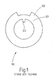
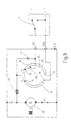
- FIG. 1 shows a contact disk 110 which in a contact disc system of the prior art is used.
- a contact disk 110th is installed in generic wiper motors so that they are in sync with the wiper motor rotates.
- the contact disk 110 provides a contact three contact elements ago, each on a train slide the contact disc 110.
- a first contact element slides on the outer panel 120, which is an interruption having.
- a second contact element slides on the inner track 122, which realizes as a short track is, and a third contact element slides on one middle track 121, which is continuous.
- GB-A-2 313 452 shows a contact disc with two beans.
- the invention is based on the generic contact disk system characterized in that the contact disc two tracks and that there are two selected contact elements the multiple contact elements always on the same electrical potential and on the same track slide. This way it is also with a two lane Contact disc possible, an electric current flow until reaching the parking position of the windscreen wiper or until shortly before reaching the parking position maintain. Because of the contact disc With two tracks, it has a smaller size or radial width, which benefits in terms on the entire size of the windscreen wiper motor and in terms of the manufacturing process brings.
- the selected contact elements slide on a first track, which is an electrically conductive and has an electrically insulating region, and at least a contact element of the selected contact elements is connected to the electrically conductive region. If the windscreen wiper motor by turning the steering column switch switched off, so will at least one the selected contact elements an electrical Maintain connection to the wiper motor, as always at least one of the selected contact elements with the electrically conductive region of the first path in conjunction stands.
- the electrically insulating region of the first Web through an interruption of a conductive path realized, and have the selected contact elements a distance greater than the break the first track.
- the electrically insulating area can through a cutout with radial boundaries will be realized. Is the opening angle of this interruption less than the distance angle of the selected one Contact elements, this way it is ensured that always one of the selected contact elements in conjunction with the electrically conductive region the first train is located.
- first further contact element slides on the first track.
- This first more Contact element serves to make an electrical connection between the contact disc and the positive pole of Maintain vehicle battery.
- the steering column switch in the off Position is an electrical connection over the first further contact element and at least one of the selected Contact elements between the positive pole of the battery and the engine. Only when the first more Contact element the electrically conductive region of first train leaves and is in the insulating area of the first track is located, the current flow is interrupted.
- a second track a electrically insulating area and an electrically conductive Has area and if on the second track a second further contact element slides.
- This contact element serves to provide an electrical short circuit of the To realize motor and thereby the engine when reaching to actively brake the parking position.
- the interruption of the first web, the electrically conductive area of the second lane, the first further contact element and the second further contact element arranged so that a state exists, in which neither the first further contact element nor the second additional contact element with an electric conductive area of the first orbit respectively the second lane are connected.
- this state is the current flow in the circuit of the windshield wiper motor although already interrupted.
- the engine and the contact disk However, they spin because of their inertia further.
- the angular range, which from the electrically conductive region of the second Track is less than the angular range, which of the electrically insulating region of the first Track is covered.
- the contact elements are contact springs. On This way, a secure contact between the contact disc and the contact elements made.
- the invention is based on the generic method thereby on that for controlling a windshield wiper motor a contact disk system according to the invention is used becomes. In this way, the advantages of the invention Contact disk system by a control method implemented.
- the invention is based on the generic windscreen wiper motor in that it is an inventive Contact disc has. This puts the windscreen wiper motor all advantages of the contact disc according to the invention and the method according to the invention. Especially advantageous is that a wiper motor with reduced Frame size can be produced.
- the invention is based on the surprising finding that it is due to a suitable arrangement of contact elements and a suitable geometric design a contact disc is possible, the functions of a three-blade contact disc, as in wiper motors
- the prior art also uses to allow with a two-lobed contact disc. Therefore can windscreen wiper motors according to the invention smaller size can be produced. In particular, can the manufacturing process can be simplified because no turning of the motor on the workpiece carriers of the assembly line more is needed.
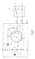
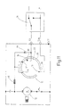
- FIG. 2 shows a contact disk system according to the invention in a top view.
- the contact disk system comprises a contact disk 10 and a plurality of contact elements 12, 14, 16, 18.
- the contact elements 12, 14, 16, 18 are as Contact springs designed.
- the contact disc 10 has two Webs 20, 22.
- the first web 20 has a relatively long electrically conductive region 24 and a comparatively short electrically insulating region 26 which passes through an interruption of the web 20 is realized.
- the first Web 20 is located in the radial direction outside the second Track 22.
- This second track 22 has a relatively long electrically insulating region 28 and a comparatively short electrically conductive area 30.
- the electric conductive region 30 is on as a short extension the electrically conductive region 24 of the first web 20 realized.
- Two contact elements 12, 14 of the plurality of contact elements 12, 14, 16, 18, which as selected contact elements 12, 14 are referred to their contact points 36, 38 a distance angle, which is greater than the break 26 of the first Lane 20. In this way always at least one of the Contact elements 12, 14 with the electrically conductive region 24 of the first web 20 in conjunction.
- the first more Contact element 16 slides on the first track 20.
- the second further contact element 18 slides on the second track 22.
- the angular range of the interruption 26 of the first web 20 is covered is greater than the angular range, which of the electric conductive region 30 of the second path is covered.
- the Contact point 40 of the first further contact element 16 and the pad 42 of the second further contact element 18 and the interruption 26 of the first web 20 and the electrically conductive region 30 of the second web 22 are arranged to each other so that there is a state in which neither the first further contact element 16 nor the second further contact element 18 with their respective railways communicate. Also is the Arrangement of the first further contact element 16 and the second further contact element 18 and the interruption 26 of the first track 20 and the electrically conductive Area 30 of the second path 22 is chosen so that a state exists, wherein the second further contact element 18 with the electrically conductive portion 30 of the second Rail 22 communicates while the first one more Contact element 16 in the electrically insulating region 26 of the first web 20 is located and thus no electrical Contact with the contact disk 10 has.
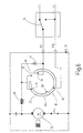
- FIG. 3 shows an electrical circuit with a device according to the invention Contact disk system in a switched on Status.
- a switch 34 which is generally referred to as Steering column switch is formed, provides a connection between the terminal 53 and the positive terminal of the vehicle battery ago. In this way lies on the terminal 53, a Reverse polarity protection diode 44 and a coil 46, the positive potential to the engine 32. This is independent of the Position of the contact disc 10 with respect to the contact elements 12, 14, 16, 18, in the present case an arbitrary one Snapshot of the synchronous with the motor 32 rotating Contact disk 10 is shown.
- FIG. 4 shows an equivalent circuit diagram of the circuit according to FIG Figure 3. It is shown that the terminal 53 always over the switch 34 is at positive potential.
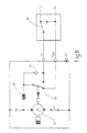
- Figure 5 shows an electrical circuit with an inventive Contact disk system in a first intermediate state.
- the Switch 34 has been folded so that now by the Switch 34 connects to the negative pole of the battery is present.
- the engine 32 is still the positive potential via the terminal 53a, the contact element 16, the contact disc 10 and the contact element 12th fed.
- the contact element 14 in the electric insulating region of the first web 20 of the contact disc 10. Because the distance between the selected contact elements 12, 14 is greater than the interruption 26 of the first web 20 of the contact element 10, is always a Maintain connection of the contact disc 10 to the motor 32.
- the second further contact element 18, which via terminal 53 is at negative potential, is not related to the contact disc, as it is in the electrically insulating region of the second path 22 is located.
- Figure 6 shows an electrical circuit with an inventive Contact disk system in a second intermediate state.
- This second intermediate state corresponds apart from the first intermediate state according to FIG. 5, that the contact of the positive pole now over the other selected contact element 14 is produced.
- Figure 7 shows an electrical circuit with an inventive Contact disk system in a third intermediate state.
- This third intermediate state also corresponds the first intermediate state according to FIG. 5 and the second intermediate state according to Figure 6, except that the Connection between the positive pole and the motor 32 at the Snapshot according to Figure 7 through both selected contact elements 12, 14 is maintained.
- FIG. 8 shows an equivalent circuit diagram of the circuits according to FIG Figures 5 to 7. In all states is the positive pole via the terminal 53a with the motor in conjunction, so that its operation will be maintained.
- FIG. 9 shows an electrical circuit with a device according to the invention Contact disk system in a fourth intermediate state.
- This fourth intermediate state makes a difference electrically from the first intermediate state, the second Intermediate state and the third intermediate state.
- the fourth intermediate state according to FIG. 9 is located the first further contact element 16 in the electrically insulating Region 26 of the first web 20. Therefore, the positive lies Potential no longer on the selected contact elements 12, 14, so no voltage on the motor 32 is applied.
- the second further contact element 18 is located in the electrically insulating region of second track 22, but shortly before contacting the electrically conductive area. Based on the condition According to FIG. 9, a further rotation of the contact disk takes place due to the inertia of the components involved.
- FIG. 10 shows an equivalent circuit diagram of the circuit according to FIG. 9. It is shown that neither the clamp 53a still the terminal 53 with the engine in connection. This means that neither a positive potential for the Normal operation of the motor 32 is applied. There is also no negative potential to the motor 32, which the motor 32nd was short circuit.
- Figure 11 shows an electrical circuit with an inventive Contact disk system in a switched off Status.
- the contact element 16 in the electrically insulating Area 26 of the web 20.
- the contact element 13 at the snapshot according to FIG. 11 in the electrically conductive region 30 of the second track 22.
- the motor 32 is short-circuited and thus actively braked.
- the windshield wiper is in parking position.
- FIG. 12 shows an equivalent circuit diagram of the circuit according to FIG. 11. It can be seen that the switch, which the contact disk 10 symbolizes a connection of the Motors 32 with the negative pole manufactures, so this shorted.
Description
Die Erfindung betrifft ein Kontaktscheibensystem mit einer drehbaren Kontaktscheibe und mehreren Kontaktelementen, wobei die Kontaktscheibe mehrere Bahnen aufweist und jedes Kontaktelement einer Bahn zugeordnet ist. Die Erfindung betrifft ferner ein Verfahren zum steuern eines Scheibenwischermotors unter Verwendung eines Kontaktscheibensystems mit einer drehbaren Kontaktscheibe und mehreren Kontaktelementen, wobei die Kontaktscheibe mehrere Bahnen aufweist und jedes Kontaktelement einer Bahn zugeordnet ist. Weiterhin betrifft die Erfindung einen Scheibenwischermotor, welcher ein Kontaktscheibensystem mit einer drehbaren Kontaktscheibe und mehreren Kontaktelementen umfasst, wobei die Kontaktscheibe mehrere Bahnen aufweist und jedes Kontaktelement einer Bahn zugeordnet ist.The invention relates to a contact disc system with a rotatable contact disc and a plurality of contact elements, wherein the contact disc has a plurality of tracks and each contact element is associated with a web. The invention further relates to a method for controlling a Windscreen wiper motor using a contact disk system with a rotatable contact disc and a plurality of contact elements, wherein the contact disc more Has webs and each contact element of a web assigned. Furthermore, the invention relates to a Windscreen wiper motor, which is a contact disk system with a rotatable contact disc and a plurality of contact elements comprising, wherein the contact disc a plurality of webs has and assigned each contact element of a web is.
Scheibenwischervorrichtungen mit gattungsgemäßen Kontaktscheibensystemen sowie gattungsgemäße Verfahren zum Steuern von Scheibenwischermotoren sind insbesondere zur Reinigung von Kraftfahrzeugscheiben bekannt. Üblicherweise werden die Scheibenwischervorrichtungen durch einen Schalter bedient, welcher sich im Inneren des Kraftfahrzeuges befindet, wobei dieser Schalter meist als Lenkstockschalter ausgelegt ist. Durch Umlegen des Lenkstockschalters kann die Scheibenwischervorrichtung von einem ausgeschalteten Zustand in mindestens einen Betriebszustand überführt werden. Meist sind Betriebszustände mit mehreren Scheibenwischergeschwindigkeiten und eine Intervallschaltung realisiert.Windscreen wiper devices with generic contact disk systems and generic methods for controlling of windscreen wiper motors are especially for cleaning known from motor vehicle windows. Usually the windscreen wiper devices are replaced by a Operated switch, which is inside the motor vehicle is located, this switch usually as a steering column switch is designed. By moving the steering column switch can the windshield wiper device of a switched off state in at least one operating state be transferred. Most are operating conditions with several windscreen wiper speeds and an interval circuit realized.
Um sicherzustellen, dass die Scheibenwischer nach dem Abschalten durch den Lenkstockschalter nicht in einer Zwischenstellung stehenbleiben sondern ordnungsgemäß in die Parkstellung überführt werden ist es bekannt, Kontaktscheibensysteme zu verwenden. Durch derartige Kontaktscheibensysteme wird ein geschlossener Stromkreis, in welchem sich der Scheibenwischermotor befindet, aufrechterhalten, bis die Scheibenwischer die Parkstellung erreicht haben.To make sure the windshield wipers after shutdown through the steering column switch not in an intermediate position but stay properly in the Parking position to be transferred, it is known contact disk systems to use. By such contact disk systems becomes a closed circuit, in which the windshield wiper motor is located, maintain, until the windscreen wiper reaches the parking position to have.
In Figur 1 ist eine Kontaktscheibe 110 dargestellt, welche
in einem Kontaktscheibensystem des Standes der Technik
verwendet wird. Eine derartige Kontaktscheibe 110
wird in gattungsgemäßen Scheibenwischermotoren so installiert,
dass sie sich synchron mit dem Scheibenwischermotor
dreht. Die Kontaktscheibe 110 stellt einen Kontakt zu
drei Kontaktelementen her, welche jeweils auf einer Bahn
der Kontaktscheibe 110 gleiten. Ein erstes Kontaktelement
gleitet auf der äußeren Bahn 120, welche eine Unterbrechung
aufweist. Ein zweites Kontaktelement gleitet auf
der inneren Bahn 122, welche als kurze Bahn realisiert
ist, und ein drittes Kontaktelement gleitet auf einer
mittleren Bahn 121, welche durchgängig ist. Mit einer
derartigen Konstruktion ist es möglich, dass in allen Motorstellungen,
außer in der Endstellung und in einem Annäherungsbereich
an die Endstellung ein Stromfluss aufrechterhalten
wird. Dies wird dadurch erreicht, dass ein
Kontaktelement, welches mit dem Pluspol der Batterie verbunden
ist, auf der äußeren Bahn 120 gleitet. Ein Kontaktelement,
das auf der mittleren Bahn 121 gleitet steht
mit dem Wischermotor in Verbindung. Ein Stromfluss vom
Pluspol der Batterie zum Wischermotor ist also solange
möglich, wie das erste Kontaktelement auf einem leitenden
Bereich der äußeren Bahn 120 gleitet. Erst wenn sich die
Kontaktscheibe 110 soweit gedreht hat, dass sich das Kontaktelement
in der Unterbrechung der äußeren Bahn 120 befindet,
wird der Stromfluss unterbrochen. Aufgrund der
Trägheit des Motors dreht sich die Kontaktscheibe dann
trotz des unterbrochenen Stromflusses noch weiter. Diese
Weiterdrehung wird allerdings dann beendet, wenn der leitende
Bereich der kurzen inneren Bahn 122 mit einem Kontaktelement
in Verbindung tritt. Dieses Kontaktelement
ist so geschaltet, dass der Motor kurzgeschlossen und auf
diese Weise aktiv gebremst wird.FIG. 1 shows a
Aufgrund der drei Bahnen der Kontaktscheibe des Standes der Technik hat diese eine gewisse Mindestbaugröße. Bei Scheibenwischermotoren ist man jedoch bestrebt, eine möglichst geringe Gesamtbaugröße zu erreichen, insbesondere also auch eine geringere Größe der Kontaktscheibe. Eine geringere Größe der Kontaktscheibe hätte weiterhin Vorteile bei der Herstellung von Scheibenwischermotoren, insbesondere bei Heckwischermotoren mit Pendelgetriebe, wo es derzeit notwendig ist, die Kontaktscheibe mit der Kontaktierung auf der gegenüberliegenden Seite bezüglich des Pendelgetriebes anzubringen. Aus diesem Grund muss derzeit der Scheibenwischermotor während der Montage auf dem Montageband gedreht werden, was den Herstellungsprozess aufwendig macht.Due to the three tracks of the contact disc of the state the technology has this a certain minimum size. at However, wiper motors one endeavors, one possible to achieve a small overall size, in particular So also a smaller size of the contact disc. A smaller size of the contact disc would continue to have advantages in the manufacture of windscreen wiper motors, especially for rear wiper motors with pendulum gear, where it is currently necessary, the contact disc with the Contact on the opposite side as to of the pendulum gearbox. That's why currently the wiper motor during assembly on The assembly line will be rotated, reflecting the manufacturing process makes complicated.
GB-A-2 313 452 zeigt eine Kontaktscheibe mit zwei Bohnen.GB-A-2 313 452 shows a contact disc with two beans.
Die Erfindung baut auf dem gattungsgemäßen Kontaktscheibensystem dadurch auf, dass die Kontaktscheibe zwei Bahnen aufweist und dass sich zwei ausgewählte Kontaktelemente der mehreren Kontaktelemente stets auf demselben elektrischen Potential befinden und auf derselben Bahn gleiten. Auf diese Weise ist es auch mit einer zweibahnigen Kontaktscheibe möglich, einen elektrischen Stromfluss bis zum Erreichen der Parkstellung der Scheibenwischer beziehungsweise bis kurz vor dem Erreichen der Parkstellung aufrechtzuerhalten. Dadurch, dass die Kontaktscheibe mit zwei Bahnen auskommt, hat sie eine geringere Baugröße beziehungsweise radiale Baubreite, was vorteile im Hinblick auf die gesamte Baugröße des Scheibenwischermotors und im Hinblick auf den Fertigungsprozess mit sich bringt.The invention is based on the generic contact disk system characterized in that the contact disc two tracks and that there are two selected contact elements the multiple contact elements always on the same electrical potential and on the same track slide. This way it is also with a two lane Contact disc possible, an electric current flow until reaching the parking position of the windscreen wiper or until shortly before reaching the parking position maintain. Because of the contact disc With two tracks, it has a smaller size or radial width, which benefits in terms on the entire size of the windscreen wiper motor and in terms of the manufacturing process brings.
Vorzugsweise gleiten die ausgewählten Kontaktelemente auf einer ersten Bahn, welche einen elektrisch leitenden und einen elektrisch isolierenden Bereich aufweist, und zumindest ein Kontaktelement der ausgewählten Kontaktelemente ist mit dem elektrisch leitenden Bereich verbunden. Wird der Scheibenwischermotor durch Umlegen des Lenkstockschalters abgeschaltet, so wird über wenigstens eines der ausgewählten Kontaktelemente eine elektrische Verbindung zum Wischermotor aufrechterhalten, da immer mindestens eines der ausgewählten Kontaktelemente mit dem elektrisch leitenden Bereich der ersten Bahn in Verbindung steht.Preferably, the selected contact elements slide on a first track, which is an electrically conductive and has an electrically insulating region, and at least a contact element of the selected contact elements is connected to the electrically conductive region. If the windscreen wiper motor by turning the steering column switch switched off, so will at least one the selected contact elements an electrical Maintain connection to the wiper motor, as always at least one of the selected contact elements with the electrically conductive region of the first path in conjunction stands.
Bevorzugt ist der elektrisch isolierende Bereich der ersten Bahn durch eine Unterbrechung einer leitenden Bahn realisiert, und die ausgewählten Kontaktelemente weisen einen Abstand auf, welcher größer ist als die Unterbrechung der ersten Bahn. Bei einer kreisförmigen Kontaktscheibe kann der elektrisch isolierende Bereich folglich durch einen Ausschnitt mit radial verlaufenden Begrenzungen realisiert werden. Ist der Öffnungswinkel dieser Unterbrechung geringer als der Abstandswinkel der ausgewählten Kontaktelemente, so wird auf diese Weise sichergestellt, dass sich stets eines der ausgewählten Kontaktelemente in Verbindung mit dem elektrisch leitenden Bereich der ersten Bahn befindet.Preferably, the electrically insulating region of the first Web through an interruption of a conductive path realized, and have the selected contact elements a distance greater than the break the first track. For a circular contact disc Therefore, the electrically insulating area can through a cutout with radial boundaries will be realized. Is the opening angle of this interruption less than the distance angle of the selected one Contact elements, this way it is ensured that always one of the selected contact elements in conjunction with the electrically conductive region the first train is located.
Besonders bevorzugt ist es, wenn auf der ersten Bahn ein erstes weiteres Kontaktelement gleitet. Dieses erste weitere Kontaktelement dient dazu, eine elektrische Verbindung zwischen der Kontaktscheibe und dem Pluspol der Fahrzeugbatterie aufrechtzuerhalten. Somit wird auch dann, wenn der Lenkstockschalter in der ausgeschalteten Stellung ist, eine elektrische Verbindung über das erste weitere Kontaktelement und mindestens eines der ausgewählten Kontaktelemente zwischen dem Pluspol der Batterie und dem Motor aufrechterhalten. Erst wenn das erste weitere Kontaktelement den elektrisch leitenden Bereich der ersten Bahn verlässt und sich im isolierenden Bereich der ersten Bahn befindet, wird der Stromfluss unterbrochen.It is particularly preferred if on the first track a first further contact element slides. This first more Contact element serves to make an electrical connection between the contact disc and the positive pole of Maintain vehicle battery. Thus, too then, when the steering column switch in the off Position is an electrical connection over the first further contact element and at least one of the selected Contact elements between the positive pole of the battery and the engine. Only when the first more Contact element the electrically conductive region of first train leaves and is in the insulating area of the first track is located, the current flow is interrupted.
Es ist besonders vorteilhaft, wenn eine zweite Bahn einen elektrisch isolierenden Bereich und einen elektrisch leitenden Bereich aufweist und wenn auf der zweiten Bahn ein zweites weiteres Kontaktelement gleitet. Dieses Kontaktelement dient dazu, einen elektrischen Kurzschluss des Motors zu realisieren und den Motor dadurch beim Erreichen der Parkstellung aktiv zu bremsen.It is particularly advantageous if a second track a electrically insulating area and an electrically conductive Has area and if on the second track a second further contact element slides. This contact element serves to provide an electrical short circuit of the To realize motor and thereby the engine when reaching to actively brake the parking position.
Vorzugsweise sind die Unterbrechung der ersten Bahn, der elektrisch leitende Bereich der zweiten Bahn, das erste weitere Kontaktelement und das zweite weitere Kontaktelement so zueinander angeordnet, dass ein Zustand existiert, bei dem weder das erste weitere Kontaktelement noch das zweite weitere Kontaktelement mit einem elektrisch leitenden Bereich der ersten Bahn beziehungsweise der zweiten Bahn verbunden sind. In diesem Zustand ist der Stromfluss im Stromkreis des Scheibenwischermotors zwar bereits unterbrochen. Der Motor und die Kontaktscheibe drehen sich allerdings aufgrund ihrer Trägheit noch weiter. Während dieser Phase verringert sich die Drehzahl des Motors, und erst wenn das zweite weitere Kontaktelement mit dem elektrisch leitenden Bereich der zweiten Bahn in Verbindung tritt findet aufgrund des elektrischen Kurzschlusses eine aktive Abbremsung des Motors statt.Preferably, the interruption of the first web, the electrically conductive area of the second lane, the first further contact element and the second further contact element arranged so that a state exists, in which neither the first further contact element nor the second additional contact element with an electric conductive area of the first orbit respectively the second lane are connected. In this state is the current flow in the circuit of the windshield wiper motor although already interrupted. The engine and the contact disk However, they spin because of their inertia further. During this phase, the reduced Speed of the engine, and only if the second more Contact element with the electrically conductive region of second lane gets in touch due to the electrical Short circuit an active deceleration of the engine instead of.
Besonders nützlich ist es, wenn der Winkelbereich, welcher von dem elektrisch leitenden Bereich der zweiten Bahn überdeckt wird, kleiner ist als der Winkelbereich, welcher von dem elektrisch isolierenden Bereich der ersten Bahn überdeckt wird. Hierdurch ist es möglich, dass das erste weitere Kontaktelement aufgrund der Drehung der Kontaktscheibe bereits den leitenden Bereich der ersten Bahn verlassen hat, während das zweite weitere Kontaktelement den leitenden Bereich der zweiten Bahn noch nicht erreicht hat. In diesem Zwischenzustand findet also weder ein Antrieb des Motors noch ein aktives Abbremsen des Motors statt. Der Motor dreht sich aufgrund seiner Trägheit weiter, wobei die Drehzahl allerdings geringer wird. Erst wenn der elektrisch leitende Bereich der zweiten Bahn mit dem zweiten weiteren Kontaktelement in Verbindung tritt wird der Motor endgültig gebremst.It is particularly useful if the angular range, which from the electrically conductive region of the second Track is less than the angular range, which of the electrically insulating region of the first Track is covered. This makes it possible that the first further contact element due to the rotation of the Contact disk already the conductive area of the first Rail left, while the second more contact element the conductive area of the second track not yet has reached. In this intermediate state, neither is found a drive of the engine still an active braking of the engine instead of. The engine rotates due to its inertia continue, but the speed is lower. First when the electrically conductive region of the second path with the second further contact element enters into connection the engine is finally braked.
Vorzugsweise sind die Kontaktelemente Kontaktfedern. Auf diese Weise wird ein sicherer Kontakt zwischen der Kontaktscheibe und den Kontaktelementen hergestellt.Preferably, the contact elements are contact springs. On This way, a secure contact between the contact disc and the contact elements made.
Die Erfindung baut auf dem gattungsgemäßen Verfahren dadurch auf, dass zum Steuern eines Scheibenwischermotors ein erfindungsgemäßes Kontaktscheibensystem verwendet wird. Auf diese Weise werden die Vorteile des erfindungsgemäßen Kontaktscheibensystems durch ein Steuerungsverfahren umgesetzt.The invention is based on the generic method thereby on that for controlling a windshield wiper motor a contact disk system according to the invention is used becomes. In this way, the advantages of the invention Contact disk system by a control method implemented.
Besonders vorteilhaft ist es, wenn bei dem erfindungsgemäßen Verfahren ein mit dem Kontaktscheibensystem in Verbindung stehender Schalter umgelegt wird und wenn eine Rotation der Kontaktscheibe aufrechterhalten wird, bis das zweite weitere Kontaktelement mit dem elektrisch leitenden Bereich der zweiten Bahn verbunden wird. Das Steuerungsverfahren ermöglicht also in vorteilhafter Weise eine sichere Überführung der Scheibenwischer von einer Betriebsstellung in eine Parkstellung.It is particularly advantageous when in the inventive Method one with the contact disc system in conjunction standing switch is folded and if a Rotation of the contact disc is maintained until the second further contact element with the electrically conductive Area of the second path is connected. The control process thus makes it possible in an advantageous manner a safe transfer of windshield wipers from one Operating position in a parking position.
Dabei ist es besonders vorteilhaft, wenn vor dem Verbinden des zweiten weiteren Kontaktelementes mit dem elektrisch leitenden Bereich der zweiten Bahn die Verbindung des ersten weiteren Kontaktelementes mit dem elektrisch leitenden Bereich der ersten Bahn unterbrochen wird. Während des so hergestellten Zwischenzustands ist die elektrische Verbindung des Motors und der Batterie zwar bereits unterbrochen. Es findet aber noch eine Drehung aufgrund der Trägheit der beteiligten Komponenten statt, wobei sich allerdings die Drehzahl des Motors verlangsamt. Erst wenn das zweite weitere Kontaktelement mit dem elektrisch leitenden Bereich der zweiten Bahn in Kontakt tritt, erfolgt ein aktives Abbremsen des Motors.It is particularly advantageous if, before connecting of the second further contact element with the electric conductive area of the second lane connecting the first further contact element with the electric conductive area of the first path is interrupted. While of the intermediate state thus produced is the electrical Although connection of the engine and the battery already interrupted. But there is still a rotation due the inertia of the components involved, where However, the speed of the engine slows down. Only when the second further contact element with the electric conductive area of the second track in contact occurs occurs an active braking of the engine.
Die Erfindung baut auf dem gattungsgemäßen Scheibenwischermotor dadurch auf, dass er eine erfindungsgemäße Kontaktscheibe aufweist. Damit setzt der Scheibenwischermotor alle vorteile der erfindungsgemäßen Kontaktscheibe und des erfindungsgemäßen Verfahrens um. Besonders vorteilhaft ist, dass ein Scheibenwischermotor mit reduzierter Baugröße herstellbar ist.The invention is based on the generic windscreen wiper motor in that it is an inventive Contact disc has. This puts the windscreen wiper motor all advantages of the contact disc according to the invention and the method according to the invention. Especially advantageous is that a wiper motor with reduced Frame size can be produced.
Der Erfindung liegt die überraschende Erkenntnis zugrunde, dass es aufgrund einer geeigneten Anordnung von Kontaktelementen und einer geeigneten geometrischen Gestaltung einer Kontaktscheibe möglich ist, die Funktionen einer dreibahnigen Kontaktscheibe, wie sie in Scheibenwischermotoren des Standes der Technik verwendet wird, auch mit einer zweibahnigen Kontaktscheibe zu ermöglichen. Daher können erfindungsgemäße Scheibenwischermotoren mit geringerer Baugröße hergestellt werden. Insbesondere kann der Fertigungsprozess vereinfacht werden, da kein Drehen des Motors auf den Werkstückträgern des Montagebandes mehr erforderlich ist.The invention is based on the surprising finding that it is due to a suitable arrangement of contact elements and a suitable geometric design a contact disc is possible, the functions of a three-blade contact disc, as in wiper motors The prior art also uses to allow with a two-lobed contact disc. Therefore can windscreen wiper motors according to the invention smaller size can be produced. In particular, can the manufacturing process can be simplified because no turning of the motor on the workpiece carriers of the assembly line more is needed.
Die Erfindung wird nun mit Bezug auf die begleitenden Zeichnungen anhand bevorzugter Ausführungsformen beispielhaft erläutert.The invention will now be described with reference to the accompanying drawings Drawings based on preferred embodiments by way of example explained.
Dabei zeigt:
- Figur 1
- eine Kontaktscheibe des Standes der Technik;
- Figur 2
- ein erfindungsgemäßes Kontaktscheibensystem;
- Figur 3
- eine elektrische Schaltung mit einem erfindungsgemäßen Kontaktscheibensystem in einem eingeschalteten Zustand;
- Figur 4
- ein Ersatzschaltbild der Schaltung gemäß Figur 3;
- Figur 5
- eine elektrische Schaltung mit einem erfindungsgemäßen Kontaktscheibensystem in einem ersten Zwischenzustand;
- Figur 6
- eine elektrische Schaltung mit einem erfindungsgemäßen Kontaktscheibensystem in einem zweiten Zwischenzustand;
- Figur 7
- eine elektrische Schaltung eines erfindungsgemäßen Kontaktscheibensystems in einem dritten Zwischenzustand;
- Figur 8
- ein Ersatzschaltbild der Schaltungen gemäß den Figuren 5 bis 7;
- Figur 9
- eine elektrische Schaltung mit einem erfindungsgemäßen Kontaktscheibensystem in einem vierten Zwischenzustand;
Figur 10- ein Ersatzschaltbild der Schaltung gemäß Figur 9;
- Figur 11
- eine elektrische Schaltung mit einem erfindungsgemäßen Kontaktscheibensystem in einem ausgeschalteten Zustand; und
Figur 12- ein Ersatzschaltbild der Schaltung gemäß Figur 11.
- FIG. 1
- a contact disc of the prior art;
- FIG. 2
- a contact disk system according to the invention;
- FIG. 3
- an electrical circuit with a contact disc system according to the invention in an on state;
- FIG. 4
- an equivalent circuit diagram of the circuit of Figure 3;
- FIG. 5
- an electrical circuit with a contact disc system according to the invention in a first intermediate state;
- FIG. 6
- an electrical circuit with a contact disc system according to the invention in a second intermediate state;
- FIG. 7
- an electrical circuit of a contact disc system according to the invention in a third intermediate state;
- FIG. 8
- an equivalent circuit diagram of the circuits according to Figures 5 to 7;
- FIG. 9
- an electrical circuit with a contact disc system according to the invention in a fourth intermediate state;
- FIG. 10
- an equivalent circuit diagram of the circuit according to Figure 9;
- FIG. 11
- an electrical circuit with a contact disc system according to the invention in an off state; and
- FIG. 12
- an equivalent circuit diagram of the circuit according to FIG 11
In der nachfolgenden Beschreibung der Zeichnungen sind gleiche Elemente mit gleichen Bezugszeichen gekennzeichnet. In the following description of the drawings are the same elements with the same reference numerals.
Figur 2 zeigt ein erfindungsgemäßes Kontaktscheibensystem
in einer Draufsicht. Das Kontaktscheibensystem umfasst
eine Kontaktscheibe 10 und mehrere Kontaktelemente 12,
14, 16, 18. Die Kontaktelemente 12, 14, 16, 18 sind als
Kontaktfedern ausgelegt. Die Kontaktscheibe 10 hat zwei
Bahnen 20, 22. Die erste Bahn 20 hat einen relativ langen
elektrisch leitenden Bereich 24 und einen vergleichsweise
kurzen elektrisch isolierenden Bereich 26, welcher durch
eine Unterbrechung der Bahn 20 realisiert ist. Die erste
Bahn 20 liegt in radialer Richtung außerhalb der zweiten
Bahn 22. Diese zweite Bahn 22 hat einen relativ langen
elektrisch isolierenden Bereich 28 und einen vergleichsweise
kurzen elektrisch leitenden Bereich 30. Der elektrisch
leitende Bereich 30 ist als kurzes Ansatzstück an
dem elektrisch leitenden Bereich 24 der ersten Bahn 20
realisiert. Zwei Kontaktelemente 12, 14 der mehreren Kontaktelemente
12, 14, 16, 18, welche als ausgewählte Kontaktelemente
12, 14 bezeichnet werden, weisen bezüglich
ihrer Kontaktstellen 36, 38 einen Abstandswinkel auf,
welcher größer ist als die Unterbrechung 26 der ersten
Bahn 20. Auf diese Weise steht stets mindestens eines der
Kontaktelemente 12, 14 mit dem elektrisch leitenden Bereich
24 der ersten Bahn 20 in Verbindung. Das erste weitere
Kontaktelement 16 gleitet auf der ersten Bahn 20.
Das zweite weitere Kontaktelement 18 gleitet auf der
zweiten Bahn 22. Der Winkelbereich, welcher von der Unterbrechung
26 der ersten Bahn 20 überdeckt wird, ist
größer als der Winkelbereich, welcher von dem elektrisch
leitenden Bereich 30 der zweiten Bahn überdeckt wird. Die
Kontaktstelle 40 des ersten weiteren Kontaktelementes 16
und die Kontaktstelle 42 des zweiten weiteren Kontaktelementes
18 sowie die Unterbrechung 26 der ersten Bahn 20
und der elektrisch leitende Bereich 30 der zweiten Bahn
22 sind so zueinander angeordnet, dass es einen Zustand
gibt, bei dem weder das erste weitere Kontaktelement 16
noch das zweite weitere Kontaktelement 18 mit ihren jeweiligen
Bahnen in Verbindung stehen. Ebenfalls ist die
Anordnung des ersten weiteren Kontaktelementes 16 und des
zweiten weiteren Kontaktelementes 18 und der Unterbrechung
26 der ersten Bahn 20 und des elektrisch leitenden
Bereiches 30 der zweiten Bahn 22 so gewählt, dass ein Zustand
existiert, bei dem das zweite weitere Kontaktelement
18 mit dem elektrisch leitenden Bereich 30 der zweiten
Bahn 22 in Verbindung steht, während das erste weitere
Kontaktelement 16 im elektrisch isolierenden Bereich
26 der ersten Bahn 20 liegt und somit keinen elektrischen
Kontakt zur Kontaktscheibe 10 hat.FIG. 2 shows a contact disk system according to the invention
in a top view. The contact disk system comprises
a
Figur 3 zeigt eine elektrische Schaltung mit einem erfindungsgemäßen
Kontaktscheibensystem in einem eingeschalteten
Zustand. Ein Schalter 34, welcher im Allgemeinen als
Lenkstockschalter ausgebildet ist, stellt eine Verbindung
zwischen der Klemme 53 und dem Pluspol der Fahrzeugbatterie
her. Auf diese Weise liegt über die Klemme 53, eine
Verpolschutzdiode 44 und eine Spule 46 das positive Potential
an dem Motor 32 an. Dies ist unabhängig von der
Stellung der Kontaktscheibe 10 bezüglich der Kontaktelemente
12, 14, 16, 18, wobei vorliegend eine willkürliche
Momentaufnahme der sich synchron mit dem Motor 32 drehenden
Kontaktscheibe 10 dargestellt ist.FIG. 3 shows an electrical circuit with a device according to the invention
Contact disk system in a switched on
Status. A
Figur 4 zeigt ein Ersatzschaltbild der Schaltung gemäß
Figur 3. Es ist dargestellt, dass die Klemme 53 stets über
den Schalter 34 auf positivem Potential liegt. Die
Kontaktscheibe 10, welche durch einen von dem Motor 32
betätigten Schalter symbolisiert ist, wechselt zwischen
mehreren Schaltzuständen, wobei zu gewissen Zeiten eine
zusätzliche Verbindung des Motors 32 mit dem Pluspol über
die Klemme 53a existiert. Dies ist durch die durchgezogene
Linie bei der symbolischen Darstellung der Kontaktscheibe
10 symbolisiert. Zu anderen Zeiten ist eine zusätzliche
Verbindung des Motors 32 mit der Klemme 53 vorgesehen.
Dies ist durch die rechte unterbrochene Linie
der symbolischen Darstellung der Kontaktscheibe 10 gezeigt.
Ebenfalls gibt es einen Zustand, bei dem die Kontaktscheibe
10 keine weitere Verbindung des Motors 32 zu
einer der Klemmen 53, 53a herstellt, was durch die mittlere
unterbrochene Linie der symbolisch dargestellten
Kontaktscheibe 10 veranschaulicht ist. Unabhängig von den
Schaltzuständen der Kontaktscheibe 10 liegt in dem eingeschalteten
Zustand, das heißt in dem Zustand, bei dem der
Schalter 34 eine Verbindung mit dem Pluspol herstellt,
ein positives Potential über die Spule 46 an dem Motor 32
an.FIG. 4 shows an equivalent circuit diagram of the circuit according to FIG
Figure 3. It is shown that the terminal 53 always over
the
Figur 5 zeigt eine elektrische Schaltung mit einem erfindungsgemäßen
Kontaktscheibensystem in einem ersten Zwischenzustand.
Zum Abschalten des Scheibenwischers ist der
Schalter 34 umgelegt worden, so dass nunmehr durch den
Schalter 34 eine Verbindung zu dem Minuspol der Batterie
vorliegt. Allerdings wird dem Motor 32 nach wie vor das
positive Potential über die Klemme 53a, das Kontaktelement
16, die Kontaktscheibe 10 und das Kontaktelement 12
zugeführt. Bei der in Figur 5 dargestellten Momentaufnahme
befindet sich das Kontaktelement 14 in dem elektrisch
isolierenden Bereich der ersten Bahn 20 der Kontaktscheibe
10. Da der Abstand zwischen den ausgewählten Kontaktelementen
12, 14 größer ist als die Unterbrechung 26 der
ersten Bahn 20 des Kontaktelementes 10, wird stets eine
Verbindung von der Kontaktscheibe 10 zu dem Motor 32 aufrechterhalten.
Das zweite weitere Kontaktelement 18, welches
über die Klemme 53 auf negativem Potential ist,
steht nicht mit der Kontaktscheibe in Verbindung, da es
sich im elektrisch isolierenden Bereich der zweiten Bahn
22 befindet.Figure 5 shows an electrical circuit with an inventive
Contact disk system in a first intermediate state.
To turn off the wiper is the
Figur 6 zeigt eine elektrische Schaltung mit einem erfindungsgemäßen
Kontaktscheibensystem in einem zweiten Zwischenzustand.
Dieser zweite Zwischenzustand entspricht
dem ersten Zwischenzustand gemäß Figur 5, abgesehen davon,
dass der Kontakt des Pluspols nunmehr über das andere
ausgewählte Kontaktelement 14 hergestellt wird.Figure 6 shows an electrical circuit with an inventive
Contact disk system in a second intermediate state.
This second intermediate state corresponds
apart from the first intermediate state according to FIG. 5,
that the contact of the positive pole now over the other
selected
Figur 7 zeigt eine elektrische Schaltung mit einem erfindungsgemäßen
Kontaktscheibensystem in einem dritten Zwischenzustand.
Auch dieser dritte Zwischenzustand entspricht
dem ersten Zwischenzustand gemäß Figur 5 und dem
zweiten Zwischenzustand gemäß Figur 6, außer dass die
Verbindung zwischen dem Pluspol und dem Motor 32 bei der
Momentaufnahme gemäß Figur 7 durch beide ausgewählte Kontaktelemente
12, 14 aufrechterhalten wird.Figure 7 shows an electrical circuit with an inventive
Contact disk system in a third intermediate state.
This third intermediate state also corresponds
the first intermediate state according to FIG. 5 and the
second intermediate state according to Figure 6, except that the
Connection between the positive pole and the
Figur 8 zeigt ein Ersatzschaltbild der Schaltungen gemäß
den Figuren 5 bis 7. Bei allen Zuständen steht der Pluspol
über die Klemme 53a mit dem Motor in Verbindung, so
dass dessen Betrieb aufrechterhairen wird. FIG. 8 shows an equivalent circuit diagram of the circuits according to FIG
Figures 5 to 7. In all states is the positive pole
via the
Figur 9 zeigt eine elektrische Schaltung mit einem erfindungsgemäßen
Kontaktscheibensystem in einem vierten Zwischenzustand.
Dieser vierte Zwischenzustand unterscheidet
sich elektrisch von dem ersten Zwischenzustand, dem zweiten
Zwischenzustand und dem dritten Zwischenzustand. Bei
dem vierten Zwischenzustand gemäß Figur 9 befindet sich
das erste weitere Kontaktelement 16 im elektrisch isolierenden
Bereich 26 der ersten Bahn 20. Daher liegt das positive
Potential nicht mehr an den ausgewählten Kontaktelementen
12, 14 an, so dass auch keine Spannung mehr an
dem Motor 32 anliegt. Das zweite weitere Kontaktelement
18 befindet sich im elektrisch isolierenden Bereich der
zweiten Bahn 22, jedoch kurz vor der Kontaktierung des
elektrisch leitenden Bereichs. Ausgehend von dem Zustand
gemäß Figur 9 erfolgt eine weitere Drehung der Kontaktscheibe
aufgrund der Trägheit der beteiligten Komponenten.FIG. 9 shows an electrical circuit with a device according to the invention
Contact disk system in a fourth intermediate state.
This fourth intermediate state makes a difference
electrically from the first intermediate state, the second
Intermediate state and the third intermediate state. at
the fourth intermediate state according to FIG. 9 is located
the first
Figur 10 zeigt ein Ersatzschaltbild der Schaltung gemäß
Figur 9. Es ist dargestellt, dass weder die Klemme 53a
noch die Klemme 53 mit dem Motor in Verbindung stehen.
Dies bedeutet, dass weder ein positives Potential für den
Normalbetrieb des Motors 32 anliegt. Ebenfalls liegt kein
negatives Potential an dem Motor 32 an, was den Motor 32
kurzschließen wurde.FIG. 10 shows an equivalent circuit diagram of the circuit according to FIG
FIG. 9. It is shown that neither the
Figur 11 zeigt eine elektrische Schaltung mit einem erfindungsgemäßen
Kontaktscheibensystem in einem ausgeschalteten
Zustand. Entsprechend Figur 9 befindet sich
auch hier das Kontaktelement 16 im elektrisch isolierenden
Bereich 26 der Bahn 20. Anders als in Figur 9 befinder
sich jedoch das Kontaktelement 13 bei der Momentaufnahme
gemäß Figur 11 in dem elektrisch leitenden Bereich
30 der zweiten Bahn 22. Somit besteht eine Verbindung
zwischen dem Minuspol und dem Motor über die Klemme 53
und das Kontaktelement 18. Der Motor 32 wird kurzgeschlossen
und somit aktiv gebremst. Der Scheibenwischer
befindet sich in Parkstellung.Figure 11 shows an electrical circuit with an inventive
Contact disk system in a switched off
Status. Corresponding to FIG. 9 is located
Here too, the
Figur 12 zeigt ein Ersatzschaltbild der Schaltung gemäß
Figur 11. Es ist zu erkennen, dass der Schalter, welcher
die Kontaktscheibe 10 symbolisiert eine Verbindung des
Motors 32 mit dem Minuspol herstellt, so dass dieser
kurzgeschlossen ist.FIG. 12 shows an equivalent circuit diagram of the circuit according to FIG
FIG. 11. It can be seen that the switch, which
the
Claims (12)
- Contact washer system havingcharacterized in that two selected contact elements (12, 14) of the plurality of contact elements (12, 14, 16, 18) are always at the same electrical potential and slide on the same track (20).a rotatable contact washer (10) anda plurality of contact elements (12, 14, 16, 18),wherein the contact washer (10) has two tracks (20, 22) and each contact element (12, 14, 16, 18) is assigned to one track (20, 22),
- Contact washer system according to Claim 1, characterizedin that the selected contact elements (12, 14) slide on a first track (20) which has an electrically conductive region (24) and an electrically insulating region (26), andin that at least one contact element (12, 14) of the selected contact elements (12, 14) is connected to the electrically conductive region (24) of the first track (20).
- Contact washer system according to Claim 1 or 2, characterizedin that the electrically insulating region (26) of the first track (20) is implemented by interrupting an electrically conductive region (26), andin that the selected contact elements (12, 14) are at a distance which is greater than the interruption in the electrically conductive region (24).
- Contact washer system according to one of the preceding claims, characterized in that a first further contact element (16) slides on the first track (20).
- Contact washer system according to one of the preceding claims, characterizedin that a second track (22) has an electrically insulating region (28) and an electrically conductive region (30), andin that a second further contact element (18) slides on the second track (22).
- Contact washer system according to one of the preceding claims, characterized in that the interruption (26) in the first track (20), the electrically conductive region (30) of the second track (22), the first further contact element (16) and the second further contact element (18) are arranged with respect to one another in such a way that a state exists in which neither the first further contact element (16) nor the second further contact element (18) are connected to an electrically conductive region (24, 30) of the first track (20) or of the second track (22).
- Contact washer system according to one of the preceding claims, characterized in that the angular region which is covered by the electrically conductive region (30) of the second track (22) is smaller than the angular region which is covered by the electrically conductive region (26) of the first track (20).
- Contact washer system according to one of the preceding claims, characterized in that the contact elements (12, 14, 16, 18) are contact springs.
- Method for controlling a windscreen wiper motor (32) using a contact washer system according to one of Claims 1 to 9.
- Method according to Claim 9, characterizedin that a switch (34) which is connected to the contact washer system is reversed, andin that a rotation of the contact washer (10) is continued until the second further contact element (18) is connected to the electrically conductive region (30) of the second track (22).
- Method according to Claim 9 or 10, characterized in that, before the second further contact element (18) is connected to the electrically conductive region (30) of the second track (22), the connection of the first further contact element (16) to the electrically conductive region (24) of the first track (20) is interrupted.
- Windscreen wiper motor having a contact washer system according to one of Claims 1 to 9.
Applications Claiming Priority (3)
| Application Number | Priority Date | Filing Date | Title |
|---|---|---|---|
| DE10053688A DE10053688A1 (en) | 2000-10-28 | 2000-10-28 | Contact disk system and method for controlling a wiper motor |
| DE10053688 | 2000-10-28 | ||
| PCT/DE2001/003695 WO2002034587A1 (en) | 2000-10-28 | 2001-09-26 | Contact washer system and method for controlling a windscreen wiper motor |
Publications (2)
| Publication Number | Publication Date |
|---|---|
| EP1244580A1 EP1244580A1 (en) | 2002-10-02 |
| EP1244580B1 true EP1244580B1 (en) | 2005-06-29 |
Family
ID=7661515
Family Applications (1)
| Application Number | Title | Priority Date | Filing Date |
|---|---|---|---|
| EP01982147A Expired - Lifetime EP1244580B1 (en) | 2000-10-28 | 2001-09-26 | Contact washer system and method for controlling a windscreen wiper motor |
Country Status (11)
| Country | Link |
|---|---|
| US (1) | US6800978B2 (en) |
| EP (1) | EP1244580B1 (en) |
| JP (1) | JP4944351B2 (en) |
| KR (1) | KR100769844B1 (en) |
| CN (1) | CN1201950C (en) |
| AU (1) | AU2002213814A1 (en) |
| BR (1) | BR0107376B1 (en) |
| DE (3) | DE10053688A1 (en) |
| ES (1) | ES2243571T3 (en) |
| PL (1) | PL210368B1 (en) |
| WO (1) | WO2002034587A1 (en) |
Families Citing this family (5)
| Publication number | Priority date | Publication date | Assignee | Title |
|---|---|---|---|---|
| US20070273313A1 (en) * | 2004-03-31 | 2007-11-29 | Takeshi Ikeda | Wiper Control Method |
| US7679304B2 (en) * | 2006-09-08 | 2010-03-16 | Hasenberg, Inc. | Intermittent wiper control device |
| CN102874219A (en) * | 2011-05-04 | 2013-01-16 | 中国航空工业集团公司西安飞机设计研究所 | Windshield rain-removing control circuit applicable to various motors |
| DE102012213430A1 (en) | 2012-07-31 | 2014-02-06 | Robert Bosch Gmbh | Method for controlling windscreen wiper, involves holding switch in position, interrupting holding of switch by another switch during reaching position of wiper and power circuit, and stopping wiping process by former switch |
| DE102014201149A1 (en) * | 2014-01-22 | 2015-07-23 | Robert Bosch Gmbh | Drive device for a windscreen wiper device |
Family Cites Families (19)
| Publication number | Priority date | Publication date | Assignee | Title |
|---|---|---|---|---|
| DE8018065U1 (en) * | 1982-09-09 | Equipements Automobiles Marchal, 92132 Issy-les-Moulineaux, Hauts-de-Seine | Disconnection device for an electric drive, in particular a drive for motor vehicle windshield wipers | |
| JPS4918053B1 (en) * | 1970-08-04 | 1974-05-07 | ||
| DE2645707C3 (en) * | 1976-10-09 | 1979-03-29 | Swf-Spezialfabrik Fuer Autozubehoer Gustav Rau Gmbh, 7120 Bietigheim-Bissingen | Switching arrangement for a drive motor, in particular a wiper motor |
| DE2851727A1 (en) * | 1978-11-30 | 1980-06-26 | Rau Swf Autozubehoer | SWITCHING ARRANGEMENT FOR AN ELECTRICAL DRIVE MOTOR REVERSIBLE FROM A VOLTAGE SOURCE |
| US4275477A (en) * | 1979-12-04 | 1981-06-30 | Nissan Motor Company, Limited | Vehicle window glass washing system |
| US4350938A (en) * | 1981-09-04 | 1982-09-21 | Equipements Automobiles Marchal | Travel limit stop device for a motor-reducing unit intended in particular for a window wiper |
| JPS61191960A (en) * | 1985-02-20 | 1986-08-26 | Sumitomo Light Metal Ind Ltd | Ultrasonic inspection of tube or bar material |
| JPH0411887Y2 (en) * | 1985-05-24 | 1992-03-24 | ||
| FR2583595B1 (en) * | 1985-06-18 | 1987-09-11 | Marchal Equip Auto | CONTROL DEVICE FOR A DIRECT CURRENT ELECTRIC MOTOR FOR WINDSCREEN WIPERS. |
| JPS62238150A (en) * | 1986-04-07 | 1987-10-19 | Nissan Motor Co Ltd | Wiper control device |
| JP3338151B2 (en) * | 1993-12-16 | 2002-10-28 | 住友電気工業株式会社 | Vehicle wiper control circuit |
| US5654616A (en) * | 1994-09-29 | 1997-08-05 | Itt Automotive Electrical Systems, Inc. | Windshield wiper system with soft wipe mode for high speed operation |
| US5691612A (en) * | 1996-01-29 | 1997-11-25 | Eaton Corporation | Windshield wiper control |
| JP3600348B2 (en) * | 1996-02-08 | 2004-12-15 | 株式会社ミツバ | Wiper device |
| JPH09277908A (en) * | 1996-04-17 | 1997-10-28 | Ichikoh Ind Ltd | Wiper driving unit |
| US5694011A (en) * | 1996-04-25 | 1997-12-02 | Eaton Corporation | Windshield wiper control with stall protection |
| GB2313452A (en) | 1996-05-25 | 1997-11-26 | Acdtridon Europ Ltd | Windscreen wiper motor controller |
| JP2000118360A (en) | 1998-10-09 | 2000-04-25 | Jidosha Denki Kogyo Co Ltd | Wiper motor rotating position detecting device |
| US6147466A (en) * | 1998-12-30 | 2000-11-14 | Commercial Vehicle Systems, Inc. | Synchronization system for motors |
-
2000
- 2000-10-28 DE DE10053688A patent/DE10053688A1/en not_active Withdrawn
-
2001
- 2001-09-26 AU AU2002213814A patent/AU2002213814A1/en not_active Abandoned
- 2001-09-26 ES ES01982147T patent/ES2243571T3/en not_active Expired - Lifetime
- 2001-09-26 DE DE50106626T patent/DE50106626D1/en not_active Expired - Lifetime
- 2001-09-26 EP EP01982147A patent/EP1244580B1/en not_active Expired - Lifetime
- 2001-09-26 PL PL354876A patent/PL210368B1/en not_active IP Right Cessation
- 2001-09-26 US US10/169,246 patent/US6800978B2/en not_active Expired - Lifetime
- 2001-09-26 WO PCT/DE2001/003695 patent/WO2002034587A1/en active IP Right Grant
- 2001-09-26 JP JP2002537597A patent/JP4944351B2/en not_active Expired - Fee Related
- 2001-09-26 BR BRPI0107376-1A patent/BR0107376B1/en not_active IP Right Cessation
- 2001-09-26 KR KR1020027008006A patent/KR100769844B1/en not_active IP Right Cessation
- 2001-09-26 DE DE10194658T patent/DE10194658D2/en not_active Expired - Lifetime
- 2001-09-26 CN CNB018033679A patent/CN1201950C/en not_active Expired - Fee Related
Also Published As
| Publication number | Publication date |
|---|---|
| WO2002034587A1 (en) | 2002-05-02 |
| DE10053688A1 (en) | 2002-05-16 |
| BR0107376A (en) | 2002-09-24 |
| ES2243571T3 (en) | 2005-12-01 |
| DE10194658D2 (en) | 2003-10-23 |
| EP1244580A1 (en) | 2002-10-02 |
| KR20020065594A (en) | 2002-08-13 |
| JP4944351B2 (en) | 2012-05-30 |
| BR0107376B1 (en) | 2010-09-08 |
| CN1201950C (en) | 2005-05-18 |
| PL354876A1 (en) | 2004-03-08 |
| US6800978B2 (en) | 2004-10-05 |
| PL210368B1 (en) | 2012-01-31 |
| AU2002213814A1 (en) | 2002-05-06 |
| US20030111917A1 (en) | 2003-06-19 |
| DE50106626D1 (en) | 2005-08-04 |
| CN1394178A (en) | 2003-01-29 |
| KR100769844B1 (en) | 2007-10-24 |
| JP2004512793A (en) | 2004-04-22 |
Similar Documents
| Publication | Publication Date | Title |
|---|---|---|
| DE3730448C2 (en) | ||
| EP1660359B1 (en) | Drive device for window wipers with a parking position switch | |
| EP2417001B1 (en) | Steering wheel for a motor vehicle having superimposed steering | |
| EP1941120A1 (en) | Drive for actuating a moving wing, particularly a door | |
| DE69827322T2 (en) | wiper device | |
| DE102012112912A1 (en) | Power supply system for vehicles | |
| DE4125268A1 (en) | WINDOW WIPER ARRANGEMENT | |
| EP1244580B1 (en) | Contact washer system and method for controlling a windscreen wiper motor | |
| DE10013133A1 (en) | Protection device for electrical steering | |
| DE3305770A1 (en) | Circuit arrangement for switching an electric-motor drive on and off | |
| EP0249166A1 (en) | Switch for operating a windshield wiper motor | |
| DE102007055849A1 (en) | Device and method for damping a rear axle steering | |
| DE19811992A1 (en) | Circuit arrangement for controlling electric motor | |
| DE2751728A1 (en) | DEVICE FOR ADJUSTING THE INCLINATION OF CAR HEADLIGHTS | |
| EP1037776B1 (en) | Windshield wiper device | |
| DE19911891A1 (en) | Device for steering a vehicle | |
| DE10111400B4 (en) | Actuator for heating, ventilation or air conditioning flaps in a motor vehicle | |
| DE102018205796A1 (en) | Drive device for an electrically operated vehicle | |
| EP3815120B1 (en) | Driving an electrical switching contact and an alarm switch | |
| DE102009023527A1 (en) | Steering device for motor vehicle, has steering wheel, which is pivotably connected with continuous hollow steering shaft, where electric conductor is guided through steering shaft for electric connection of steering wheel-sided gear | |
| DE2613250C3 (en) | Circuit arrangement for controlling two drive motors belonging to a wiper device of a motor vehicle | |
| DE102022203087A1 (en) | Method and circuit arrangement for operating a double-winding three-phase motor without a circuit breaker and an electromechanical steering system with a double-winding three-phase motor and a circuit arrangement | |
| WO2022243187A1 (en) | Electromechanical steering system with protective switching in the event of a voltage drop, and method for operating a steering system of this kind | |
| DE4411280A1 (en) | Circuit for an electric adjustment device and an electric load | |
| DE2902175B1 (en) | Device for controlling a wiper motor in a motor vehicle |
Legal Events
| Date | Code | Title | Description |
|---|---|---|---|
| PUAI | Public reference made under article 153(3) epc to a published international application that has entered the european phase |
Free format text: ORIGINAL CODE: 0009012 |
|
| AK | Designated contracting states |
Kind code of ref document: A1 Designated state(s): AT BE CH CY DE DK ES FI FR GB GR IE IT LI LU MC NL PT SE TR |
|
| AX | Request for extension of the european patent |
Free format text: AL;LT;LV;MK;RO;SI |
|
| 17P | Request for examination filed |
Effective date: 20021104 |
|
| RBV | Designated contracting states (corrected) |
Designated state(s): DE ES FR GB IT |
|
| GRAP | Despatch of communication of intention to grant a patent |
Free format text: ORIGINAL CODE: EPIDOSNIGR1 |
|
| GRAS | Grant fee paid |
Free format text: ORIGINAL CODE: EPIDOSNIGR3 |
|
| GRAA | (expected) grant |
Free format text: ORIGINAL CODE: 0009210 |
|
| AK | Designated contracting states |
Kind code of ref document: B1 Designated state(s): DE ES FR GB IT |
|
| REG | Reference to a national code |
Ref country code: GB Ref legal event code: FG4D Free format text: NOT ENGLISH |
|
| REF | Corresponds to: |
Ref document number: 50106626 Country of ref document: DE Date of ref document: 20050804 Kind code of ref document: P |
|
| GBT | Gb: translation of ep patent filed (gb section 77(6)(a)/1977) |
Effective date: 20051003 |
|
| REG | Reference to a national code |
Ref country code: ES Ref legal event code: FG2A Ref document number: 2243571 Country of ref document: ES Kind code of ref document: T3 |
|
| ET | Fr: translation filed | ||
| PLBE | No opposition filed within time limit |
Free format text: ORIGINAL CODE: 0009261 |
|
| STAA | Information on the status of an ep patent application or granted ep patent |
Free format text: STATUS: NO OPPOSITION FILED WITHIN TIME LIMIT |
|
| 26N | No opposition filed |
Effective date: 20060330 |
|
| PGFP | Annual fee paid to national office [announced via postgrant information from national office to epo] |
Ref country code: GB Payment date: 20100924 Year of fee payment: 10 |
|
| PGFP | Annual fee paid to national office [announced via postgrant information from national office to epo] |
Ref country code: IT Payment date: 20100928 Year of fee payment: 10 |
|
| GBPC | Gb: european patent ceased through non-payment of renewal fee |
Effective date: 20110926 |
|
| PG25 | Lapsed in a contracting state [announced via postgrant information from national office to epo] |
Ref country code: IT Free format text: LAPSE BECAUSE OF NON-PAYMENT OF DUE FEES Effective date: 20110926 |
|
| PG25 | Lapsed in a contracting state [announced via postgrant information from national office to epo] |
Ref country code: GB Free format text: LAPSE BECAUSE OF NON-PAYMENT OF DUE FEES Effective date: 20110926 |
|
| REG | Reference to a national code |
Ref country code: FR Ref legal event code: PLFP Year of fee payment: 16 |
|
| PGFP | Annual fee paid to national office [announced via postgrant information from national office to epo] |
Ref country code: FR Payment date: 20160922 Year of fee payment: 16 |
|
| PGFP | Annual fee paid to national office [announced via postgrant information from national office to epo] |
Ref country code: ES Payment date: 20160923 Year of fee payment: 16 |
|
| PGFP | Annual fee paid to national office [announced via postgrant information from national office to epo] |
Ref country code: DE Payment date: 20161125 Year of fee payment: 16 |
|
| REG | Reference to a national code |
Ref country code: DE Ref legal event code: R119 Ref document number: 50106626 Country of ref document: DE |
|
| REG | Reference to a national code |
Ref country code: FR Ref legal event code: ST Effective date: 20180531 |
|
| PG25 | Lapsed in a contracting state [announced via postgrant information from national office to epo] |
Ref country code: DE Free format text: LAPSE BECAUSE OF NON-PAYMENT OF DUE FEES Effective date: 20180404 |
|
| PG25 | Lapsed in a contracting state [announced via postgrant information from national office to epo] |
Ref country code: FR Free format text: LAPSE BECAUSE OF NON-PAYMENT OF DUE FEES Effective date: 20171002 |
|
| REG | Reference to a national code |
Ref country code: ES Ref legal event code: FD2A Effective date: 20181017 |
|
| PG25 | Lapsed in a contracting state [announced via postgrant information from national office to epo] |
Ref country code: ES Free format text: LAPSE BECAUSE OF NON-PAYMENT OF DUE FEES Effective date: 20170927 |