EP1244264B1 - Verfahren und Vorrichtung zur Behandlung von unerlaubten Zugriffsdaten - Google Patents
Verfahren und Vorrichtung zur Behandlung von unerlaubten Zugriffsdaten Download PDFInfo
- Publication number
- EP1244264B1 EP1244264B1 EP01125045A EP01125045A EP1244264B1 EP 1244264 B1 EP1244264 B1 EP 1244264B1 EP 01125045 A EP01125045 A EP 01125045A EP 01125045 A EP01125045 A EP 01125045A EP 1244264 B1 EP1244264 B1 EP 1244264B1
- Authority
- EP
- European Patent Office
- Prior art keywords
- illegal access
- data
- access data
- illegal
- packet
- Prior art date
- Legal status (The legal status is an assumption and is not a legal conclusion. Google has not performed a legal analysis and makes no representation as to the accuracy of the status listed.)
- Expired - Lifetime
Links
Images


Classifications
-
- H—ELECTRICITY
- H04—ELECTRIC COMMUNICATION TECHNIQUE
- H04L—TRANSMISSION OF DIGITAL INFORMATION, e.g. TELEGRAPHIC COMMUNICATION
- H04L63/00—Network architectures or network communication protocols for network security
- H04L63/20—Network architectures or network communication protocols for network security for managing network security; network security policies in general
-
- H—ELECTRICITY
- H04—ELECTRIC COMMUNICATION TECHNIQUE
- H04L—TRANSMISSION OF DIGITAL INFORMATION, e.g. TELEGRAPHIC COMMUNICATION
- H04L63/00—Network architectures or network communication protocols for network security
- H04L63/12—Applying verification of the received information
-
- H—ELECTRICITY
- H04—ELECTRIC COMMUNICATION TECHNIQUE
- H04L—TRANSMISSION OF DIGITAL INFORMATION, e.g. TELEGRAPHIC COMMUNICATION
- H04L63/00—Network architectures or network communication protocols for network security
- H04L63/14—Network architectures or network communication protocols for network security for detecting or protecting against malicious traffic
- H04L63/1408—Network architectures or network communication protocols for network security for detecting or protecting against malicious traffic by monitoring network traffic
-
- H—ELECTRICITY
- H04—ELECTRIC COMMUNICATION TECHNIQUE
- H04L—TRANSMISSION OF DIGITAL INFORMATION, e.g. TELEGRAPHIC COMMUNICATION
- H04L63/00—Network architectures or network communication protocols for network security
- H04L63/14—Network architectures or network communication protocols for network security for detecting or protecting against malicious traffic
- H04L63/1441—Countermeasures against malicious traffic
- H04L63/1491—Countermeasures against malicious traffic using deception as countermeasure, e.g. honeypots, honeynets, decoys or entrapment
Definitions
- the present invention relates to a control system for providing a security support contractor in a computer network with a means for decoying an illegal accessor into a decoy server, based upon information given by a contractor's network device which detects an illegal access.
- a system disclosed in Japanese Unexamined Patent Publication No. 2000-90031 is provided with a network illegal access analysis system between routers for intercepting a communication between the communicating parties when detecting an illegal access in the communication.
- a system disclosed in Japanese Unexamined Patent Publication No. 2000-47987 when detecting an illegal access, the illegal access is decoyed into a pseudo-database, which is specially provided besides a regular database, thereby saving regular data from flowing out.
- a system disclosed in Japanese Unexamined Patent Publication No. Hei6-6347 is provided with a security controller, which is informed by a network component device of an illegal access when detected, thereby achieving a centralized security control.
- the manager is entrusted to be in charge of handling an illegal access when detected.
- the system disclosed in Japanese Unexamined Patent Publication No. 2000-47987 although the system is designed to decoy an illegal accessor into a pseudo-database, the organization managing the network itself is expected to install the pseudo-database.
- intrusion detection sensors monitor the network traffic and resolvers receiving suspicion reports from the sensors take countermeasures.
- the sensors and the resolvers are provided in an internal network. Historical information surrounding an intrusion can be used.
- common intrusion alert protocols can be used, which are running over TCP.
- WO 00/72171 A1 is a local network which is connected over the internet with a central network security operation center.
- the local network comprises remotely configurable security units. New and updated security instructions can be transferred from the central network security operation center to the security units in order to reconfigure and update the alarm criteria at the local security units.
- the present invention is directed to solving the problems identified above, and it is an object of the present invention to provide a centralized control system for a network user or manager for defending and taking countermeasures against an illegal access.
- the service user using such a centralized control system has an advantage of reducing the cost of managing the network by entrusting a special service provider to handle the installation of a decoy server (pseudo-server), log analysis, and the creation of a response packet.
- a decoy server prseudo-server
- the service provider is allowed to provide the service user with a prompt service without visiting the service user because the centralized control system allows the service provider to grasp the condition of the network device of the service user all the time from a distant place.
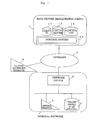
- Fig. 1 is an overall structural view of a network system including an illegal access data handling apparatus according to the present invention.
- a reference numeral 1 denotes a data center of a management agent providing a service for taking countermeasures against an illegal access.
- a reference numeral 11 denotes a control system provided in the data center.
- a reference numeral 12 denotes a client database for storing client information.
- a reference numeral 13 denotes a decoy server for decoying an illegal accessor in order to obtain information of the illegal accessor.
- a reference numeral 14 denotes a knowledge base to be used for analyzing illegal access information of the illegal accessor.
- a reference numeral 2 denotes the Internet.
- a reference numeral 3 denotes a network device used by a service contractor of the service of taking countermeasures against an illegal access.
- a reference numeral 4 denotes a general terminal used by the service contractor.
- a reference numeral 5 denotes a target server to be attacked, which is owned by the service contractor and targeted by the illegal accessor.
- a reference numeral 6 denotes an illegal accessor's terminal.
- control system 11 and the decoy server 13 function as the illegal access data handling apparatus, and the network device 3 functions as an illegal access data detection device.
- the network device 3, the general terminal 4 and the target server to be attacked 5 belong to the same internal communication network.
- Fig. 2 shows a functional block diagram of the network device 3.
- the network device 3 is composed of a data collection/transmission section 31 for receiving and transmitting data, an identification information discrimination section 32 for discriminating between a general communication and a decoying packet (response packet) to the decoy server from the control system 11, an illegal access detection section 33 for detecting an illegal access packet, a packet capsulation section 34 for encapsulating the illegal access packet or log data to be transferred to the control system 11, and for decapsulating the response packet transmitted from the control system 11, and a log acquisition section 35 for recording data processed through the network device 3.
- a data collection/transmission section 31 for receiving and transmitting data
- an identification information discrimination section 32 for discriminating between a general communication and a decoying packet (response packet) to the decoy server from the control system 11
- an illegal access detection section 33 for detecting an illegal access packet
- a packet capsulation section 34 for encapsulating the illegal access packet or log data to be transferred to the control system 11, and for decapsulating the response packet transmitted from the control system
- Fig. 3 also shows a functional block diagram of the control system.
- the control system 11 is composed of data reception/transmission section 111 for receiving and transmitting data, a client collating section 112 for collating a packet received whether to be transferred from a contractor or not, a data type discrimination section 113 for discriminating the type of data received from the network device 3, a packet capsulation section 114 for decapsulating an encapsulated illegal access packet or an encapsulated log data transmitted from the network device 3 and for encapsulating a response packet (response data) to be transmitted to the network device 3, and an illegal data analysis section 115 for analyzing the log data or illegal access packet received.
- the data center 1 is also provided with the client database 12, the decoy server 13, and the knowledge base 14 for exchanging data with the control system 11.
- the decoy server 13 functions as a response data generation section for generating the response data (response packet) to the illegal access packet.
- Fig. 4 shows the structures of communication packets transmitted and received by the network device 3 and the control system 11.
- a packet P1 is the illegal access packet.
- the packet P1 is transmitted from the illegal accessor's terminal 6 and received by the network device 3.
- a packet P2 is an encapsulated packet of the packet P1 for transmitting illegal access packet information including identification information.
- the packet P2 is transmitted from the network device 3 to the control system 11.
- a packet P3 is an encapsulated response packet for transmitting response packet information including the identification information to the illegal accessor.
- the packet P3 is transmitted from the control system 11 to the network device 3.
- a packet 4 is a decapsulated packet of the packet P3, and is the response packet from the decoy server 13 pretending to be the response from the target server to be attacked 5.
- the packet P4 has the same information stored as the contents of the response by the target server to be attacked 5. Normally, the packet P4 is not allowed to be transmitted directly over the Internet, but if encapsulated as shown in the packet P3, allowed to be transmitted to the network device 3.
- Fig. 5 shows an operational flow for handling an illegal access made by an illegal accessor into an internal communication network.
- the illegal accessor's terminal 6 has transmitted the illegal access packet P1 so as to illegally access the server (the target server to be attacked) 5 provided within the network (the internal communication network) of a contractor (step 101).
- the network device 3 detects the illegal access packet P1.
- the network device 3 when detecting the illegal access packet P1, encapsulates the illegal access packet P1 (the illegal access packet information) to generate the packet P2, and transmits the packet P2 to the data center 1 (step 102). This allows the network device 3 to prevent the illegal access by the illegal access packet P1 to the target server to be attacked 5.
- control system 11 in the data center 1 receives the packet P2 from the network device 3, analyzes the packet P2 received, encapsulates the response packet P4 from the decoy server 13 pretending to be a response from the target server to be attacked 5 to generate the packet P3, and sends the packet P3 back to the network device 3 (step 103).
- the network device 3 receives the packet P3 from the control system 11, decapsulates the packet P3 received so as to extract the response packet P4, and transmits the response packet P4 to the illegal accessor's terminal 6 (step 104).
- the illegal accessor would believe that the response packet P4 should be a response from the target server to be attacked 5, and start to illegally access the decoy server 13.
- a communication between the illegal accessor's terminal 6 and the decoy server 13 is made each time through a procedure from step 101 to step 104.
- a log analysis performed in the decoy server 13 exposes the approach of an illegal access in more detail.
- Fig. 6 is a flow chart illustrating the processing of a communication packet in the network device 3.
- the network device 3 upon reception of a communication packet through the data collection/transmission section 31 (step 301), discriminates between the encapsulated response packet P3, which is from the control system 11, and only a relay packet based upon the identification information of the received packet in the identification information discrimination section 32 (step 302).
- the received packet is the encapsulated response packet P3
- the encapsulated response packet P3 is decapsulated in the packet capsulation section 34 (step 303), and then transmitted to the illegal accessor's terminal 6 as the response (step 306).
- the packet is examined in the illegal access detection section 33 whether it is the illegal access packet P1 or not (step 304).
- the illegal access packet P1 is encapsulated in the packet capsulation section 34 to have the packet P2, in order to transfer the illegal access packet P1 to the control system 11 (step 305).
- the encapsulated illegal access packet P2 is transmitted to the control system 11 through the data collection/transmission section 31 (step 306).
- the packet is judged to be a normal packet in the illegal access examination in step 304, then the packet is relayed directly to the destination from the data collection/transmission section 31 (step 306).
- Fig. 7 shows an operational flow in the control system 11 for handling a received packet from the network device 3 of a contractor.
- control system 11 upon reception of a communication packet through the data reception/transmission section 111, refers to the client database 12 and collates the communication packet to find whether to be transmitted from a contractor or not. A packet failing to succeed in this collation may be disposed as incorrect data or handled in another task of the control system (outside the scope of the present invention).
- the packet P2 received which is encapsulated by the network device 3, is decapsulated in the packet capsulation section 114.
- the illegal access packet P1 when decapsulated in the packet capsulation section 114, is passed to the illegal data analysis section 115.
- the illegal data analysis section 115 analyzes the illegal access packet P1 extracted by referring to the knowledge base 14. A result from this analysis is added to the knowledge base 14 as an example for reference in future analyses.
- the illegal data analysis section 115 notifies the decoy server 13 of an analysis result, and receives the response packet P4 from the decoy server 13.
- the response packet P4 has the same information as the information that would be provided in response to the illegal access packet P1 by the target server to be attacked 5 if the illegal access packet P1 was received by the target server to be attacked 5.
- the response packet P4 is a packet transmitted from the target server to be attacked 5 through the network device 3.
- the response packet P4 is encapsulated in the packet capsulation section 114 to be the packet P3.
- the packet P3 is transmitted to the network device 3 through the data reception/transmission section 111.
- the network device 3 decapsulates the packet P3, extracts the response packet P4, and transmits the response packet P4 extracted to the illegal accessor's terminal 6.
- the network device 3 does not handle within itself the illegal access packet detected by the network device 3 but transmits the illegal access packet to the control system 11, thereby obtaining the response packet and decoying the illegal accessor into the decoy server provided within the data center of the agent.
- an illegal access handling service independent of the network of a client may be achieved.
- the illegal access packet from the illegal accessor's terminal is transferred from the network device 3 to the data center 1.
- Another embodiment will be discussed in the case that the log information of the network device 3 is transferred to the data center 1 in order to detecting an illegal access packet in an earlier stage.
- Fig. 8 shows the operation of an overall network system in such a case.
- step 101 to step 104 are the same as those discussed in the first embodiment, therefore, step 105 and step 106 will be discussed in this embodiment.
- the network device 3 always records the information of access from outside by the log acquisition section 35 (Fig. 2).
- This log information (communication history information) is encapsulated and transmitted to the control system 11 as the packet P5 upon reception of an order from the control system 11 or by a regular trigger of the network device 3 itself (step 105).
- Fig. 9 shows the structure of the packet P5.
- the packet P5 is an encapsulated packet of the log information, which is used for transmitting the log information of the network device to the control system.
- the packet capsulation section 114 decapsulates the packet P5, and the illegal data analysis section 115 analyzes the log information.
- the control system 11 transmits new illegal access detection set information to the network device 3 in order to update set information in the illegal access detection section 33 in the network device 3 (step 106).
- the illegal access detection set information is such information as to inform the network device 3 of a packet suspected of an illegal access packet, and instruct the network device 3 to treat any packet transmitted thereafter from the terminal transmitting the packet suspected of an illegal access packet as an illegal access packet.
- the illegal access detection set information corresponds to illegal access data designation information.
- the illegal access detection set information is generated by the illegal data analysis section 115.
- any access by the transmitting source suspected of making an illegal access is determined to be an illegal access packet by the illegal access detection section 33 in the network device 3.
- the control center 11 when determining that an access log from the terminal 6 is illegal, transmits to the network device 3 the set information instructing to reject the access from the terminal 6.
- the network device 3 detects the access from the terminal 6 (step 101) as an illegal access packet, encapsulates the packet from the terminal 6 (P1: illegal access packet to form P2, and then transmits the encapsulated packet to the control system 11 (step 102).
- P1 illegal access packet to form P2
- the data type discrimination section 113 shown in Fig. 6 judges that the received packet from the network device 3 is not an encapsulated illegal access packet P2 but a log information packet P5 based upon the identification information included in the received data. Then, in the illegal data analysis section 115, the log information packet is analyzed.
- the illegal data analysis section 115 when detecting a packet suspected of an illegal access packet, generates new illegal access set detection information.
- the data reception/transmission section 111 transmits generated new illegal access set detection information to the network device 3.
- a centralized analysis is requested by transmitting the log information of the network device 3 to the control system 11, and as a result, the response packet is acquired, so that the illegal accessor is decoyed into the decoy server provided within the data center of the agent. For that reason, the illegal access handling service may be achieved independently of the client's network. In addition to that, avoiding the illegal access of a packet suspected of an illegal access, although it is not a direct attack, may contribute to an earlier detection of an illegal access.
- the transmitting packet is encapsulated and the contents of the transmitting data is discriminated based upon the identification information.
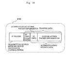
- Fig. 10 shows a packet P2H, which has authentication information added to the packet P2 as an example.
- the packet P2H has authentication information such as hash information which uses identification information and the following data as an input value, added in front of the identification information.
- the authentication information is added and checked in the network device 3 in the process of encapsulation/decapsulation by the packet capsulation section 34.
- the authentication information is added and checked in the control system 11 in the process of encapsulation/decapsulation by the packet capsulation section 114.
- adding the authentication information to a communication packet has a positive effect of improving communication security between the control system and the network device.
- the illegal access data handling apparatus according to the present invention has been discussed.
- a method for handling illegal access data according to the present invention may also be achieved by using the same procedures as those discussed in the previous embodiments.
- the system is to provide the network of a support contractor with a centralized network security control service for handling an illegal access to a computer network system.
- an illegal accessor is decoyed into the decoy server of the support provider.
- the network device of the service user when detecting an illegal access, attaches control information (encapsulation) to the illegal access packet, and then transfers the illegal access packet to the control system in the data center of the service provider.
- the data center is provided with the control system, the pseudo-server (referred to here as the decoy server), and the like.
- the decoy server is to decoy the illegal accessor by pretending to be the target server to be attacked of the service user, which is targeted by the illegal accessor, so that it sends back the same response as that of the target server to be attacked.
- the control system detaches the control information from the illegal access packet transmitted (decapsulation) and makes an analysis of the illegal access. In addition to that, the control system encapsulates a response from the decoy server, and transfers the response encapsulated to the network device.
- the network device upon reception of the response packet from the control center, decapsulates the response packet and then transmits the packet.
- the illegal accessor would believe that this response packet should be a response from the target server to be attacked, but in fact, is to communicate with the decoy server of the data center through the network device. Thus, the illegal accessor is to be decoyed into the decoy server.
- the system provides the network of a support contractor with the centralized network security control service for handling an illegal access to a computer network system.
- An item of the centralized control service is to decoy an illegal accessor into the decoy server of a support provider.
- the control system of the data center analyzes the log information, and when an illegal access is detected, the set information of the illegal access detection of the network device is updated.
Landscapes
- Engineering & Computer Science (AREA)
- Computer Security & Cryptography (AREA)
- Computer Hardware Design (AREA)
- Computing Systems (AREA)
- General Engineering & Computer Science (AREA)
- Computer Networks & Wireless Communication (AREA)
- Signal Processing (AREA)
- Data Exchanges In Wide-Area Networks (AREA)
Claims (10)
- Vorrichtung (1) zur Behandlung unerlaubter Zugriffsdaten, die außerhalb eines gegebenen internen Kommunikationsnetzwerkes (3, 4, 5) anzuordnen ist und ausgebildet ist, unerlaubte Zugriffsdaten (P1) zu empfangen, die von einer Datenkommunikationsvorrichtung (6) übertragen wurden, die außerhalb des internen Kommunikationsnetzwerks (3, 4, 5) angeordnet ist, für einen Zweck des unerlaubten Zugriffs zu dem internen Kommunikationsnetzwerk
dadurch gekennzeichnet, dass
die Vorrichtung (1) zur Behandlung unerlaubter Zugriffsdaten ausgebildet ist zum Empfangen der unerlaubten Zugriffsdaten (P1) von einer Erfassungsvorrichtung (3) für unerlaubte Zugriffsdaten, die zu dem internen Kommunikationsnetzwerk (3, 4, 5) und zum Ergreifen von Gegenmaßnahmen gegen die unerlaubten Zugriffsdaten durch Erzeugen von Antwortdaten (P4) auf die unerlaubten Zugriffsdaten (P1), welche Antwortdaten (P4) denselben Inhalt wie denjenigen von Antwortdaten haben, die von einer spezifischen Datenkommunikationsvorrichtung (5) erzeugt würden, die in dem internen Kommunikationsnetzwerk (3, 4, 5) angeordnet ist, als Antwort auf die unerlaubten Zugriffsdaten (P1), wenn die spezifische Datenkommunikationsvorrichtung (5) die unerlaubten Zugriffsdaten (P1) empfangen hätte. - Vorrichtung (1) zur Behandlung unerlaubter Zugriffsdaten nach Anspruch 1, bei der die Vorrichtung (1) zur Behandlung unerlaubter Zugriffsdaten mit der Erfassungsvorrichtung für unerlaubte Zugriffsdaten verbindbar ist für die Weiterleitung einer Datenkommunikation zwischen der Datenkommunikationsvorrichtung, die innerhalb des internen Kommunikationsnetzwerks angeordnet ist, und der Datenkommunikationsvorrichtung, die außerhalb des internen Kommunikationsnetzwerks (3, 4, 5) angeordnet ist, und für die Erfassung (33) der unerlaubten Zugriffsdaten (P1), und
bei der die Vorrichtung (1) zur Behandlung unerlaubter Zugriffsdaten ausgebildet ist zum Empfangen (102) der unerlaubten Zugriffsdaten (P1) von der Erfassungsvorrichtung (3) für unerlaubte Zugriffsdaten. - Vorrichtung (1) zur Behandlung unerlaubter Zugriffsdaten nach Anspruch 1 oder Anspruch 2, welche aufweist:einen Datenempfangsabschnitt (111) zum Empfangen der unerlaubten Zugriffsdaten (P1) von der Erfassungsvorrichtung (3) für unerlaubte Zugriffsdaten;einen Datenanalyseabschnitt (14, 115) zum Analysieren der unerlaubten Zugriffsdaten (P1), die von dem Datenempfangsabschnitt (111) empfangen wurden;einen Antwortdaten-Erzeugungsabschnitt (13) zum Erzeugen von Antwortdaten (P4) auf die unerlaubten Zugriffsdaten (P1) auf der Grundlage eines Analyseergebnisses von dem Datenanalyseabschnitt (115) ; undeinen Datenübertragungsabschnitt (111) zum Übertragen der von dem Antwortdaten-Erzeugungsabschnitt (13) erzeugten Antwortdaten (P4) zu der Erfassungsvorrichtung (3) für unerlaubte Zugriffsdaten.
- Vorrichtung (1) zur Behandlung unerlaubter Zugriffsdaten nach Anspruch 3, bei der der Datenempfangsabschnitt (111) ausgebildet ist zum Empfangen von gekapselten unerlaubten Zugriffsdaten (P2), die durch die Erfassungsvorrichtung (3) für unerlaubte Zugriffsdaten gekapselt (34) wurden, von der Erfassungsvorrichtung (3) für illegale Zugriffsdaten, wobei die Vorrichtung(1) zur Behandlung unerlaubter Zugriffsdaten weiterhin einen Kapselungsabschnitt (114) enthält für die Entkapselung der gekapselten unerlaubten Zugriffsdaten (P2), die von dem Datenempfangsabschnitt empfangen wurden, um die unerlaubten Zugriffsdaten (P1) herauszuziehen, und zum Kapseln der Antwortdaten (P4), und wobei der Datenübertragungsabschnitt (111) ausgebildet ist zum Übertragen der durch den Kapselungsabschnitt gekapselten Antwortdaten (P3) zu der Erfassungsvorrichtung für unerlaubte Zugriffsdaten.
- Vorrichtung zur Behandlung unerlaubter Zugriffsdaten nach Anspruch 3, bei der der Datenempfangsabschnitt (111) ausgebildet ist zum Empfangen von Kommunikationshistorieinformationen (P5) von der Erfassungsvorrichtung (3) für unerlaubte Zugriffsdaten, die eine Kommunikationshistorie der Erfassungsvorrichtung (3) für unerlaubte Zugriffsdaten anzeigen,
bei der der Datenanalyseabschnitt (14, 115) ausgebildet ist zum Analysieren der von dem Datenempfangsabschnitt (111) empfangenen Kommunikationshistorieinformationen (P5) und zum Erzeugen von Bezeichnungsinformationen für unerlaubte Zugriffsdaten, die von einer gegebenen Datenkommunikationsvorrichtung, die außerhalb des internen Kommunikationsnetzwerks (3, 4, 5) angeordnet ist, übertragene Daten als die unerlaubten Zugriffsdaten bezeichnen auf der Grundlage eines Analyseergebnisses der Kommunikationshistorieinformationen (P5), und bei der der Datenübertragungsabschnitt ausgebildet ist zum Übertragen (106) der von dem Datenanalyseabschnitt (14, 115) erzeugten Bezeichnungsinformationen für unerlaubte Zugriffsdaten zu der Erfassungsvorrichtung (3) für unerlaubte Zugriffsdaten. - Vorrichtung zur Behandlung unerlaubter Zugriffsdaten nach Anspruch 4, bei der der Datenempfangsabschnitt (111) ausgebildet ist zum Empfangen unerlaubter Zugriffsdaten mit an diese angefügten Authentifikationsinformationen, bei der die Authentifikationsinformationen in der Erfassungsvorrichtung (3) für unerlaubte Zugriffsdaten hinzugefügt sind und für eine Datenauthentifikation von der Erfassungsvorrichtung (3) für unerlaubte Zugriffsdaten verwendet sind, und bei der der Kapselungsabschnitt (114) ausgebildet ist zum Durchführen der Datenauthentifikation für die unerlaubten Zugriffsdaten durch Verwendung der Authentifikationsinformationen.
- Vorrichtung zur Behandlung unerlaubter Zugriffsdaten nach Anspruch 6, bei der der Kapselungsabschnitt (114) ausgebildet ist zum Anfügen der für die Datenauthentifikation zu verwendenden Authentifikationsinformationen an die Antwortdaten, und
bei der der Datenübertragungsabschnitt (111) ausgebildet ist zum Übertragen der Antwortdaten mit den durch den Kapselungsabschnitt (114) angefügten Authentifikationsinformationen zu der Erfassungsvorrichtung (3) für unerlaubte Zugriffsdaten. - Verfahren zur Behandlung unerlaubter Zugriffsdaten (P1) außerhalb eines gegebenen internen Kommunikationsnetzwerks (3, 4, 5), welches Verfahren aufweist:Empfangen unerlaubter Zugriffsdaten (P1), die von einer Datenkommunikationsvorrichtung (6), die außerhalb des internen Kommunikationsnetzwerks (3, 4, 5) angeordnet ist, übertragen wurden für einen Zweck des unerlaubten Zugriffs zu dem internen Kommunikationsnetzwerk (3, 4, 5),dadurch gekennzeichnet, dass
die unerlaubten Zugriffsdaten (P1) durch eine Vorrichtung (1) zur Behandlung unerlaubter Zugriffsdaten, die außerhalb des internen Kommunikationsnetzwerks angeordnet ist, von einer Erfassungsvorrichtung (3) für unerlaubte Zugriffsdaten, die zu dem internen Kommunikationsnetzwerk (3, 4, 5) gehört, empfangen werden; und dass Gegenmaßnahmen gegen die empfangenen unerlaubten Zugriffsdaten (P1) in der Vorrichtung (1) zur Behandlung unerlaubter Zugriffsdaten ergriffen werden durch Erzeugen von Antwortdaten (P4) auf die unerlaubten Zugriffsdaten (P1), welche Antwortdaten (P4) denselben Inhalt wie den von Antwortdaten haben, die durch eine in dem internen Kommunikationsnetzwerk (3, 4, 5) angeordnete spezifische Datenkommunikationsvorrichtung (5) erzeugt würden als Antwort auf die unerlaubten Zugriffsdaten (P1), wenn die spezifische Datenkommunikationsvorrichtung (5) die unerlaubten Zugriffsdaten (P1) empfangen hätte. - Verfahren nach Anspruch 8, bei dem die Vorrichtung (1) zur Behandlung unerlaubter Zugriffsdaten mit der Erfassungsvorrichtung (3) für unerlaubte Zugriffsdaten verbunden ist für die Weiterleitung einer Datenkommunikation zwischen der innerhalb des internen Kommunikationsnetzwerks (3, 4, 5) angeordneten Datenkommunikationsvorrichtung und der außerhalb des internen Kommunikationsnetzwerks (3, 4, 5) angeordneten Datenkommunikationsvorrichtung, und zum Erfassen (304) der unerlaubten Zugriffsdaten (P1); und bei der die unerlaubten Zugriffsdaten (P1) von der Erfassungsvorrichtung (3) für unerlaubte Zugriffsdaten empfangen (102) werden.
- Verfahren nach Anspruch 8 oder 9 welches aufweist:Empfangen (102, 111) der unerlaubten Zugriffsdaten (P1) von der Erfassungsvorrichtung (3) für unerlaubte Zugriffsdaten;Analysieren (14, 115) der durch das Empfangen empfangenen unerlaubten Zugriffsdaten (P1); Erzeugen (13) von Antwortdaten auf die unerlaubten Zugriffsdaten (P1) auf der Grundlage eines Analyseergebnisses des Analysierens; undÜbertragen (111) der durch die Erzeugung erzeugten Antwortdaten zur der Erfassungsvorrichtung (3) für unerlaubte Zugriffsdaten.
Applications Claiming Priority (2)
| Application Number | Priority Date | Filing Date | Title |
|---|---|---|---|
| JP2001036436 | 2001-02-14 | ||
| JP2001036436 | 2001-02-14 |
Publications (3)
| Publication Number | Publication Date |
|---|---|
| EP1244264A2 EP1244264A2 (de) | 2002-09-25 |
| EP1244264A3 EP1244264A3 (de) | 2004-07-28 |
| EP1244264B1 true EP1244264B1 (de) | 2006-06-28 |
Family
ID=18899709
Family Applications (1)
| Application Number | Title | Priority Date | Filing Date |
|---|---|---|---|
| EP01125045A Expired - Lifetime EP1244264B1 (de) | 2001-02-14 | 2001-10-22 | Verfahren und Vorrichtung zur Behandlung von unerlaubten Zugriffsdaten |
Country Status (4)
| Country | Link |
|---|---|
| US (1) | US7360250B2 (de) |
| EP (1) | EP1244264B1 (de) |
| CA (1) | CA2360147A1 (de) |
| DE (1) | DE60121133T2 (de) |
Families Citing this family (19)
| Publication number | Priority date | Publication date | Assignee | Title |
|---|---|---|---|---|
| US8087083B1 (en) * | 2002-01-04 | 2011-12-27 | Verizon Laboratories Inc. | Systems and methods for detecting a network sniffer |
| US7068999B2 (en) * | 2002-08-02 | 2006-06-27 | Symbol Technologies, Inc. | System and method for detection of a rogue wireless access point in a wireless communication network |
| US20040078592A1 (en) * | 2002-10-16 | 2004-04-22 | At & T Corp. | System and method for deploying honeypot systems in a network |
| US7698738B2 (en) * | 2003-05-14 | 2010-04-13 | Northrop Grumman Systems Corporation | System and method for real-time network-based recovery following an information warfare attack |
| EP1748342A1 (de) * | 2005-07-29 | 2007-01-31 | H+BEDV Datentechnik GmbH | Honigtopf Computersystem zum entdecken von Viren in einem Computernetzwerk |
| CN100454839C (zh) * | 2005-11-24 | 2009-01-21 | 华为技术有限公司 | 一种基于用户防攻击的装置以及方法 |
| JP4780413B2 (ja) * | 2007-01-12 | 2011-09-28 | 横河電機株式会社 | 不正アクセス情報収集システム |
| US8424098B2 (en) * | 2008-12-01 | 2013-04-16 | General Electric Company | System and method for enhanced data security |
| JP5326673B2 (ja) * | 2009-03-06 | 2013-10-30 | 富士通株式会社 | 制御回路、情報処理装置及び情報処理装置の制御方法 |
| US8949988B2 (en) * | 2010-02-26 | 2015-02-03 | Juniper Networks, Inc. | Methods for proactively securing a web application and apparatuses thereof |
| US8650215B2 (en) * | 2010-05-04 | 2014-02-11 | Red Hat, Inc. | Decoy application servers |
| US9485276B2 (en) | 2012-09-28 | 2016-11-01 | Juniper Networks, Inc. | Dynamic service handling using a honeypot |
| US9152808B1 (en) * | 2013-03-25 | 2015-10-06 | Amazon Technologies, Inc. | Adapting decoy data present in a network |
| EP3041190B1 (de) * | 2014-12-30 | 2020-11-25 | Juniper Networks, Inc. | Dynamische diensthandhabung unter verwendung eines honigtopfes |
| US10855721B2 (en) | 2015-05-27 | 2020-12-01 | Nec Corporation | Security system, security method, and recording medium for storing program |
| US10728256B2 (en) | 2017-10-30 | 2020-07-28 | Bank Of America Corporation | Cross channel authentication elevation via logic repository |
| US10721246B2 (en) | 2017-10-30 | 2020-07-21 | Bank Of America Corporation | System for across rail silo system integration and logic repository |
| US10621341B2 (en) | 2017-10-30 | 2020-04-14 | Bank Of America Corporation | Cross platform user event record aggregation system |
| CN112242984B (zh) * | 2019-07-19 | 2023-05-30 | 伊姆西Ip控股有限责任公司 | 检测异常网络请求的方法、电子设备和计算机程序产品 |
Family Cites Families (19)
| Publication number | Priority date | Publication date | Assignee | Title |
|---|---|---|---|---|
| US5124984A (en) | 1990-08-07 | 1992-06-23 | Concord Communications, Inc. | Access controller for local area network |
| JPH066347A (ja) | 1992-06-23 | 1994-01-14 | Mitsubishi Electric Corp | セキュリティ管理システム |
| US5414833A (en) * | 1993-10-27 | 1995-05-09 | International Business Machines Corporation | Network security system and method using a parallel finite state machine adaptive active monitor and responder |
| JP3688830B2 (ja) | 1995-11-30 | 2005-08-31 | 株式会社東芝 | パケット転送方法及びパケット処理装置 |
| JPH09214543A (ja) | 1996-02-05 | 1997-08-15 | Toshiba Corp | 通信経路制御方法および通信経路制御装置 |
| IL126149A (en) * | 1997-09-09 | 2003-07-31 | Sanctum Ltd | Method and system for protecting operations of trusted internal networks |
| JP2000047987A (ja) | 1998-07-30 | 2000-02-18 | Fuji Photo Film Co Ltd | データ出力方法および装置並びに記録媒体 |
| JP3648520B2 (ja) | 1998-09-11 | 2005-05-18 | 剛 石井 | ネットワーク通信の監視・制御方法及びこれを利用した監視・制御装置並びにネットワーク通信の監視・制御プログラムを記録したコンピュータ読み取り可能な記録媒体 |
| JP3618245B2 (ja) | 1999-03-09 | 2005-02-09 | 株式会社日立製作所 | ネットワーク監視システム |
| US6678827B1 (en) * | 1999-05-06 | 2004-01-13 | Watchguard Technologies, Inc. | Managing multiple network security devices from a manager device |
| WO2000072171A1 (en) * | 1999-05-24 | 2000-11-30 | Gregory Perry | Method and apparatus for remotely managed local network interface security |
| US6826697B1 (en) * | 1999-08-30 | 2004-11-30 | Symantec Corporation | System and method for detecting buffer overflow attacks |
| US6687833B1 (en) * | 1999-09-24 | 2004-02-03 | Networks Associates, Inc. | System and method for providing a network host decoy using a pseudo network protocol stack implementation |
| US6990591B1 (en) * | 1999-11-18 | 2006-01-24 | Secureworks, Inc. | Method and system for remotely configuring and monitoring a communication device |
| US6363489B1 (en) * | 1999-11-29 | 2002-03-26 | Forescout Technologies Inc. | Method for automatic intrusion detection and deflection in a network |
| US6880090B1 (en) * | 2000-04-17 | 2005-04-12 | Charles Byron Alexander Shawcross | Method and system for protection of internet sites against denial of service attacks through use of an IP multicast address hopping technique |
| AU2001281401A1 (en) * | 2000-08-18 | 2002-03-04 | Invicta Networks, Inc. | Systems and methods for distributed network protection |
| GB0022485D0 (en) * | 2000-09-13 | 2000-11-01 | Apl Financial Services Oversea | Monitoring network activity |
| US20030051026A1 (en) * | 2001-01-19 | 2003-03-13 | Carter Ernst B. | Network surveillance and security system |
-
2001
- 2001-10-22 DE DE60121133T patent/DE60121133T2/de not_active Expired - Fee Related
- 2001-10-22 EP EP01125045A patent/EP1244264B1/de not_active Expired - Lifetime
- 2001-10-25 CA CA002360147A patent/CA2360147A1/en not_active Abandoned
- 2001-11-26 US US09/991,932 patent/US7360250B2/en not_active Expired - Fee Related
Also Published As
| Publication number | Publication date |
|---|---|
| EP1244264A2 (de) | 2002-09-25 |
| CA2360147A1 (en) | 2002-08-14 |
| DE60121133T2 (de) | 2007-02-01 |
| EP1244264A3 (de) | 2004-07-28 |
| US7360250B2 (en) | 2008-04-15 |
| US20020112190A1 (en) | 2002-08-15 |
| DE60121133D1 (de) | 2006-08-10 |
Similar Documents
| Publication | Publication Date | Title |
|---|---|---|
| EP1244264B1 (de) | Verfahren und Vorrichtung zur Behandlung von unerlaubten Zugriffsdaten | |
| US20140109230A1 (en) | Real-time vulnerability monitoring | |
| EP1379046B1 (de) | Persönlicher Firewall mit Positionsdetektion | |
| EP1313290B1 (de) | Persönlicher Firewall mit Platzabhängiger Funktionalität | |
| US20240073233A1 (en) | System and method for providing security to in-vehicle network | |
| US6970917B1 (en) | System and method for remote control and management of wireless devices | |
| CN107005565A (zh) | 用于自动装置检测、装置管理及远程协助的系统及方法 | |
| CN101855864A (zh) | 用于给资源受限装置部署无线网络入侵检测系统的设备和方法 | |
| JP3618245B2 (ja) | ネットワーク監視システム | |
| MXPA05002559A (es) | Sistema y metodo para monitorear redes inalambricas de forma remota. | |
| US20050005162A1 (en) | Automated staged patch and policy management | |
| CN101299760B (zh) | 信息安全处理方法与信息安全处理系统、通信设备 | |
| US20070112941A2 (en) | Client capture of vulnerability data | |
| KR101088084B1 (ko) | 전자상거래 불법 침입 감시 및 차단 방법과 시스템 | |
| JP3495030B2 (ja) | 不正侵入データ対策処理装置、不正侵入データ対策処理方法及び不正侵入データ対策処理システム | |
| US7131142B1 (en) | Intelligent agents used to provide agent community security | |
| KR100860607B1 (ko) | 네트워크 통합보안 스위치장치 및 방법 | |
| CA3122328A1 (en) | A system for, and a method of creating cybersecurity situational awareness, threat detection and risk detection within the internet-of-things space | |
| KR101288103B1 (ko) | 전자상거래 불법 거래 탐지 및 차단 방법과 시스템 | |
| KR100439174B1 (ko) | 라돈-씨큐리티 게이트웨이 시스템의 정책 전달 및 경보용데이터베이스 관리방법 | |
| KR100474155B1 (ko) | 네트워크의 취약성 분석 시스템 및 방법 | |
| CN113612753A (zh) | 数据的远程引导系统及方法 | |
| KR20020096194A (ko) | 통합보안 네트워크 카드에 의한 네트워크 보안 방법 및시스템 | |
| CN117220752A (zh) | 一种星地数传链路安全传输系统及方法 | |
| WO2003063449A1 (en) | System and method for monitoring network security |
Legal Events
| Date | Code | Title | Description |
|---|---|---|---|
| PUAI | Public reference made under article 153(3) epc to a published international application that has entered the european phase |
Free format text: ORIGINAL CODE: 0009012 |
|
| AK | Designated contracting states |
Kind code of ref document: A2 Designated state(s): AT BE CH CY DE DK ES FI FR GB GR IE IT LI LU MC NL PT SE TR |
|
| AX | Request for extension of the european patent |
Free format text: AL;LT;LV;MK;RO;SI |
|
| PUAL | Search report despatched |
Free format text: ORIGINAL CODE: 0009013 |
|
| AK | Designated contracting states |
Kind code of ref document: A3 Designated state(s): AT BE CH CY DE DK ES FI FR GB GR IE IT LI LU MC NL PT SE TR |
|
| AX | Request for extension of the european patent |
Extension state: AL LT LV MK RO SI |
|
| 17P | Request for examination filed |
Effective date: 20040804 |
|
| AKX | Designation fees paid |
Designated state(s): DE FR GB |
|
| 17Q | First examination report despatched |
Effective date: 20050428 |
|
| GRAP | Despatch of communication of intention to grant a patent |
Free format text: ORIGINAL CODE: EPIDOSNIGR1 |
|
| RAP1 | Party data changed (applicant data changed or rights of an application transferred) |
Owner name: MITSUBISHI DENKI KABUSHIKI KAISHA |
|
| GRAS | Grant fee paid |
Free format text: ORIGINAL CODE: EPIDOSNIGR3 |
|
| GRAA | (expected) grant |
Free format text: ORIGINAL CODE: 0009210 |
|
| AK | Designated contracting states |
Kind code of ref document: B1 Designated state(s): DE FR GB |
|
| REG | Reference to a national code |
Ref country code: GB Ref legal event code: FG4D |
|
| REF | Corresponds to: |
Ref document number: 60121133 Country of ref document: DE Date of ref document: 20060810 Kind code of ref document: P |
|
| ET | Fr: translation filed | ||
| PG25 | Lapsed in a contracting state [announced via postgrant information from national office to epo] |
Ref country code: DE Free format text: LAPSE BECAUSE OF NON-PAYMENT OF DUE FEES Effective date: 20070501 |
|
| PLBE | No opposition filed within time limit |
Free format text: ORIGINAL CODE: 0009261 |
|
| STAA | Information on the status of an ep patent application or granted ep patent |
Free format text: STATUS: NO OPPOSITION FILED WITHIN TIME LIMIT |
|
| 26N | No opposition filed |
Effective date: 20070329 |
|
| GBPC | Gb: european patent ceased through non-payment of renewal fee |
Effective date: 20061022 |
|
| REG | Reference to a national code |
Ref country code: FR Ref legal event code: ST Effective date: 20070629 |
|
| PG25 | Lapsed in a contracting state [announced via postgrant information from national office to epo] |
Ref country code: GB Free format text: LAPSE BECAUSE OF NON-PAYMENT OF DUE FEES Effective date: 20061022 |
|
| PG25 | Lapsed in a contracting state [announced via postgrant information from national office to epo] |
Ref country code: FR Free format text: LAPSE BECAUSE OF NON-PAYMENT OF DUE FEES Effective date: 20061031 |