EP1244060A2 - Computer-aided product design system - Google Patents
Computer-aided product design system Download PDFInfo
- Publication number
- EP1244060A2 EP1244060A2 EP02006412A EP02006412A EP1244060A2 EP 1244060 A2 EP1244060 A2 EP 1244060A2 EP 02006412 A EP02006412 A EP 02006412A EP 02006412 A EP02006412 A EP 02006412A EP 1244060 A2 EP1244060 A2 EP 1244060A2
- Authority
- EP
- European Patent Office
- Prior art keywords
- product
- draft
- fillet
- release
- design
- Prior art date
- Legal status (The legal status is an assumption and is not a legal conclusion. Google has not performed a legal analysis and makes no representation as to the accuracy of the status listed.)
- Withdrawn
Links
Images








Classifications
-
- G—PHYSICS
- G06—COMPUTING OR CALCULATING; COUNTING
- G06T—IMAGE DATA PROCESSING OR GENERATION, IN GENERAL
- G06T17/00—Three-dimensional [3D] modelling for computer graphics
- G06T17/10—Constructive solid geometry [CSG] using solid primitives, e.g. cylinders, cubes
-
- G—PHYSICS
- G06—COMPUTING OR CALCULATING; COUNTING
- G06T—IMAGE DATA PROCESSING OR GENERATION, IN GENERAL
- G06T19/00—Manipulating three-dimensional [3D] models or images for computer graphics
- G06T19/20—Editing of three-dimensional [3D] images, e.g. changing shapes or colours, aligning objects or positioning parts
-
- G—PHYSICS
- G06—COMPUTING OR CALCULATING; COUNTING
- G06T—IMAGE DATA PROCESSING OR GENERATION, IN GENERAL
- G06T2219/00—Indexing scheme for manipulating 3D models or images for computer graphics
- G06T2219/20—Indexing scheme for editing of 3D models
- G06T2219/2021—Shape modification
Definitions
- This invention relates to a computer-aided product design system, more specifically, a product design system constituted as the so-called CAD (computer-aided design)/CAM (computer-aided manufacturing), CIM (computer-integrated manufacturing) and other product design systems.
- CAD computer-aided design
- CAM computer-aided manufacturing
- CIM computer-integrated manufacturing
- CAD/CAM computer numerical control
- the designer when molds are used to manufacture products, the designer normally uses a CAD system to first make or design a product model or product shape and the product model is then used to make or design a mold model in the mold design process. Next, this mold model is used to make mold fabrication data, after which the mold is fabricated by CNC (computer numerical control) fabrication, etc., using the data, and the fabricated mold is used to make the product by casting or cutting.
- CNC computer numerical control
- the shape of the product model constructed in the product design process determines the shape of the product, and therefore the release draft, i.e., the release draft for releasing the product from the mold required for the casting process, must be added to the product model in the product design process.
- a rounded portion referred to as a fillet is applied or formed on a square edge in this product model.
- the product model is edited such that portions where two lines or curves intersect continue smoothly with a circular arc (fillet) having designated or specified radius of curvature.
- the release draft is formed in the product model, and the fillet is applied or formed.
- the shape of the model is described, by using an edge often referred to as a winged edge, and by defining the relationship of the edge containing its left and right surfaces and points. If a fillet is applied, the edge disappears. For that reason, the fillet is formed at a relatively later stage.
- the fillet is added with the intent of improving appearance and in addition to avoiding the concentration of stress in the product (and mold).
- the fillet be applied in the initial stage of the product design process such that he can do the work while confirming or verifying the function of the product based on the product model or product shape with the fillet applied.
- a release draft when a product is given a complex shape with continuous uneven portions such as in the transmission case of a vehicle, a release draft must be formed or applied to each uneven portion and judgment must be made as to whether the formed release draft is sufficient to release the product from the mold, after which the operation of applying fillet must be performed. In this case, if the formed release draft is to be changed for some reason, the uneven portions must first be corrected, after which the release draft is corrected, resulting in a tedious operation.
- an object of this invention is to resolve the problems described above by providing a computer-aided product design system that allows the engineer (designer) to apply the fillet in an initial design stage prior to form the release draft in the product design process such that he can do the work while confirming and verifying the function of the part based on the product model or product shape with the fillet added.
- a second object of this invention is to provide a computer-aided product design system that makes operation relatively easy when it becomes necessary to change the release draft that has already been applied.
- a third object of this invention is to provide a computer-aided product design system that allows the engineer to apply the fillet or the release draft at a partial area of uneven portions in a simple manner.
- the invention provides a system for designing a product having at least a computer, a display connected to the computer for displaying result of processing of the computer, an input device connected to the computer for allowing an engineer to enter data in accordance with a required specification of the product and an interactive program, stored in the computer, for aiding the engineer to design the product through the display and the input device, the program having a shape modelling function realized by 3-dimensional curves and surfaces and including at least: product design process for allowing the engineer to design a product model by modelling the product through the shape modelling function; and mold design process for allowing the engineer to design a mold for producing the product based on the designed product model; wherein the program of the product design process comprising; basic element constructing means for constructing a basic element that constitutes the product model; fillet applying means for applying a fillet on the constructed basic element; and release draft judging means for judging whether a release draft formed on the constructed basic element with the applied fillet is sufficient for releasing the product from the mold to be designed on
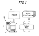
- FIG. 1 is a schematic diagram showing the overall configuration of a computer-aided product design system according to a first embodiment of the invention.
- reference numeral 10 indicates the product design system which comprises a computer 12, a display 14 connected to the computer 12 for displaying the result of processing and an interactive program 16 (stored in the computer 12) that realizes a shape modeling function by means of 3-dimensional curves and 3-dimensional surfaces via the output displayed on the display 14.
- the product design system 10 is equipped with a group of input devices including a keyboard, a mouse, etc., and generally assigned with reference numeral 18.
- the engineer enters data via the input device 18 based on a design specification that describes the required product (part) specification, whereby the product model is designed interactively by following the instructions stored in the program 16.
- the product is expressed in the program 16 as shape vertexes, edges, and other numerical data, and more specifically shape modeling of the product is expressed by means of solid model.
- the engineer sweeps basic shapes (primitives) such as cylinders displayed on the display 14 and conducts Boolean set operations comprising a sum set, a difference set and a product set to design a product model 20.
- the product design system is constituted as the CAD/CAM or CIM.
- FIG. 2 is an explanatory view for explaining the process from product design to mass-production performed using this product design system 10.
- CAD/CAM or CIM when a mold 24 is used to manufacture a product 26, the engineer normally uses this product design system 10 to make or design the product model 20 in the product design process, and the product model 20 is used to make or design a mold model 28 in the mold design process.
- the engineer uses the mold model 28 to prepare mold fabrication data which is then used to fabricate the mold 24 by means of an NC machining apparatus 30, etc., and the fabricated mold 24 is used to make the product 26 through casting or cutting (finishing).
- the system 10 has at least the computer 12, the display 14 connected to the computer for displaying result of processing of the computer, the input device 18 connected to the computer for allowing the engineer to enter data in accordance with the required specification of the product and the interactive program 16, stored in the computer, for aiding the engineer to design the product through the display and the input device, which has a shape modelling function realized by 3-dimensional curves and surfaces and including at least the product design process for allowing the engineer to design the product model 20 by modelling the product through the shape modelling function and the mold design process for allowing the engineer to design the mold 24 for producing the product based on the designed product model 20.
- the release draft to be required in the casting process i.e., the draft to be required to release the product 26 from the mold 24, must be formed or added to the product model in the product design process.
- FIG. 3 is an explanatory view showing the mold release. Material is flowed in the space prescribed by an upper part (core) 24a and a lower part (cavity) 24b of the mold 24 to make the target product 26. In order to make it easier to release the product 26 from the mold at this time, the release draft should thus be formed.
- FIG. 3 shows a simplified product, however, the product 26 is actually given a complex uneven shape like that shown in FIG. 4.
- the product is a transmission case of a vehicle. In this case the mold shape becomes complex and the number of mold release directions is increased.
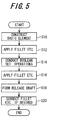
- FIG. 5 is a flow chart showing the operation of the computer-aided product design system 10 according to the embodiment of the invention.
- the basic element is construct or designed.
- “Basic element” refers, for example, to one or multiple uneven portions in the transmission case illustrated in FIG. 4, for example.
- the fillet, etc. is applied, i.e., filleting, smoothing, trimming, etc., are performed and in S14, the aforesaid Boolean set operations are conducted.
- the fillet, etc. is again applied to the calculated shape (basic element) and then in S18, the release draft is formed.
- the processing in S18 also includes the operation that judges whether or not the formed release draft is sufficient to release the product 26 (more accurately the product model 20).
- minimum correction of fillet, etc., for example, is performed as required.
- FIG. 17 is a flow chart showing the processing of the prior art.
- the release draft is formed after constructing the basic element, after which fillet, etc., is applied.
- this embodiment is configured such that the fillet, etc., is applied, first.
- FIG. 5 The processing in FIG. 5 is explained by referring to FIG. 6.
- a basic element (comprising a solid model) 100 of the product model 20 is constructed by combining two cylinders (primitives), and then a fillet 102 is applied or formed at a location where the surfaces mate on the side of the basic element 100.
- a release draft is formed on an area shown by the hatched portion and is assigned with reference numeral 104. Then it is judged whether the draft-formed surface 104 is sufficient, more precisely, the release draft on the surface 104 is sufficient for releasing the product from the mold model.
- the engineer need only designate or specify the location where the release draft is to be formed (specifically, where the release draft is to be formed, the direction in which the product is to be released and the angle of release draft) and the location where the judgment is to be performed, and the remainder of the processing is performed automatically by the computer 12 according to the instructions already described (programmed) in the program 16.
- the same is true when applying the fillet 102 in which the engineer need only designate or specify the location and the radius of curvature, after which the computer 12 conducts the filleting operation itself automatically.
- Boolean set operations are examples of Boolean set operations.
- this embodiment is configured such that the fillet 102, once applied, is temporarily removed when designating or specifying the location (where the release draft, etc., is to be formed and where the judgment is to be made).
- the program 16 is rewritten (reprogrammed) to execute such that the fillet is temporarily removed to allow the computer 12 to perform the necessary processing automatically.
- the fillet 102 is then temporarily removed to restore the edge 106, and the release draft is formed and judgement is made on the draft-formed surface 104 as to whether the draft is sufficient or not. For example, in FIG. 7, it is judged that the draft of the side (indicated by reference numeral 102c) is insufficient. After the formed release draft is judged to be sufficient, the fillet 102 is restored again.
- the engineer can do designing while confirming or verifying the function of the element 100 based on the product model 20 to which fillet 102 has been applied. Further, this can make the release draft correction operations easier than that in the prior art.
- FIG. 8 is a flow chart showing the release draft correction operation in this embodiment
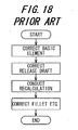
- FIG. 18 is a flow chart showing similar operation in the prior art.
- the release draft is removed in S100 as shown in FIG. 8, and then the release draft is formed newly in S102, thus simplifying the operation.
- one characteristic feature of the system in this embodiment is that it becomes possible to designate or specify a partial area of the element by the mold parting planes, etc.
- the program 16 is rewritten (reprogrammed) to allow designation or specification of a partial area of the element by the mold parting planes, etc.
- reference draft surface indicates a base point for the release draft and is a surface whose shape does not change after the release draft is formed.
- FIG. 10A, 10B and 10C are a set of partial cross-sectional views of the element 100.
- the reference draft surface can be set or designated at any location.
- FIG. 10A indicates the area where the draft is to be formed
- FIG. 10B and 10C illustrate draft-formed surfaces applied based on the set reference draft surface.
- the computer-aided product design system is configured such that the fillet 102, once applied, is temporarily removed to form the release draft and then the temporarily removed fillet 102 is again restored.
- the engineer can do the design while confirming or verifying the function of the product 26 based on the product model 20 with fillet 102 applied. Further, this can make the operation relatively easy even when the applied release draft is to be changed for some reason.
- this configuration also makes it possible to designate or specify a partial area of the element 100 by the mold parting plane and mold release direction of the mold 24 such that the release draft is formed in the designated area, in addition to the advantages mentioned above, the freedom of design can be improved.
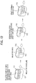
- FIG. 11 is a view, similar to a portion of FIG. 9, but showing the operation of the computer-aided product design system according to a second embodiment of the invention.
- the filleted surface (the surface on which the fillet 102 is applied) is ignored when the release draft is formed and the draft judgment is conducted on the draft-formed surface 104.
- the fillet 102 is applied automatically to the surface after the draft has been formed. The remainder of the configuration is the same as that of the first embodiment.
- the computer-aided product design system is configured such that the release draft is formed during which the fillet 102 is ignored and then the fillet 102 is again applied. With this, the engineer can do the design while confirming or verifying the function of the product 26 based on the product model 20 with fillet 102 applied. In addition, this can make the operation relatively easy even when the formed release draft is to be changed.
- FIG. 12 is a view, similar to a portion of FIG. 9, but showing the operation of the computer-aided product design system according to a third embodiment of the invention.
- the surface on which the fillet 102 has been applied can be selected as an area for formation of the release draft.
- the edge 106 has been disappeared or lost from the side surface, when the fillet-formed (filleted) surface is selected, the side surface including the fillet-applied surface around the element must be selected, as illustrated by the hatched portion in the figure.
- FIG. 13 is a view, similar to a portion of FIG. 9, but showing the operation of the computer-aided product design system according to a fourth embodiment of the invention.
- the surface on which fillet 102 has been applied can be selected as the reference draft surfaces.
- the program 16 is rewritten (reprogrammed) to allow the use of surfaces on which fillet 102 has been applied as the reference draft surface such that the computer 12 performs the processing automatically.
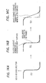
- FIG. 14A, 14B and 14C are a set of partial cross-sectional views of the element 100 which show the resulting draft surface formed tangentially continuous with the fillet 102. With this, it becomes possible to form the draft surface that is tangentially continuous with the fillet 102 automatically.
- the remainder of the configuration of the system in the fourth embodiment is the same as that of the first embodiment.
- the system according to the fourth embodiment can therefore enhance the freedom of design in addition to the advantages of the systems in the foregoing embodiments.
- FIG. 15 is a view, similar to a portion of FIG. 9, but showing the operation of system according to a fifth embodiment of the invention.
- the draft judgment can be conducted via the mold parting plane, mold release direction and the angle of release draft including the surface on which fillet 102 has been applied.
- the system according to the fifth embodiment is a modification of those of the third embodiment and the fourth embodiment and can therefore has the same advantages as those of the embodiments.
- the rest of the configuration is the same as that of the first embodiment.
- FIG. 16 is a view, similar to a portion of FIG. 9, but showing the operation of a system according to a sixth embodiment of the invention.
- the fillet 102 is a gradually-changing fillet with an indefinite radius of curvature.
- the program 16 is rewritten (reprogrammed) to allow the fillet 102 with a definite or constant radius of curvature as shown in the top left of the figure to be changed to the fillet 102 with an indefinite radius of curvature like that shown in the top right of the figure such that the computer 12 performs the processing automatically.
- the system according to the sixth embodiment is configured as described above, in addition to the advantages of the foregoing embodiments, it can automatically apply any fillet 102 whose radius of curvature is gradually changed as desired, whereby enabling to enhance the freedom of design.
- the first to sixth embodiments are thus configured to have a system (10) for designing a product (26) having at least a computer (12), a display (14) connected to the computer for displaying result of processing of the computer, an input device (18) connected to the computer for allowing an engineer to enter data in accordance with a required specification of the product and an interactive program (16), stored in the computer, for aiding the engineer to design the product through the display and the input device, the program having a shape modelling function realized by 3-dimensional curves and surfaces and including at least: product design process for allowing the engineer to design a product model (20) by modelling the product through the shape modelling function; and mold design process for allowing the engineer to design a mold (24) for producing the product based on the designed product model (20); wherein the program (16) of the product design process comprising; basic element constructing means (S10) for constructing a basic element (100) that constitutes the product model (20); fillet applying means (S12) for applying a fillet (102) on the constructed basic element; and release draft judging means (S
- the release draft judging means includes; release draft forming means (S18) for forming the release draft on the constructed basic element.
- the release draft forming means removes the fillet (102) during the release draft is being formed, and restores the fillet (102) after the release draft has been formed.
- the engineer can do the work while confirming or verifying the function of the product based on the product model with the fillet applied and in addition, the operation is relatively easy when the applied release draft is to be changed for some reason.
- the release draft forming means designates an area of the constructed basic element by a parting plane of the mold (24) and a direction of release of the product from the mold (24), and forms the release draft at the designated area.
- the release draft forming means forms the release draft an area other than a surface where the fillet (102) is applied, and applies the fillet at the area where the release draft has been formed when the formed release draft is sufficient for releasing the product from the mold.
- the engineer can do the work while confirming or verifying the function of the product based on the product model with the fillet applied and in addition, the operation is relatively easy when the applied release draft is to be changed for some reason.
- the release draft forming means determines the area and the surface as a reference draft surface, and forms the release draft based on the reference draft surface.
- the release draft forming means determines at least one of the area and the surface as a reference draft surface, and forms the release draft based on the reference draft surface.
- the fillet has a definite radius of curvature, or the fillet has an indefinite radius of curvature.
- a product design system having a computer and an interactive program stored in the computer for aiding the engineer to design a product and including product design process for allowing the engineer to design a product model and mold design process to design a mold for producing the product based on the designed product model
- the program is rewritten such that a basic element constituting the product model is construct (S10), a fillet, etc., is applied (S12), Boolean set operations are conducted (S16), and a release draft is formed (S18).
Landscapes
- Engineering & Computer Science (AREA)
- Physics & Mathematics (AREA)
- Geometry (AREA)
- Computer Graphics (AREA)
- Software Systems (AREA)
- General Physics & Mathematics (AREA)
- Theoretical Computer Science (AREA)
- Architecture (AREA)
- Computer Hardware Design (AREA)
- General Engineering & Computer Science (AREA)
- Moulds For Moulding Plastics Or The Like (AREA)
Abstract
Description
Claims (9)
- A system (10) for designing a product (26) having at least a computer (12), a display (14) connected to the computer for displaying result of processing of the computer, an input device (18) connected to the computer for allowing an engineer to enter data in accordance with a required specification of the product and an interactive program (16), stored in the computer, for aiding the engineer to design the product through the display and the input device, the program having a shape modelling function realized by 3-dimensional curves and surfaces and including at least:product design process for allowing the engineer to design a product model (20) by modelling the product through the shape modelling function; andmold design process for allowing the engineer to design a mold (24) for producing the product based on the designed product model (20);
CHARACTERIZED IN THAT:the program (16) of the product design process comprising;basic element constructing means (S10) for constructing a basic element (100) that constitutes the product model (20);fillet applying means (S12) for applying a fillet (102) on the constructed basic element;
andrelease draft judging means (S18) for judging whether a release draft formed on the constructed basic element with the applied fillet is sufficient for releasing the product (26) from the mold (24) to be designed on the mold design process. - A system according to claim 1, wherein the release draft judging means includes; release draft forming means (S18) for forming the release draft on the constructed basic element.
- A system according to claim 2, wherein the release draft forming means removes the fillet (102) during the release draft is being formed, and restores the fillet (102) after the release draft has been formed.
- A system according to claim 2, wherein the release draft forming means designates an area of the constructed basic element by a parting plane of the mold (24) and a direction of release of the product from the mold (24), and forms the release draft at the designated area.
- A system according to claim 4, wherein the release draft forming means forms the release draft an area other than a surface where the fillet (102) is applied, and applies the fillet at the area where the release draft has been formed when the formed release draft is sufficient for releasing the product from the mold.
- A system according to claim 4, wherein the release draft forming means determines the area and the surface as a reference draft surface, and forms the release draft based on the reference draft surface.
- A system according to claim 5, wherein the release draft forming means determines at least one of the area and the surface as a reference draft surface, and forms the release draft based on the reference draft surface.
- A system according to any of claims 1 to 7, wherein the fillet has a definite radius of curvature.
- A system according to any of claims 1 to 7, wherein the fillet has an indefinite radius of curvature.
Applications Claiming Priority (2)
| Application Number | Priority Date | Filing Date | Title |
|---|---|---|---|
| JP2001086221 | 2001-03-23 | ||
| JP2001086221 | 2001-03-23 |
Publications (2)
| Publication Number | Publication Date |
|---|---|
| EP1244060A2 true EP1244060A2 (en) | 2002-09-25 |
| EP1244060A3 EP1244060A3 (en) | 2004-10-27 |
Family
ID=18941637
Family Applications (1)
| Application Number | Title | Priority Date | Filing Date |
|---|---|---|---|
| EP02006412A Withdrawn EP1244060A3 (en) | 2001-03-23 | 2002-03-21 | Computer-aided product design system |
Country Status (2)
| Country | Link |
|---|---|
| US (1) | US7069094B2 (en) |
| EP (1) | EP1244060A3 (en) |
Families Citing this family (10)
| Publication number | Priority date | Publication date | Assignee | Title |
|---|---|---|---|---|
| US6874707B2 (en) | 2001-05-31 | 2005-04-05 | Terra Spase | System for automated monitoring and maintenance of crops including computer control of irrigation and chemical delivery using multiple channel conduit |
| US8066702B2 (en) * | 2005-01-11 | 2011-11-29 | Rittman Iii William J | Combination electrical stimulating and infusion medical device and method |
| US7945331B2 (en) * | 2005-01-11 | 2011-05-17 | Bradley D. Vilims | Combination electrical stimulating and infusion medical device and method |
| US20060155343A1 (en) * | 2005-01-11 | 2006-07-13 | Vilims Bradley D | Combination electrical stimulating and infusion medical device and method |
| US8454871B2 (en) * | 2005-07-21 | 2013-06-04 | Thomas R. Schrunk | Apparatus and method for producing light-responsive surfaces on opaque materials |
| US8525838B2 (en) * | 2008-02-08 | 2013-09-03 | Autodesk, Inc. | Associative fillet |
| US20120010860A1 (en) * | 2010-05-20 | 2012-01-12 | Kirkling Daniel R | System, method, and apparatus for engine installation integration |
| US9600793B2 (en) | 2013-12-09 | 2017-03-21 | International Business Machines Corporation | Active odor cancellation |
| CN112223695B (en) * | 2020-09-22 | 2022-04-29 | 珠海市英诚电子科技有限公司 | Method capable of quickly modifying pitched roof mechanism model |
| CN112861202A (en) * | 2021-02-19 | 2021-05-28 | 珠海格力精密模具有限公司 | Automatic die drawing method and system for part model |
Family Cites Families (4)
| Publication number | Priority date | Publication date | Assignee | Title |
|---|---|---|---|---|
| AU7736091A (en) * | 1990-09-14 | 1992-03-19 | Amsted Industries Incorporated | Improved rotary coupler assembly for railway vehicle |
| TW311113B (en) * | 1995-11-02 | 1997-07-21 | Fujitsu Ltd | |
| JPH09319772A (en) | 1996-05-30 | 1997-12-12 | Toyota Motor Corp | Product design system |
| JPH11300756A (en) * | 1998-04-21 | 1999-11-02 | Canon Inc | Mold part design apparatus and mold part design method |
-
2002
- 2002-03-21 EP EP02006412A patent/EP1244060A3/en not_active Withdrawn
- 2002-03-22 US US10/102,708 patent/US7069094B2/en not_active Expired - Fee Related
Also Published As
| Publication number | Publication date |
|---|---|
| US20020138238A1 (en) | 2002-09-26 |
| EP1244060A3 (en) | 2004-10-27 |
| US7069094B2 (en) | 2006-06-27 |
Similar Documents
| Publication | Publication Date | Title |
|---|---|---|
| EP1302904B1 (en) | Object modeling | |
| US7068268B2 (en) | Computer-aided product design system | |
| US5619625A (en) | Method for interpolating smooth free-form surfaces into curve mesh including composite curves | |
| US9569564B2 (en) | Automated cad process for creating mold packages | |
| JP4857012B2 (en) | Method for computer-aided design (CAD) of modeled objects having several faces | |
| US7069094B2 (en) | Computer-aided product design system | |
| JP5102332B2 (en) | Method for tool design | |
| JP2003533761A (en) | Methods for tool design | |
| JP3019398B2 (en) | Free-form surface machining data creation method | |
| CN112060292B (en) | Layout method of prefabricated concrete component molds for prefabricated buildings based on BIM | |
| JP2002373187A (en) | Computer aided product design equipment | |
| JP3019383B2 (en) | Roughing data creation method | |
| JP3727608B2 (en) | Method and system for industrializing parts | |
| EP0459251A1 (en) | Method for generating data defining tool path for rough machine | |
| JP2696914B2 (en) | Mold making method | |
| JPH0511828A (en) | Specifying method for fillet curved surface creation position | |
| JP4670600B2 (en) | Design support method | |
| JPH0641015B2 (en) | Three-dimensional solidification analysis method | |
| JP2701252B2 (en) | Object surface shape data creation method | |
| JP3019387B2 (en) | Roughing data creation method | |
| JP2767801B2 (en) | Object surface shape data creation method | |
| JP2737132B2 (en) | Object surface shape data creation method | |
| JP2707781B2 (en) | 3D shape processing method | |
| JP3187811B2 (en) | Object surface shape data creation method | |
| JP2932528B2 (en) | Object surface shape data creation method |
Legal Events
| Date | Code | Title | Description |
|---|---|---|---|
| PUAI | Public reference made under article 153(3) epc to a published international application that has entered the european phase |
Free format text: ORIGINAL CODE: 0009012 |
|
| 17P | Request for examination filed |
Effective date: 20020321 |
|
| AK | Designated contracting states |
Kind code of ref document: A2 Designated state(s): AT BE CH CY DE DK ES FI FR GB GR IE IT LI LU MC NL PT SE TR |
|
| AX | Request for extension of the european patent |
Free format text: AL;LT;LV;MK;RO;SI |
|
| PUAL | Search report despatched |
Free format text: ORIGINAL CODE: 0009013 |
|
| AK | Designated contracting states |
Kind code of ref document: A3 Designated state(s): AT BE CH CY DE DK ES FI FR GB GR IE IT LI LU MC NL PT SE TR |
|
| AX | Request for extension of the european patent |
Extension state: AL LT LV MK RO SI |
|
| AKX | Designation fees paid |
Designated state(s): DE FR GB |
|
| 17Q | First examination report despatched |
Effective date: 20070504 |
|
| STAA | Information on the status of an ep patent application or granted ep patent |
Free format text: STATUS: THE APPLICATION HAS BEEN WITHDRAWN |
|
| 18W | Application withdrawn |
Effective date: 20121214 |