EP1243850A1 - Combustion head for a fuel oil burner - Google Patents
Combustion head for a fuel oil burner Download PDFInfo
- Publication number
- EP1243850A1 EP1243850A1 EP01830192A EP01830192A EP1243850A1 EP 1243850 A1 EP1243850 A1 EP 1243850A1 EP 01830192 A EP01830192 A EP 01830192A EP 01830192 A EP01830192 A EP 01830192A EP 1243850 A1 EP1243850 A1 EP 1243850A1
- Authority
- EP
- European Patent Office
- Prior art keywords
- head
- flame
- air
- combustion
- recirculating
- Prior art date
- Legal status (The legal status is an assumption and is not a legal conclusion. Google has not performed a legal analysis and makes no representation as to the accuracy of the status listed.)
- Granted
Links
Images

Classifications
-
- F—MECHANICAL ENGINEERING; LIGHTING; HEATING; WEAPONS; BLASTING
- F23—COMBUSTION APPARATUS; COMBUSTION PROCESSES
- F23C—METHODS OR APPARATUS FOR COMBUSTION USING FLUID FUEL OR SOLID FUEL SUSPENDED IN A CARRIER GAS OR AIR
- F23C7/00—Combustion apparatus characterised by arrangements for air supply
- F23C7/008—Flow control devices
-
- F—MECHANICAL ENGINEERING; LIGHTING; HEATING; WEAPONS; BLASTING
- F23—COMBUSTION APPARATUS; COMBUSTION PROCESSES
- F23C—METHODS OR APPARATUS FOR COMBUSTION USING FLUID FUEL OR SOLID FUEL SUSPENDED IN A CARRIER GAS OR AIR
- F23C7/00—Combustion apparatus characterised by arrangements for air supply
- F23C7/002—Combustion apparatus characterised by arrangements for air supply the air being submitted to a rotary or spinning motion
- F23C7/004—Combustion apparatus characterised by arrangements for air supply the air being submitted to a rotary or spinning motion using vanes
-
- F—MECHANICAL ENGINEERING; LIGHTING; HEATING; WEAPONS; BLASTING
- F23—COMBUSTION APPARATUS; COMBUSTION PROCESSES
- F23C—METHODS OR APPARATUS FOR COMBUSTION USING FLUID FUEL OR SOLID FUEL SUSPENDED IN A CARRIER GAS OR AIR
- F23C9/00—Combustion apparatus characterised by arrangements for returning combustion products or flue gases to the combustion chamber
- F23C9/006—Combustion apparatus characterised by arrangements for returning combustion products or flue gases to the combustion chamber the recirculation taking place in the combustion chamber
-
- F—MECHANICAL ENGINEERING; LIGHTING; HEATING; WEAPONS; BLASTING
- F23—COMBUSTION APPARATUS; COMBUSTION PROCESSES
- F23D—BURNERS
- F23D11/00—Burners using a direct spraying action of liquid droplets or vaporised liquid into the combustion space
- F23D11/36—Details
- F23D11/40—Mixing tubes; Burner heads
- F23D11/404—Flame tubes
-
- F—MECHANICAL ENGINEERING; LIGHTING; HEATING; WEAPONS; BLASTING
- F23—COMBUSTION APPARATUS; COMBUSTION PROCESSES
- F23D—BURNERS
- F23D2207/00—Ignition devices associated with burner
-
- F—MECHANICAL ENGINEERING; LIGHTING; HEATING; WEAPONS; BLASTING
- F23—COMBUSTION APPARATUS; COMBUSTION PROCESSES
- F23D—BURNERS
- F23D2209/00—Safety arrangements
Definitions
- the present invention relates to a combustion head for atomized fuel oil burners, and which, according to the invention, produces a low-temperature flame.
- combustion of the combustible fluid and fluid combustion supporter mixture is brought about by means of a combustion head, which substantially comprises a tubular air conduit into which the fluid combustion supporter, e.g. air, is blown and mixes with the combustible fluid, in this case atomized oil, fed into the same tubular air conduit by means of a mixing device; and combustion is initiated by an ignition device igniting the fuel/combustion supporter mixture.
- a combustion head substantially comprises a tubular air conduit into which the fluid combustion supporter, e.g. air, is blown and mixes with the combustible fluid, in this case atomized oil, fed into the same tubular air conduit by means of a mixing device; and combustion is initiated by an ignition device igniting the fuel/combustion supporter mixture.
- the main object of the combustion head according to the present invention is to further improve conventional methods of reducing the nitric oxide content of combustion products.
- the combustion head according to the present invention therefore provides for an exothermic combustion reaction producing fumes with a very small nitric oxide content.
- the present invention relates to a combustion head for burners, and which provides for a low-temperature flame.
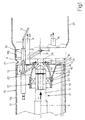
- the combustion head 10 shown in Figure 1 substantially comprises a tubular air conduit 11 into which the fluid combustion supporter, e.g. air, is fed by a blower (not shown) and mixes with a combustible fluid, e.g. atomized oil, fed into tubular air conduit 11 by a mixing device (see below). Downstream from the air-fuel mixing region, an ignition device 12 ignites the mixture to initiate combustion.
- the fluid combustion supporter e.g. air
- a blower not shown
- a combustible fluid e.g. atomized oil
- Combustion head 10 is fixed to a blower assembly (not shown) in turn fixed to the wall of a combustion chamber (not shown) by means of a connecting flange (not shown).
- tubular air conduit 11 Near the end inserted inside the combustion chamber, tubular air conduit 11 has a substantially disk-shaped flame deflector 13 positioned perpendicularly to the air flow direction, which, for the sake of simplicity, is parallel to a longitudinal axis of symmetry S, as shown by arrow F.
- the periphery of flame deflector 13 integral with tubular air conduit 11 is normally fitted with pipes 14 arranged symmetrically and which define the flow section for a certain amount of tertiary air A3 (see below).
- pipes 14 are four in number, though only two are shown in Figure 1.
- Pipes 14 are located downstream from flame deflector 13 in the direction of arrow F; the central portion of flame deflector 13 has a substantially circular central opening 15 symmetrical with respect to axis S; and a pipe 16 for the insertion of a flame detector (not shown) is fixed upstream from flame deflector 13.
- Tubular air conduit 11 houses a spray-holder 17 coaxial with axis S and which provides for feeding highpressure fuel to an oil nozzle 18 where the fuel is atomized.
- Spray-holder 17 is fitted concentrically with a propeller device 19 and an air nozzle 20 to form a unit 21, which, as will be seen, may be moved axially along axis S.
- Unit 21 is located upstream from flame deflector 13, which also provides for effectively protecting unit 21 from excessively high temperatures in the flame region.
- Unit 21, which, as stated, comprises spray-holder 17, propeller device 19 and air nozzle 20, is centered with respect to both tubular air conduit 11 and central opening 15 of flame deflector 13 by a support 22 comprising a locating sleeve 23 supporting air nozzle 20, and one or more wings 24 for fixing locating sleeve 23 to flame deflector 13.
- means 25 comprise a screw engaging an eye on flame deflector 13 to adjust the position of sleeve 23 with respect to flame deflector 13; and means 26 comprise a screw engaging a threaded hole on support 22.
- Means 25 and 26 therefore provide for adjusting the position of unit 21 with respect to central opening 15.
- the positions of propeller device 19 and spray-holder 17 with respect to air nozzle 20 determine the flow rate of primary air A1 at the outlet section of air nozzle 20.
- tubular air conduit 11 comprises a front portion 11a and a rear portion 11b, with an annular gap 27 in between for the recirculation of fumes R; and rear portion 11b is fixed firmly to front portion 11a by members 28, only one of which is shown in Figure 1.
- portion 11b of tubular air conduit 11 is fitted with a recirculating flame pipe 29, which is adjustable to narrow annular gap 27 for recirculating fumes R.
- combustion head 10 In actual use, to operate combustion head 10, a stream of combustion supporting air is fed by the blower (not shown) along tubular air conduit 11 to flame deflector 13, where it is divided into three distinct air sections A1, A2, A3 (primary, secondary and tertiary respectively) as explained above.
- propeller device 19 rotates the combustion supporting air to produce, at the outlet of air nozzle 20, a swirling air jet which mixes with the oil atomized by oil nozzle 18, and the characteristics of which are exploited to control the stability of the flame and combustion intensity.
- the converging shape of air nozzle 20 provides for effectively mixing the air and oil by concentrating the air jet in the spray from oil nozzle 18; and combustion of the air/atomized fuel mixture so formed is initiated by ignition device 12 to create, close to air nozzle 20, a reducing zone where combustion is incomplete.
- the flame produced in this zone is simultaneously confined by the combustion supporter issuing from secondary air section A2 at central opening 15 of flame deflector 13, the flow rate of which varies according to the adjustment of unit 21 - defined, as stated, by spray-holder 17, propeller device 19 and air nozzle 20 - with respect to central air opening 15 of flame deflector 13.
- the combustion process is also assisted by recirculating fumes R, which are drawn in through gap 27 for recirculating fumes R and defined by the position of recirculating flame pipe 29 with respect to tubular air conduit 11.
- the volume of recirculating fumes R drawn into recirculating flame pipe 29 through gap 27 depends on the speeds at which the combustion supporting air flows through the three distinct air sections A1, A2 and A3; which speeds create a low-pressure zone at annular gap 27 to assist intake of recirculating fumes R.
- the volume of recirculating fumes R may be said to depend on the speed and fluid-dynamic characteristics of the air divided into the three sections A1, A2, A3, and on the size of gap 27 between tubular air conduit 11 and recirculating flame pipe 29.
- the flow rate of recirculating fumes R through gap 27 can therefore be controlled by adjusting the position of recirculating flame pipe 29 along axis S. This provides for optimizing the intake volume of recirculating fumes R, the main function of which is to lower the flame temperature, which is mainly responsible for the formation of Nox.
- the position of recirculating flame pipe 29 with respect to tubular air conduit 11 is adjusted by adjusting a pin 30, integral with rear portion 11b of tubular air conduit 11, with respect to a sloping slot 31 formed in recirculating flame pipe 29.
- a pin 30, integral with rear portion 11b of tubular air conduit 11, with respect to a sloping slot 31 formed in recirculating flame pipe 29 the user, when the burner is off, need simply rotate pipe 29 about axis S with respect to tubular air conduit 11, so as to exploit the "screw effect" of pin 30 engaging sloping slot 31.
- the next combustion stage takes place at the oxidizing zone, where the combustion supporting air from tertiary air section A3, defined by pipes 14, completes the combustion process inside recirculating flame pipe 29.
- sleeve 23 and the elements connected to it are replaced by a flame deflector 13 comprising a given number of fins 13a, e.g. four fins 13a spaced 90° apart, for loosely centering air nozzle 20 and all the elements connected to it.
- Air nozzle 20 and all the elements connected to it are pressed in between fins 13a; and the quantity of secondary air A2 is adjusted by adjusting the position of air nozzle 20 with respect to central opening 15. Obviously, enough space is left between one fin 13a and another to allow secondary air A2 to reach opening 15.
- recirculating flame pipe 29 comprises two portions 29a, 29b connected integrally to each other.
- Portion 29b has a number of slots 32 perpendicular to axis S and which, as before, define an annular gap 27 for recirculating fumes R.
- pin 30 is integral with flame deflector 13, and sloping slot 31 is formed in portion 29b of recirculating flame pipe 29.
- the user when combustion head 10 is off, simply turns recirculating flame pipe 29 one way or the other about axis S to exploit the "screw effect" of pin 30 engaging sloping slot 31.
- ignition device 12 is advantageously fixed to the upstream face of flame deflector 13, to enable the user, when necessary, to remove ignition device 12 from the boiler side as opposed to the rear portion of combustion head 10.
Landscapes
- Engineering & Computer Science (AREA)
- Chemical & Material Sciences (AREA)
- Combustion & Propulsion (AREA)
- Mechanical Engineering (AREA)
- General Engineering & Computer Science (AREA)
- Pressure-Spray And Ultrasonic-Wave- Spray Burners (AREA)
- Spray-Type Burners (AREA)
- Nozzles For Spraying Of Liquid Fuel (AREA)
- Feeding And Controlling Fuel (AREA)
Abstract
- a tubular air conduit (11);
- a flame deflector (13) having a central opening (15) ;
- a spray-holder (17) having an oil nozzle (18) for atomizing the fuel oil;
- an air nozzle (20) concentric with the spray-holder (17); and
- an ignition device (12) for igniting a mixture of a combustion supporting fluid and atomized particles of the fuel oil;
Description
- The present invention relates to a combustion head for atomized fuel oil burners, and which, according to the invention, produces a low-temperature flame.
- In burners of the type referred to in the present invention, combustion of the combustible fluid and fluid combustion supporter mixture is brought about by means of a combustion head, which substantially comprises a tubular air conduit into which the fluid combustion supporter, e.g. air, is blown and mixes with the combustible fluid, in this case atomized oil, fed into the same tubular air conduit by means of a mixing device; and combustion is initiated by an ignition device igniting the fuel/combustion supporter mixture.
- As anyone skilled in the art knows, one of the major problems posed by combustion heads, in terms of ecological impact, is the emission into the atmosphere of nitric oxides Nox produced during the combustion process.
- The main object of the combustion head according to the present invention is to further improve conventional methods of reducing the nitric oxide content of combustion products.
- The combustion head according to the present invention therefore provides for an exothermic combustion reaction producing fumes with a very small nitric oxide content.
- It is a further object of the present invention to reduce the emission into the atmosphere of other polluting agents (carbon monoxide, unburned hydrocarbons, smoke, etc.).
- According to the present invention, there is provided a combustion head for burners, as claimed in Claim 1.
- A number of non-limiting embodiments of the present invention will be described by way of example with reference to the accompanying drawings, in which:
- Figure 1 shows a longitudinal section of a first embodiment of the combustion head according to the present invention;
- Figure 2 shows a longitudinal section of a second embodiment of the combustion head according to the present invention;
- Figure 3 shows a side view of the Figure 2 combustion head.
-
- As stated, the present invention relates to a combustion head for burners, and which provides for a low-temperature flame.
- The
combustion head 10 shown in Figure 1 substantially comprises atubular air conduit 11 into which the fluid combustion supporter, e.g. air, is fed by a blower (not shown) and mixes with a combustible fluid, e.g. atomized oil, fed intotubular air conduit 11 by a mixing device (see below). Downstream from the air-fuel mixing region, anignition device 12 ignites the mixture to initiate combustion. -
Combustion head 10 is fixed to a blower assembly (not shown) in turn fixed to the wall of a combustion chamber (not shown) by means of a connecting flange (not shown). - Near the end inserted inside the combustion chamber,
tubular air conduit 11 has a substantially disk-shaped flame deflector 13 positioned perpendicularly to the air flow direction, which, for the sake of simplicity, is parallel to a longitudinal axis of symmetry S, as shown by arrow F. The periphery offlame deflector 13 integral withtubular air conduit 11 is normally fitted withpipes 14 arranged symmetrically and which define the flow section for a certain amount of tertiary air A3 (see below). In the example described,pipes 14 are four in number, though only two are shown in Figure 1. -
Pipes 14 are located downstream fromflame deflector 13 in the direction of arrow F; the central portion offlame deflector 13 has a substantially circularcentral opening 15 symmetrical with respect to axis S; and apipe 16 for the insertion of a flame detector (not shown) is fixed upstream fromflame deflector 13. -
Tubular air conduit 11 houses a spray-holder 17 coaxial with axis S and which provides for feeding highpressure fuel to anoil nozzle 18 where the fuel is atomized. - Spray-
holder 17 is fitted concentrically with apropeller device 19 and anair nozzle 20 to form aunit 21, which, as will be seen, may be moved axially alongaxis S. Unit 21 is located upstream fromflame deflector 13, which also provides for effectively protectingunit 21 from excessively high temperatures in the flame region.Unit 21, which, as stated, comprises spray-holder 17,propeller device 19 andair nozzle 20, is centered with respect to bothtubular air conduit 11 andcentral opening 15 offlame deflector 13 by asupport 22 comprising a locatingsleeve 23 supportingair nozzle 20, and one ormore wings 24 for fixing locatingsleeve 23 toflame deflector 13. - The end of
air nozzle 20 facingflame deflector 13 converges slightly. - As shown in Figure 1, the position of
unit 21 with respect toflame deflector 13 can be adjusted, as will be seen, usingmeans - In the example shown, means 25 comprise a screw engaging an eye on
flame deflector 13 to adjust the position ofsleeve 23 with respect toflame deflector 13; and means 26 comprise a screw engaging a threaded hole onsupport 22. -
Means unit 21 with respect tocentral opening 15. - The positions of
propeller device 19 and spray-holder 17 with respect toair nozzle 20 determine the flow rate of primary air A1 at the outlet section ofair nozzle 20. - Whereas, as stated, adjusting the position of
air nozzle 20 with respect tocentral opening 15 offlame deflector 13, by movingunit 21 axially in the direction of arrowF using means - As shown in Figure 1,
tubular air conduit 11 comprises afront portion 11a and arear portion 11b, with anannular gap 27 in between for the recirculation of fumes R; andrear portion 11b is fixed firmly tofront portion 11a bymembers 28, only one of which is shown in Figure 1. - Downstream from
flame deflector 13,portion 11b oftubular air conduit 11 is fitted with a recirculatingflame pipe 29, which is adjustable to narrowannular gap 27 for recirculating fumes R. - In actual use, to operate
combustion head 10, a stream of combustion supporting air is fed by the blower (not shown) alongtubular air conduit 11 toflame deflector 13, where it is divided into three distinct air sections A1, A2, A3 (primary, secondary and tertiary respectively) as explained above. - In the primary air A1 section,
propeller device 19 rotates the combustion supporting air to produce, at the outlet ofair nozzle 20, a swirling air jet which mixes with the oil atomized byoil nozzle 18, and the characteristics of which are exploited to control the stability of the flame and combustion intensity. The converging shape ofair nozzle 20 provides for effectively mixing the air and oil by concentrating the air jet in the spray fromoil nozzle 18; and combustion of the air/atomized fuel mixture so formed is initiated byignition device 12 to create, close toair nozzle 20, a reducing zone where combustion is incomplete. - The flame produced in this zone is simultaneously confined by the combustion supporter issuing from secondary air section A2 at
central opening 15 offlame deflector 13, the flow rate of which varies according to the adjustment of unit 21 - defined, as stated, by spray-holder 17,propeller device 19 and air nozzle 20 - with respect tocentral air opening 15 offlame deflector 13. - At this stage, the combustion process is also assisted by recirculating fumes R, which are drawn in through
gap 27 for recirculating fumes R and defined by the position of recirculatingflame pipe 29 with respect totubular air conduit 11. The volume of recirculating fumes R drawn into recirculatingflame pipe 29 throughgap 27 depends on the speeds at which the combustion supporting air flows through the three distinct air sections A1, A2 and A3; which speeds create a low-pressure zone atannular gap 27 to assist intake of recirculating fumes R. - In short, the volume of recirculating fumes R may be said to depend on the speed and fluid-dynamic characteristics of the air divided into the three sections A1, A2, A3, and on the size of
gap 27 betweentubular air conduit 11 andrecirculating flame pipe 29. - The flow rate of recirculating fumes R through
gap 27 can therefore be controlled by adjusting the position of recirculatingflame pipe 29 along axis S. This provides for optimizing the intake volume of recirculating fumes R, the main function of which is to lower the flame temperature, which is mainly responsible for the formation of Nox. - The position of recirculating
flame pipe 29 with respect totubular air conduit 11 is adjusted by adjusting apin 30, integral withrear portion 11b oftubular air conduit 11, with respect to asloping slot 31 formed in recirculatingflame pipe 29. Obviously, to adjust the position of recirculatingflame pipe 29 with respect totubular air conduit 11, and so adjust the size ofannular gap 27 for recirculating fumes R, the user, when the burner is off, need simply rotatepipe 29 about axis S with respect totubular air conduit 11, so as to exploit the "screw effect" ofpin 30 engaging slopingslot 31. - The next combustion stage takes place at the oxidizing zone, where the combustion supporting air from tertiary air section A3, defined by
pipes 14, completes the combustion process inside recirculatingflame pipe 29. - In the second embodiment of the present invention shown in Figures 2 and 3,
sleeve 23 and the elements connected to it are replaced by aflame deflector 13 comprising a given number offins 13a, e.g. fourfins 13a spaced 90° apart, for loosely centeringair nozzle 20 and all the elements connected to it.Air nozzle 20 and all the elements connected to it are pressed in betweenfins 13a; and the quantity of secondary air A2 is adjusted by adjusting the position ofair nozzle 20 with respect tocentral opening 15. Obviously, enough space is left between onefin 13a and another to allow secondary air A2 to reachopening 15. - As regards primary and tertiary air A1 and A3, the same considerations apply as in the first embodiment in Figure 1.
- In the second embodiment shown in Figures 2 and 3, recirculating
flame pipe 29 comprises twoportions Portion 29b has a number ofslots 32 perpendicular to axis S and which, as before, define anannular gap 27 for recirculating fumes R. In this embodiment,pin 30 is integral withflame deflector 13, and slopingslot 31 is formed inportion 29b of recirculatingflame pipe 29. In this case, too, to adjust the amount of fumes R recirculated throughannular gap 27, the user, whencombustion head 10 is off, simply turns recirculatingflame pipe 29 one way or the other about axis S to exploit the "screw effect" ofpin 30 engaging slopingslot 31. - In the second embodiment shown in Figures 2 and 3,
ignition device 12 is advantageously fixed to the upstream face offlame deflector 13, to enable the user, when necessary, to removeignition device 12 from the boiler side as opposed to the rear portion ofcombustion head 10.
Claims (17)
- A combustion head (10) for a fuel oil burner, comprising:the combustion head (10) being characterized in that said air nozzle (20) is located upstream from said flame deflector (13) and at said central opening (15).a tubular air conduit (11) for supplying a combustion supporting fluid;a flame deflector (13) comprising a central opening (15), said flame deflector (13) being fixed to said tubular air conduit (11) and substantially perpendicular to the flow direction (F) of the combustion supporting fluid;a spray-holder (17) having an oil nozzle (18) for atomizing the fuel oil;an air nozzle (20) concentric with said spray-holder (17); andan ignition device (12) for igniting a mixture comprising the combustion supporting fluid and atomized particles of the fuel oil;
- A head (10) as claimed in Claim 1, wherein said air nozzle (20) is substantially conical.
- A head (10) as claimed in Claim 2, wherein the quantity of primary air (A1) required to initiate the combustion process is adjusted by adjusting the position of said spray-holder (17) with respect to said air nozzle (20).
- A head (10) as claimed in Claim 1, wherein a propeller device (19) is provided between said spray-holder (17) and said air nozzle (20) to produce a turbulent flow of primary air (A1).
- A head (10) as claimed in Claim 1, wherein the quantity of secondary air (A2) is adjusted by adjusting the position of said air nozzle (20) with respect to said central opening (15).
- A head (10) as claimed in Claim 5, wherein said air nozzle (20) is supported by a concentric sleeve (23) fixed by appropriate adjustable means to said flame deflector (13).
- A head (10) as claimed in Claim 5, wherein said air nozzle (20) is supported by a number of fins (13a) forming part of said flame deflector (13).
- A head (10) as claimed in Claim 7, wherein said fins (13a) are four in number and spaced 90° apart.
- A head (10) as claimed in any one of the foregoing Claims, wherein a recirculating flame pipe (29) is provided downstream from said tubular air conduit (11).
- A head (10) as claimed in any one of the foregoing Claims, wherein a device (14) is provided for feeding tertiary air (A3) into the flame.
- A head (10) as claimed in Claims 9 and 10, wherein said device (14) comprises a number of pipes (14) for feeding said tertiary air (A3) into said recirculating flame pipe (29).
- A head (10) as claimed in Claim 9, wherein, between said tubular air conduit (11) and said recirculating flame pipe (29), a gap (27) is provided to recirculate the fumes (R) produced during combustion.
- A head (10) as claimed in Claim 12, wherein the size of said gap (27) is adjustable by adjusting the position of said recirculating flame pipe (29) with respect to said tubular air conduit (11).
- A head (10) as claimed in Claim 13, wherein said recirculating flame pipe (29) is adjusted with respect to said tubular air conduit (11) by means of a pin (30) engaging a slot (31) sloping with respect to a longitudinal axis of symmetry (S).
- A head (10) as claimed in Claim 14, wherein said pin (30) is integral with said tubular air conduit (11), and said slot (31) is formed in said recirculating flame pipe (29).
- A head (10) as claimed in Claim 14, wherein said pin (30) is integral with said flame deflector (13), and said slot (31) is formed in said recirculating flame pipe (29).
- A head (10) as claimed in any one of the foregoing Claims, wherein said ignition device (12) is fixed to the upstream face of the flame deflector (13) to permit removal from the boiler side.
Priority Applications (3)
| Application Number | Priority Date | Filing Date | Title |
|---|---|---|---|
| EP01830192A EP1243850B1 (en) | 2001-03-20 | 2001-03-20 | Combustion head for a fuel oil burner |
| AT01830192T ATE374904T1 (en) | 2001-03-20 | 2001-03-20 | OIL BURNER |
| DE60130731T DE60130731T2 (en) | 2001-03-20 | 2001-03-20 | oil burner |
Applications Claiming Priority (1)
| Application Number | Priority Date | Filing Date | Title |
|---|---|---|---|
| EP01830192A EP1243850B1 (en) | 2001-03-20 | 2001-03-20 | Combustion head for a fuel oil burner |
Publications (2)
| Publication Number | Publication Date |
|---|---|
| EP1243850A1 true EP1243850A1 (en) | 2002-09-25 |
| EP1243850B1 EP1243850B1 (en) | 2007-10-03 |
Family
ID=8184452
Family Applications (1)
| Application Number | Title | Priority Date | Filing Date |
|---|---|---|---|
| EP01830192A Expired - Lifetime EP1243850B1 (en) | 2001-03-20 | 2001-03-20 | Combustion head for a fuel oil burner |
Country Status (3)
| Country | Link |
|---|---|
| EP (1) | EP1243850B1 (en) |
| AT (1) | ATE374904T1 (en) |
| DE (1) | DE60130731T2 (en) |
Cited By (7)
| Publication number | Priority date | Publication date | Assignee | Title |
|---|---|---|---|---|
| EP1533566A3 (en) * | 2003-11-18 | 2007-07-25 | MEKU Metallverarbeitungs GmbH & Co. KG | Mixing device for burner |
| EP1916475A3 (en) * | 2006-10-19 | 2008-12-10 | Robert Bosch GmbH | Mixing device for a oil or a gas burner |
| EP1860379A3 (en) * | 2006-05-23 | 2009-12-30 | J. Eberspächer GmbH & Co. KG | Vaporiser component, in particular for a vehicle heating device or a reformer assembly for a fuel cell system |
| EP2287530A3 (en) * | 2009-08-07 | 2014-07-02 | Dome Holding GmbH | Mixing device for a burner |
| ITUA20164028A1 (en) * | 2016-06-01 | 2017-12-01 | Riello Spa | COMBUSTION HEAD WITH LIQUID FUEL |
| WO2018024577A1 (en) | 2016-08-02 | 2018-02-08 | Shell Internationale Research Maatschappij B.V. | A piping system |
| CN108443874A (en) * | 2018-05-21 | 2018-08-24 | 温岭市博惠热能设备股份有限公司 | A kind of burner and its combustion head |
Families Citing this family (2)
| Publication number | Priority date | Publication date | Assignee | Title |
|---|---|---|---|---|
| DE102012012539A1 (en) * | 2012-06-26 | 2014-01-02 | Robert Bosch Gmbh | Ölvormischbrenner |
| CN114812329B (en) * | 2022-04-14 | 2024-10-15 | 中国航发沈阳发动机研究所 | Device and method for checking flame tube head matching |
Citations (4)
| Publication number | Priority date | Publication date | Assignee | Title |
|---|---|---|---|---|
| FR1495966A (en) * | 1966-10-06 | 1967-09-22 | American Radiator & Standard | Oil burner |
| DE4323300A1 (en) * | 1993-07-12 | 1995-01-19 | Oertli Waermetechnik Ag | Mixing device for a burner |
| DE29618399U1 (en) * | 1996-10-31 | 1997-01-09 | Schilling, Siegfried W., Russikon | Air nozzle |
| DE19629954A1 (en) * | 1996-07-25 | 1998-01-29 | Buderus Heiztechnik Gmbh | Burner for liquid or gas fuel with central fuel lance in pipe |
-
2001
- 2001-03-20 AT AT01830192T patent/ATE374904T1/en not_active IP Right Cessation
- 2001-03-20 DE DE60130731T patent/DE60130731T2/en not_active Expired - Lifetime
- 2001-03-20 EP EP01830192A patent/EP1243850B1/en not_active Expired - Lifetime
Patent Citations (4)
| Publication number | Priority date | Publication date | Assignee | Title |
|---|---|---|---|---|
| FR1495966A (en) * | 1966-10-06 | 1967-09-22 | American Radiator & Standard | Oil burner |
| DE4323300A1 (en) * | 1993-07-12 | 1995-01-19 | Oertli Waermetechnik Ag | Mixing device for a burner |
| DE19629954A1 (en) * | 1996-07-25 | 1998-01-29 | Buderus Heiztechnik Gmbh | Burner for liquid or gas fuel with central fuel lance in pipe |
| DE29618399U1 (en) * | 1996-10-31 | 1997-01-09 | Schilling, Siegfried W., Russikon | Air nozzle |
Cited By (10)
| Publication number | Priority date | Publication date | Assignee | Title |
|---|---|---|---|---|
| EP1533566A3 (en) * | 2003-11-18 | 2007-07-25 | MEKU Metallverarbeitungs GmbH & Co. KG | Mixing device for burner |
| EP1860379A3 (en) * | 2006-05-23 | 2009-12-30 | J. Eberspächer GmbH & Co. KG | Vaporiser component, in particular for a vehicle heating device or a reformer assembly for a fuel cell system |
| US7661661B2 (en) | 2006-05-23 | 2010-02-16 | J. Eberspächer GmbH & Co. KG | Evaporator assembly unit, especially for a vehicle heater or a reformer arrangement of a fuel cell system |
| EP1916475A3 (en) * | 2006-10-19 | 2008-12-10 | Robert Bosch GmbH | Mixing device for a oil or a gas burner |
| EP2287530A3 (en) * | 2009-08-07 | 2014-07-02 | Dome Holding GmbH | Mixing device for a burner |
| ITUA20164028A1 (en) * | 2016-06-01 | 2017-12-01 | Riello Spa | COMBUSTION HEAD WITH LIQUID FUEL |
| EP3252376A1 (en) * | 2016-06-01 | 2017-12-06 | Riello S.p.A. | Combusting head for liquid fuel |
| WO2018024577A1 (en) | 2016-08-02 | 2018-02-08 | Shell Internationale Research Maatschappij B.V. | A piping system |
| CN108443874A (en) * | 2018-05-21 | 2018-08-24 | 温岭市博惠热能设备股份有限公司 | A kind of burner and its combustion head |
| CN108443874B (en) * | 2018-05-21 | 2024-03-22 | 温岭市博惠热能设备股份有限公司 | Combustor and combustion head thereof |
Also Published As
| Publication number | Publication date |
|---|---|
| ATE374904T1 (en) | 2007-10-15 |
| DE60130731D1 (en) | 2007-11-15 |
| DE60130731T2 (en) | 2008-07-17 |
| EP1243850B1 (en) | 2007-10-03 |
Similar Documents
| Publication | Publication Date | Title |
|---|---|---|
| US7175423B1 (en) | Air staged low-NOx burner | |
| US5240409A (en) | Premixed fuel/air burners | |
| JP2544662B2 (en) | Burner | |
| US5944507A (en) | Oxy/oil swirl burner | |
| JP2526236B2 (en) | Ultra low NOx combustion device | |
| US5431559A (en) | Oxygen-fuel burner with staged oxygen supply | |
| CN1802536B (en) | Device for burning pulverized solid fuel with oxygen | |
| US5542839A (en) | Temperature controlled low emissions burner | |
| US5407347A (en) | Apparatus and method for reducing NOx, CO and hydrocarbon emissions when burning gaseous fuels | |
| US6027330A (en) | Low NOx fuel gas burner | |
| EP0933592B1 (en) | Method for combusting pulverized coal | |
| JPH05231617A (en) | Low nox short flame burner | |
| EP3775687B1 (en) | Low nox burner and flow momentum enhancing device | |
| EP3152490B1 (en) | Non-symmetrical low nox burner apparatus and method | |
| JPH06241417A (en) | Recuperation type radiating pipe heating apparatus | |
| JP4444791B2 (en) | Fuel combustion air port, manufacturing method thereof and boiler | |
| EP1243850B1 (en) | Combustion head for a fuel oil burner | |
| US4014639A (en) | Recirculating vortex burner | |
| JP2957225B2 (en) | Combustion device and method of operating such a combustion device | |
| CN115388406A (en) | Low-emission high-speed combustor, flameless combustion device and ignition method thereof | |
| JP2009216281A (en) | Burner for pulverized fuel | |
| JP2008531967A (en) | Combustion method and system | |
| RU170609U1 (en) | GAS AND FUEL BURNER BURNER | |
| JP2981959B2 (en) | Burner for liquid fuel | |
| CN116481028B (en) | Performance self-adaptive low-nitrogen combustor |
Legal Events
| Date | Code | Title | Description |
|---|---|---|---|
| PUAI | Public reference made under article 153(3) epc to a published international application that has entered the european phase |
Free format text: ORIGINAL CODE: 0009012 |
|
| AK | Designated contracting states |
Kind code of ref document: A1 Designated state(s): AT BE CH CY DE DK ES FI FR GB GR IE IT LI LU MC NL PT SE TR |
|
| AX | Request for extension of the european patent |
Free format text: AL;LT;LV;MK;RO;SI |
|
| 17P | Request for examination filed |
Effective date: 20030321 |
|
| AKX | Designation fees paid |
Designated state(s): AT BE CH CY DE DK ES FI FR GB GR IE IT LI LU MC NL PT SE TR |
|
| GRAP | Despatch of communication of intention to grant a patent |
Free format text: ORIGINAL CODE: EPIDOSNIGR1 |
|
| GRAS | Grant fee paid |
Free format text: ORIGINAL CODE: EPIDOSNIGR3 |
|
| GRAA | (expected) grant |
Free format text: ORIGINAL CODE: 0009210 |
|
| RAP1 | Party data changed (applicant data changed or rights of an application transferred) |
Owner name: RIELLO S.P.A. |
|
| AK | Designated contracting states |
Kind code of ref document: B1 Designated state(s): AT BE CH CY DE DK ES FI FR GB GR IE IT LI LU MC NL PT SE TR |
|
| REG | Reference to a national code |
Ref country code: GB Ref legal event code: FG4D |
|
| RAP2 | Party data changed (patent owner data changed or rights of a patent transferred) |
Owner name: RIELLO S.P.A. |
|
| REG | Reference to a national code |
Ref country code: CH Ref legal event code: EP |
|
| REG | Reference to a national code |
Ref country code: IE Ref legal event code: FG4D |
|
| REF | Corresponds to: |
Ref document number: 60130731 Country of ref document: DE Date of ref document: 20071115 Kind code of ref document: P |
|
| NLT2 | Nl: modifications (of names), taken from the european patent patent bulletin |
Owner name: RIELLO S.P.A. Effective date: 20071010 |
|
| NLV1 | Nl: lapsed or annulled due to failure to fulfill the requirements of art. 29p and 29m of the patents act | ||
| REG | Reference to a national code |
Ref country code: CH Ref legal event code: PL |
|
| PG25 | Lapsed in a contracting state [announced via postgrant information from national office to epo] |
Ref country code: LI Free format text: LAPSE BECAUSE OF FAILURE TO SUBMIT A TRANSLATION OF THE DESCRIPTION OR TO PAY THE FEE WITHIN THE PRESCRIBED TIME-LIMIT Effective date: 20071003 Ref country code: ES Free format text: LAPSE BECAUSE OF FAILURE TO SUBMIT A TRANSLATION OF THE DESCRIPTION OR TO PAY THE FEE WITHIN THE PRESCRIBED TIME-LIMIT Effective date: 20080114 Ref country code: SE Free format text: LAPSE BECAUSE OF FAILURE TO SUBMIT A TRANSLATION OF THE DESCRIPTION OR TO PAY THE FEE WITHIN THE PRESCRIBED TIME-LIMIT Effective date: 20080103 Ref country code: NL Free format text: LAPSE BECAUSE OF FAILURE TO SUBMIT A TRANSLATION OF THE DESCRIPTION OR TO PAY THE FEE WITHIN THE PRESCRIBED TIME-LIMIT Effective date: 20071003 Ref country code: CH Free format text: LAPSE BECAUSE OF FAILURE TO SUBMIT A TRANSLATION OF THE DESCRIPTION OR TO PAY THE FEE WITHIN THE PRESCRIBED TIME-LIMIT Effective date: 20071003 |
|
| PG25 | Lapsed in a contracting state [announced via postgrant information from national office to epo] |
Ref country code: PT Free format text: LAPSE BECAUSE OF FAILURE TO SUBMIT A TRANSLATION OF THE DESCRIPTION OR TO PAY THE FEE WITHIN THE PRESCRIBED TIME-LIMIT Effective date: 20080303 |
|
| PG25 | Lapsed in a contracting state [announced via postgrant information from national office to epo] |
Ref country code: AT Free format text: LAPSE BECAUSE OF FAILURE TO SUBMIT A TRANSLATION OF THE DESCRIPTION OR TO PAY THE FEE WITHIN THE PRESCRIBED TIME-LIMIT Effective date: 20071003 |
|
| EN | Fr: translation not filed | ||
| PG25 | Lapsed in a contracting state [announced via postgrant information from national office to epo] |
Ref country code: DK Free format text: LAPSE BECAUSE OF FAILURE TO SUBMIT A TRANSLATION OF THE DESCRIPTION OR TO PAY THE FEE WITHIN THE PRESCRIBED TIME-LIMIT Effective date: 20071003 |
|
| PLBE | No opposition filed within time limit |
Free format text: ORIGINAL CODE: 0009261 |
|
| STAA | Information on the status of an ep patent application or granted ep patent |
Free format text: STATUS: NO OPPOSITION FILED WITHIN TIME LIMIT |
|
| PG25 | Lapsed in a contracting state [announced via postgrant information from national office to epo] |
Ref country code: BE Free format text: LAPSE BECAUSE OF FAILURE TO SUBMIT A TRANSLATION OF THE DESCRIPTION OR TO PAY THE FEE WITHIN THE PRESCRIBED TIME-LIMIT Effective date: 20071003 |
|
| 26N | No opposition filed |
Effective date: 20080704 |
|
| PG25 | Lapsed in a contracting state [announced via postgrant information from national office to epo] |
Ref country code: MC Free format text: LAPSE BECAUSE OF NON-PAYMENT OF DUE FEES Effective date: 20080331 Ref country code: FR Free format text: LAPSE BECAUSE OF FAILURE TO SUBMIT A TRANSLATION OF THE DESCRIPTION OR TO PAY THE FEE WITHIN THE PRESCRIBED TIME-LIMIT Effective date: 20080704 |
|
| GBPC | Gb: european patent ceased through non-payment of renewal fee |
Effective date: 20080320 |
|
| PG25 | Lapsed in a contracting state [announced via postgrant information from national office to epo] |
Ref country code: IE Free format text: LAPSE BECAUSE OF NON-PAYMENT OF DUE FEES Effective date: 20080320 Ref country code: GR Free format text: LAPSE BECAUSE OF FAILURE TO SUBMIT A TRANSLATION OF THE DESCRIPTION OR TO PAY THE FEE WITHIN THE PRESCRIBED TIME-LIMIT Effective date: 20080104 |
|
| PG25 | Lapsed in a contracting state [announced via postgrant information from national office to epo] |
Ref country code: GB Free format text: LAPSE BECAUSE OF NON-PAYMENT OF DUE FEES Effective date: 20080320 |
|
| PG25 | Lapsed in a contracting state [announced via postgrant information from national office to epo] |
Ref country code: CY Free format text: LAPSE BECAUSE OF FAILURE TO SUBMIT A TRANSLATION OF THE DESCRIPTION OR TO PAY THE FEE WITHIN THE PRESCRIBED TIME-LIMIT Effective date: 20071003 |
|
| PG25 | Lapsed in a contracting state [announced via postgrant information from national office to epo] |
Ref country code: FI Free format text: LAPSE BECAUSE OF FAILURE TO SUBMIT A TRANSLATION OF THE DESCRIPTION OR TO PAY THE FEE WITHIN THE PRESCRIBED TIME-LIMIT Effective date: 20071003 |
|
| PG25 | Lapsed in a contracting state [announced via postgrant information from national office to epo] |
Ref country code: LU Free format text: LAPSE BECAUSE OF NON-PAYMENT OF DUE FEES Effective date: 20080320 |
|
| PG25 | Lapsed in a contracting state [announced via postgrant information from national office to epo] |
Ref country code: TR Free format text: LAPSE BECAUSE OF FAILURE TO SUBMIT A TRANSLATION OF THE DESCRIPTION OR TO PAY THE FEE WITHIN THE PRESCRIBED TIME-LIMIT Effective date: 20071003 |
|
| PGFP | Annual fee paid to national office [announced via postgrant information from national office to epo] |
Ref country code: IT Payment date: 20200306 Year of fee payment: 20 |
|
| PGFP | Annual fee paid to national office [announced via postgrant information from national office to epo] |
Ref country code: DE Payment date: 20200330 Year of fee payment: 20 |
|
| REG | Reference to a national code |
Ref country code: DE Ref legal event code: R071 Ref document number: 60130731 Country of ref document: DE |