EP1243844A2 - Projector type lamp - Google Patents
Projector type lamp Download PDFInfo
- Publication number
- EP1243844A2 EP1243844A2 EP02006802A EP02006802A EP1243844A2 EP 1243844 A2 EP1243844 A2 EP 1243844A2 EP 02006802 A EP02006802 A EP 02006802A EP 02006802 A EP02006802 A EP 02006802A EP 1243844 A2 EP1243844 A2 EP 1243844A2
- Authority
- EP
- European Patent Office
- Prior art keywords
- projection lens
- focal point
- optical axis
- processed
- type lamp
- Prior art date
- Legal status (The legal status is an assumption and is not a legal conclusion. Google has not performed a legal analysis and makes no representation as to the accuracy of the status listed.)
- Granted
Links
Images



Classifications
-
- F—MECHANICAL ENGINEERING; LIGHTING; HEATING; WEAPONS; BLASTING
- F21—LIGHTING
- F21S—NON-PORTABLE LIGHTING DEVICES; SYSTEMS THEREOF; VEHICLE LIGHTING DEVICES SPECIALLY ADAPTED FOR VEHICLE EXTERIORS
- F21S41/00—Illuminating devices specially adapted for vehicle exteriors, e.g. headlamps
- F21S41/20—Illuminating devices specially adapted for vehicle exteriors, e.g. headlamps characterised by refractors, transparent cover plates, light guides or filters
- F21S41/25—Projection lenses
- F21S41/265—Composite lenses; Lenses with a patch-like shape
-
- F—MECHANICAL ENGINEERING; LIGHTING; HEATING; WEAPONS; BLASTING
- F21—LIGHTING
- F21S—NON-PORTABLE LIGHTING DEVICES; SYSTEMS THEREOF; VEHICLE LIGHTING DEVICES SPECIALLY ADAPTED FOR VEHICLE EXTERIORS
- F21S41/00—Illuminating devices specially adapted for vehicle exteriors, e.g. headlamps
- F21S41/20—Illuminating devices specially adapted for vehicle exteriors, e.g. headlamps characterised by refractors, transparent cover plates, light guides or filters
- F21S41/25—Projection lenses
- F21S41/26—Elongated lenses
Definitions
- the present invention relates to a lamp for vehicles such as a headlamp, a fog lamp, or the like, and more particularly to a projector type lamp.
- a projector type lamp used herein is composed of: an ellipsoidal reflector having a first focal point and a second focal point that is formed, for example, as a spheroid-of-revolution surface, or an elliptic free-curved surface; a light source arranged in the vicinity of the first focal point of the reflector; a projection lens arranged with its focal point located in the vicinity of the second focal point on which light emitted from the light source and reflected by the reflector converges; and a shade, as required, for controlling light distribution characteristics, arranged in the vicinity of the focal point of the projection lens.
- the projector type lamp 90 is composed of: a reflector 91 which is formed, for example, as a spheroid-of-revolution surface having a first focal point f1 and a second focal point f2; a light source 92 arranged in the vicinity of the first focal point f1 of the reflector 91; and a projection lens 93 arranged such that a focal point f3 thereof is located in the vicinity of the second focal point f2 on which light emitted from the light source 92 and reflected by the reflector 91 converges.
- a shade 94 Only those light beams of the light beams converging on the second focal point, which are required for producing an intended light distribution characteristic, are permitted to pass by the shade 94, and unnecessary portions are blocked thereby.
- a projector type lamp 90 having appropriate light distribution characteristics such that, for example, when the shade 94 is located in the light path, a passing beam (hereafter referred to as “low beam”) is turned on, and, when the shade 94 is retracted from the light path, a driving beam (hereafter referred to as "high beam”) is turned on.
- the conventional projector type lamp 90 once the light having converged on the second focal point f2 , which is expected to diverge radially thereafter, is condensed by the projection lens 93 to such an extent that it is projected in an illumination direction. Thus, the projected light is apt to diverge radially even after passing through the projection lens 93. This makes it difficult to focus the light at a desired position satisfactorily.
- the projector type lamp 90 though having the advantage of producing a light distribution characteristic of a desired profile, particularly in forming a cut-off line of a low beam, has limited degree of freedom in luminance distribution within the profile of the light distribution characteristic and thus cannot be suitably used as a lamp which is required to exhibit, in particular, an illumination characteristic, in which a faraway area is more brightly illuminated than a front or closer area, such as it is required for a headlamp for the high-beam distribution.
- the projection lens 93 appears circular when seen from the front, and, when the projector type lamp 90 is mounted on a vehicle, only the projection lens 93 is visible. Therefore, any lamp of this type provides a similar impression, and it is basically impossible to render design variations according to the type of a vehicle. That is, the conventional projector type lamp 90 has a disadvantage because of a lack of design flexibility.
- a horizontally elongated projection lens is formed by cutting end portions in a vertical direction of the projection lens so that it appears substantially oval when viewed in a direction of an optical axis.
- a horizontally elongated configuration cannot be realized without using an unprocessed projection lens having a large outer diameter in terms of the need for cutting, and, the larger the outer diameter of a lens, the greater the thickness can be. This makes a weight reduction impossible.
- a first object of the present invention is to provide a projector type lamp having an excellent light illumination characteristic in which a faraway area is illuminated more brightly than a front area, being made thin and lighter in weight, and having a shape in a novel design when seen from the front, that is, it offers a differentiating feature in terms of the outward appearance unlike a conventional circular projection lens.
- a second object of the present invention is to provide a projector type lamp making it possible to use light coming from a reflecting surface. Such light has never been utilized in a conventional Fresnel lens so far because the light becomes glare light. Thereby it is possible to increase the quantity of light available for lighting to be emitted from a vehicle lamp and at the same time reducing the weight of the lens and not causing glare light.
- a projector type lamp is a projector type lamp comprising: an ellipse group reflector having a first focal point and a second focal point; a light source arranged in a vicinity of the first focal point of the reflector; and a projection lens arranged with its focal point located in a vicinity of the second focal point on which light emitted from the light source and reflected by the reflector converges.
- the projection lens is formed by combining a plurality of processed projection lens elements that are fabricated by processing a plurality of unprocessed projection lenses having identical optical axis center and focal point yet are different in their outer diameters, the projection lens has substantially a rectangular shape in a plan view seen in an optical axis direction, and boundary portions between the plurality of processed projection lens elements in the plan view are composed of a line connecting points of intersection between a contour line of the projection lens and a line defining part of each unprocessed projection lens being zero in thickness, as viewed in the optical axis direction.
- the lens surfaces of the processed projection lens elements are continuous with one another through stepped portions of which the longitudinal section has a straight line substantially parallel to the optical axis in a longitudinal section of the projection lens.
- the projection lens can be made slimmer and lighter in weight, and, unlike a conventional circular projection lens, it has a shape in a novel design when seen from the front, that is, it offers a differentiating feature in terms of the outward appearance.
- the junctions among the lens surfaces constituting the projection lens are formed as stepped portions that are arranged substantially parallel to the optical axis Z. This arrangement makes it possible to use a portion of light coming from a reflecting surface.
- This light has never been utilized before in a conventional Fresnel lens, which has a circular arc shape as a whole, for the reason that the light becomes glare light.
- the weight of the lens can be reduced, and a quantity of light available for lighting to be emitted from a vehicle lamp can be increased without causing glare light.
- the line constituting at least one of the boundary portions between the plurality of processed projection lens elements may be a circular arc which has its center at a position away from the optical axis of the lamp, or it may be a substantially straight line.
- the processed projection lens element located innermostly with respect to the optical axis center out of the processed projection lens elements, may be configured such that its lens surface appears as a square in a plan view when viewed in the direction of the optical axis.
- the stepped portion between the processed projection lens elements may be colored or covered with a colored member.
- the appearance of the headlamp in a non-lighting state can be made more original or innovative without having an adverse effect on the projection light color.
- the short sides of the rectangle of the projection lens may be composed of parts of a circular arc or a contour line of the unprocessed projection lens located outermost. This provides an improved design flexibility.
- At least one of the plurality of processed projection lens elements may be replaced by a lens whose longitudinal section has a substantially straight line on its lens surface, which line is substantially perpendicular to the optical axis.
- it may have a curve which is convex with respect to the optical axis, for providing a predetermined luminous distribution. This provides an appropriate luminous distribution, for example, a distribution in which light is diffused in the right and left directions.
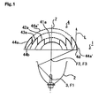
- Fig. 1 is a cross-sectional view showing a first embodiment of a projector type lamp 1 according to the present invention.
- the projector type lamp 1 is composed of: an ellipse group reflector 2 having a first focal point F1 and a second focal point F2 and that is formed, for example, as a spheroid-of-revolution surface; a light source 3 arranged in the vicinity of the first focal point F1 of the reflector 2, such as a halogen bulb or a metal halide lamp; and a projection lens 4 arranged such that a focal point F3 thereof is located in the vicinity of the second focal point F2 on which light emitted from the light source 3 and reflected by the reflector 2 converges.
- the projector type lamp 1 of the first embodiment has basically the same structure as the conventional example.
- the ellipse group reflector can be defined as a reflector having a curved surface having an ellipse or its similar shape as a whole, such as a rotated elliptic surface, a complex elliptic surface, an ellipsoidal surface, an elliptic cylindrical surface, an elliptical free-curved surface, or combination thereof.
- the projector type lamp 1 is characterized in that the projection lens 4 is formed by combining together portions of a plurality of projection lenses that have an identical optical axis center Z and focal point yet are different in their outer diameters (the lenses are hereinafter referred to as "unprocessed projection lens").
- the entire projection lens 4 appears substantially rectangular when viewed in a direction of the optical axis Z.
- Fig. 2 One example of procedures for fabricating such a projection lens 4 will be described below with reference to Fig. 2. That is, as depicted in Fig. 2, assuming four pieces of unprocessed projection lenses 41, 42, 43, and 44 that have an identical optical axis center Z, focal length, and focal point, but yet are different in their outer diameters.
- processed projection lens pieces 41, 42, 43, and 44 are processed or cut into processed projection lens pieces 41, 42, 43, and 44 (hereinafter referred to "processed projection lens piece or element").
- the processed pieces are combined together to form a single projection lens 4 having a substantially rectangular configuration as a whole.
- the lines representing the contour of the rectangle of the projection lens according to the invention are referred to as "contour line.”
- the projection lenses 41, 42, 43, 44 before and after processing are denoted by the same reference numeral herein for the sake of convenience.
- the first unprocessed projection lens 41 located innermostly with respect to the optical axis Z (hereinafter called as "optical axis center Z), is sectioned horizontally (viewing the drawing) along a line P1-P2 and a line P3-P4 (they correspond to parts of the contour lines of the long sides of the projection lens 4) so as to leave a given dimension h (it corresponds to the length of the short side of the rectangle), and is then sectioned vertically along a line P1-P4 and a line P2-P3 so as not to leave any circumferential portion of original lens 41.
- the first processed projection lens element 41 located innermostly with respect to the optical axis center Z, is configured such that its lens surface 41a has a substantially rectangular shape defined by the line P1-P2-P3-P4, as viewed from the front (in the optical axis Z direction).
- the first processed projection lens element 41 is used as a reference lens. Note that, in the illustrative example, the lens surface 41a is given a square shape to make the most of the entire area of the projection lens element 41.
- the second unprocessed projection lens 42 i.e. the second-innermost lens with respect to the optical axis center Z, is hollowed out so as to receive the first processed projection lens element 41.
- intersections Q1, Q2, Q3, and Q4 are determined, of which Q1 and Q2 are points of intersection between the extension line of the upper cutting line P1-P2 of the first processed projection lens element 41 (a part of the contour line of the long side of the projection lens 4) and the circumference of the second unprocessed projection lens 42 being zero in thickness; and Q3 and Q4 are points of intersection between the extension line of the lower cutting line P3-P4 and the same circumference.
- the unprocessed second projection lens 42 is sectioned horizontally along a line Q1-Q2 and a line Q3-Q4 so as to leave the given dimension h, and is then sectioned vertically along a line Q1-Q4 and a line Q2-Q3 so as not to leave any circumferential portion of original lens 42.
- the third unprocessed projection lens 43 i.e. the third-innermost lens with respect to the optical axis center Z, is hollowed out so as to receive the second processed projection lens element 42.
- intersections R1, R2, R3, and R4 are determined, of which R1 and R2 are points of intersection between the extension line of the upper cutting line Q1-Q2 of the second processed projection lens element 42 (a part of the contour line of the long side of the projection lens 4) and the circumference of the third unprocessed projection lens 43 being zero in thickness; and R3 and R4 are points of intersection between the extension line of the lower cutting line Q3-Q4 and the same circumference.
- the third unprocessed projection lens 43 is sectioned horizontally along a line R1-R2 and a line R3-R4 so as to leave the given dimension h, and is then sectioned vertically along a line R1-R4 and a line R2-R3 so as not to leave any circumferential portion of original lens 43.
- intersections S1, S2, S3, and S4 are determined, of which S1 and S2 are points of intersection between the extension line of the upper cutting line R1-R2 of the third processed projection lens element 43 (a part of the contour line of the long side of the projection lens 4) and the circumference of the fourth unprocessed projection lens 44 being zero in thickness; and S3 and S4 are points of intersection between the extension line of the lower cutting line R3-R4 and the same circumference.
- the fourth unprocessed projection lens 44 is sectioned horizontally along a line S1-S2 and a line S3-S4 so as to leave the given dimension h, and is then sectioned vertically along a line S1-S4 and a line S2-S3 so as not to leave any circumferential portion of original lens 44.
- the four processed projection lens elements 41, 42, 43, and 44 that have identical optical axis center Z and focal point yet are different in their outer dimension, are combined together, thereby realizing the projection lens 4 which appears substantially rectangular when viewed in the optical axis Z direction (from the front).
- Fig. 3 is a perspective view illustrating the entire projection lens 4.
- the lens surfaces 41a, 42a, 43a, and 44a of the processed projection lens elements 41, 42, 43, and 44 are continuous with one another through stepped portions 42b, 43b, and 44b that are arranged substantially parallel to the optical axis Z. Note that, a face including points where the surface of the processed projection lens pieces are zero in thickness is formed by the processed projection lens elements and the face is placed on a transparent plate having an appropriate thickness.
- a flange 4c is provided in the vicinity of the contour of the plate.
- dotted lines indicate a virtual lens surface 44a' which is obtained in a case where the projection lens 4 is composed solely of the unprocessed projection lens 44 located outermost with respect to the optical axis center Z.
- the projection lens 4 of the embodiment according to the present invention is made slimmer and lighter in weight in its entirety.
- the projection lens 4 unlike a conventional circular projection lens, assumes a shape in a novel design when seen from the front, that is, it offers a differentiating feature in terms of its outward appearance.
- the junctions among the lens surfaces 41a, 42a, 43a, and 44a are formed as stepped portions that are arranged substantially parallel to the optical axis Z.
- the projection lens 4 including all projection lens elements 41, 42, 43, 44 and the plate, if any, is formed through a single process of molding.
- the projection lens is formed by combining separately processed projection lens elements 41, 42, 43, 44 on a plate.
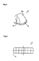
- the processed projection lens element 44 located outermost with respect to the optical axis center Z, is sectioned vertically along the lines S1-S4 and S2-S3 so as to create a sectioned surface 4d (at the short sides of the rectangle), it may also be designed in accordance with a second embodiment as shown in Fig. 4.
- a circular arc shape R which constitutes part of the contour of the unprocessed projection lens 44, is left intact instead of creating the sectioned surface 4d (i.e., without being sectioned along the lines S1-S4 and S2-S3).
- the entire projection lens 4 appears substantially rectangular when viewed in the optical axis Z direction (from the front), and parts of the contour of the unprocessed lens 44 form the pair of short sides of the rectangle.
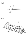
- Fig. 6 shows a light distribution pattern of the projector type lamp 1 employing the projection lens 4 constructed in accordance with the first and second embodiments.
- a light distribution pattern portion N is formed by the light having passed through the outermost lens surface 44a
- a light distribution pattern M is formed by the light having passed through the inner lens surfaces 41a, 42a, and 43a.
- light having passed through the outer lens portions of the projection lens 4 tends to converge more centrally.
- Fig. 6 shows a low beam light distribution pattern, as shown in Fig. 13, in a case where the shade 94 is retracted from an optical path traveling from the light source 92 to the projection lens 93, a high beam light distribution pattern can be obtained.
- the projection lens 4 is mounted laterally on a vehicle body, although some light emitted from the light source 3 is incident on the stepped portions 42b, 43b, and 44b of the processed projection lens elements 41, 42, 43, and 44, such incident light is not effective light for the illumination.
- the appearance of the headlamp in a non-lighting state can be made more novel without having an adverse effect on the projection light color.
- the projection lens 4 may be designed, in accordance with a third embodiment, so as to obtain laterally diffused light distribution.
- the outermost processed projection lens element 44 is replaced by a processed lens which has a lens surface 44a whose longitudinal sectional profile shows a straight line which is substantially perpendicular to the optical axis Z.
- the lens surface 44a does not have its focus on the identical focal point F3, but it has a line focus on a solid line passing through the identical focal point F3.
- the solid line is perpendicular to the optical axis Z of the projector type lamp, and extends horizontally.
- parallel light L shown in Fig. 1 (corresponding to the light distribution portion N hatched in Fig. 6), which is emitted from the lens surface 44a of the processed projection lens element 44 of the first embodiment, is allowed to diffuse laterally as light L' shown in Fig. 9.
- the basic profile of the light distribution pattern is formed by the lens surface 41a.
- the luminance of a predetermined portion within the light distribution pattern is increased by the lens surfaces 42a and 43a.
- the lens surface 44a may be designed so as to illuminate outside of the basic profile of the light distribution pattern, or to illuminate a predetermined portion within the light distribution pattern.
- the outermost lens surface 44a has its longitudinal sectional profile showing a straight line which is substantially perpendicular to the optical axis Z
- one or more of the lens surfaces 42a, 43a, and 44a may have its longitudinal sectional profile showing a straight line which is substantially perpendicular to the optical axis Z, as required.
- the outermost lens surface 44a may have its longitudinal sectional profile showing a circular arc which is substantially perpendicular to the optical axis Z
- one or more of the lens surfaces 42a, 43a, and 44a may have its longitudinal sectional profile showing a circular arc which is substantially perpendicular to the optical axis Z, as required.
- the circular arc of the outermost lens surface 42a, 43a, and/or 44a has a focal point located at any point on a solid line passing through the identical focal point F3.
- the solid line is perpendicular to the optical axis Z of the projector type lamp, and extends horizontally.
- the projection lens 4 is described as arranged so as to have a laterally elongated rectangular shape, it may be arranged so as to have a vertically elongated rectangular shape, depending on the light distribution pattern required. This arrangement can be achieved simply by turning the same projection lens 4 by 90 degrees. In this case, as shown in Fig. 10, the light incident on the stepped portions 42b, 43b, and 44b travels in an upward direction, which affects the light distribution pattern as glare. Therefore, the vertically elongated rectangular shape should preferably be adopted only for the high beam light distribution pattern which is allowed to include upward beams.
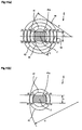
- the lines P1-P2, P2-P3, Q1-Q4, Q2-Q3, R1-R4, and R2-R3 are each defined by a straight line, they may be defined by a curve. So long as a plurality of projection lens elements used in combination are arranged with their centers located on the same optical axis, the boundary portions (lines P1-P2, P2-P3, Q1-Q4, Q2-Q3, R1-R4, and R2-R3) can be formed in any given shape. For example, the farther the center of the circular arc constituting the boundary portion is located away from the projection lens, the more the shape of the boundary portion approaches a straight line (see to Figs. 11(a)-(b)).
- the projection lens 4 is described as formed of four pieces of processed projection lens elements combined together, it may be formed by combining together two or more projection lens elements.
- the projection lens 4 is described as used for a vehicle lamp, the lens configuration described thus far may be suitably used for any other application.
Landscapes
- Engineering & Computer Science (AREA)
- General Engineering & Computer Science (AREA)
- Non-Portable Lighting Devices Or Systems Thereof (AREA)
Abstract
Description
- The present invention relates to a lamp for vehicles such as a headlamp, a fog lamp, or the like, and more particularly to a projector type lamp. A projector type lamp used herein is composed of: an ellipsoidal reflector having a first focal point and a second focal point that is formed, for example, as a spheroid-of-revolution surface, or an elliptic free-curved surface; a light source arranged in the vicinity of the first focal point of the reflector; a projection lens arranged with its focal point located in the vicinity of the second focal point on which light emitted from the light source and reflected by the reflector converges; and a shade, as required, for controlling light distribution characteristics, arranged in the vicinity of the focal point of the projection lens.
- An example of a conventional
projector type lamp 90 of the type mentioned above is shown in Fig. 13. Theprojector type lamp 90 is composed of: areflector 91 which is formed, for example, as a spheroid-of-revolution surface having a first focal point f1 and a second focal point f2; alight source 92 arranged in the vicinity of the first focal point f1 of thereflector 91; and aprojection lens 93 arranged such that a focal point f3 thereof is located in the vicinity of the second focal point f2 on which light emitted from thelight source 92 and reflected by thereflector 91 converges. - Here, it is preferable to additionally employ a
shade 94. Only those light beams of the light beams converging on the second focal point, which are required for producing an intended light distribution characteristic, are permitted to pass by theshade 94, and unnecessary portions are blocked thereby. This makes it possible to realize aprojector type lamp 90 having appropriate light distribution characteristics such that, for example, when theshade 94 is located in the light path, a passing beam (hereafter referred to as "low beam") is turned on, and, when theshade 94 is retracted from the light path, a driving beam (hereafter referred to as "high beam") is turned on. - However, in the conventional
projector type lamp 90, once the light having converged on the second focal point f2 , which is expected to diverge radially thereafter, is condensed by theprojection lens 93 to such an extent that it is projected in an illumination direction. Thus, the projected light is apt to diverge radially even after passing through theprojection lens 93. This makes it difficult to focus the light at a desired position satisfactorily. - Accordingly, the
projector type lamp 90, though having the advantage of producing a light distribution characteristic of a desired profile, particularly in forming a cut-off line of a low beam, has limited degree of freedom in luminance distribution within the profile of the light distribution characteristic and thus cannot be suitably used as a lamp which is required to exhibit, in particular, an illumination characteristic, in which a faraway area is more brightly illuminated than a front or closer area, such as it is required for a headlamp for the high-beam distribution. - Moreover, the
projection lens 93 appears circular when seen from the front, and, when theprojector type lamp 90 is mounted on a vehicle, only theprojection lens 93 is visible. Therefore, any lamp of this type provides a similar impression, and it is basically impossible to render design variations according to the type of a vehicle. That is, the conventionalprojector type lamp 90 has a disadvantage because of a lack of design flexibility. - Further, since the heat produced by the
light source 92 is considerably concentrated on theprojection lens 93, a sharp temperature rise is inevitable. This necessitates the use of a glass member which is excellent in heat resistance, leading to an increase in costs and making it difficult to achieve a weight reduction. These problems need to be solved. - Note that, in order to obtain the above-described illumination characteristics, namely, to illuminate a faraway area more brightly than a front area, and to increase the flexibility in design, there has been proposed a horizontally elongated projection lens. This projection lens is formed by cutting end portions in a vertical direction of the projection lens so that it appears substantially oval when viewed in a direction of an optical axis. However, such a horizontally elongated configuration cannot be realized without using an unprocessed projection lens having a large outer diameter in terms of the need for cutting, and, the larger the outer diameter of a lens, the greater the thickness can be. This makes a weight reduction impossible.
- In view of the foregoing, a first object of the present invention is to provide a projector type lamp having an excellent light illumination characteristic in which a faraway area is illuminated more brightly than a front area, being made thin and lighter in weight, and having a shape in a novel design when seen from the front, that is, it offers a differentiating feature in terms of the outward appearance unlike a conventional circular projection lens. A second object of the present invention is to provide a projector type lamp making it possible to use light coming from a reflecting surface. Such light has never been utilized in a conventional Fresnel lens so far because the light becomes glare light. Thereby it is possible to increase the quantity of light available for lighting to be emitted from a vehicle lamp and at the same time reducing the weight of the lens and not causing glare light.
- To attain the above objects, a projector type lamp according to the present invention is a projector type lamp comprising: an ellipse group reflector having a first focal point and a second focal point; a light source arranged in a vicinity of the first focal point of the reflector; and a projection lens arranged with its focal point located in a vicinity of the second focal point on which light emitted from the light source and reflected by the reflector converges. In this constitution, the projection lens is formed by combining a plurality of processed projection lens elements that are fabricated by processing a plurality of unprocessed projection lenses having identical optical axis center and focal point yet are different in their outer diameters, the projection lens has substantially a rectangular shape in a plan view seen in an optical axis direction, and boundary portions between the plurality of processed projection lens elements in the plan view are composed of a line connecting points of intersection between a contour line of the projection lens and a line defining part of each unprocessed projection lens being zero in thickness, as viewed in the optical axis direction. Thereby, the lens surfaces of the processed projection lens elements are continuous with one another through stepped portions of which the longitudinal section has a straight line substantially parallel to the optical axis in a longitudinal section of the projection lens.
- With this projector type lamp according to the invention, it is possible to obtain an excellent light illumination characteristic in which a faraway area is illuminated more brightly than a front area, which is necessitated in a headlamp for vehicles. Moreover, the projection lens can be made slimmer and lighter in weight, and, unlike a conventional circular projection lens, it has a shape in a novel design when seen from the front, that is, it offers a differentiating feature in terms of the outward appearance. Further, the junctions among the lens surfaces constituting the projection lens are formed as stepped portions that are arranged substantially parallel to the optical axis Z. This arrangement makes it possible to use a portion of light coming from a reflecting surface. This light has never been utilized before in a conventional Fresnel lens, which has a circular arc shape as a whole, for the reason that the light becomes glare light. As a result, the weight of the lens can be reduced, and a quantity of light available for lighting to be emitted from a vehicle lamp can be increased without causing glare light.
- In the projector type lamp as constituted above, the line constituting at least one of the boundary portions between the plurality of processed projection lens elements may be a circular arc which has its center at a position away from the optical axis of the lamp, or it may be a substantially straight line.
- Furthermore, the processed projection lens element, located innermostly with respect to the optical axis center out of the processed projection lens elements, may be configured such that its lens surface appears as a square in a plan view when viewed in the direction of the optical axis.
- The stepped portion between the processed projection lens elements may be colored or covered with a colored member. Thus, the appearance of the headlamp in a non-lighting state can be made more original or innovative without having an adverse effect on the projection light color.
- The short sides of the rectangle of the projection lens may be composed of parts of a circular arc or a contour line of the unprocessed projection lens located outermost. This provides an improved design flexibility.
- At least one of the plurality of processed projection lens elements may be replaced by a lens whose longitudinal section has a substantially straight line on its lens surface, which line is substantially perpendicular to the optical axis. Alternatively, it may have a curve which is convex with respect to the optical axis, for providing a predetermined luminous distribution. This provides an appropriate luminous distribution, for example, a distribution in which light is diffused in the right and left directions.
- Additional features, advantages, and embodiments of the invention may be set forth or apparent from consideration of the following detailed description, drawings, and claims. Moreover, it is to be understood that both the foregoing summary of the invention and the following detailed description are exemplary and intended to provide further explanation without limiting the scope of the invention as claimed.
- These and other objects and advantages of the present invention will become clear from the following description with reference to the accompanying drawings, wherein:
- Fig. 1 is a cross-sectional view showing a first embodiment of a projector type lamp according to the present invention;
- Fig. 2 is a view in order to assist in explaining the procedure for fabricating a projection lens;
- Fig. 3 is a perspective view showing the first embodiment of the projection lens;
- Fig. 4 is a perspective view showing a principal portion of a second embodiment of the projection lens;
- Fig. 5 is a front view showing the second embodiment of the projection lens;
- Fig. 6 is a view showing a light distribution pattern of the projector type lamp according to the present invention;
- Fig. 7 is a perspective view showing a colored member;
- Fig. 8 is a perspective view showing a third embodiment of the projection lens;
- Fig. 9 is a cross-sectional view showing the third embodiment of the projection lens;
- Fig. 10 is a vertical sectional view showing an optical path as observed when the first embodiment of the projection lens is arranged vertically;
- Fig. 11(a) is a view in order to assist in explaining variations of the projection lens according to the present invention;
- Fig. 11(b) is a view in order to assist in explaining a further variation of the projection lens according to the present invention;
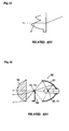
- Fig. 12 is a vertical sectional view showing an optical path as observed in a conventional Fresnel lens; and
- Fig. 13 is a vertical sectional view showing a conventional vehicle lamp.
-
- The present invention will be described in detail hereinafter with reference to preferred embodiments shown in the accompanying drawings.
- Fig. 1 is a cross-sectional view showing a first embodiment of a projector type lamp 1 according to the present invention. The projector type lamp 1 is composed of: an
ellipse group reflector 2 having a first focal point F1 and a second focal point F2 and that is formed, for example, as a spheroid-of-revolution surface; alight source 3 arranged in the vicinity of the first focal point F1 of thereflector 2, such as a halogen bulb or a metal halide lamp; and aprojection lens 4 arranged such that a focal point F3 thereof is located in the vicinity of the second focal point F2 on which light emitted from thelight source 3 and reflected by thereflector 2 converges. Further, a shade (not shown) for controlling light distribution characteristics is arranged in the vicinity of the focal point F3 of theprojection lens 4, as required. In these respects, the projector type lamp 1 of the first embodiment has basically the same structure as the conventional example. Throughout the present invention, the ellipse group reflector can be defined as a reflector having a curved surface having an ellipse or its similar shape as a whole, such as a rotated elliptic surface, a complex elliptic surface, an ellipsoidal surface, an elliptic cylindrical surface, an elliptical free-curved surface, or combination thereof. - According to the present invention, the projector type lamp 1 is characterized in that the
projection lens 4 is formed by combining together portions of a plurality of projection lenses that have an identical optical axis center Z and focal point yet are different in their outer diameters (the lenses are hereinafter referred to as "unprocessed projection lens"). Theentire projection lens 4 appears substantially rectangular when viewed in a direction of the optical axis Z. One example of procedures for fabricating such aprojection lens 4 will be described below with reference to Fig. 2. That is, as depicted in Fig. 2, assuming four pieces ofunprocessed projection lenses projection lens pieces single projection lens 4 having a substantially rectangular configuration as a whole. It should be noted that the lines representing the contour of the rectangle of the projection lens according to the invention are referred to as "contour line." Theprojection lenses - Firstly, the first
unprocessed projection lens 41, located innermostly with respect to the optical axis Z (hereinafter called as "optical axis center Z), is sectioned horizontally (viewing the drawing) along a line P1-P2 and a line P3-P4 (they correspond to parts of the contour lines of the long sides of the projection lens 4) so as to leave a given dimension h (it corresponds to the length of the short side of the rectangle), and is then sectioned vertically along a line P1-P4 and a line P2-P3 so as not to leave any circumferential portion oforiginal lens 41. In this way, the first processedprojection lens element 41, located innermostly with respect to the optical axis center Z, is configured such that itslens surface 41a has a substantially rectangular shape defined by the line P1-P2-P3-P4, as viewed from the front (in the optical axis Z direction). The first processedprojection lens element 41 is used as a reference lens. Note that, in the illustrative example, thelens surface 41a is given a square shape to make the most of the entire area of theprojection lens element 41. - Next, the second
unprocessed projection lens 42, i.e. the second-innermost lens with respect to the optical axis center Z, is hollowed out so as to receive the first processedprojection lens element 41. Then, intersections Q1, Q2, Q3, and Q4 are determined, of which Q1 and Q2 are points of intersection between the extension line of the upper cutting line P1-P2 of the first processed projection lens element 41 (a part of the contour line of the long side of the projection lens 4) and the circumference of the secondunprocessed projection lens 42 being zero in thickness; and Q3 and Q4 are points of intersection between the extension line of the lower cutting line P3-P4 and the same circumference. Subsequently, likewise as the first processedprojection lens element 41, the unprocessedsecond projection lens 42 is sectioned horizontally along a line Q1-Q2 and a line Q3-Q4 so as to leave the given dimension h, and is then sectioned vertically along a line Q1-Q4 and a line Q2-Q3 so as not to leave any circumferential portion oforiginal lens 42. - Thirdly, the third
unprocessed projection lens 43, i.e. the third-innermost lens with respect to the optical axis center Z, is hollowed out so as to receive the second processedprojection lens element 42. Then, intersections R1, R2, R3, and R4 are determined, of which R1 and R2 are points of intersection between the extension line of the upper cutting line Q1-Q2 of the second processed projection lens element 42 (a part of the contour line of the long side of the projection lens 4) and the circumference of the thirdunprocessed projection lens 43 being zero in thickness; and R3 and R4 are points of intersection between the extension line of the lower cutting line Q3-Q4 and the same circumference. Subsequently, likewise as the first and second processedprojection lens elements unprocessed projection lens 43 is sectioned horizontally along a line R1-R2 and a line R3-R4 so as to leave the given dimension h, and is then sectioned vertically along a line R1-R4 and a line R2-R3 so as not to leave any circumferential portion oforiginal lens 43. - Lastly, the fourth
unprocessed projection lens 44, located outermost with respect to the optical axis center Z, is hollowed out so as to receive the third processedprojection lens element 43. Then, intersections S1, S2, S3, and S4 are determined, of which S1 and S2 are points of intersection between the extension line of the upper cutting line R1-R2 of the third processed projection lens element 43 (a part of the contour line of the long side of the projection lens 4) and the circumference of the fourthunprocessed projection lens 44 being zero in thickness; and S3 and S4 are points of intersection between the extension line of the lower cutting line R3-R4 and the same circumference. Subsequently, likewise as the first, second, and third processedprojection lens elements unprocessed projection lens 44 is sectioned horizontally along a line S1-S2 and a line S3-S4 so as to leave the given dimension h, and is then sectioned vertically along a line S1-S4 and a line S2-S3 so as not to leave any circumferential portion oforiginal lens 44. - In this way, the four processed
projection lens elements projection lens 4 which appears substantially rectangular when viewed in the optical axis Z direction (from the front). - Fig. 3 is a perspective view illustrating the
entire projection lens 4. The lens surfaces 41a, 42a, 43a, and 44a of the processedprojection lens elements portions flange 4c is provided in the vicinity of the contour of the plate. In this figure, dotted lines indicate avirtual lens surface 44a' which is obtained in a case where theprojection lens 4 is composed solely of theunprocessed projection lens 44 located outermost with respect to the optical axis center Z. As compared with this, theprojection lens 4 of the embodiment according to the present invention is made slimmer and lighter in weight in its entirety. Moreover, theprojection lens 4, unlike a conventional circular projection lens, assumes a shape in a novel design when seen from the front, that is, it offers a differentiating feature in terms of its outward appearance. Further, the junctions among thelens surfaces surface 2. This light has never been utilized in a conventional Fresnel lens having a circular arc shape as a whole, as shown in Fig. 12. At the same time it is possible to reduce the weight of the lens, and to increase a quantity of light available for lighting to be emitted from a vehicle lamp 1. In accordance with a preferred production method theprojection lens 4 including allprojection lens elements projection lens elements - Although the processed
projection lens element 44, located outermost with respect to the optical axis center Z, is sectioned vertically along the lines S1-S4 and S2-S3 so as to create a sectionedsurface 4d (at the short sides of the rectangle), it may also be designed in accordance with a second embodiment as shown in Fig. 4. Here a circular arc shape R, which constitutes part of the contour of theunprocessed projection lens 44, is left intact instead of creating the sectionedsurface 4d (i.e., without being sectioned along the lines S1-S4 and S2-S3). In this case, as shown in Fig. 5, theentire projection lens 4 appears substantially rectangular when viewed in the optical axis Z direction (from the front), and parts of the contour of theunprocessed lens 44 form the pair of short sides of the rectangle. - Fig. 6 shows a light distribution pattern of the projector type lamp 1 employing the
projection lens 4 constructed in accordance with the first and second embodiments. A light distribution pattern portion N is formed by the light having passed through theoutermost lens surface 44a, and a light distribution pattern M is formed by the light having passed through theinner lens surfaces projection lens 4 tends to converge more centrally. In view of the above, by properly adjusting the number and the shape of the processedprojection lens elements shade 94 is retracted from an optical path traveling from thelight source 92 to theprojection lens 93, a high beam light distribution pattern can be obtained. - In a case where the
projection lens 4 is mounted laterally on a vehicle body, although some light emitted from thelight source 3 is incident on the steppedportions projection lens elements projection lens 4 with a colored member 4' for connecting or covering the steppedportions - Further, although the above explanation has been given as to the shape of the
projection lens 4 intended for improving the distant visibility, theprojection lens 4 may be designed, in accordance with a third embodiment, so as to obtain laterally diffused light distribution. In this case, as shown in Figs. 8 and 9, the outermost processedprojection lens element 44 is replaced by a processed lens which has alens surface 44a whose longitudinal sectional profile shows a straight line which is substantially perpendicular to the optical axis Z. In this case, thelens surface 44a does not have its focus on the identical focal point F3, but it has a line focus on a solid line passing through the identical focal point F3. The solid line is perpendicular to the optical axis Z of the projector type lamp, and extends horizontally. In this configuration, parallel light L shown in Fig. 1 (corresponding to the light distribution portion N hatched in Fig. 6), which is emitted from thelens surface 44a of the processedprojection lens element 44 of the first embodiment, is allowed to diffuse laterally as light L' shown in Fig. 9. For example, in order for the low beam light distribution pattern to be wider horizontally, the basic profile of the light distribution pattern is formed by thelens surface 41a. Then, the luminance of a predetermined portion within the light distribution pattern is increased by the lens surfaces 42a and 43a. Thelens surface 44a may be designed so as to illuminate outside of the basic profile of the light distribution pattern, or to illuminate a predetermined portion within the light distribution pattern. - Further, while in Fig. 9, an example is shown in which only the
outermost lens surface 44a has its longitudinal sectional profile showing a straight line which is substantially perpendicular to the optical axis Z, one or more of thelens surfaces outermost lens surface 44a may have its longitudinal sectional profile showing a circular arc which is substantially perpendicular to the optical axis Z, or one or more of thelens surfaces outermost lens surface - Further, while in the above-described embodiments, the
projection lens 4 is described as arranged so as to have a laterally elongated rectangular shape, it may be arranged so as to have a vertically elongated rectangular shape, depending on the light distribution pattern required. This arrangement can be achieved simply by turning thesame projection lens 4 by 90 degrees. In this case, as shown in Fig. 10, the light incident on the steppedportions - In addition, while in the above-described embodiments, the lines P1-P2, P2-P3, Q1-Q4, Q2-Q3, R1-R4, and R2-R3 are each defined by a straight line, they may be defined by a curve. So long as a plurality of projection lens elements used in combination are arranged with their centers located on the same optical axis, the boundary portions (lines P1-P2, P2-P3, Q1-Q4, Q2-Q3, R1-R4, and R2-R3) can be formed in any given shape. For example, the farther the center of the circular arc constituting the boundary portion is located away from the projection lens, the more the shape of the boundary portion approaches a straight line (see to Figs. 11(a)-(b)).
- Further, while in the above-described embodiments, the
projection lens 4 is described as formed of four pieces of processed projection lens elements combined together, it may be formed by combining together two or more projection lens elements. - Note that, while in the above-described embodiments, the
projection lens 4 is described as used for a vehicle lamp, the lens configuration described thus far may be suitably used for any other application. - While there has been described what are at present considered to be preferred embodiments of the present invention, it will be understood that various modifications may be made thereto, and it is intended that the appended claims cover all such modifications as long as they fall within the scope of the appended claims.
Claims (10)
- A projector type lamp (1) comprising:an ellipse group reflector (2) having a first focal point (f1) and a second focal point (f2);a light source (3) arranged in the vicinity of the first focal point of the reflector (2); anda projection lens (4) having its focal point located in a vicinity of the second focal point (f2) on which light emitted from the light source and reflected by the reflector (2) converges,the projection lens (4) being formed by combining a plurality of processed projection lens elements (41, 42, 43, 44) that are fabricated by processing a plurality of unprocessed projection lenses having an identical optical center axis (Z) and an identical focal point yet different outer diameters,the projection lens (4) having substantially a rectangular shape in a plan view as seen in an optical axis direction, andboundary surface portions (42b, 43b, 44b) between the plurality of processed projection lens elements (41, 42, 43), which, in the plan view, are composed of a line connecting points of intersection between a contour line of the projection lens and a line which is defined by a part of each unprocessed projection lens which has zero thickness, as viewed in the optical axis direction,so that lens surfaces (41a, 42a, 43a, 44a) of the processed projection lens elements (41, 42, 43, 44) are continuous with one another through stepped portions (42b, 43b, 44b) of which longitudinal sectional views have a straight line substantially parallel to the optical axis in a longitudinal section (fig. 1) of the projection lens.
- The projector type lamp according to claim 1, wherein
the line constituting at least one of the boundary portions between the plurality of processed projection lens elements is a circular arc which has its center at a position away from the optical axis of the lamp (3). - The projector type lamp according to claim 2, wherein
the line constituting at least one of the boundary portions (44a)between the plurality of processed projection lens elements is a substantially straight line. - The projector type lamp according to any one of the claims 1-3, wherein
the processed projection lens element, located innermostly with respect to the optical axis center out of the processed projection lens elements, is so configured that its lens surface appears as a square in a plan view when viewed in the optical axis direction. - The projector type lamp according to any one of the claims 1-4, wherein
the stepped portion between the processed projection lens elements is colored or covered with a colored member (4'). - The projector type lamp according to claim 1, wherein
short sides of the rectangle of the projection lens are composed of parts of a circular arc or a contour line of the unprocessed projection lens located outermost. - The projector type lamp according to claim 1, wherein
at least one of the plurality of processed projection lens elements is replaced by a lens whose longitudinal section has a substantially straight line on its lens surface, which lines is substantially perpendicular to the optical axis. - The projector type lamp according to claim 1, wherein
at least one of the plurality of processed projection lens elements is replaced by a lens whose longitudinal section has a curve which is convex with respect to the optical axis, for providing a predetermined luminous distribution, wherein preferably
at least one of the plurality of processed projection lens elements is replaced by a lens whose longitudinal section has a circular arc which is substantially perpendicular to the optical axis Z. - A projector type lamp (1) comprising:an ellipse group reflector (2) having a first focal point (f1) and a second focal point (f2);a light source (3) arranged in the vicinity of the first focal point of the reflector (2); anda projection lens (4) having its focal point located in a vicinity of the second focal point (f2) on which light emitted from the light source and reflected by the reflector (2) converges,the projection lens (4) being formed by combining a plurality of processed projection lens elements (41, 42, 43, 44) that are fabricated by processing a plurality of unprocessed projection lenses having an identical optical center axis (Z) and an identical focal point yet different outer diameters,the projection lens (4) having substantially a rectangular shape in a plan view as seen in an optical axis direction.
- A projector type lamp (1) comprising:wherein at least one of the projection lens (4) having substantially a rectangular shape in a plan view as seen in an optical axis direction.an ellipse group reflector (2) having a first focal point (f1) and a second focal point (f2) ;a light source (3) arranged in the vicinity of the first focal point of the reflector (2); anda projection lens (4) having its focal point located in a vicinity of the second focal point (f2) on which light emitted from the light source and reflected by the reflector (2) converges,the projection lens (4) being formed by combininga plurality of processed projection lens elements (41, 42, 43) that are fabricated by processing a plurality of unprocessed projection lenses having an identical optical center axis (Z) and an identical focal point (F3) yet different outer diameters,and at least one processed projection lens elements (44) that is fabricated by processing at least one unprocessed projection lens having an identical optical center axis (Z) and a focal point located at any point on a solid line passing through the identical focal point (F3), wherein the solid line is perpendicular to the optical axis Z and extends horizontally,
Applications Claiming Priority (2)
| Application Number | Priority Date | Filing Date | Title |
|---|---|---|---|
| JP2001085090 | 2001-03-23 | ||
| JP2001085090A JP3634763B2 (en) | 2001-03-23 | 2001-03-23 | Projector type lamp |
Publications (3)
| Publication Number | Publication Date |
|---|---|
| EP1243844A2 true EP1243844A2 (en) | 2002-09-25 |
| EP1243844A3 EP1243844A3 (en) | 2004-03-17 |
| EP1243844B1 EP1243844B1 (en) | 2010-06-16 |
Family
ID=18940661
Family Applications (1)
| Application Number | Title | Priority Date | Filing Date |
|---|---|---|---|
| EP02006802A Expired - Lifetime EP1243844B1 (en) | 2001-03-23 | 2002-03-25 | Projector type lamp |
Country Status (4)
| Country | Link |
|---|---|
| US (1) | US6700316B2 (en) |
| EP (1) | EP1243844B1 (en) |
| JP (1) | JP3634763B2 (en) |
| DE (1) | DE60236707D1 (en) |
Cited By (5)
| Publication number | Priority date | Publication date | Assignee | Title |
|---|---|---|---|---|
| FR2878020A1 (en) * | 2004-11-18 | 2006-05-19 | Valeo Vision Sa | LIGHTING AND / OR SIGNALING DEVICE FOR A MOTOR VEHICLE PRODUCING A BEAM ON THE SIDE OF A MOTOR VEHICLE |
| CN102162617A (en) * | 2010-02-17 | 2011-08-24 | 株式会社小糸制作所 | Lamp unit |
| CN103712146A (en) * | 2012-10-03 | 2014-04-09 | 株式会社小糸制作所 | Vehicle lamp |
| CN105042511A (en) * | 2015-08-14 | 2015-11-11 | 华南理工大学 | Method for forming free-form surfaces of optical lenses of LED motorcycle headlamp |
| DE102007012023B4 (en) * | 2006-03-28 | 2015-12-31 | Varroc Lighting Systems S.R.O | LED projector headlamp with multi-faceted lenses |
Families Citing this family (11)
| Publication number | Priority date | Publication date | Assignee | Title |
|---|---|---|---|---|
| FR2837908B1 (en) * | 2002-03-28 | 2004-06-11 | Valeo Vision | LIGHTING PROJECTOR EQUIPPED WITH A SWIVEL ELLIPTICAL REFLECTOR AND A FIXED LENS FOR THE REALIZATION OF A TURNING BEAM |
| DE10361118B4 (en) * | 2003-12-22 | 2011-12-22 | Auer Lighting Gmbh | Fresnels |
| JP2006071950A (en) * | 2004-09-01 | 2006-03-16 | Canon Inc | Optical equipment |
| DE102007015012A1 (en) * | 2006-03-29 | 2008-01-24 | Stanley Electric Co. Ltd. | lighting device |
| CN101398492A (en) * | 2007-09-24 | 2009-04-01 | 深圳市九洲光电子有限公司 | Optical lens |
| JP2010048850A (en) * | 2008-08-19 | 2010-03-04 | Seiko Epson Corp | Lens array and line head |
| WO2011014161A1 (en) * | 2009-07-28 | 2011-02-03 | Hewlett-Packard Development Company, L.P. | Illuminated latch |
| JP2013101881A (en) * | 2011-11-09 | 2013-05-23 | Stanley Electric Co Ltd | Vehicle headlamp |
| JP6131571B2 (en) * | 2012-11-13 | 2017-05-24 | 市光工業株式会社 | Vehicle lighting |
| KR102673141B1 (en) | 2021-06-22 | 2024-06-10 | 현대모비스 주식회사 | Lamp for vehicle and vehicle including the same |
| JP7817904B2 (en) * | 2022-09-09 | 2026-02-19 | 株式会社小糸製作所 | Lighting unit |
Family Cites Families (17)
| Publication number | Priority date | Publication date | Assignee | Title |
|---|---|---|---|---|
| US1955599A (en) * | 1931-07-30 | 1934-04-17 | Us Holding Corp | Motor vehicle headlight |
| US3743385A (en) * | 1970-04-02 | 1973-07-03 | Anchor Hocking Corp | Fresnel aspheric lens |
| US4198182A (en) * | 1975-09-20 | 1980-04-15 | Lucas Industries Limited | Method of manufacturing a mould for producing a lamp lens element |
| DE3226580A1 (en) * | 1981-12-08 | 1983-06-16 | Robert Bosch Gmbh, 7000 Stuttgart | HEADLIGHTS FOR MOTOR VEHICLES |
| EP0320887B1 (en) * | 1987-12-14 | 1993-08-11 | Ichikoh Industries Limited | Method for forming fresnel-type prism lens |
| JPH01225001A (en) * | 1988-03-01 | 1989-09-07 | Koito Mfg Co Ltd | Headlight for vehicle |
| NL8901077A (en) * | 1989-04-28 | 1990-11-16 | Koninkl Philips Electronics Nv | OPTICAL EXPOSURE SYSTEM AND PROJECTION DEVICE EQUIPPED WITH SUCH A SYSTEM. |
| JP2655741B2 (en) * | 1990-06-25 | 1997-09-24 | 株式会社小糸製作所 | Projection type automotive headlamp |
| US5655832A (en) * | 1992-04-16 | 1997-08-12 | Tir Technologies, Inc. | Multiple wavelength light processor |
| JP2587355Y2 (en) | 1992-12-07 | 1998-12-16 | 株式会社小糸製作所 | Condenser Fresnel lens for projector type lighting |
| JPH06331941A (en) * | 1993-05-19 | 1994-12-02 | Olympus Optical Co Ltd | Projection lens system |
| US5927848A (en) * | 1995-09-14 | 1999-07-27 | Koito Manufacturing Co., Ltd. | Vehicular lamp and lamp body therefor |
| JP3005954B2 (en) * | 1998-04-10 | 2000-02-07 | スタンレー電気株式会社 | Lamp |
| DE29813531U1 (en) * | 1998-07-30 | 1998-11-05 | Docter Optics GmbH, 07318 Saalfeld | Optical component for headlights |
| DE19856281B4 (en) * | 1998-12-07 | 2013-06-13 | Automotive Lighting Reutlingen Gmbh | Headlamp for vehicles according to the projection principle |
| JP3886672B2 (en) | 1999-07-12 | 2007-02-28 | 株式会社小糸製作所 | Vehicle headlamp |
| FR2799153A1 (en) * | 1999-09-30 | 2001-04-06 | Valeo Vision | Injection-compression molding of elliptical convergent Fresnel lens for use in vehicle headlight, uses mold with poly=optical surface |
-
2001
- 2001-03-23 JP JP2001085090A patent/JP3634763B2/en not_active Expired - Fee Related
-
2002
- 2002-03-22 US US10/103,564 patent/US6700316B2/en not_active Expired - Lifetime
- 2002-03-25 DE DE60236707T patent/DE60236707D1/en not_active Expired - Lifetime
- 2002-03-25 EP EP02006802A patent/EP1243844B1/en not_active Expired - Lifetime
Non-Patent Citations (1)
| Title |
|---|
| None |
Cited By (12)
| Publication number | Priority date | Publication date | Assignee | Title |
|---|---|---|---|---|
| FR2878020A1 (en) * | 2004-11-18 | 2006-05-19 | Valeo Vision Sa | LIGHTING AND / OR SIGNALING DEVICE FOR A MOTOR VEHICLE PRODUCING A BEAM ON THE SIDE OF A MOTOR VEHICLE |
| EP1659334A1 (en) * | 2004-11-18 | 2006-05-24 | Valeo Vision | Lighting and/or signaling device for automobile generating a light beam on the side of the automotive vehicle |
| US8602617B2 (en) | 2004-11-18 | 2013-12-10 | Valeo Vision | Lighting and/or signaling device for a motor vehicle producing a light beam on the side of a motor vehicle |
| DE102007012023B4 (en) * | 2006-03-28 | 2015-12-31 | Varroc Lighting Systems S.R.O | LED projector headlamp with multi-faceted lenses |
| CN102162617A (en) * | 2010-02-17 | 2011-08-24 | 株式会社小糸制作所 | Lamp unit |
| EP2357397A3 (en) * | 2010-02-17 | 2012-09-12 | Koito Manufacturing Co., Ltd. | Vehicle headlamp unit |
| US8628226B2 (en) | 2010-02-17 | 2014-01-14 | Koito Manufacturing Co., Ltd. | Vehicle headlamp unit having multiple adjacent projection lenses |
| CN102162617B (en) * | 2010-02-17 | 2014-10-29 | 株式会社小糸制作所 | Lamp unit |
| CN103712146A (en) * | 2012-10-03 | 2014-04-09 | 株式会社小糸制作所 | Vehicle lamp |
| CN103712146B (en) * | 2012-10-03 | 2016-08-17 | 株式会社小糸制作所 | Vehicle Lamps |
| CN105042511A (en) * | 2015-08-14 | 2015-11-11 | 华南理工大学 | Method for forming free-form surfaces of optical lenses of LED motorcycle headlamp |
| CN105042511B (en) * | 2015-08-14 | 2018-04-13 | 华南理工大学 | Forming method for LED motorcycle headlamp optical lens free form surface |
Also Published As
| Publication number | Publication date |
|---|---|
| JP2002289009A (en) | 2002-10-04 |
| JP3634763B2 (en) | 2005-03-30 |
| US20020135280A1 (en) | 2002-09-26 |
| US6700316B2 (en) | 2004-03-02 |
| EP1243844A3 (en) | 2004-03-17 |
| EP1243844B1 (en) | 2010-06-16 |
| DE60236707D1 (en) | 2010-07-29 |
Similar Documents
| Publication | Publication Date | Title |
|---|---|---|
| EP1243844B1 (en) | Projector type lamp | |
| JP3005954B2 (en) | Lamp | |
| US6007223A (en) | Projector type lamp | |
| US6910791B2 (en) | Headlight | |
| JP4548981B2 (en) | Projector type lamp | |
| JP3677720B2 (en) | Projector type headlamp | |
| US6152589A (en) | Lamp | |
| JP3005955B2 (en) | Lamp | |
| EP1008801A2 (en) | A projection-type automobile light | |
| US5067053A (en) | Automotive headlamp | |
| JP4009443B2 (en) | Projector type headlamp | |
| US4945455A (en) | Automotive projector-type headlamp | |
| JP2813853B2 (en) | Reflector for vehicle lighting | |
| US6068391A (en) | Headlight with a twin filament lamp for producing a chopped beam and an unchopped beam | |
| JP3996750B2 (en) | head lamp | |
| JP4062662B2 (en) | Lighting fixtures for vehicles | |
| JPH0337242B2 (en) | ||
| JPH10261302A (en) | Projector type lamp | |
| GB2345335A (en) | Vehicle lamp with a reflector which produces a more uniform light distribution pattern | |
| TWI261097B (en) | The projector headlamp | |
| JPH0319121Y2 (en) | ||
| JPS587526Y2 (en) | automotive headlights | |
| JPH11329004A (en) | Lamp | |
| JP2000149616A (en) | Vehicle lighting | |
| JPH0418402B2 (en) |
Legal Events
| Date | Code | Title | Description |
|---|---|---|---|
| PUAI | Public reference made under article 153(3) epc to a published international application that has entered the european phase |
Free format text: ORIGINAL CODE: 0009012 |
|
| AK | Designated contracting states |
Kind code of ref document: A2 Designated state(s): AT BE CH CY DE DK ES FI FR GB GR IE IT LI LU MC NL PT SE TR |
|
| AX | Request for extension of the european patent |
Free format text: AL;LT;LV;MK;RO;SI |
|
| PUAL | Search report despatched |
Free format text: ORIGINAL CODE: 0009013 |
|
| AK | Designated contracting states |
Kind code of ref document: A3 Designated state(s): AT BE CH CY DE DK ES FI FR GB GR IE IT LI LU MC NL PT SE TR |
|
| AX | Request for extension of the european patent |
Extension state: AL LT LV MK RO SI |
|
| RIC1 | Information provided on ipc code assigned before grant |
Ipc: 7F 21V 5/00 B Ipc: 7F 21S 8/12 A Ipc: 7G 02B 3/08 B |
|
| 17P | Request for examination filed |
Effective date: 20040913 |
|
| AKX | Designation fees paid |
Designated state(s): DE FR GB |
|
| 17Q | First examination report despatched |
Effective date: 20050224 |
|
| GRAP | Despatch of communication of intention to grant a patent |
Free format text: ORIGINAL CODE: EPIDOSNIGR1 |
|
| GRAS | Grant fee paid |
Free format text: ORIGINAL CODE: EPIDOSNIGR3 |
|
| GRAA | (expected) grant |
Free format text: ORIGINAL CODE: 0009210 |
|
| AK | Designated contracting states |
Kind code of ref document: B1 Designated state(s): DE FR GB |
|
| REF | Corresponds to: |
Ref document number: 60236707 Country of ref document: DE Date of ref document: 20100729 Kind code of ref document: P |
|
| PLBE | No opposition filed within time limit |
Free format text: ORIGINAL CODE: 0009261 |
|
| STAA | Information on the status of an ep patent application or granted ep patent |
Free format text: STATUS: NO OPPOSITION FILED WITHIN TIME LIMIT |
|
| 26N | No opposition filed |
Effective date: 20110317 |
|
| REG | Reference to a national code |
Ref country code: DE Ref legal event code: R097 Ref document number: 60236707 Country of ref document: DE Effective date: 20110316 |
|
| REG | Reference to a national code |
Ref country code: FR Ref legal event code: PLFP Year of fee payment: 15 |
|
| REG | Reference to a national code |
Ref country code: FR Ref legal event code: PLFP Year of fee payment: 16 |
|
| PGFP | Annual fee paid to national office [announced via postgrant information from national office to epo] |
Ref country code: FR Payment date: 20170213 Year of fee payment: 16 Ref country code: DE Payment date: 20170321 Year of fee payment: 16 |
|
| PGFP | Annual fee paid to national office [announced via postgrant information from national office to epo] |
Ref country code: GB Payment date: 20170322 Year of fee payment: 16 |
|
| REG | Reference to a national code |
Ref country code: DE Ref legal event code: R079 Ref document number: 60236707 Country of ref document: DE Free format text: PREVIOUS MAIN CLASS: F21S0008120000 Ipc: F21S0041000000 |
|
| REG | Reference to a national code |
Ref country code: DE Ref legal event code: R119 Ref document number: 60236707 Country of ref document: DE |
|
| GBPC | Gb: european patent ceased through non-payment of renewal fee |
Effective date: 20180325 |
|
| PG25 | Lapsed in a contracting state [announced via postgrant information from national office to epo] |
Ref country code: DE Free format text: LAPSE BECAUSE OF NON-PAYMENT OF DUE FEES Effective date: 20181002 |
|
| PG25 | Lapsed in a contracting state [announced via postgrant information from national office to epo] |
Ref country code: GB Free format text: LAPSE BECAUSE OF NON-PAYMENT OF DUE FEES Effective date: 20180325 |
|
| PG25 | Lapsed in a contracting state [announced via postgrant information from national office to epo] |
Ref country code: FR Free format text: LAPSE BECAUSE OF NON-PAYMENT OF DUE FEES Effective date: 20180331 |