EP1243820A2 - Metal gasket - Google Patents
Metal gasket Download PDFInfo
- Publication number
- EP1243820A2 EP1243820A2 EP02252055A EP02252055A EP1243820A2 EP 1243820 A2 EP1243820 A2 EP 1243820A2 EP 02252055 A EP02252055 A EP 02252055A EP 02252055 A EP02252055 A EP 02252055A EP 1243820 A2 EP1243820 A2 EP 1243820A2
- Authority
- EP
- European Patent Office
- Prior art keywords
- metal substrate
- bead
- metal plate
- elastic
- gasket
- Prior art date
- Legal status (The legal status is an assumption and is not a legal conclusion. Google has not performed a legal analysis and makes no representation as to the accuracy of the status listed.)
- Granted
Links
Images


Classifications
-
- F—MECHANICAL ENGINEERING; LIGHTING; HEATING; WEAPONS; BLASTING
- F16—ENGINEERING ELEMENTS AND UNITS; GENERAL MEASURES FOR PRODUCING AND MAINTAINING EFFECTIVE FUNCTIONING OF MACHINES OR INSTALLATIONS; THERMAL INSULATION IN GENERAL
- F16J—PISTONS; CYLINDERS; SEALINGS
- F16J15/00—Sealings
- F16J15/02—Sealings between relatively-stationary surfaces
- F16J15/06—Sealings between relatively-stationary surfaces with solid packing compressed between sealing surfaces
- F16J15/08—Sealings between relatively-stationary surfaces with solid packing compressed between sealing surfaces with exclusively metal packing
-
- F—MECHANICAL ENGINEERING; LIGHTING; HEATING; WEAPONS; BLASTING
- F16—ENGINEERING ELEMENTS AND UNITS; GENERAL MEASURES FOR PRODUCING AND MAINTAINING EFFECTIVE FUNCTIONING OF MACHINES OR INSTALLATIONS; THERMAL INSULATION IN GENERAL
- F16J—PISTONS; CYLINDERS; SEALINGS
- F16J15/00—Sealings
- F16J15/02—Sealings between relatively-stationary surfaces
- F16J15/06—Sealings between relatively-stationary surfaces with solid packing compressed between sealing surfaces
- F16J15/08—Sealings between relatively-stationary surfaces with solid packing compressed between sealing surfaces with exclusively metal packing
- F16J15/0818—Flat gaskets
- F16J15/0825—Flat gaskets laminated
- F16J15/0831—Flat gaskets laminated with mounting aids
-
- F—MECHANICAL ENGINEERING; LIGHTING; HEATING; WEAPONS; BLASTING
- F16—ENGINEERING ELEMENTS AND UNITS; GENERAL MEASURES FOR PRODUCING AND MAINTAINING EFFECTIVE FUNCTIONING OF MACHINES OR INSTALLATIONS; THERMAL INSULATION IN GENERAL
- F16J—PISTONS; CYLINDERS; SEALINGS
- F16J15/00—Sealings
- F16J15/02—Sealings between relatively-stationary surfaces
- F16J15/06—Sealings between relatively-stationary surfaces with solid packing compressed between sealing surfaces
- F16J15/08—Sealings between relatively-stationary surfaces with solid packing compressed between sealing surfaces with exclusively metal packing
- F16J15/0818—Flat gaskets
- F16J2015/085—Flat gaskets without fold over
-
- F—MECHANICAL ENGINEERING; LIGHTING; HEATING; WEAPONS; BLASTING
- F16—ENGINEERING ELEMENTS AND UNITS; GENERAL MEASURES FOR PRODUCING AND MAINTAINING EFFECTIVE FUNCTIONING OF MACHINES OR INSTALLATIONS; THERMAL INSULATION IN GENERAL
- F16J—PISTONS; CYLINDERS; SEALINGS
- F16J15/00—Sealings
- F16J15/02—Sealings between relatively-stationary surfaces
- F16J15/06—Sealings between relatively-stationary surfaces with solid packing compressed between sealing surfaces
- F16J15/08—Sealings between relatively-stationary surfaces with solid packing compressed between sealing surfaces with exclusively metal packing
- F16J15/0818—Flat gaskets
- F16J2015/0862—Flat gaskets with a bore ring
-
- F—MECHANICAL ENGINEERING; LIGHTING; HEATING; WEAPONS; BLASTING
- F16—ENGINEERING ELEMENTS AND UNITS; GENERAL MEASURES FOR PRODUCING AND MAINTAINING EFFECTIVE FUNCTIONING OF MACHINES OR INSTALLATIONS; THERMAL INSULATION IN GENERAL
- F16J—PISTONS; CYLINDERS; SEALINGS
- F16J15/00—Sealings
- F16J15/02—Sealings between relatively-stationary surfaces
- F16J15/06—Sealings between relatively-stationary surfaces with solid packing compressed between sealing surfaces
- F16J15/08—Sealings between relatively-stationary surfaces with solid packing compressed between sealing surfaces with exclusively metal packing
- F16J15/0818—Flat gaskets
- F16J2015/0868—Aspects not related to the edges of the gasket
Definitions
- the present invention relates to an improvement of a metal gasket, which is interposed between a cylinder block and a cylinder head of an internal combustion engine.
- An internal combustion engine has a metal gasket to be interposed and fastened on a joint surface between a cylinder block and a cylinder head so as to be given a sealing function.
- a sealing in the area surrounding a cylinder opening is important and, if the sealing in this portion is not sufficient, there develops a pressure drop inside a combustion chamber and thus an overheat.
- a bead which is concentric with the cylinder opening, is provided on an elastic metal substrate which forms the metal gasket and, by utilizing repulsion of the bead which is generated when the metal gasket is fastened by a bolt, the sealing function is given to the area surrounding the cylinder opening.
- a stopper is provided to a flat portion between the cylinder opening of the metal gasket and the bead so as to control magnitude of bead amplitude.
- Japanese Utility Model Application Laid-Open No.62-115562 is such that a full bead is formed on a sheet of the elastic metal substrate and a metal sub-plate is provided in opposition to an convex portion side of the full bead, and the cylinder opening peripheral portion of this sub-plate is folded on the flat portion of the full bead side of the substrate so that, similarly as described above, the cylinder opening peripheral portion becomes thicker for the bolt fastening portion.
- metal gaskets prevent an overall bend of the bead and vibration amplitude at a driving time by a thick plate portion provided on the cylinder opening flat portion of the full bead and, further, are utilized as stoppers which seal combustion gas.
- the prior art has provided a stopper portion of a metal sub-plate on the flat portion between the cylinder opening peripheral portion bead and the cylinder opening peripheral portion.
- a pitch of the cylinder opening has become narrower with a result that the width of the stopper has also inevitably become narrower.
- a contact pressure on the sub-plate partially becomes high contact pressure.
- vibration amplitude as well as volume expansion which are generated by operating the engine, a subsidence gradually develops on a engine surface and, as a result, there arises a phenomenon that the function as a stopper is declined, thereby causing a power depression and a overheat.
- the present invention has been carried out in view of the problem and aims to provide the metal gasket which can cope with high performance of the engine.
- the present invention provides a metal gasket which is interposed between a cylinder block and a cylinder head and seals between both surfaces, wherein the metal gasket comprises an elastic metal substrate provided with a bead in a cylinder opening peripheral portion; a portion arranged at a convex portion side of the bead, and constituted by a thin metal plate which is thinner than the elastic metal substrate.
- the cylinder opening peripheral portion has high seal contact pressure in contrast to other portions due to the thin metal plate and, moreover, the contact pressure of the cylinder opening peripheral portion becomes uniform.
- the metal gasket may have a constitution wherein the thin metal plate is arranged among a plurality of elastic metal substrates.
- the thin metal plate is fixed in the outside area of the bead provided on the cylinder opening peripheral portion of the elastic metal substrate.
- the thin metal plate is fastened on the elastic metal substrate at a position from the edge of the cylinder side of a water pore (not shown) outside of the cylinder of the engine to the distant side edge of the cylinder in the water pore, so that functional influences over the seal contact pressure by a step and a projection of the fixed portion by various fixing methods can be controlled.
- the water pore may be of a form interspersed around the cylinder or may be a water jacket continuously formed in a wide range of a cylinder periphery.
- a slit in the shape of a complete round, an ellipse, a square hole and the like is formed in the elastic metal substrate, and an engaging portion integrally formed on the outer periphery of the thin metal plate is engaged with the slit so as to be fixed on the elastic metal substrate.
- the number of fixations when the thin metal plate is fixed it is fixed at as many places as possible so that its shifting can be controlled during operation of the engine. However, when the processing man-hours is considered, it is desirably fixed at one to six places for one cylinder.
- a passage hole of coolant provided in the elastic metal substrate can be used as the slit.
- the slit shape is desirably a complete round or an ellipse.
- the metal gasket is deformed into a concave portion (convex portion) which continues in one direction by a press working in a thickness direction and is deformed into a convex portion (concave portion) which is opened in a direction to cross the direction and, moreover, by a coupled portion which is wider than the opening portion opened by pressurizing its base by the press working, the elastic metal substrate and the thin metal plate are integrally coupled.
- the metal thin plate when the metal thin plate is coupled, it is coupled at as many places as possible so that its shifting can be controlled during operation of the engine. However, when the processing man-hours is considered, it is desirably coupled at one to six places for one cylinder.
- the gasket has the elastic metal substrate and the thin metal plate coupled at a mutual bite portion between the metals, on which a surrounding portion of the deformed base deformed by the press in the thickness direction is side by side.
- the thin metal plate when the thin metal plate is coupled, it is coupled at as many places as possible so that its shifting can be controlled during operation of the engine. However, when the processing man-hours is considered, it is desirably coupled at one to six places for one cylinder.
- the metal gasket has the thin metal plate joined to the elastic metal substrate by spot welding, laser welding and deposition.
- the metal thin plate when the metal thin plate is coupled, it is coupled at as many places as possible so that its shifting can be controlled during operation of the engine. However, when the processing man-hours is considered, it is desirably coupled at one to six places for one cylinder.
- the gasket has the thin metal plate fixed on the elastic metal substrate by an adhesive.
- any of a film such as synthetic resin, synthetic rubber or natural rubber or a liquid adhesive comprising those as the chief ingredient is adopted.
- the adhesive which has a hardness at most 90oat a spring type hardness A type test of JIS K6301 is preferable.
- rubber materials there are natural rubber, SBR, NBR, chloroprene rubber, butyl rubber, polysulfide rubber, urethane rubber, silicon rubber, hypelon, acryl rubber, ethylene propylene rubber and the like and, in the case of resin materials, the are selected from urea resin, melanin resin, phenol resin, epoxy resin, vinyl acetate resin, cyanoacrylate, polyurethane, ⁇ -olefin-maleic anhydride resin, water high polymer-isocyanate, reaction type acryl resin, denatured acryl resin, vinyl acetate resin emulsion type, vinyl acetate copolymer resin emulsion type, EVA resin emulsion type, acryl resin emulsion type, EVA hot melt type, elastomer hot melt type, polyamide hot melt, synthetic rubber solvent type, synthetic rubber latex type and the like.
- the metal gasket is constituted by two sheets of elastic metal substrates A, A which form beads 2 on the peripheral portion of cylinder openings 1 and an annular thin metal plate B which is a metal plate thinner than the substrate and which has an annular portion which surrounds the peripheral portion of the cylinder opening 1 with a predetermined width and which, moreover, is arranged between the substrates in opposition to the convex portions of the bead 2.
- Each annular portion of the thin metal plate B is constituted so as to be integrally connected with an adjoining annular portion and, moreover, the thin metal plate B is fixed to an elastic metal substrate A, A, by inserting an engaging portion 3 solidly projected from an outer periphery of an annular portion into a slit 4 formed on the elastic metal substrate A and folding it.
- FIGS. 1 to 2 A first embodiment of the present invention is shown in FIGS. 1 to 2.
- FIG. 1 is a plane view of a metal gasket
- FIG. 2 is a sectional enlarged view cut along the line X-X.
- the metal gasket is constituted by two sheets of elastic metal substrates A, A comprising a convex bead formed along each cylinder opening 1 of a multi-cylinder engine and having a thickness of 0.2 to 0.3 mm and a thin metal plate B which is a metal plate thinner than the elastic metal substrates A, A and has a thickness of 0.08 to 0.12 mm and has annular portions each of which surrounds the periphery of a cylinder opening with a predetermined width and, moreover, is arranged between the substrates A, A in opposition to the convex portion side of the beads of the substrates. Further, each annular portion of the thin metal plate B is constituted so as to be integrally connected to the adjoining annular portion.
- Each of the annular portions of the thin metal plate B is fixed to an elastic metal substrate A by inserting an engaging portion 3 solidly projected from the outer periphery of the annular portion into the slit 4 formed on one elastic metal substrate A and folding it.
- the area of the gasket surrounding the cylinder opening 1 can have a raised seal contact pressure at a time of fastening as it is thicker than the remainder of the gasket because of the presence of the metal thin plate B.
- the seal contact pressure of the area surrounding the cylinder opening 1 becomes uniform and, moreover, by fastening the bead by full compression, fatigue resistance of the bead is improved and the contact pressure drop is controlled so that a sealing performance with good durability and reliability can be achieved.
- FIG. 3 a second embodiment of the present invention is shown.
- the second embodiment omits one of the substrates A, A (the substrate A to which the metal thin plate B is not fixed, in Figure 2) from the elastic metal substrates A, A in the first embodiment, and the gasket is instead constituted by one sheet of the elastic metal substrate A and one sheet of the metal thin plate B.
- FIG. 4 a third embodiment of the present invention is shown.
- the third embodiment omits one of the substrates A, A (the substrate A to which the metal thin plate B is not fixed in Figure 2) from among the elastic metal substrates A, A and is constituted by a bead 5 which coordinates a part of the metal thin plate B fixed to the elastic metal substrate A with the bead 2 of the substrate A in the same direction.
- FIGS. 5 to 7 a fourth embodiment of the present invention is shown.
- Fig. 5 is a plane view of a metal gasket
- FIG. 6 is a sectional enlarged view of the line cut along (Y-Y) in FIG. 5
- FIG. 7 is a sectional enlarged view of the line (Z-Z) in FIG. 5.
- a thin metal plate B is fixed to two sheets of the elastic metal substrates A, A by a coupling portion C by a press working and a caulking.
- the width in the Z-Z line direction of the base plate portion is rolled wider than the width of the opening cut and is solidly caulked so that the thin metal plate B is fixed to the elastic metal substrates A, A.
- FIG. 8 a fifth embodiment of the present invention is shown.
- the thin metal plate B is fixed around the cylinder opening 1 by a spot welding or a laser welding at one to six places in the area outside of a full bead 2 of the elastic metal substrate A.
- FIG. 9 a sixth embodiment of the present invention is shown.
- the thin metal plate B is fixed around the cylinder opening 1 by an adhesive 7.
- the fixing by this adhesive may be across a full area or a partial area.
- FIGS. 10 to 11 a seventh embodiment of the present invention is shown.
- FIG. 10 is a partial plane view of a metal gasket
- FIG. 11 is a sectional enlarged view cut along the line (X 1 - X 1 ) in FIG. 10.
- one sheet of the elastic metal substrate A is fixed to the thin metal plate B by a coupling portion D formed by press working.
- the elastic metal substrate A and the thin metal plate B are deformed by the press in the thickness direction of the thin metal plate in the area outside of the full bead 2, and a portion 43a bites into the elastic metal substrate A around a base inner surface 41 of the thin metal plate B and is further deformed outside into the lateral direction and is formed in a state of biting into a portion 43b around a press base portion 42 of the elastic metal substrate A.
- the thin metal plate B is fixed to the elastic metal substrate A.
- Each metal gasket of the second embodiment to seventh embodiment has the same function except that a fixing structure of the thin metal plate B to the elastic metal substrate A is different in relation to the first embodiment.
- the thin metal plate is fixed around the cylinder opening for the elastic metal substrate comprising the bead, the area around the cylinder opening is thicker by a layer thickness of the meal thin plate in contrast to other areas and, therefore, a seal contact pressure is raised.
- the seal contact pressure of the area surrounding the cylinder opening becomes uniform and, moreover, by fastening the bead by full compression, fatigue resistance of the bead is improved and the contact pressure drop is controlled so that a sealing performance of good durability and reliability can be provided.
Landscapes
- Engineering & Computer Science (AREA)
- General Engineering & Computer Science (AREA)
- Mechanical Engineering (AREA)
- Gasket Seals (AREA)
Abstract
Description
- The present invention relates to an improvement of a metal gasket, which is interposed between a cylinder block and a cylinder head of an internal combustion engine.
- An internal combustion engine has a metal gasket to be interposed and fastened on a joint surface between a cylinder block and a cylinder head so as to be given a sealing function.
- Particularly, a sealing in the area surrounding a cylinder opening is important and, if the sealing in this portion is not sufficient, there develops a pressure drop inside a combustion chamber and thus an overheat.
- Hence, a bead, which is concentric with the cylinder opening, is provided on an elastic metal substrate which forms the metal gasket and, by utilizing repulsion of the bead which is generated when the metal gasket is fastened by a bolt, the sealing function is given to the area surrounding the cylinder opening.
- At this time, in order to prevent a fatigue fracture of the bead, for example, a stopper is provided to a flat portion between the cylinder opening of the metal gasket and the bead so as to control magnitude of bead amplitude.
- Regarding an installed position and a shape of the stopper, there is a technology disclosed, for example, in Japanese Utility Model Application Laid-Open No. 2-6855. This technology is such that a full bead is formed on a sheet of the elastic metal substrate and a shim is fixed on a flat surface which is nearer to the cylinder opening than the bead, so that a cylinder opening peripheral portion becomes thicker for a bolt fastening portion.
- Further, the technology disclosed in Japanese Utility Model Application Laid-Open No.62-115562 is such that a full bead is formed on a sheet of the elastic metal substrate and a metal sub-plate is provided in opposition to an convex portion side of the full bead, and the cylinder opening peripheral portion of this sub-plate is folded on the flat portion of the full bead side of the substrate so that, similarly as described above, the cylinder opening peripheral portion becomes thicker for the bolt fastening portion.
- These metal gaskets prevent an overall bend of the bead and vibration amplitude at a driving time by a thick plate portion provided on the cylinder opening flat portion of the full bead and, further, are utilized as stoppers which seal combustion gas.
- In recent years, miniaturization and weight reduction, increasing output and saving fuel consumption due to the rapid technological innovation of the internal combustion engine have progressed so much. Consequently air-fuel mixture has become leaner and, vibration amplitude of the cylinder head has had a tendency to further escalate by the weight of auxiliary machines as accompanied with rise in combustion temperatures.
- In view of the tendency, the prior art has provided a stopper portion of a metal sub-plate on the flat portion between the cylinder opening peripheral portion bead and the cylinder opening peripheral portion. However, due to miniaturization of the engine, a pitch of the cylinder opening has become narrower with a result that the width of the stopper has also inevitably become narrower. For this reason, a contact pressure on the sub-plate partially becomes high contact pressure. Further, due to vibration amplitude as well as volume expansion which are generated by operating the engine, a subsidence gradually develops on a engine surface and, as a result, there arises a phenomenon that the function as a stopper is declined, thereby causing a power depression and a overheat.
- The present invention has been carried out in view of the problem and aims to provide the metal gasket which can cope with high performance of the engine.
- The present invention provides a metal gasket which is interposed between a
cylinder block and a cylinder head and seals between both surfaces, wherein the metal gasket comprises an elastic metal substrate provided with a bead in a cylinder opening peripheral portion; a portion arranged at a convex portion side of the bead, and constituted by a thin metal plate which is thinner than the elastic metal substrate. - According to the constitution, the cylinder opening peripheral portion has high seal contact pressure in contrast to other portions due to the thin metal plate and, moreover, the contact pressure of the cylinder opening peripheral portion becomes uniform.
- Further, by fastening the bead further by full compression, stress amplitude of the bead is reduced and fatigue resistance of the bead is improved and irregularity of a cylinder deck surface is covered up by the bead having high seal contact pressure.
- Further, in the metal gasket constituted as described above, by forming a bead having the same direction as the bead of the elastic metal substrate on the thin metal plate for the cylinder opening peripheral portion, a bead spring constant of the cylinder opening peripheral portion is enhanced and still higher seal contact pressure can be obtained.
- The metal gasket may have a constitution wherein the thin metal plate is arranged among a plurality of elastic metal substrates.
- Further, in the metal gasket, the thin metal plate is fixed in the outside area of the bead provided on the cylinder opening peripheral portion of the elastic metal substrate.
- The thin metal plate is fastened on the elastic metal substrate at a position from the edge of the cylinder side of a water pore (not shown) outside of the cylinder of the engine to the distant side edge of the cylinder in the water pore, so that functional influences over the seal contact pressure by a step and a projection of the fixed portion by various fixing methods can be controlled.
- The water pore may be of a form interspersed around the cylinder or may be a water jacket continuously formed in a wide range of a cylinder periphery.
- Further, in the metal gasket, a slit in the shape of a complete round, an ellipse, a square hole and the like is formed in the elastic metal substrate, and an engaging portion integrally formed on the outer periphery of the thin metal plate is engaged with the slit so as to be fixed on the elastic metal substrate. Regarding the number of fixations when the thin metal plate is fixed, it is fixed at as many places as possible so that its shifting can be controlled during operation of the engine. However, when the processing man-hours is considered, it is desirably fixed at one to six places for one cylinder.
- In that case, a passage hole of coolant provided in the elastic metal substrate can be used as the slit.
- For the shape of the slit, a complete round, an ellipse, a square hole and the like are widely used, but in order to accurately fix the thin metal plate at the proper position of the elastic metal substrate and, moreover, to prevent the shifting, the slit shape is desirably a complete round or an ellipse.
- Further, the metal gasket is deformed into a concave portion (convex portion) which continues in one direction by a press working in a thickness direction and is deformed into a convex portion (concave portion) which is opened in a direction to cross the direction and, moreover, by a coupled portion which is wider than the opening portion opened by pressurizing its base by the press working, the elastic metal substrate and the thin metal plate are integrally coupled.
- Regarding the number of couplings when the metal thin plate is coupled, it is coupled at as many places as possible so that its shifting can be controlled during operation of the engine. However, when the processing man-hours is considered, it is desirably coupled at one to six places for one cylinder.
- Further, the gasket has the elastic metal substrate and the thin metal plate coupled at a mutual bite portion between the metals, on which a surrounding portion of the deformed base deformed by the press in the thickness direction is side by side.
- Regarding the number of couplings when the thin metal plate is coupled, it is coupled at as many places as possible so that its shifting can be controlled during operation of the engine. However, when the processing man-hours is considered, it is desirably coupled at one to six places for one cylinder.
- Further, the metal gasket has the thin metal plate joined to the elastic metal substrate by spot welding, laser welding and deposition.
- Regarding the number of couplings when the metal thin plate is coupled, it is coupled at as many places as possible so that its shifting can be controlled during operation of the engine. However, when the processing man-hours is considered, it is desirably coupled at one to six places for one cylinder.
- Further, the gasket has the thin metal plate fixed on the elastic metal substrate by an adhesive.
- As for the adhesive to be used in the present invention, any of a film such as synthetic resin, synthetic rubber or natural rubber or a liquid adhesive comprising those as the chief ingredient is adopted. The adhesive which has a hardness at most 90ºat a spring type hardness A type test of JIS K6301 is preferable. As specific materials, in the case of rubber materials, there are natural rubber, SBR, NBR, chloroprene rubber, butyl rubber, polysulfide rubber, urethane rubber, silicon rubber, hypelon, acryl rubber, ethylene propylene rubber and the like and, in the case of resin materials, the are selected from urea resin, melanin resin, phenol resin, epoxy resin, vinyl acetate resin, cyanoacrylate, polyurethane, α -olefin-maleic anhydride resin, water high polymer-isocyanate, reaction type acryl resin, denatured acryl resin, vinyl acetate resin emulsion type, vinyl acetate copolymer resin emulsion type, EVA resin emulsion type, acryl resin emulsion type, EVA hot melt type, elastomer hot melt type, polyamide hot melt, synthetic rubber solvent type, synthetic rubber latex type and the like.
- The present invention will now be described by way of example only with reference to the accompanying drawings, in which:
- FIG.1 is a plane view of a metal gasket showing a first embodiment of the present invention;
- FIG. 2 is a sectional enlarged view cut along the line (X-X) in FIG. 1;
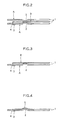
- FIG. 3 shows a second embodiment of the present invention and is a sectional enlarged view cut along the line (X-X) in FIG. 1;
- FIG.4 shows a third embodiment of the present invention and is a sectional enlarged view cut along the line (X-X) in FIG.1;
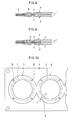
- FIG.5 is a plane view of the metal gasket showing a fourth embodiment of the present invention;
- FIG. 6 is a sectional enlarged view cut along the line (Y-Y) in FIG.5;
- FIG. 7 is a sectional enlarged view cut along the line (Z-Z) in FIG.5;
- FIG.8 is a sectional enlarged view of essential part of metal gasket showing a fifth embodiment of the present invention;
- FIG.9 is a sectional enlarged view of essential part of metal gasket showing a sixth embodiment of the present invention;
- FIG.10 is a plane view of essential part of metal gasket showing a tenth embodiment of the present invention; and
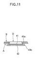
- FIG.11 is a sectional enlarged view cut along the line (X1 - X1) in FIG.10.
-
- The preferred embodiments of the present invention is such that, as shown in FIGS. 1 to 2, the metal gasket is constituted by two sheets of elastic metal substrates A, A which form
beads 2 on the peripheral portion ofcylinder openings 1 and an annular thin metal plate B which is a metal plate thinner than the substrate and which has an annular portion which surrounds the peripheral portion of the cylinder opening 1 with a predetermined width and which, moreover, is arranged between the substrates in opposition to the convex portions of thebead 2. - Each annular portion of the thin metal plate B is constituted so as to be integrally connected with an adjoining annular portion and, moreover, the thin metal plate B is fixed to an elastic metal substrate A, A, by inserting an
engaging portion 3 solidly projected from an outer periphery of an annular portion into aslit 4 formed on the elastic metal substrate A and folding it. - A first embodiment of the present invention is shown in FIGS. 1 to 2. FIG. 1 is a plane view of a metal gasket, and FIG. 2 is a sectional enlarged view cut along the line X-X.
- In the same drawings, the metal gasket is constituted by two sheets of elastic metal substrates A, A comprising a convex bead formed along each cylinder opening 1 of a multi-cylinder engine and having a thickness of 0.2 to 0.3 mm and a thin metal plate B which is a metal plate thinner than the elastic metal substrates A, A and has a thickness of 0.08 to 0.12 mm and has annular portions each of which surrounds the periphery of a cylinder opening with a predetermined width and, moreover, is arranged between the substrates A, A in opposition to the convex portion side of the beads of the substrates. Further, each annular portion of the thin metal plate B is constituted so as to be integrally connected to the adjoining annular portion.
- Each of the annular portions of the thin metal plate B is fixed to an elastic metal substrate A by inserting an
engaging portion 3 solidly projected from the outer periphery of the annular portion into theslit 4 formed on one elastic metal substrate A and folding it. - According to the constitution wherein the annular portions of the thin metal plate B are each fixed on a portion surrounding a cylinder opening 1 in the elastic metal substrates A, A, i.e. a cylinder opening in the metal gasket, the area of the gasket surrounding the
cylinder opening 1 can have a raised seal contact pressure at a time of fastening as it is thicker than the remainder of the gasket because of the presence of the metal thin plate B. - Further, by widening the metal thin plate B further than the bead outer side area, the seal contact pressure of the area surrounding the
cylinder opening 1 becomes uniform and, moreover, by fastening the bead by full compression, fatigue resistance of the bead is improved and the contact pressure drop is controlled so that a sealing performance with good durability and reliability can be achieved. - In FIG. 3, a second embodiment of the present invention is shown. The second embodiment omits one of the substrates A, A (the substrate A to which the metal thin plate B is not fixed, in Figure 2) from the elastic metal substrates A, A in the first embodiment, and the gasket is instead constituted by one sheet of the elastic metal substrate A and one sheet of the metal thin plate B.
- In FIG. 4, a third embodiment of the present invention is shown. The third embodiment omits one of the substrates A, A (the substrate A to which the metal thin plate B is not fixed in Figure 2) from among the elastic metal substrates A, A and is constituted by a
bead 5 which coordinates a part of the metal thin plate B fixed to the elastic metal substrate A with thebead 2 of the substrate A in the same direction. - In FIGS. 5 to 7, a fourth embodiment of the present invention is shown. Fig. 5 is a plane view of a metal gasket, FIG. 6 is a sectional enlarged view of the line cut along (Y-Y) in FIG. 5, and FIG. 7 is a sectional enlarged view of the line (Z-Z) in FIG. 5.
- In the fourth embodiment, a thin metal plate B is fixed to two sheets of the elastic metal substrates A, A by a coupling portion C by a press working and a caulking.
- That is, in the Y-Y line direction, as shown in FIG. 6, by the press working in the thickness direction of three sheets of the metal plates in the area outside of the
full bead 2, two sheets of the elastic metal substrates A, A and the thin metal plate B arranged between both metal substrates are deform-processed into convex portions comprisingtilting plates plate portions - In FIG. 8, a fifth embodiment of the present invention is shown. In the fifth embodiment, as means for fixing the thin metal plate B to the elastic metal substrate A, the thin metal plate B is fixed around the
cylinder opening 1 by a spot welding or a laser welding at one to six places in the area outside of afull bead 2 of the elastic metal substrate A. - In FIG. 9, a sixth embodiment of the present invention is shown. In the sixth embodiment, as means for fixing the thin metal plate B to the elastic metal substrate A, the thin metal plate B is fixed around the
cylinder opening 1 by an adhesive 7. The fixing by this adhesive may be across a full area or a partial area. - In FIGS. 10 to 11, a seventh embodiment of the present invention is shown. FIG. 10 is a partial plane view of a metal gasket, and FIG. 11 is a sectional enlarged view cut along the line (X1 - X1) in FIG. 10.
- In the seventh embodiment, one sheet of the elastic metal substrate A is fixed to the thin metal plate B by a coupling portion D formed by press working.
- That is, according to the seventh embodiment, the elastic metal substrate A and the thin metal plate B are deformed by the press in the thickness direction of the thin metal plate in the area outside of the
full bead 2, and aportion 43a bites into the elastic metal substrate A around a baseinner surface 41 of the thin metal plate B and is further deformed outside into the lateral direction and is formed in a state of biting into aportion 43b around apress base portion 42 of the elastic metal substrate A. - Thus, by the adjacent thin metal plates being deformed by adhering to each other and biting in this way, the thin metal plate B is fixed to the elastic metal substrate A.
- Each metal gasket of the second embodiment to seventh embodiment has the same function except that a fixing structure of the thin metal plate B to the elastic metal substrate A is different in relation to the first embodiment.
- As described above, according to the present invention, since the thin metal plate is fixed around the cylinder opening for the elastic metal substrate comprising the bead, the area around the cylinder opening is thicker by a layer thickness of the meal thin plate in contrast to other areas and, therefore, a seal contact pressure is raised.
- Further, by widening the thin metal plate B to extend to the area outside the bead, the seal contact pressure of the area surrounding the cylinder opening becomes uniform and, moreover, by fastening the bead by full compression, fatigue resistance of the bead is improved and the contact pressure drop is controlled so that a sealing performance of good durability and reliability can be provided.
Claims (9)
wherein the metal gasket comprises an elastic metal substrate (A) provided with a bead (2) on a cylinder opening peripheral portion; a portion arranged at a convex portion side of the bead (2) and constituted by a part of thin metal plate (B) which is thinner than the elastic metal substrate (A).
Applications Claiming Priority (2)
| Application Number | Priority Date | Filing Date | Title |
|---|---|---|---|
| JP2001085586 | 2001-03-23 | ||
| JP2001085586A JP4287069B2 (en) | 2001-03-23 | 2001-03-23 | Metal gasket |
Publications (3)
| Publication Number | Publication Date |
|---|---|
| EP1243820A2 true EP1243820A2 (en) | 2002-09-25 |
| EP1243820A3 EP1243820A3 (en) | 2004-01-14 |
| EP1243820B1 EP1243820B1 (en) | 2007-12-12 |
Family
ID=18941072
Family Applications (1)
| Application Number | Title | Priority Date | Filing Date |
|---|---|---|---|
| EP02252055A Revoked EP1243820B1 (en) | 2001-03-23 | 2002-03-22 | Metal gasket |
Country Status (4)
| Country | Link |
|---|---|
| US (1) | US6786490B2 (en) |
| EP (1) | EP1243820B1 (en) |
| JP (1) | JP4287069B2 (en) |
| KR (1) | KR100795707B1 (en) |
Cited By (4)
| Publication number | Priority date | Publication date | Assignee | Title |
|---|---|---|---|---|
| DE102004007034A1 (en) * | 2004-02-12 | 2005-07-14 | Daimlerchrysler Ag | Cylinder head seal for internal combustion engine, has external sheet metal plates joined to intermediate sheet layers by spot- or laser-welding |
| WO2007031127A1 (en) * | 2005-09-13 | 2007-03-22 | Federal-Mogul Sealing Systems Gmbh | Flat metal gaskets |
| DE102008006675A1 (en) * | 2008-01-30 | 2009-08-13 | Federal-Mogul Sealing Systems Gmbh | gasket |
| JP2016521837A (en) * | 2013-06-10 | 2016-07-25 | フェデラル−モーグル コーポレイション | Static gasket and method of construction |
Families Citing this family (20)
| Publication number | Priority date | Publication date | Assignee | Title |
|---|---|---|---|---|
| FR2827638B1 (en) * | 2001-07-23 | 2003-09-19 | Meillor Sa | CYLINDER HEAD GASKET COMPRISING AN EDGE-TO-EDGE STOPPER |
| KR20040031267A (en) * | 2002-10-04 | 2004-04-13 | 현대자동차주식회사 | Cylinder head gasket |
| KR20040046816A (en) * | 2002-11-28 | 2004-06-05 | 현대자동차주식회사 | Gasket for exhaust manifold |
| US6935635B2 (en) | 2002-12-12 | 2005-08-30 | Mccord Leakless Sealing Co. | Metal gasket |
| CN100366884C (en) * | 2002-12-12 | 2008-02-06 | 麦考德密封公司 | multilayer metal gasket |
| JP2005114053A (en) * | 2003-10-08 | 2005-04-28 | Ishikawa Gasket Co Ltd | Metal gasket |
| US20050189724A1 (en) * | 2004-02-26 | 2005-09-01 | Federal-Mogul Corporation | Metal gasket |
| DE102005020923A1 (en) * | 2005-05-04 | 2006-11-16 | Federal-Mogul Sealing Systems Gmbh | Flat gasket, in particular cylinder head gasket |
| DE102006014386A1 (en) * | 2006-03-29 | 2007-10-11 | Elringklinger Ag | Flat gasket, in particular cylinder head gasket |
| JP4137146B2 (en) * | 2006-07-21 | 2008-08-20 | トヨタ自動車株式会社 | gasket |
| JP4567722B2 (en) * | 2007-12-26 | 2010-10-20 | 石川ガスケット株式会社 | Metal laminated cylinder head gasket |
| WO2009152815A1 (en) * | 2008-06-21 | 2009-12-23 | Federal-Mogul Sealing Systems Gmbh | Flat seal |
| US20100032909A1 (en) * | 2008-08-06 | 2010-02-11 | Ford Global Technologies Llc | Engine Cylinder Head Gasket Assembly |
| US8245685B2 (en) * | 2009-06-26 | 2012-08-21 | Ford Global Technologies | Lubrication and sealing system for internal combustion engine |
| US8261702B2 (en) * | 2009-06-26 | 2012-09-11 | Ford Global Technologies | Internal combustion engine with direct cooling of cylinder components |
| JP5465038B2 (en) | 2010-02-22 | 2014-04-09 | 日本リークレス工業株式会社 | Manufacturing method of metal gasket for cylinder head and metal gasket for cylinder head |
| US20110204583A1 (en) * | 2010-02-24 | 2011-08-25 | Freudenberg-Nok General Partnership | Gasket Having Dual Bead Orientation On Rigid Carrier With Adjoining Gasket Material |
| US8474251B2 (en) | 2010-10-19 | 2013-07-02 | Ford Global Technologies, Llc | Cylinder head cooling system |
| US8752841B2 (en) * | 2012-05-18 | 2014-06-17 | Federal-Mogul Corporation | Gasket with a compression limiter |
| US9970548B2 (en) | 2013-03-14 | 2018-05-15 | Federal-Mogul Llc | Multi-layer gasket |
Citations (2)
| Publication number | Priority date | Publication date | Assignee | Title |
|---|---|---|---|---|
| JPS62115562U (en) | 1986-01-14 | 1987-07-22 | ||
| JPH026855U (en) | 1988-06-28 | 1990-01-17 |
Family Cites Families (6)
| Publication number | Priority date | Publication date | Assignee | Title |
|---|---|---|---|---|
| JPH01285645A (en) * | 1988-05-07 | 1989-11-16 | Nippon Gasket Kk | Metal gasket of cylinder head |
| DE3905056A1 (en) * | 1989-02-18 | 1990-08-23 | Bilstein August Gmbh Co Kg | COMPONENT FROM A MULTI-LAYERED FLAT MATERIAL CONSTRUCTION, IN PARTICULAR FOR MOTOR VEHICLES |
| JPH086805B2 (en) * | 1992-06-09 | 1996-01-29 | 日本メタルガスケット株式会社 | Metal gasket |
| US6044537A (en) * | 1994-12-16 | 2000-04-04 | Nippon Reinz Co., Ltd. | Method of making a metal gasket |
| JPH10184916A (en) * | 1996-12-20 | 1998-07-14 | Nippon Gasket Co Ltd | Metallic gasket |
| JP3738121B2 (en) * | 1997-11-07 | 2006-01-25 | 日本ガスケット株式会社 | Metal gasket |
-
2001
- 2001-03-23 JP JP2001085586A patent/JP4287069B2/en not_active Expired - Fee Related
-
2002
- 2002-03-21 US US10/103,588 patent/US6786490B2/en not_active Expired - Lifetime
- 2002-03-22 KR KR1020020015571A patent/KR100795707B1/en not_active Expired - Fee Related
- 2002-03-22 EP EP02252055A patent/EP1243820B1/en not_active Revoked
Patent Citations (2)
| Publication number | Priority date | Publication date | Assignee | Title |
|---|---|---|---|---|
| JPS62115562U (en) | 1986-01-14 | 1987-07-22 | ||
| JPH026855U (en) | 1988-06-28 | 1990-01-17 |
Cited By (6)
| Publication number | Priority date | Publication date | Assignee | Title |
|---|---|---|---|---|
| DE102004007034A1 (en) * | 2004-02-12 | 2005-07-14 | Daimlerchrysler Ag | Cylinder head seal for internal combustion engine, has external sheet metal plates joined to intermediate sheet layers by spot- or laser-welding |
| WO2007031127A1 (en) * | 2005-09-13 | 2007-03-22 | Federal-Mogul Sealing Systems Gmbh | Flat metal gaskets |
| US8246054B2 (en) | 2005-09-13 | 2012-08-21 | Federal-Mogul Sealing Systems Gmbh | Flat metal gaskets |
| DE102008006675A1 (en) * | 2008-01-30 | 2009-08-13 | Federal-Mogul Sealing Systems Gmbh | gasket |
| JP2016521837A (en) * | 2013-06-10 | 2016-07-25 | フェデラル−モーグル コーポレイション | Static gasket and method of construction |
| US10094329B2 (en) | 2013-06-10 | 2018-10-09 | Federal-Mogul Llc | Static gasket and method of construction thereof |
Also Published As
| Publication number | Publication date |
|---|---|
| US6786490B2 (en) | 2004-09-07 |
| US20020135135A1 (en) | 2002-09-26 |
| JP2002286141A (en) | 2002-10-03 |
| KR100795707B1 (en) | 2008-01-21 |
| JP4287069B2 (en) | 2009-07-01 |
| EP1243820A3 (en) | 2004-01-14 |
| EP1243820B1 (en) | 2007-12-12 |
| KR20020075289A (en) | 2002-10-04 |
Similar Documents
| Publication | Publication Date | Title |
|---|---|---|
| EP1243820B1 (en) | Metal gasket | |
| EP0574166B1 (en) | Metallic gasket | |
| EP0230804B2 (en) | Metallic gasket | |
| EP2188554B1 (en) | Metallic cylinder head gasket | |
| US20050189724A1 (en) | Metal gasket | |
| US6457724B2 (en) | Metallic gasket | |
| US7665741B2 (en) | Laminate-type gasket | |
| JPH08210507A (en) | Metal made gasket | |
| JPH10259873A (en) | Metal gasket | |
| JP3026081B2 (en) | Metal laminated gasket | |
| EP1573193A2 (en) | Metal gasket | |
| JPH10281289A (en) | Cylinder head gasket | |
| US6981703B2 (en) | Cylinder head gasket | |
| JP3314371B2 (en) | Metal gasket | |
| US20040212155A1 (en) | Cylinder head gasket with fold-over stopper | |
| JPH0842698A (en) | Metal gasket for sub-compartment diesel engine | |
| JPH05118443A (en) | Metal gasket | |
| JP2001032938A (en) | Metal gasket | |
| JP3688013B2 (en) | Cylinder head gasket | |
| JPH086806B2 (en) | Metal gasket | |
| JPH09229196A (en) | Metal gasket | |
| JPH06117542A (en) | Metal gasket | |
| JP2799627B2 (en) | Metal gasket mounting structure | |
| EP1544518A1 (en) | Cylinder head gasket | |
| JP3128094B2 (en) | Metal gasket |
Legal Events
| Date | Code | Title | Description |
|---|---|---|---|
| PUAI | Public reference made under article 153(3) epc to a published international application that has entered the european phase |
Free format text: ORIGINAL CODE: 0009012 |
|
| AK | Designated contracting states |
Kind code of ref document: A2 Designated state(s): AT BE CH CY DE DK ES FI FR GB GR IE IT LI LU MC NL PT SE TR |
|
| AX | Request for extension of the european patent |
Free format text: AL;LT;LV;MK;RO;SI |
|
| PUAL | Search report despatched |
Free format text: ORIGINAL CODE: 0009013 |
|
| AK | Designated contracting states |
Kind code of ref document: A3 Designated state(s): AT BE CH CY DE DK ES FI FR GB GR IE IT LI LU MC NL PT SE TR |
|
| AX | Request for extension of the european patent |
Extension state: AL LT LV MK RO SI |
|
| 17P | Request for examination filed |
Effective date: 20040625 |
|
| AKX | Designation fees paid |
Designated state(s): FR GB |
|
| 17Q | First examination report despatched |
Effective date: 20040920 |
|
| REG | Reference to a national code |
Ref country code: DE Ref legal event code: 8566 |
|
| GRAP | Despatch of communication of intention to grant a patent |
Free format text: ORIGINAL CODE: EPIDOSNIGR1 |
|
| GRAS | Grant fee paid |
Free format text: ORIGINAL CODE: EPIDOSNIGR3 |
|
| GRAA | (expected) grant |
Free format text: ORIGINAL CODE: 0009210 |
|
| AK | Designated contracting states |
Kind code of ref document: B1 Designated state(s): FR GB |
|
| REG | Reference to a national code |
Ref country code: GB Ref legal event code: FG4D |
|
| PLBI | Opposition filed |
Free format text: ORIGINAL CODE: 0009260 |
|
| 26 | Opposition filed |
Opponent name: FEDERAL-MOGUL SEALING SYSTEMS GMBH Effective date: 20080519 |
|
| ET | Fr: translation filed | ||
| PLAX | Notice of opposition and request to file observation + time limit sent |
Free format text: ORIGINAL CODE: EPIDOSNOBS2 |
|
| PLBB | Reply of patent proprietor to notice(s) of opposition received |
Free format text: ORIGINAL CODE: EPIDOSNOBS3 |
|
| PGFP | Annual fee paid to national office [announced via postgrant information from national office to epo] |
Ref country code: GB Payment date: 20090325 Year of fee payment: 8 |
|
| PGFP | Annual fee paid to national office [announced via postgrant information from national office to epo] |
Ref country code: FR Payment date: 20090330 Year of fee payment: 8 |
|
| RDAF | Communication despatched that patent is revoked |
Free format text: ORIGINAL CODE: EPIDOSNREV1 |
|
| RDAG | Patent revoked |
Free format text: ORIGINAL CODE: 0009271 |
|
| STAA | Information on the status of an ep patent application or granted ep patent |
Free format text: STATUS: PATENT REVOKED |
|
| 27W | Patent revoked |
Effective date: 20090921 |
|
| GBPR | Gb: patent revoked under art. 102 of the ep convention designating the uk as contracting state |
Effective date: 20090921 |