EP1243525A2 - Container for long-term transport comprising highly insulating components - Google Patents
Container for long-term transport comprising highly insulating components Download PDFInfo
- Publication number
- EP1243525A2 EP1243525A2 EP01250343A EP01250343A EP1243525A2 EP 1243525 A2 EP1243525 A2 EP 1243525A2 EP 01250343 A EP01250343 A EP 01250343A EP 01250343 A EP01250343 A EP 01250343A EP 1243525 A2 EP1243525 A2 EP 1243525A2
- Authority
- EP
- European Patent Office
- Prior art keywords
- container
- insulating
- outer tube
- jacket
- inner tube
- Prior art date
- Legal status (The legal status is an assumption and is not a legal conclusion. Google has not performed a legal analysis and makes no representation as to the accuracy of the status listed.)
- Granted
Links
Images


Classifications
-
- F—MECHANICAL ENGINEERING; LIGHTING; HEATING; WEAPONS; BLASTING
- F17—STORING OR DISTRIBUTING GASES OR LIQUIDS
- F17C—VESSELS FOR CONTAINING OR STORING COMPRESSED, LIQUEFIED OR SOLIDIFIED GASES; FIXED-CAPACITY GAS-HOLDERS; FILLING VESSELS WITH, OR DISCHARGING FROM VESSELS, COMPRESSED, LIQUEFIED, OR SOLIDIFIED GASES
- F17C3/00—Vessels not under pressure
- F17C3/02—Vessels not under pressure with provision for thermal insulation
- F17C3/04—Vessels not under pressure with provision for thermal insulation by insulating layers
-
- A—HUMAN NECESSITIES
- A47—FURNITURE; DOMESTIC ARTICLES OR APPLIANCES; COFFEE MILLS; SPICE MILLS; SUCTION CLEANERS IN GENERAL
- A47J—KITCHEN EQUIPMENT; COFFEE MILLS; SPICE MILLS; APPARATUS FOR MAKING BEVERAGES
- A47J41/00—Thermally-insulated vessels, e.g. flasks, jugs, jars
- A47J41/0038—Thermally-insulated vessels, e.g. flasks, jugs, jars comprising additional heating or cooling means, i.e. use of thermal energy in addition to stored material
- A47J41/0044—Thermally-insulated vessels, e.g. flasks, jugs, jars comprising additional heating or cooling means, i.e. use of thermal energy in addition to stored material comprising heat or cold storing elements or material, i.e. energy transfer within the vessel
-
- B—PERFORMING OPERATIONS; TRANSPORTING
- B65—CONVEYING; PACKING; STORING; HANDLING THIN OR FILAMENTARY MATERIAL
- B65D—CONTAINERS FOR STORAGE OR TRANSPORT OF ARTICLES OR MATERIALS, e.g. BAGS, BARRELS, BOTTLES, BOXES, CANS, CARTONS, CRATES, DRUMS, JARS, TANKS, HOPPERS, FORWARDING CONTAINERS; ACCESSORIES, CLOSURES, OR FITTINGS THEREFOR; PACKAGING ELEMENTS; PACKAGES
- B65D81/00—Containers, packaging elements, or packages, for contents presenting particular transport or storage problems, or adapted to be used for non-packaging purposes after removal of contents
- B65D81/18—Containers, packaging elements, or packages, for contents presenting particular transport or storage problems, or adapted to be used for non-packaging purposes after removal of contents providing specific environment for contents, e.g. temperature above or below ambient
-
- B—PERFORMING OPERATIONS; TRANSPORTING
- B65—CONVEYING; PACKING; STORING; HANDLING THIN OR FILAMENTARY MATERIAL
- B65D—CONTAINERS FOR STORAGE OR TRANSPORT OF ARTICLES OR MATERIALS, e.g. BAGS, BARRELS, BOTTLES, BOXES, CANS, CARTONS, CRATES, DRUMS, JARS, TANKS, HOPPERS, FORWARDING CONTAINERS; ACCESSORIES, CLOSURES, OR FITTINGS THEREFOR; PACKAGING ELEMENTS; PACKAGES
- B65D81/00—Containers, packaging elements, or packages, for contents presenting particular transport or storage problems, or adapted to be used for non-packaging purposes after removal of contents
- B65D81/38—Containers, packaging elements, or packages, for contents presenting particular transport or storage problems, or adapted to be used for non-packaging purposes after removal of contents with thermal insulation
- B65D81/3802—Containers, packaging elements, or packages, for contents presenting particular transport or storage problems, or adapted to be used for non-packaging purposes after removal of contents with thermal insulation rigid container in the form of a barrel or vat
- B65D81/3806—Containers, packaging elements, or packages, for contents presenting particular transport or storage problems, or adapted to be used for non-packaging purposes after removal of contents with thermal insulation rigid container in the form of a barrel or vat formed with double walls, i.e. hollow
-
- F—MECHANICAL ENGINEERING; LIGHTING; HEATING; WEAPONS; BLASTING
- F17—STORING OR DISTRIBUTING GASES OR LIQUIDS
- F17C—VESSELS FOR CONTAINING OR STORING COMPRESSED, LIQUEFIED OR SOLIDIFIED GASES; FIXED-CAPACITY GAS-HOLDERS; FILLING VESSELS WITH, OR DISCHARGING FROM VESSELS, COMPRESSED, LIQUEFIED, OR SOLIDIFIED GASES
- F17C13/00—Details of vessels or of the filling or discharging of vessels
- F17C13/001—Thermal insulation specially adapted for cryogenic vessels
-
- F—MECHANICAL ENGINEERING; LIGHTING; HEATING; WEAPONS; BLASTING
- F17—STORING OR DISTRIBUTING GASES OR LIQUIDS
- F17C—VESSELS FOR CONTAINING OR STORING COMPRESSED, LIQUEFIED OR SOLIDIFIED GASES; FIXED-CAPACITY GAS-HOLDERS; FILLING VESSELS WITH, OR DISCHARGING FROM VESSELS, COMPRESSED, LIQUEFIED, OR SOLIDIFIED GASES
- F17C3/00—Vessels not under pressure
- F17C3/02—Vessels not under pressure with provision for thermal insulation
- F17C3/04—Vessels not under pressure with provision for thermal insulation by insulating layers
- F17C3/06—Vessels not under pressure with provision for thermal insulation by insulating layers on the inner surface, i.e. in contact with the stored fluid
-
- F—MECHANICAL ENGINEERING; LIGHTING; HEATING; WEAPONS; BLASTING
- F17—STORING OR DISTRIBUTING GASES OR LIQUIDS
- F17C—VESSELS FOR CONTAINING OR STORING COMPRESSED, LIQUEFIED OR SOLIDIFIED GASES; FIXED-CAPACITY GAS-HOLDERS; FILLING VESSELS WITH, OR DISCHARGING FROM VESSELS, COMPRESSED, LIQUEFIED, OR SOLIDIFIED GASES
- F17C3/00—Vessels not under pressure
- F17C3/02—Vessels not under pressure with provision for thermal insulation
- F17C3/08—Vessels not under pressure with provision for thermal insulation by vacuum spaces, e.g. Dewar flask
-
- F—MECHANICAL ENGINEERING; LIGHTING; HEATING; WEAPONS; BLASTING
- F25—REFRIGERATION OR COOLING; COMBINED HEATING AND REFRIGERATION SYSTEMS; HEAT PUMP SYSTEMS; MANUFACTURE OR STORAGE OF ICE; LIQUEFACTION SOLIDIFICATION OF GASES
- F25D—REFRIGERATORS; COLD ROOMS; ICE-BOXES; COOLING OR FREEZING APPARATUS NOT OTHERWISE PROVIDED FOR
- F25D3/00—Devices using other cold materials; Devices using cold-storage bodies
- F25D3/02—Devices using other cold materials; Devices using cold-storage bodies using ice, e.g. ice-boxes
- F25D3/06—Movable containers
-
- F—MECHANICAL ENGINEERING; LIGHTING; HEATING; WEAPONS; BLASTING
- F17—STORING OR DISTRIBUTING GASES OR LIQUIDS
- F17C—VESSELS FOR CONTAINING OR STORING COMPRESSED, LIQUEFIED OR SOLIDIFIED GASES; FIXED-CAPACITY GAS-HOLDERS; FILLING VESSELS WITH, OR DISCHARGING FROM VESSELS, COMPRESSED, LIQUEFIED, OR SOLIDIFIED GASES
- F17C2203/00—Vessel construction, in particular walls or details thereof
- F17C2203/06—Materials for walls or layers thereof; Properties or structures of walls or their materials
- F17C2203/0602—Wall structures; Special features thereof
- F17C2203/0612—Wall structures
- F17C2203/0626—Multiple walls
- F17C2203/0629—Two walls
-
- F—MECHANICAL ENGINEERING; LIGHTING; HEATING; WEAPONS; BLASTING
- F25—REFRIGERATION OR COOLING; COMBINED HEATING AND REFRIGERATION SYSTEMS; HEAT PUMP SYSTEMS; MANUFACTURE OR STORAGE OF ICE; LIQUEFACTION SOLIDIFICATION OF GASES
- F25D—REFRIGERATORS; COLD ROOMS; ICE-BOXES; COOLING OR FREEZING APPARATUS NOT OTHERWISE PROVIDED FOR
- F25D2201/00—Insulation
- F25D2201/10—Insulation with respect to heat
- F25D2201/12—Insulation with respect to heat using an insulating packing material
- F25D2201/128—Insulation with respect to heat using an insulating packing material of foil type
- F25D2201/1282—Insulation with respect to heat using an insulating packing material of foil type with reflective foils
-
- F—MECHANICAL ENGINEERING; LIGHTING; HEATING; WEAPONS; BLASTING
- F25—REFRIGERATION OR COOLING; COMBINED HEATING AND REFRIGERATION SYSTEMS; HEAT PUMP SYSTEMS; MANUFACTURE OR STORAGE OF ICE; LIQUEFACTION SOLIDIFICATION OF GASES
- F25D—REFRIGERATORS; COLD ROOMS; ICE-BOXES; COOLING OR FREEZING APPARATUS NOT OTHERWISE PROVIDED FOR
- F25D2201/00—Insulation
- F25D2201/10—Insulation with respect to heat
- F25D2201/14—Insulation with respect to heat using subatmospheric pressure
-
- F—MECHANICAL ENGINEERING; LIGHTING; HEATING; WEAPONS; BLASTING
- F25—REFRIGERATION OR COOLING; COMBINED HEATING AND REFRIGERATION SYSTEMS; HEAT PUMP SYSTEMS; MANUFACTURE OR STORAGE OF ICE; LIQUEFACTION SOLIDIFICATION OF GASES
- F25D—REFRIGERATORS; COLD ROOMS; ICE-BOXES; COOLING OR FREEZING APPARATUS NOT OTHERWISE PROVIDED FOR
- F25D2331/00—Details or arrangements of other cooling or freezing apparatus not provided for in other groups of this subclass
- F25D2331/80—Type of cooled receptacles
- F25D2331/804—Boxes
-
- F—MECHANICAL ENGINEERING; LIGHTING; HEATING; WEAPONS; BLASTING
- F25—REFRIGERATION OR COOLING; COMBINED HEATING AND REFRIGERATION SYSTEMS; HEAT PUMP SYSTEMS; MANUFACTURE OR STORAGE OF ICE; LIQUEFACTION SOLIDIFICATION OF GASES
- F25D—REFRIGERATORS; COLD ROOMS; ICE-BOXES; COOLING OR FREEZING APPARATUS NOT OTHERWISE PROVIDED FOR
- F25D3/00—Devices using other cold materials; Devices using cold-storage bodies
Definitions
- the invention relates to an interchangeable container with vacuum insulation, Energy storage, one or more storage rooms, various highly insulating components and a temperature measurement, storage and data transmission system.
- Containers are known for the transport of fresh fish, for food, living organs, microorganisms and other materials that have to be stored and / or transported in a certain temperature range.
- EP 209 003 A2 describes a double-walled insulated container for storing low-boiling liquefied gases.
- the container has an inner and an outer container, the inner container being connected to the opening of the outer container by a so-called neck tube.
- the space between the inner and outer container is filled with insulation, which is usually made of foam.
- a similar container is described in DE-OS 29 26 646, in which the inner container is surrounded by vacuum insulation, the vacuum insulation being arranged in a separate container enclosing the inner container but not touching the outer container.
- the containers described in the two cited documents have an elongated area at an acute angle as a transition from the outer container to the inner container, in order to keep thermal bridges and the associated temperature losses as low as possible.
- the upper part of the insulation which extends towards the opening takes up the largest part of the interior. Accordingly, only the inner container provided for the storage of certain materials can be made small. Conventional containers therefore have a very unfavorable ratio of the inner storage space to the space surrounded by the outer skin.
- a thick-walled sleeve-shaped container is also known from DE 44 38 141 A1 (column 7, line 52), which can be screwed onto one another in a stackable manner with a further sleeve-shaped container using a screwing device.
- the container is equipped with a so-called temperature accumulator ", which is inserted into the lid and in the bottom as a flangeable and exchangeable plate element. The lid and the bottom of said container are to be screwed into it.
- the container according to this invention is in the upper region of The lid closing device is used to replace a tempering battery without opening the container, so that when the batteries are replaced, the inside temperature of the container is not impaired
- a cooling battery in a lid and / or in a lower housing part has a container for food according to EP 0 153 975 A1, the cooling battery or a cooling medium being either exchangeable or permanently welded.
- a container for the storage of deep-frozen material is known from EP 178 337 A1.
- the container consists of an outer and an inner vessel, the latter being insertable into the outer vessel via a bottom opening and the outer vessel and the inner vessel each being hermetically sealed with a foot part.
- EP 1 006 058 A1 discloses a container with a compact wall made of heat-insulating material, in which the surface of the sealing edge areas between the cover and the container body is provided with a sealing compound to prevent heat from flowing out.
- a wide range within the state of the art are bottle-shaped smaller containers with vacuum insulation.
- the inner container is freely suspended in the outer container at the upper edge of the outer container.
- the inner bottle-shaped containers are also freely suspended on the upper edge of the outer container, but are provided with a support, as described, for example, in EP-0 109 262 A1.
- Such bottle-shaped containers are only very limited and can then only be used for the storage of very small quantities. Due to the free-hanging fastening of the inner container at the edge of the outer container, it is not possible to fill the storage rooms with a larger storage weight, even with larger dimensions of the containers. In addition, you are always bound to a round or almost round shape. From DE 40 29 405 A 1, a molded body for thermal insulation evacuated in the interior is known, the covering of which consists of a gas- and watertight and metal-free film.
- transition areas at the connections between the inner and outer wall or inner and outer container are equally problematic.
- good insulation materials such as polyurethane, styrofoam, cork sheets and the like, but also vacuum
- all of the containers described are not suitable for storing substances that are to be stored, for example, for the storage of human skin at temperatures in a range of approximately -80 ° C. keep for a period> 36 - 40 hours.
- all containers are relatively heavy and thick-walled and therefore made of material-intensive.
- Transport containers with vacuum insulation offered in practice have, for example, 2 mm thick inner and outer walls and achieve a service life of only 36 hours at a desired storage temperature in the range of -80 ° C.
- the object of the invention is to overcome the disadvantages of the known and insulating containers Eliminate components or at least minimize them so that downtimes for containers, for example for the transport and storage of cryogenic biological samples, Organs, cultures and the like in a temperature range from -90 ° C to -75 ° C of> 50 Hours, preferably> 100 hours, can be achieved.
- the recharging of energy storage should only become necessary after> 100 hours.
- the usage Liquid nitrogen should generally be excluded.
- the alternatively used foil vacuum insulation as a highly effective heat shield is mostly powder or filler-based and of disc, plate, ring, pot, cylinder, hollow cylinder or circular segment shape and is preferably arranged in foam in wall elements and constructions, with the foil Vacuum insulation in areas of potential thermal bridges is arranged one behind the other or one above the other.
- the high-vacuum super insulation consists of a double-wall system with a closed hollow body formed from an approximately parallel outer jacket and an inner jacket with an internal atmosphere evacuated up to the high vacuum area.
- the inner jacket is designed to be thinner all around at both ends and has elongated and single or multiple bent ends which are welded to the outer jacket in a vacuum-tight manner.
- the ends of the inner and / or outer jacket have any shape that extends the thermal path. Beadings molded into the inner and / or outer jacket lead to stabilization against implosion and thus to a reduction in wall thicknesses and ensure a further elastic compensation between the inner and outer jacket.
- the dimensionally stable foam insulation is placed in shell-shaped coverings, which are made of stainless steel sheet or plastic, for example, and is used to lock and protect inserted insulating components of various shapes, as well as the mechanical stability of enclosing, connecting or sealing constructions, and to avoid or reduce them thermal bridges.
- the high vacuum super insulation in hollow bodies with support structures in enveloping, connecting or sealing constructions consists of a casing with an interior in which support structures are arranged.
- the support structures partially or almost completely fill the interior of the hollow body in one or more layers next to one another and / or one above the other.
- the support structures consist, on the one hand, of circular or polygonal cells, which are staggered one above the other and / or next to one another in several layers such that the cell walls arranged one above the other only touch one another in a punctiform manner.
- the support structure made of circular or polygonal cells is a vertically cell-shaped material, which consists for example of coated paper, glass, ceramic or plastic structures.
- the support structures are designed in the form of rings, for example in the form of a tube (torus) or as a full ring and are arranged in a ring shape in the interior of the hollow body, preferably in a plurality of rings next to one another.
- the tubular or full-ring support structures are made of glass fiber reinforced plastic.
- insulating components are proposed, the evacuation zones with support structures arranged in them.
- These insulating components are for the particularly critical areas of interchangeable containers, e.g. Cover, Insulation or ring-shaped edge, foot part and connecting elements for stacking several containers one above the other. They are in the walls of the lid, base and Connection element and the insulation ring arranged.
- the walls are preferably made made of plastic.
- an interchangeable temperature-controlled container with a closed hollow body formed from approximately parallel mutually extending outer jacket and inner jacket as a jacket with an inner atmosphere evacuated up to the high vacuum region, a foot part closing an opening of the hollow body and a cover closing another opening of the hollow body, or these further opening of the hollow body can be closed by an edge area with an internal cover and the changeable temperature-controlled container has one or more energy stores and a storage room.
- the hollow body mentioned is preferably of tubular shape and forms a hollow cylinder, the outer shell of which is an outer tube and the inner shell of which is an inner tube.
- the outer tube and the inner tube are hermetically connected to one another at the respective end faces.
- circumferential formations or neckings are formed on the inner tube and / or the outer tube, which are designed with at least two degrees of freedom as spring or expansion elements.
- the deformations or neckings compensate for the material deformation that occurs as a result of the differences in the temperatures prevailing on the inner tube and on the outer tube.
- the formations or necklines of the inner tube and / or outer tube form an imaginary circumferential annular chamber, which has the shape of a body which, when a flat figure moves along a closed curve - for example by its rotation about the axis which is in the plane of this figure lies and does not cut - results.
- the circumferential formations or neckings on the end faces of the inner tube and the outer tube have different shapes, preferably they are double-sinusoidal or S-shaped or circular-arc-shaped.
- the formations or neckings extend the heat path between the inner tube and the outer tube.
- the heat transfer is also reduced via the formations or neckings in that the material thicknesses of these are at least a quarter less than the material thicknesses of the inner and outer tubes.
- the foot part which closes an opening of the hollow body and the edge region which closes the other opening of the hollow body is held by stabilizing elements and / or foaming adhesives which run around the respective end faces of the hollow body and are directed inwards and / or outwards.
- the stabilizing elements are advantageously designed as beads.
- the inner tube is equipped with a super insulation winding, consisting of spacers, radiation-reflecting materials and the optional introduction of a chemical getter or an adsorption material.
- the changeable temperature-controlled container is - as already stated - provided in the upper area with a closing edge with an internal lid and in the lower area with a foot part.
- These parts closing the hollow body on its end faces consist of highly insulating foams which are encased in a shell. Further highly insulating components are arranged within the respective shells with highly insulating foam within the closing edge, the lid and the foot part.
- the changeable temperature-controlled container provides for a double bottom, as described below, to be arranged at the lower end opening of the hollow body.
- the double bottom consists of preformed cambered bottom plates, a bottom plate closing the inner jacket and a bottom plate closing the outer jacket, so that the space between the two bottom plates is connected to the space between the inner jacket and the outer jacket of the hollow body and can be evacuated in one operation.
- the bottom plates are flanged at a right angle in an arc shape, are provided with a defined curvature towards their center and are preferably made of sheet steel and, after welding to the outer jacket or to the inner jacket, are designed with at least two degrees of freedom as a spring or expansion element. All-round beads are molded into the sheet metal bottoms as additional spring or expansion elements.
- the connection of the inner jacket with the one floor panel and the other connection of the outer panel with the outer jacket is vacuum-tight.
- the sheets have a material thickness that is at least a quarter less than the material thickness of the outside and Inner sheath.
- Supporting and spacing support structures are arranged between the two sheets. During evacuation, the two metal sheets bulge towards each other and are - as described above - spaced apart by support structures.
- a conventional evacuation opening and a container for storing and dispensing getter material are provided on the outer floor panel.
- the bottom region of the container according to the invention is encased with a foot part, consisting of a plastic shell with dimensionally stable foam plastic arranged on the inside. The foot part essentially serves to protect the outer container bottom and the connection points between the outer jacket and the corresponding outer bottom.
- the interchangeable temperature-controlled container is specially designed for the transport of Larger units are stacked on top of each other, so that several containers share a common storage space form, and are connected by one or more connecting elements.
- the fasteners are just like the foot part and closing edge area on the respective End faces of the hollow body on circumferential, inward and / or outward stabilizing elements locked and / or held by foaming glue.
- the insulating components to be proposed are surrounded by a one-part or multi-part hard plastic shell, and various insulating bodies are embedded in dimensionally stable plastic foam inside the same.
- An insulating body is of flat-cylindrical shape and is preferably used in the lid and in the base part of an interchangeable container.
- the insulating body consists of a cylindrical jacket, the upper and lower opening of which are closed by preformed convex sheets.
- the cylindrical jacket and the preformed cambered sheets are made of stainless steel sheet, the material thickness of which is dimensioned at least a quarter less than the usual walls of a vacuum-insulated, interchangeable temperature-controlled container.
- the two sheets and the jacket are provided in their edge regions with circumferential formations or neckings, which are designed with at least two degrees of freedom as spring or expansion elements.
- the two sheets are provided with all-round beads.
- the cambered sheets are flanged at their edges and welded to the jacket in a vacuum-tight manner, so that a flat hollow body is created.
- the dimensioning of this hollow body is chosen such that a cover or a foot part is almost completely filled in its largest areal extent. This minimizes or excludes thermal bridges as far as possible.
- the interior of such a hollow body is partially or almost completely filled with support structures and, after the interior has been evacuated, is an essentially finished insulating body.
- the support structures have the task of transferring forces from the one sheet to the opposite sheet, and their structure is selected such that they are staggered in several layers one above the other.
- Perforated films and / or evacuation drains preferably glass fleece layers, are inserted between one or more layers of support structures.
- the arrangement of the support structures can be selected to be circular, ring-shaped, segment-shaped or punctiform, or completely filling the interior of a hollow body.
- Such an insulating body is positioned in a cover or foot part of a container during manufacture such that the wall of the insulating body does not touch the aforementioned hard plastic shell of the cover or foot part.
- the insulating body is foamed into the plastic shells mentioned and thus locked in place.
- One or more layers of a reflective material are additionally inserted into the cover or the foot part in order to achieve additional radiation shielding from the outside atmosphere.
- the reflection material can also be incorporated into the hard plastic shell mentioned. After the lid and foot section have been foamed, they are closed with additional parts of precisely fitting hard plastic shells and the seams are sealed. It is within the scope of the invention, for example, to manufacture the foot part to fit the casing of the container, so that only a seal takes place between the edge of the foot part and the container wall.
- Another insulating body is again proposed for the lid and base.
- This insulating body according to the invention is not placed separately in the lid and foot part as a separate insulating body, but is specially constructed with the lid and foot part.
- the following layers of different materials are glued or sealed to one another with an appropriate shape.
- An outer, curable cover layer which preferably consists of epoxy resin with an inserted radiation-reflecting film, is followed by several layers of laminate layers.
- the layered lamination is preferably carried out using glass silk and epoxy resin.
- larger cavities between the individual layers are filled with plastic.
- Metal-coated plastic foils preferably aluminum composite foil or metal foils, are alternately embedded in layers with glass fleece layers so that the introduction of support structures in the interior of the lid or the foot part creates an evacuable cavity surrounded by diffusion-proof foil.
- Support structures mentioned are arranged within the insulating body thus created.
- Several layers of glass fleece are embedded between them.
- Glass fleece layers are also provided according to the invention for completely encasing the support structures. The quality of the glass fleece layers is selected so that they also serve as evacuation drainages.
- Perforated reflective foils are preferably arranged between the layers of support structures.
- the interior of this insulating body is evacuated in a conventional manner via an evacuation nozzle in a manner known per se.
- the evacuation nozzle expediently leads into the upper middle lid area, so that it can be evacuated again from the outside after several years after the vacuum has dropped.
- the insulating body is enclosed in a dimensionally stable manner with the further construction of the cover or base part by further laminate layers and / or foamed-in plastic and sealed with a sealing cover layer.
- the insulating body with a tubular jacket and cambered sheets and the insulating body with a hollow cylindrical interior - as described above - have circumferential formations or neckings directly in the area of their seams or weld seams, which are designed with at least two degrees of freedom as a spring or expansion element. Regarding the formations or neckings, reference is made to the preceding explanations.
- connection is made with a connecting element.
- This connection represents a particularly critical zone.
- a further embodiment of an insulating body is introduced into the connecting element, which is double-tubular in shape and for a connecting element and / or for an annular edge of the container, in which a lid for closing the container inserted, is used.
- the insulating body of double-tubular shape consists of nested cylindrical inner tube and cylindrical outer tube, which are vacuum-tightly connected at their respective end faces by a weld seam and thus form a hollow cylindrical body, the evacuated hollow cylindrical interior of which partially or almost completely fills the interior with support structures in order to compensate for forces between Transfer inner tube and outer tube.
- Energy stores are located in the interior of the changeable temperature-controlled container sensory storage, latent storage or chemical storage.
- This energy storage consist of different geometric shapes and are in the area of the lid as a single or multi-layer plate element and / or in the area of the floor also as a single or multilayer plate element and / or, depending on the materials to be stored, in the storage room of the changeable temperable container as a cylindrical, hollow cylindrical, plate, segment or sector-shaped body.
- the changeable temperature-controllable container has a temperature measuring device known per se, the data of which, as well as details of the location, object, temperature profile and other information, can be called up, stored and reset at any time in the usual manner. A connection of this data acquisition and evaluation of several containers is provided. Since the materials to be transported with the containers according to the invention are mostly very valuable goods - for example for organ transplants - it makes sense to use the latest devices - for example chip cards with a temperature recording function.
- the chip card with sensor, memory, battery and a time-determining element can serve as a passport for the transported goods.
- Interchangeable temperature-controlled containers manufactured in this way ensure that the evacuation room of the insulating bodies in the lid, foot section, insulation ring and connecting element has a service life of at least 5 years and ensure that the heat-exchangeable container has a service life of around 140 hours in a temperature range from -90 ° C to -75 ° C when used accordingly energy storage. In other temperature ranges, the service life changes accordingly.
- the invention is explained and described in more detail below with reference to the exemplary embodiments shown in the drawings. The features that can be gathered from the drawings and the description can be used in other embodiments of the invention individually or in combination in any combination.
- FIG. 1 shows a transport container 1, consisting of a casing 30 with cover 12 and Base part 9.
- a storage space 17 into which energy stores 3 corresponding to cover 12 and base part 9 , which in the present exemplary embodiment are cooled to approximately minus 120 ° C. before being introduced into the container, protrude.
- cover 12 In the upper part of the transport container 1 , its edge is surrounded by an annular edge or insulation ring 11 .
- the cover 12 is embedded in the annular edge or insulation ring 11 .
- the annular rim or insulation ring 11, the foot part 9 and the cover 12 each consist of a plastic shell and one or more insulation materials known per se, preferably of foam.
- 10 foil vacuum insulations in the form of disks, plates, rings, pots, cylinders, hollow cylinders or circular segments are arranged as insulating components. It is within the scope of the invention to design these insulating components 10 as vacuum or high-vacuum containers made of plastic, glass, ceramic and / or metal, in the evacuation zones of which support structures - as will be described below - and reflection materials are arranged.
- the insulating components 10 with vacuum are foamed into an insulating material within the plastic shell of the cover 12 and the base part 9 and optionally also in the insulating ring 11 .
- the container has handles 31 on its outer sides and the lid 12 has a handle 32 and is provided with closing devices and securing devices.
- the casing 30 consists of a tubular double-walled body, which is preferably made of stainless steel sheet in this example.
- the tubular double-walled body is provided on the inner wall of the container or the inner tube 15 with a super insulation winding, which consists of a spacer in conjunction with a radiation-reflecting film. It is also possible to introduce a chemical getter or an adsorption material.
- 2 and 3 each show partial sections through an outer tube 33 with evacuation socket 34 and an inner tube 15 or a container inner wall as components of the casing 30.
- the outer tube 33 has circumferential beads 35 which are curved outwards in several areas.
- the inner tube 15 has double-sinusoidal or S-shaped grooves 36 which face outwards in each case.
- FIG. 4 shows a container edge area, consisting of a casing 37 with an inner vessel 38 and an outer casing 39. Inside the casing 37 , an insulating material 40 is embedded, which mostly consists of polyurethane, polystyrene, glass wool, cork sheets or other insulating materials.
- the use of vacuum within shells 37 is also known. When using a vacuum for insulation, stainless steel sheets or aluminum alloys are used in practice for the inner and outer sheathing of at least 2 mm material thickness.
- the inner tube 15 or the inner wall of the container consists of a maximum of 0.6 mm thick stainless steel sheet and is in the upper and lower transition area - wherein only the upper transition area is shown in FIG. 5 - to the outer tube 33 and connecting to it with one around the ends of the inner tube 15 or the inner wall of the container is provided with a groove 36 which extends in an S-shaped manner in the radial direction, the outermost leg 42 preferably extending in relation to the S-shaped bends and additionally being provided with a lip 43 .
- the outer tube 33 at the end runs slightly inwards chamfered to the lip 43 of the double-sinus or S-shaped groove 36 and is welded to the inner tube 15 at the seam 44 during the production of the casing 30 .
- the connection of inner tube 15 and outer tube 33 takes place at the opening of the tubular double-walled body opposite the cover 12 or the annular edge 11 .
- the outer tube 33 is arranged around the inner tube 15 in such a way that it forms a hermetically sealed hollow cylinder, in which a high-vacuum superinsulation 13 in the range of -4 10 -4 Pa is generated via an evacuation nozzle 34 and thus an operational service life of the Vacuum and thus the super isolator is guaranteed for 5 years.
- the vacuum is stabilized by gettingtering or introducing an absorber.
- Inner tubes 15 and outer tubes 33 connected in the manner described are resiliently connected to one another by the double-sinus or S-shaped groove 36 described here.
- the S-shaped groove 36 is a spring or expansion element having at least two degrees of freedom and, according to the invention, can have any shape that extends the thermal path. It has already been mentioned that the inner tube 15 has a wall thickness of 0.6 mm. In the area of the double sinusoidal or S-shaped groove 36 , the material thickness is deliberately reduced to a maximum of 0.4 mm by the expansion or extension of the tube material. This significantly reduces the heat flow, the overall heat path being considerably lengthened due to the geometry of the S-shaped groove 36 .
- This special design reduces thermal bridges to a minimum.
- the entire container edge area as shown in FIG. 5, is surrounded by an all-round annular edge or an insulation ring 11, which is pressed over or under over the container edge area via stabilizing elements - here in the form of inwardly and / or outwardly directed beads 45 Using special shapes directly from the edge of the container made of insulating foam.
- the annular rim or insulation ring 11 is cast in a shell and a section along the inner tube 15 or the inner wall of the container via the S-shaped groove 36 and along the outer elongated leg 42 , the lip 43 and in turn downwards over a section of the outer tube 33 and is locked on a bead 45 of the outer tube 33 .
- the resulting overlapping edge 46 provides additional insulation and is locked in place.
- the ring-shaped edge or insulation ring 11 is fixed and well sealed around the upper edge of the container.
- the overlapping edge 46 which runs along the outer tube 33 as described, reduces thermal bridges in connection with the material tapering in the outer tube 33, which is accompanied by the all-round bead 45 .
- the foot part 9 is fastened around the lower edge of the container.
- the foot part 9 is made in a compact design from a switched-on insulating material, provided with feet and / or rollers and additionally serves to accommodate one or more known energy stores 3.
- Inside the switched-on insulating material of the foot part 9 are like in the cover 12 and the insulation ring 11 also insulating components 10 arranged in a foamed manner.
- the cover 12 is also made of a switched-on insulating material and is embedded in the ring-shaped edge or insulation ring 11 in a tight and well-sealing manner.
- One or more energy stores 3 are likewise arranged on the cover 12 in the interior of the transport container 1 as a counterpart to the energy store 3 in the foot part 9 .
- Sensory stores, latent stores or chemical stores, each of which can be recharged, are used as energy stores 3 .
- the insulation ring 11 is provided with a known temperature measurement, storage and data transmission device (not shown in more detail in the figures) and has one or more closing or shut-off devices. In order to prevent freezing of the closing elements, corresponding ventilation slots or condensate drains are incorporated in the insulation ring 11 .
- a transport container 1, essentially as described in Example 1, has, according to the invention, an annular edge 48 which rests tightly and sealingly on the inner tube 15 or inner wall of the container, on the leg 42 and the lip 43 and in the region of the double-sinus-shaped or S-shaped one Groove 36 forms a cavity in the form of an annular chamber 49 .
- the chamber 49 refers to such a chamber, which has the shape of a body which, when a planar figure moves along a closed curve - for example, by its rotation about the axis, which lies in the plane of this figure and does not move cuts - results.
- a figure similar to a segment of a circle is selected as such a figure, which is delimited by the one curve of the S-shaped groove 36 and the edge surface 50 of the annular edge 48 or insulation ring, the axis of rotation of which is a segment of a circle Similar figure represents the axis of symmetry of the transport container 1 .
- the annular chamber 49 of the container described here can have not only a profile similar to a segment of a circle, but also other profiles. Accordingly, the transitions from the inner tube 15 to the outer tube 33 instead of the S-shaped grooves 36 are different, for example as obliquely upward-facing and rounded grooves or successive double S-bends. It goes without saying that such other profiles of the transitions from the inner tube 15 to the outer tube 33 are also used in the area of the foot part 9 and the relevant transitions of the container according to Example 1 can also be profiled.
- the cavity formed by the annular chamber 49 is filled with a thermally insulating, preferably foaming adhesive while the annular edge 48 is being inserted or pressed in, and the annular edge 48 is locked with the aid of the bead 45 .
- a combination of the means for designing the transitions from the inner tube 15 to the outer tube 33, in particular the fastening of the annular edge or insulation ring 11; 48 between Examples 1 and 2 is within the scope of the invention.
- a transport container 1, essentially as described in Example 1, is designed differently according to the invention at the opening edges of the tubular hollow body - that is to say the connection points between inner tube 15 and outer tube 33 .
- 7 shows a section of a container edge in accordance with this embodiment to be described here.
- An annular edge 51 has in the area of its outer circumference of the outer tube 33 a joint 52 which, after the annular edge 51 has been applied to the casing 30, is closed with a suitable elastic adhesive, for example silicone 53 .
- the annular edge 51 is thus given a particularly firm fit behind the bead 45.
- This embodiment is suitable for closing both ends of the tubular hollow body.
- a transport container 1, essentially as described in Example 1, is designed differently according to the invention at the opening edges of the tubular hollow body - that is to say the connection points between inner tube 15 and outer tube 33 .
- 8 shows four further examples of the connection of inner tube 15 and outer tube 33 .
- the inner tube 15 and the outer tube 33 each run at their upper and lower ends approximately in the shape of an arc of a circle and are welded together at seam 44 .
- outwardly directed beads 45 and inwardly directed beads 54 are incorporated into the inner tube 15 .
- the weakening of the material thus achieved extends the path for the heat flow.
- Three further representations in FIG. 8 show variants of the connection of inner tube 15 and outer tube 33. Both tubes are shaped differently before they are connected to the weld 44 . With all of these variants it is ensured that at least two degrees of freedom are present from each tube - that is to say the inner tube 15 as well as the outer tube 33 - and the desired spring and expansion effects are thus met.
- a transport container 1, essentially as described in Example 1, is designed at the opening edges of the tubular hollow body in the manner described in the preceding examples.
- 9 shows two containers 1 stacked one above the other, which are detachably firmly joined together by a connecting element 55 .
- the connecting element 55 essentially constitutes a double insulation ring 11; 48; 51 with one of the above recordable shell 30 and once from the bottom shell 30 of recordable. Its attachment between two wraps 30 takes place as in the preceding embodiments set forth, in particular by the stabilizing elements act as a detent.
- Its design as a highly insulating body is made as it is comparable for cover 12 and Foot part 9 has already been described in the previous examples.
- the insulating component 10 is expediently all-round, that is to say annular, and fills the largest possible space within the foam insulation of the connecting element 55 .
- the connecting element 55 is of an annular shape overall, so that the storage space 17 of the upper container 1 is connected to the storage space 17 of the lower transport container to form one space.
- the connecting element 55 is equipped with honeycomb-shaped support structures, as described in Example 1, and is coated with a plastic shell.
- a cartridge 7 for storing and dispensing getter material is arranged on the outer base plate 6 ' . This is designed and arranged such that getter material can be dispensed into the interior of the high vacuum superinsulation 13 and that getter material can be refilled at a given time without affecting the vacuum.
- a cellular support structure 4 - as described in Example 1 - is used.
- the support structure 4 is partially or the interior between the two sheets 6; 6 ' almost completely filled in one or more layers next to each other and / or one above the other.
- the support structure 4 is circular in two staggered layers between the cambered sheets 6; 6 ' arranged so that the cell walls only touch one another at their front edges.
- Between the sheets 6; 6 ' and / or the support structures 4 arranged in layers - reflecting materials (not shown in FIG. 10) are arranged, preferably those which, if they lie between the support structures 4, are perforated.
- the outer bottom of the container 1 formed by the outer cambered sheet metal 6 ' is surrounded by a foot part, the foot part consisting of a plastic shell with which the container 1 is firmly connected by foamed plastic. There is no need for additional insulating components introduced into the foot part, since the foot part essentially only has a protective function.
- FIG. 11 shows a lid 12 of an interchangeable temperature-controllable container or a transport container 1.
- the cover 12 is made of plastic, in which a flat, cylindrical insulating body 2 is foamed in a dimensionally stable manner.
- the cylindrical insulating body 2 consists of a cylindrical jacket 5, here in this embodiment of 0.4 mm thick steel sheet.
- the cylindrical jacket 5 is closed on both sides with a cambered sheet 6 .
- the two cambered sheets 6 are connected at the edge to the jacket 5 at the weld 44 .
- the weld seams 44 are vacuum-tight.
- the two sheets 6 and the jacket 5 are provided in their edge regions with circumferential formations or neckings, as can be seen in FIGS.
- the circumferential formations or neckings are designed with at least two degrees of freedom as spring or expansion elements.
- the two sheets 6 are provided with all-round beads. These two alternatives are not shown in the figures, but are part of the solution disclosed here.
- cellular support structures 4 are staggered in several layers one above the other.
- the inner atmosphere of the insulating body 2 is evacuated via an evacuation connection piece or an evacuation opening (not shown in FIG. 11 ) .
- the thin-walled sheets 6 bulge inwards and are supported by the cellular support structure 4 .
- they are arranged partially, annularly or completely filling the evacuation space. Perforated foils are inserted between the individual support structures 4, which are arranged one above the other.
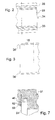
- FIG. 12 shows a foot part 9 with a latent storage 3 lying therein , which is arranged at the lower edge of a container which can be temperature-controlled and a transport container 1 which closes it tightly.
- the foot part 9 also has a cylindrical insulating body 2 . This is in the foot part 9, which consists of a hard plastic shell, foam-molded with plastic and sealed at the edge.
- the structure of the insulating body 2 with the support structures 4 arranged in the interior is basically the same as the cover 12 described in Example 7. This also ensures high-vacuum superinsulation for the base part 9 .
- FIG. 13 shows a partial section through two interchangeable temperature-controllable containers 1 with the respective ends of inner tube 15 and outer tube 33 .
- the containers 1 which are indicated and placed one above the other - as they were characterized in more detail in Example 5 - are firmly connected to one another by a connecting element 55 .
- the connecting element 55 consists of a hard plastic shell, in which an insulating body 10 is foamed in a dimensionally stable manner with plastic.
- the insulating body 10 consists of a cylindrical inner tube 19 and a cylindrical outer tube 18, which are vacuum-tightly connected at their respective end faces to the weld seam 44 .
- circumferential formations or neckings which are designed with at least two degrees of freedom as spring or expansion elements, are arranged on the inner tube 19 and / or the outer tube 18 .
- the formations or neckings are only molded onto the inner tube 19 .
- Support structures 4 according to Example 7 are arranged in the interior of the insulating body 10 .
- the support structures 4 serve to transmit or compensate forces between the inner tube 19 and the outer tube 18 , which occur as a result of the evacuation of the inner atmosphere of the insulating body 10 .
- the insulating body 10 is all-round, that is to say double-cylindrical, and fills the largest possible space within the dimensionally stable foam insulation of the connecting element 55 . To avoid or minimize thermal bridges, the insulating body 10 extends at a defined distance over the front ends of the inner tube 15 and Outer tube 33 of the container 1 also.
- annular edge or insulating ring 11 in which the cover 12 is inserted, is constructed.
- the annular rim or insulation ring 11 receives the lid 12 for closing the container 1 .
- the arrangement of the insulating body 10 takes place within the annular rim 11, as described in Example 9, namely as close to the edge 12 to the cover 12 and to the container 1 as possible in terms of production technology in order to minimize or completely exclude thermal bridges.
- the annular edge 11 consists of a hard, preferably two-part plastic shell, into which the insulating body 10 is inserted and the remaining interior of the plastic shell of the annular edge 11 is foam-filled with plastic and closed with one or more plastic shells ,
- the cover 12 consists essentially of plastic with an insulating body 14 as a high vacuum super insulator.
- the insulating body 14 is surrounded by one or more layers of metal-vapor-coated plastic film 22 or thin metal film which rests on one or more layers of glass fleece 23 , the glass fleece layers 23 being supported by one or more layers, here in this exemplary embodiment by two layers of support structures 4 , Layers of glass fleece 23 and metal-coated plastic film 22 are in turn arranged between the two layers of support structures 4 .
- the layers of glass fleece 23 and metal-coated plastic film 22 or thin metal film lying between the support structures 4 are perforated in order to enable the interior to be evacuated quickly and almost completely.
- the cover 12 is surrounded by a cover layer 20 , which preferably consists of epoxy resin.
- a cover layer 20 which preferably consists of epoxy resin.
- One or more layers of a metal-vapor-coated plastic film 22 or thin metal film are incorporated in the cover layer 20 .
- the lower part of the cover 12 directed towards the interior of the container 1 is preferably prefabricated and then several layers of laminate layers 21 are applied for the dimensionally stable shaping of the upper overlapping edge region.
- the upper part of the cover 12 is also provided with a cover layer 20 and the handle 32 is mounted.
- the interior of the insulating body 14 is evacuated to form a high-vacuum superisolator in a manner known per se via an evacuation connection piece - not shown in FIG. 14 - expediently via the upper inner cover area.
- the support structures 4 which are arranged one above the other in several layers, consist, as described in the previous examples, of round or polygonal interconnected cell structures. If the support structures 4 are staggered, glass fleece layers 23 and / or metal-coated plastic foils 22 are interposed.
- the overall structure of the lid ensures secure sealing and bonding of the metal-vapor-coated plastic film 22 and thus a high vacuum that lasts for years.
- the layers of glass fleece 23 inserted within the insulating body 14 are selected to have a particular thickness. A correspondingly thicker glass fleece layer 23 is then used as an evacuation drainage.
- a construction of a cover 12 with a high vacuum super insulator is also selected according to the invention for the construction of a foot part 9 , with the cylindrical insulating body 2 shown in Example 8 and FIG. 12 being exchanged in principle for the insulating body 14 .
- the insulating body 14 is not, as described in Example 8, foamed in a dimensionally stable manner with plastic, but instead is formed in several layers of metal-vapor-coated plastic film 22, glass fleece layers 23 and laminate layers 21 , which are each glued and sealed with epoxy resin.
Landscapes
- Engineering & Computer Science (AREA)
- Mechanical Engineering (AREA)
- Physics & Mathematics (AREA)
- Thermal Sciences (AREA)
- General Engineering & Computer Science (AREA)
- Chemical & Material Sciences (AREA)
- Combustion & Propulsion (AREA)
- Food Science & Technology (AREA)
- Packages (AREA)
- Table Devices Or Equipment (AREA)
Abstract
Description
Die Erfindung betrifft ein wechselbar temperierfähiges Behältnis mit Vakuumisolierung, Energiespeichern, einem oder mehreren Lagerräumen, verschiedenen hochisolierenden Komponenten und einem Temperaturmess-, -speicher- und Datenübertragungssystem.The invention relates to an interchangeable container with vacuum insulation, Energy storage, one or more storage rooms, various highly insulating components and a temperature measurement, storage and data transmission system.
Es sind verschiedene, meist doppelwandige Behältnisse bekannt für die Lagerung unterschiedlicher
Medien bzw. Materialien, für die Speicherung tiefsiedender verflüssigter Gase, aber auch
als kombinierte Transport- und Lagerbehälter zum zeitweisen Speichern eines vorbestimmten
Temperaturbereichs zur Heiß- bzw. Warmhaltung oder Kalt- bzw. Kühlhaltung. Diese Behälter
weisen sehr unterschiedliche isolierende Komponenten wie zum Beispiel Polyurethan, Styropor,
Korkplatten, evakuierte Zwischenräume und/oder Vakuumisolationspaneele als Ummantelung
auf.
So sind Behälter bekannt für den Frischfisch-Transport, für Nahrungsmittel, lebende Organe,
Mikroorganismen und andere Materialien, die in einem bestimmten Temperaturbereich gelagert
und/oder transportiert werden müssen. Bei der Lagerung derartiger Materialien gibt es im allgemeinen
keine Probleme, diese in einem bestimmten Temperaturbereich aufzubewahren, da bei
stationären Behältnissen ein Ausgleich auftretender Temperaturdifferenzen vor Ort leicht möglich
ist. Anders sieht es mit Transportbehältnissen aus. So kann beispielsweise bei einem Transport
von biologischem Material über weite Entfernungen - z.B. einem interkontinentalen Flug-die
Einhaltung eines konstanten Temperaturbereichs regelmäßig nicht gewährleistet werden.
Unerwünschte Temperaturänderungen sind die Folge, und transportiertes Material ist oftmals
verdorben.
In der EP 209 003 A2 wird ein doppelwandiger isolierter Behälter für die Speicherung tiefsiedender
verflüssigter Gase beschrieben. Der Behälter weist einen Innen- und einen Außenbehälter
auf, wobei der Innenbehälter durch ein sogenanntes Halsrohr mit der Öffnung des Außenbehälters
verbunden ist. Der zwischen Innen- und Außenbehälter vorhandene Raum ist ausgefüllt mit
einer Isolierung, die zumeist aus Schaumstoff besteht. Various, mostly double-walled containers are known for storing different media or materials, for storing low-boiling liquefied gases, but also as combined transport and storage containers for temporarily storing a predetermined temperature range for keeping hot or warm or keeping cold or cold , These containers have very different insulating components such as polyurethane, styrofoam, cork sheets, evacuated spaces and / or vacuum insulation panels as a casing.
Containers are known for the transport of fresh fish, for food, living organs, microorganisms and other materials that have to be stored and / or transported in a certain temperature range. When storing such materials, there are generally no problems in storing them in a certain temperature range, since in the case of stationary containers it is easily possible to compensate for temperature differences that occur on site. The situation is different with transport containers. For example, when transporting biological material over long distances - for example, an intercontinental flight - it cannot be guaranteed that a constant temperature range is maintained. This results in undesirable changes in temperature and the material transported is often spoiled.
EP 209 003 A2 describes a double-walled insulated container for storing low-boiling liquefied gases. The container has an inner and an outer container, the inner container being connected to the opening of the outer container by a so-called neck tube. The space between the inner and outer container is filled with insulation, which is usually made of foam.
Ein ähnlicher Behälter wird in der DE-OS 29 26 646 beschrieben, bei dem der innere Behälter
mit einer Vakuumdämmung umgeben ist, wobei die Vakuumdämmung in einem gesonderten,
das Innenbehältnis umschließenden, aber das Außenbehältnis nicht berührenden Behältnis angeordnet
ist.
Die in den beiden genannten Schriften beschriebenen Behältnisse weisen als Übergang vom Außenbehältnis
zum Innenbehältnis einen spitzwinklig langgezogenen Bereich auf, um möglichst
Wärmebrücken und damit einhergehende Temperaturverluste so gering wie möglich zu halten.
Dadurch nimmt - wie auch aus den Figuren der genannten Schriften ersichtlich - der obere zur
Öffnung hin gestreckte Teil der Isolierung den größten Teil des Innenraums ein. Dementsprechend
klein kann dann nur das für die Lagerung bestimmter Materialien vorgesehene Innenbehältnis
gestaltet werden. Herkömmliche Behältnisse haben demzufolge ein sehr ungünstiges
Verhältnis von innerem Lagerraum zu dem von der Außenhaut umgebenen Raum.
Bekannt ist auch ein dickwandiges hülsenförmiges Behältnis aus der DE 44 38 141 A1 (Spalte 7,
Zeile 52), welches über eine Schraubvorrichtung mit einem weiteren hülsenförmigen Behältnis
übereinander stapelbar zu verschrauben ist. Das Behältnis ist mit einem sogenannten Temperierakku",
welcher in den Deckel und in den Boden als einflanschbares und austauschbares Plattenelement
eingelegt ist, ausgestattet. Der Deckel und der Boden besagten Behältnisses sind in
dieses einzuschrauben. Alternativ wird das Behältnis gemäß dieser Erfindung im oberen Bereich
von einer rundum auf dem Gefäßbehälterrand aufgedrückten Deckelverschließvorrichtung, in
welche ein Deckel mit Temperierakku einlegbar ist, umgeben. Die Deckelverschließvorrichtung
dient dazu, einen Temperierakku auszutauschen, ohne dabei das Behältnis zu öffnen. So wird
beim Tausch von Akkus die Innentemperatur des Behältnisses nicht beeinträchtigt. Das Behältnis
gemäß dieser Erfindung dient sowohl der Kühlhaltung als auch der Heiß- bzw. Warmhaltung
von im Inneren des Behältnisses befindlichen Stoffen.
Ebenfalls einen Kühlakku in einem Deckel und/oder in einem Gehäuseunterteil weist ein Behälter
für Lebensmittel nach EP 0 153 975 A1 auf, wobei der Kühlakku oder ein Kühlmedium
wahlweise austauschbar oder fest eingeschweißt sind.
Aus der EP 178 337 A1 ist ein Container für die Lagerung von tiefgefrorenem Material bekannt.
Der Container besteht aus einem äußeren und einem inneren Gefäß, wobei letzteres über eine
Bodenöffnung in das äußere Gefäß einbringbar ist und das äußere Gefäß und das innere Gefäß
mit je einem Fußteil hermetisch verschlossen werden. Im Zwischenraum zwischen äußerem und
innerem Gefäß wird in konventioneller Weise Vakuum als Isolierung erzeugt.
Aus der EP 1 006 058 A1 ist ein Behälter mit kompakter Wandung aus wärmeisolierendem Material
bekannt, bei dem die Oberfläche der verschließenden Randbereiche zwischen Deckel und
Behälterkörper zur Verhinderung des Ausströmens von Wärme mit einer Dichtmasse versehen
wird.
Ein weites Spektrum innerhalb des Standes der Technik nehmen flaschenförmige kleinere Behältnisse
mit Vakuumisolierung ein. Das Innenbehältnis ist im Außenbehältnis freihängend am
oberen Rand des Außenbehältnisses befestigt. (GB 2 129 117 A, DE 31 45 916 A1,
EP 0 147 165 A2 und EP 0 880 929 A2). Ebenfalls freihängend sind die inneren flaschenförmigen
Behältnisse am oberen Rand des Außenbehältnisses befestigt, aber mit einer Unterstützung
versehen, wie beispielsweise in der EP-0 109 262 A1 beschrieben.
Derartige flaschenförmige Behältnisse sind nur sehr bedingt und dann auch nur für die Aufbewahrung
kleinster Mengen einsetzbar. Durch die freihängende Befestigung des Innenbehältnisses
am Rand des Außenbehältnisses ist die Füllung der Lagerräume, selbst bei größerer Dimensionierung
der Behältnisse, mit einem größeren Lagergewicht nicht möglich. Außerdem ist man
immer an eine runde oder fast runde Form gebunden.
Aus der DE 40 29 405 A 1 ist ein im Innenraum evakuierter Formkörper zur Wärmedämmung
bekannt, dessen Umhüllung aus einer gas- und wasserdichten und metallfreien Folie besteht.
Durch den Verzicht auf metallische Bestandteile in der Folie vermeidet man unerwünschte
Wärmebrücken, insbesondere in den Randbereichen des wärmedämmenden Formkörpers. Die in
dieser Schrift geforderte Gas- und Wasserdampfdichtigkeit der Folien ist jedoch nur gewährleistet,
wenn die Kunststofffolien einen speziellen Schichtaufbau aufweisen. Diese Folien sind jedoch
aufwendig herzustellen und damit relativ teuer. Die Dicke der Folien liegt im Bereich von
bis zu 1 mm. Zum Teil muss das Material vor dem Einsatz als Umhüllung für Vakuumisolationspaneele
durch ein Tiefziehverfahren in die entsprechende Form gebracht werden. Derartige
Vakuumisolationspaneele dienen vielfach auch der Isolation von wechselbar temperierfähigen
Behältnissen.
Vakuumisolationspaneele mit Umhüllungen aus Metall oder metallhaltigen, zumeist aluminiumhaltigen
oder metallkaschierten Folien sind ebenfalls bekannt. Gebräuchliche Aluminiumverbundfolien
besitzen aufgrund der Metallschicht eine für die erforderliche Lebensdauer ausreichende
Diffusionsdichtigkeit für Wasser und Luft. Bei diesen Vakuumisolationspaneelen sind
die kritischen Zonen die Randbereiche, weil dort die aneinanderstoßenden Metallschichten am
Rand der Vakuumisolationspaneele Wärmebrücken verursachen. In die Vakuumisolationspaneele
wird poröses Isolationsmaterial zwischen die Edelstahlbleche eingelegt. Boden- und Deckbleche
werden in geeigneter Weise am Rand miteinander verschweißt (DE 42 14 002 A1). Eine
externe Evakuierung erfolgt über eine Öffnung bzw. ein Evakuierungsröhrchen, das sich im
Randverbund oder in der Mitte einer der Abdeckbleche befindet.
Aus der DE 197 25 818 A 1 ist eine Wärmedämmung mit Matten aus Folienmaterial und Vakuum
bekannt. Der Schichtaufbau wird in dieser Schrift als Mehrschichtisolierung beschrieben,
wobei wechselnde Schichten aus Aluminiumfolie und Glasfasergewebe eine Matte bilden. Diese
Matten sind mit schlecht wärmeleitenden Fixierelementen auf einem Unterbau aus Kupferblech
befestigt. Es wird beschrieben, dass abwechselnd aus Wärmestrahlen, reflektierendem Material
und schlecht wärmeleitendem Material bestehende Schichten in den Matten getrennte Lagen
bilden. Als schlecht wärmeleitende Materialen werden in dieser Schrift Beschichtungen aus Folie,
Faserschicht, Gewebe, insbesondere Glasfasergewebe, erwähnt.
Bei Vakuumisolationen ist es üblich, pulverförmige oder körnige, druckfeste Isoliermaterialen
als Füllstoff zu verwenden. Einerseits um die Wärmeverluste durch Strahlung und Konfektion zu
reduzieren, andererseits um die Wände gegen den Umgebungsdruck auf Distanz zu halten bzw.
um Kräfte von einer Wand auf die gegenüberliegende Wand zu übertragen.
Die besonderen Probleme bei den bekannten Ausführungsformen konzentrieren sich auf die Einfüll-
und Entnahme- bzw. Öffnungsbereiche sowie die Bodenbereiche bei der Reduzierung oder
Vermeidung von Wärmebrücken. Ebenso problematisch sind die Übergangsbereiche an den
Verbindungen von Innen- und Außenwand bzw. Innen- und Außenbehälter.
Alle beschriebenen Behälter sind trotz teilweiser Verwendung von guten Isolationsmaterialien
wie Polyurethan, Styropor, Korkplatten und dergleichen aber auch Vakuum nicht geeignet, Stoffe,
die beispielsweise für die Aufbewahrung von menschlicher Haut bei Temperaturen in einem
Bereich von etwa -80 °C zu lagern sind, über einen Zeitraum > 36 - 40 Stunden aufzubewahren.
Darüber hinaus sind alle Behältnisse relativ schwer und dickwandig und damit materialintensiv
hergestellt. In der Praxis angebotene Transportbehälter mit Vakuumisolierung weisen z.B. 2 mm
starke Innen- und Außenwände auf und erreichen Standzeiten von nur 36 Stunden bei einer gewünschten
Lagertemperatur im Bereich um -80 °C.
Weitere Nachteile ergeben sich durch die dickeren Wandungen in einem stärkeren Schweißverzug,
in Eigenspannungen und Oberflächendellen. Die größeren Materialstärken wirken negativ
auf das Behältergewicht, sind besonders nachteilig bei Lufttransporten und haben wegen des
höheren Wärmeflusses negative Auswirkungen auf die Standzeiten. Im Verhältnis zum Lagervolumen
haben alle bekannten Behältnisse kleine Einfüll- bzw. Entnahmeöffnungen. A similar container is described in DE-OS 29 26 646, in which the inner container is surrounded by vacuum insulation, the vacuum insulation being arranged in a separate container enclosing the inner container but not touching the outer container.
The containers described in the two cited documents have an elongated area at an acute angle as a transition from the outer container to the inner container, in order to keep thermal bridges and the associated temperature losses as low as possible. As a result, as can also be seen from the figures of the cited documents, the upper part of the insulation which extends towards the opening takes up the largest part of the interior. Accordingly, only the inner container provided for the storage of certain materials can be made small. Conventional containers therefore have a very unfavorable ratio of the inner storage space to the space surrounded by the outer skin.
A thick-walled sleeve-shaped container is also known from
Also a cooling battery in a lid and / or in a lower housing part has a container for food according to EP 0 153 975 A1, the cooling battery or a cooling medium being either exchangeable or permanently welded.
A container for the storage of deep-frozen material is known from EP 178 337 A1. The container consists of an outer and an inner vessel, the latter being insertable into the outer vessel via a bottom opening and the outer vessel and the inner vessel each being hermetically sealed with a foot part. In the space between the outer and inner vessel, vacuum is generated as insulation in a conventional manner.
A wide range within the state of the art are bottle-shaped smaller containers with vacuum insulation. The inner container is freely suspended in the outer container at the upper edge of the outer container. (
Such bottle-shaped containers are only very limited and can then only be used for the storage of very small quantities. Due to the free-hanging fastening of the inner container at the edge of the outer container, it is not possible to fill the storage rooms with a larger storage weight, even with larger dimensions of the containers. In addition, you are always bound to a round or almost round shape.
From DE 40 29 405
Containers.
Vacuum insulation panels with envelopes made of metal or metal-containing, mostly aluminum-containing or metal-clad films are also known. Due to the metal layer, common aluminum composite foils have sufficient diffusion tightness for water and air for the required service life. With these vacuum insulation panels, the critical zones are the edge areas, because there the abutting metal layers on the edge of the vacuum insulation panels cause thermal bridges. Porous insulation material is placed between the stainless steel sheets in the vacuum insulation panels. Bottom and cover plates are welded together in a suitable manner at the edge (
From DE 197 25 818 A 1 thermal insulation with mats made of film material and vacuum is known. The layer structure is described in this document as multi-layer insulation, with alternating layers of aluminum foil and glass fiber fabric forming a mat. These mats are attached to a base made of copper sheet with poorly heat-conducting fixing elements. It is described that layers consisting of heat rays, reflective material and poorly heat-conducting material alternately form separate layers in the mats. In this document, coatings made of film, fiber layer, fabric, in particular glass fiber fabric, are mentioned as poorly heat-conducting materials.
In vacuum insulation, it is common to use powdery or granular, pressure-resistant insulating materials as fillers. On the one hand to reduce the heat loss through radiation and assembly, on the other hand to keep the walls at a distance against the ambient pressure or to transfer forces from one wall to the opposite wall.
The particular problems with the known embodiments concentrate on the filling and removal or opening areas and the bottom areas in the reduction or avoidance of thermal bridges. The transition areas at the connections between the inner and outer wall or inner and outer container are equally problematic.
Despite the partial use of good insulation materials such as polyurethane, styrofoam, cork sheets and the like, but also vacuum, all of the containers described are not suitable for storing substances that are to be stored, for example, for the storage of human skin at temperatures in a range of approximately -80 ° C. keep for a period> 36 - 40 hours.
In addition, all containers are relatively heavy and thick-walled and therefore made of material-intensive. Transport containers with vacuum insulation offered in practice have, for example, 2 mm thick inner and outer walls and achieve a service life of only 36 hours at a desired storage temperature in the range of -80 ° C.
Further disadvantages result from the thicker walls in a stronger welding distortion, in residual stresses and surface dents. The larger material thicknesses have a negative effect on the container weight, are particularly disadvantageous for air transport and have a negative impact on the service life due to the higher heat flow. In relation to the storage volume, all known containers have small filling or removal openings.
Die Aufgabe der Erfindung besteht darin, die Nachteile der bekannten Behälter und isolierenden Komponenten zu beseitigen oder zumindest so zu minimieren, dass Standzeiten für Behälter, beispielsweise für den Transport und die Aufbewahrung von tiefkalten biologischen Proben, Organen, Kulturen und dergleichen in einem Temperaturbereich von -90 °C bis -75 °C von > 50 Stunden, vorzugsweise > 100 Stunden, erzielbar sind. Mit der erfindungsgemäß vorzuschlagenden Lösung soll das Nachladen von Energiespeichern erst nach > 100 Stunden erforderlich werden. Ferner ist es Aufgabe der Erfindung, die Behälter leichter zu gestalten, ihre Herstellung zu vereinfachen und ein günstiges Verhältnis zwischen innerem Lagerraum und dem von der Au-βenhaut umgebenen Raum herzustellen, um somit Material und Kosten zu sparen. Die Verwendung von flüssigem Stickstoff soll generell ausgeschlossen werden.The object of the invention is to overcome the disadvantages of the known and insulating containers Eliminate components or at least minimize them so that downtimes for containers, for example for the transport and storage of cryogenic biological samples, Organs, cultures and the like in a temperature range from -90 ° C to -75 ° C of> 50 Hours, preferably> 100 hours, can be achieved. With the one to be proposed according to the invention Solution, the recharging of energy storage should only become necessary after> 100 hours. Furthermore, it is an object of the invention to make the containers lighter, their manufacture simplify and a favorable relationship between the inner storage space and that of the outer skin to create the surrounding space in order to save material and costs. The usage Liquid nitrogen should generally be excluded.
Erfindungsgemäß wird diese Aufgabe dadurch gelöst, dass mit einer neuartigen vorteilhaften
Kombination von unterschiedlichen Isolationskomponenten ein wechselbar temperierfähiges
Behältnis mit hocheffektiven Isolationseigenschaften vorgeschlagen wird, bei welchem die kritischen
Zonen, insbesondere Übergangsbereiche von Innen- und Außenwandungen, Öffnungsbereiche
und Übergangsbereiche unterschiedlicher Werkstoffe vor einfallender Wärme erfindungsgemäß
geschützt und isoliert werden und einbringbare und nachladbare Latentenergie-,
sensorische Energie- und/oder chemische Energiespeicher Standzeiten erfindungsgemäßen Behälters
über einen Zeitraum von ≥ 140 Stunden gewährleisten.
Die erfindungsgemäße Kombination einzelner Isolationskomponenten beruht auf der aufeinander
abgestimmten Verwendung von
- Hochvakuum-Superisolation in Ummantelungen mit Abstandhalter und metallbedampfter Reflexionsfolie mit einer Wärmeleitzahl von cirka 0,1 mW/mK,
- formstabiler Schaumstoff-Isolation mit Randverstärkung und einer Wärmeleitzahl von cirka 10 mW/mK,
- Hochvakuum-Superisolation in Hohlkörpern mit Stützstruktur mit einer Wärmeleitzahl von cirka 0,1 mW/mK,
- Reflexionsmaterialien zwischen Innen- und Außenwand der Hochvakuum-Superisolation,
- Vakuum- und Hochvakuum-Isolierkomponenten aus Kunststoff, Glas, Keramik und/oder Metall mit in der Evakuierungszone angeordneten Stützstrukturen und mit Abstandhalter und metallbedampfter Reflexionsfolie zum Einbringen in formstabile Schaumstoffisolationen,
- der Anwendung an sich bekannter Getterung des evakuierten Innenraums mit Abgabe des Gettermaterials aus Vorrichtungen,
- der Anwendung materialschwacher bombierter Behälterwandungen sowie
- materialschwacher und langgestreckter, in mindestens zwei Freiheitsgraden bewegbarer Übergängen von einer äußeren zu einer inneren Ummantelung zur Verminderung bzw. Verlängerung des Wärmeflusses und Senkung des Behältergewichts und
- der alternativen Verwendung von Folien-Vakuumisolationen (Vakuum-Isolier-Paneele) als hocheffektive Wärmeschilde mit einer Wärmeleitzahl von cirka 4 mW/mK.
The combination of individual insulation components according to the invention is based on the coordinated use of
- High vacuum super insulation in jackets with spacers and metal-coated reflective tape with a thermal conductivity of around 0.1 mW / mK,
- dimensionally stable foam insulation with edge reinforcement and a thermal conductivity of around 10 mW / mK,
- High vacuum super insulation in hollow bodies with a support structure with a thermal conductivity of around 0.1 mW / mK,
- Reflective materials between the inner and outer wall of the high vacuum super insulation,
- Vacuum and high vacuum insulation components made of plastic, glass, ceramic and / or metal with support structures arranged in the evacuation zone and with spacers and metal-coated reflective tape for insertion into dimensionally stable foam insulation,
- the use of known gettering of the evacuated interior with delivery of the getter material from devices,
- the use of weakly arched container walls and
- Material-weak and elongated transitions, which can be moved in at least two degrees of freedom, from an outer to an inner casing for reducing or lengthening the heat flow and reducing the container weight and
- the alternative use of foil vacuum insulation (vacuum insulation panels) as highly effective heat shields with a thermal conductivity of around 4 mW / mK.
Die alternativ einzusetzende Folien-Vakuumisolation als hocheffektiver Wärmeschild ist zumeist
pulver- oder füllstoffgestützt und von scheiben-, platten-, ring-, topf-, zylinder-, hohlzylinderoder
kreissegmentförmiger Gestalt und ist vorzugsweise in Wandungselementen und Konstruktionen
fest eingeschäumt angeordnet, wobei die Folien-Vakuumisolation in Bereichen potentieller
Wärmebrücken hinter- bzw. übereinander versetzt angeordnet ist.
Die Hochvakuum-Superisolation besteht aus einem doppelwandigen System mit aus etwa parallel
zueinander verlaufendem Außenmantel und Innenmantel gebildetem geschlossenen Hohlkörper
mit bis zum Hochvakuumbereich evakuierter Innenatmosphäre.
Der Innenmantel ist zur Vermeidung von Wärmeverlusten an seinen beiden Enden umlaufend
dünner ausgebildet und weist langgezogene und ein- oder mehrfach gebogene Enden auf, die mit
dem Außenmantel vakuumdicht verschweißt sind. Diese Enden weisen mindestens zwei Freiheitsgrade
auf und fungieren somit als Feder- bzw. Dehnungselement. Gemäß der Erfindung
haben die Enden des Innen- und/oder des Außenmantels jede beliebige den Wärmeweg verlängernde
Form. In den Innen- und/oder Außenmantel eingeformte Sicken führen zur Stabilisierung
gegen Implosion und damit zur Verminderung der Wandstärken und gewährleisten einen weiteren
elastischen Ausgleich zwischen Innen- und Außenmantel.
Die formstabile Schaumstoff-Isolation ist in schalenförmige Umhüllungen eingebracht, die beispielsweise
aus Edelstahlblech oder Kunststoff geformt sind, und dient der Arretierung und dem
Schutz von eingelegten Isolierkomponenten verschiedenster Form, fernerhin der mechanischen
Stabilität umhüllender, verbindender oder verschließender Konstruktionen sowie der Vermeidung
bzw. Verringerung von Wärmebrücken.
Die Hochvakuum-Superisolation in Hohlkörpern mit Stützstrukturen in umhüllenden, verbindenden
oder verschließenden Konstruktionen besteht aus einer Ummantelung mit Innenraum, in
dem Stützstrukturen angeordnet sind. Die Stützstrukturen füllen den Innenraum des Hohlkörpers
partiell oder fast vollständig in einer oder mehreren Lagen nebeneinander und/oder übereinander
aus. Die Stützstrukturen bestehen einerseits aus kreis- oder polygonförmigen Zellen, die versetzt
übereinander und/oder nebeneinander in mehreren Lagen so angeordnet sind, dass die jeweils
übereinander angeordneten Zellenwände sich nur punktförmig berühren. Die Stützstruktur aus
kreis- oder polygonförmigen Zellen ist ein vertikal zellenförmig angeordnetes Material, das beispielsweise
aus beschichteten Papier-, Glas-, Keramik- oder Kunststoffstrukturen besteht.
Andererseits sind die Stützstrukturen von zu Ringen geformter, etwa schlauchförmiger Gestalt
(Torus) oder als Vollring ausgebildet und sind im Innenraum des Hohlkörpers ringförmig, vorzugsweise
in mehreren Ringen nebeneinander angeordnet. Die schlauchförmigen oder als Vollring
ausgebildeten Stützstrukturen bestehen aus glasfaserverstärktem Kunststoff.The alternatively used foil vacuum insulation as a highly effective heat shield is mostly powder or filler-based and of disc, plate, ring, pot, cylinder, hollow cylinder or circular segment shape and is preferably arranged in foam in wall elements and constructions, with the foil Vacuum insulation in areas of potential thermal bridges is arranged one behind the other or one above the other.
The high-vacuum super insulation consists of a double-wall system with a closed hollow body formed from an approximately parallel outer jacket and an inner jacket with an internal atmosphere evacuated up to the high vacuum area.
In order to avoid heat losses, the inner jacket is designed to be thinner all around at both ends and has elongated and single or multiple bent ends which are welded to the outer jacket in a vacuum-tight manner. These ends have at least two degrees of freedom and thus act as a spring or expansion element. According to the invention, the ends of the inner and / or outer jacket have any shape that extends the thermal path. Beadings molded into the inner and / or outer jacket lead to stabilization against implosion and thus to a reduction in wall thicknesses and ensure a further elastic compensation between the inner and outer jacket.
The dimensionally stable foam insulation is placed in shell-shaped coverings, which are made of stainless steel sheet or plastic, for example, and is used to lock and protect inserted insulating components of various shapes, as well as the mechanical stability of enclosing, connecting or sealing constructions, and to avoid or reduce them thermal bridges.
The high vacuum super insulation in hollow bodies with support structures in enveloping, connecting or sealing constructions consists of a casing with an interior in which support structures are arranged. The support structures partially or almost completely fill the interior of the hollow body in one or more layers next to one another and / or one above the other. The support structures consist, on the one hand, of circular or polygonal cells, which are staggered one above the other and / or next to one another in several layers such that the cell walls arranged one above the other only touch one another in a punctiform manner. The support structure made of circular or polygonal cells is a vertically cell-shaped material, which consists for example of coated paper, glass, ceramic or plastic structures.
On the other hand, the support structures are designed in the form of rings, for example in the form of a tube (torus) or as a full ring and are arranged in a ring shape in the interior of the hollow body, preferably in a plurality of rings next to one another. The tubular or full-ring support structures are made of glass fiber reinforced plastic.
Gemäß der Erfindung werden isolierende Komponenten vorgeschlagen, die Evakuierungszonen mit in diesen angeordneten Stützstrukturen aufweisen. Diese isolierenden Komponenten sind für die besonders kritische Bereiche von wechselbar temperierfähigen Behältnissen, wie z.B. Deckel, Isolations- bzw. ringförmiger Rand, Fußteil und Verbindungselemente für die Stapelung mehrerer Behälter übereinander, vorgesehen. Sie werden in den Wänden von Deckel, Fußteil und Verbindungselement sowie des Isolationsrings angeordnet. Die Wände bestehen vorzugsweise aus Kunststoff.According to the invention, insulating components are proposed, the evacuation zones with support structures arranged in them. These insulating components are for the particularly critical areas of interchangeable containers, e.g. Cover, Insulation or ring-shaped edge, foot part and connecting elements for stacking several containers one above the other. They are in the walls of the lid, base and Connection element and the insulation ring arranged. The walls are preferably made made of plastic.
Gemäß der Erfindung wird vorgeschlagen, ein wechselbar temperierfähiges Behältnis mit aus
etwa parallel zueinander verlaufendem Außenmantel und Innenmantel gebildetem geschlossenen
Hohlkörper als Ummantelung mit bis zum Hochvakuumbereich evakuierter Innenatmosphäre,
einem eine Öffnung des Hohlkörpers verschließenden Fußteil und einem eine weitere Öffnung
des Hohlkörpers verschließenden Deckel, oder diese weitere Öffnung des Hohlkörpers durch
einen Randbereich mit innenliegendem Deckel verschließbar ist und das wechselbar temperierfähige
Behältnis einen oder mehrere Energiespeicher sowie einen Lagerraum aufweist.
Der erwähnte Hohlkörper ist vorzugsweise von rohrförmiger Gestalt und bildet einen Hohlzylinder,
dessen Außenmantel ein Außenrohr und dessen Innenmantel ein Innenrohr ist. Das Außenrohr
und das Innenrohr sind an den jeweiligen Stirnseiten miteinander hermetisch verbunden. Im
Bereich dieser hermetischen Verbindung sind an dem Innenrohr und/oder dem Außenrohr umlaufende
Ausformungen oder Aushalsungen, welche mit mindestens zwei Freiheitsgraden als
Feder- bzw. Dehnungselemente ausgebildet sind. Über die Ausformungen oder Aushalsungen
erfolgt ein Ausgleich der Materialverformung, die in Folge der Differenzen der am Innenrohr
und am Außenrohr anliegenden Temperaturen auftritt. Die Ausformungen oder Aushalsungen
von Innenrohr und/oder Außenrohr bilden eine gedachte umlaufende Ringkammer, die die Form
eines Körpers hat, der sich bei der Bewegung einer ebenen Figur längs einer geschlossenen Kurve
- beispielsweise durch deren Drehung um die Achse, welche in der Ebene dieser Figur liegt
und sich nicht schneidet - ergibt. Die umlaufenden Ausformungen oder Aushalsungen an den
Stirnseiten des Innenrohrs und des Außenrohrs haben gemäß der Erfindung unterschiedliche
Formen, vorzugsweise sind sie doppelsinusförmig bzw. S-förmig oder kreisbogenförmig ausgebildet.
In jedem Fall verlängern die Ausformungen oder Aushalsungen den Wärmeweg zwischen
dem Innenrohr und dem Außenrohr. Die Wärmeübertragung wird über die Ausformungen oder
Aushalsungen auch dadurch vermindert, dass die Materialstärken dieser um mindestens ein Viertel
geringer sind als die Materialstärken von Innen- und Außenrohr.
Gemäß der Erfindung werden das die eine Öffnung des Hohlkörpers verschließende Fußteil und
der die andere Öffnung des Hohlkörpers verschließende Randbereich von, an den jeweiligen
Stirnseiten des Hohlkörpers umlaufenden, nach innen und/oder außen gerichteten Stabilisierungselementen
und/oder aufschäumenden Klebern gehalten. Die Stabilisierungselemente sind
vorteilhafterweise als Sicken ausgebildet.
Zur weiteren Verbesserung der Wärmeisolation ist das Innenrohr mit einer Superisolationswicklung,
bestehend aus Abstandhalter, strahlungsreflektierenden Materialien und wahlweiser Einbringung
eines chemischen Getters oder eines Adsorptionsmaterials ausgestattet.
Das wechselbar temperierfähige Behältnis ist - wie bereits ausgeführt - im oberen Bereich mit
einem verschließenden Rand mit innenliegendem Deckel und im unteren Bereich mit einem Fußteil
versehen. Diese den Hohlkörper an seinen Stirnseiten verschließenden Teile bestehen aus
hochisolierenden Schaumstoffen, die mit einer Schale ummantelt sind. Innerhalb des verschließenden
Randes, dem Deckel und dem Fußteil sind innerhalb der jeweiligen Schalen mit hochisolierendem
Schaumstoff weitere hochisolierende Komponenten angeordnet.According to the invention, it is proposed to use an interchangeable temperature-controlled container with a closed hollow body formed from approximately parallel mutually extending outer jacket and inner jacket as a jacket with an inner atmosphere evacuated up to the high vacuum region, a foot part closing an opening of the hollow body and a cover closing another opening of the hollow body, or these further opening of the hollow body can be closed by an edge area with an internal cover and the changeable temperature-controlled container has one or more energy stores and a storage room.
The hollow body mentioned is preferably of tubular shape and forms a hollow cylinder, the outer shell of which is an outer tube and the inner shell of which is an inner tube. The outer tube and the inner tube are hermetically connected to one another at the respective end faces. In the area of this hermetic connection, circumferential formations or neckings are formed on the inner tube and / or the outer tube, which are designed with at least two degrees of freedom as spring or expansion elements. The deformations or neckings compensate for the material deformation that occurs as a result of the differences in the temperatures prevailing on the inner tube and on the outer tube. The formations or necklines of the inner tube and / or outer tube form an imaginary circumferential annular chamber, which has the shape of a body which, when a flat figure moves along a closed curve - for example by its rotation about the axis which is in the plane of this figure lies and does not cut - results. According to the invention, the circumferential formations or neckings on the end faces of the inner tube and the outer tube have different shapes, preferably they are double-sinusoidal or S-shaped or circular-arc-shaped. In any case, the formations or neckings extend the heat path between the inner tube and the outer tube. The heat transfer is also reduced via the formations or neckings in that the material thicknesses of these are at least a quarter less than the material thicknesses of the inner and outer tubes.
According to the invention, the foot part which closes an opening of the hollow body and the edge region which closes the other opening of the hollow body is held by stabilizing elements and / or foaming adhesives which run around the respective end faces of the hollow body and are directed inwards and / or outwards. The stabilizing elements are advantageously designed as beads.
To further improve the thermal insulation, the inner tube is equipped with a super insulation winding, consisting of spacers, radiation-reflecting materials and the optional introduction of a chemical getter or an adsorption material.
The changeable temperature-controlled container is - as already stated - provided in the upper area with a closing edge with an internal lid and in the lower area with a foot part. These parts closing the hollow body on its end faces consist of highly insulating foams which are encased in a shell. Further highly insulating components are arranged within the respective shells with highly insulating foam within the closing edge, the lid and the foot part.
Eine andere Ausführungsform des wechselbar temperierfähigen Behälters sieht vor, an der unteren
stirnseitigen Öffnung des Hohlkörpers einen doppelten Boden, wie nachfolgend beschrieben,
anzuordnen. Der doppelte Boden besteht aus definiert vorgeformten bombierten Bodenblechen,
wobei ein Bodenblech den Innenmantel und ein Bodenblech den Außenmantel verschließt, so
dass der Zwischenraum zwischen den beiden Bodenblechen mit dem Zwischenraum zwischen
Innenmantel und Außenmantel des Hohlkörpers in Verbindung steht und in einem Arbeitsgang
evakuiert werden kann. Die Bodenbleche sind randseitig etwa rechtwinklig bogenförmig umgebördelt,
zu ihrem Zentrum hin mit einer definierten Wölbung versehen und bestehen vorzugsweise
aus Stahlblech und sind nach Verschweißen mit dem Außenmantel bzw. mit dem Innenmantel
mit mindestens zwei Freiheitsgraden als Feder- bzw. Dehnungselement ausgebildet. Als
zusätzliche Feder- bzw. Dehnungselemente sind in den Blechböden rundumlaufende Sicken eingeformt.
Die Verbindung von Innenmantel mit dem einen Bodenblech und die andere Verbindung
des äußeren Blechs mit dem Außenmantel erfolgt vakuumdicht. Die Bleche haben eine
Materialstärke, die um mindestens ein Viertel geringer ist als die Materialstärke von Außen- und
Innenmantel.
Zwischen den beiden Blechen sind stützende und beabstandende Stützstrukturen angeordnet. Die
beiden Bleche wölben sich beim Evakuieren definiert zueinander und werden - wie oben beschrieben
- durch Stützstrukturen beabstandet. Am äußeren Bodenblech sind eine konventionelle
Evakuierungsöffnung und ein Behälter für die Aufbewahrung und Abgabe von Gettermaterial
vorgesehen.
Der Bodenbereich des erfindungsgemäßen Behälters ist mit einem Fußteil, bestehend aus einer
Kunststoffschale mit im Inneren angeordnetem formstabilen Schaumkunststoff, ummantelt. Das
Fußteil dient im Wesentlichen dem Schutz des äußeren Behälterbodens und der Verbindungsstellen
zwischen Außenmantel und entsprechendem äußeren Boden.Another embodiment of the changeable temperature-controlled container provides for a double bottom, as described below, to be arranged at the lower end opening of the hollow body. The double bottom consists of preformed cambered bottom plates, a bottom plate closing the inner jacket and a bottom plate closing the outer jacket, so that the space between the two bottom plates is connected to the space between the inner jacket and the outer jacket of the hollow body and can be evacuated in one operation. The bottom plates are flanged at a right angle in an arc shape, are provided with a defined curvature towards their center and are preferably made of sheet steel and, after welding to the outer jacket or to the inner jacket, are designed with at least two degrees of freedom as a spring or expansion element. All-round beads are molded into the sheet metal bottoms as additional spring or expansion elements. The connection of the inner jacket with the one floor panel and the other connection of the outer panel with the outer jacket is vacuum-tight. The sheets have a material thickness that is at least a quarter less than the material thickness of the outside and
Inner sheath.
Supporting and spacing support structures are arranged between the two sheets. During evacuation, the two metal sheets bulge towards each other and are - as described above - spaced apart by support structures. A conventional evacuation opening and a container for storing and dispensing getter material are provided on the outer floor panel.
The bottom region of the container according to the invention is encased with a foot part, consisting of a plastic shell with dimensionally stable foam plastic arranged on the inside. The foot part essentially serves to protect the outer container bottom and the connection points between the outer jacket and the corresponding outer bottom.
Das wechselbar temperierfähige Behältnis wird erfindungsgemäß speziell für den Transport von größeren Einheiten übereinandergestapelt, so dass mehrere Behältnisse einen gemeinsamen Lagerraum bilden, und durch ein oder mehrere Verbindungselemente verbunden sind. Die Verbindungselemente sind ebenso wie Fußteil und verschließender Randbereich an den jeweiligen Stirnseiten des Hohlkörpers an umlaufenden, nach innen und/oder außen gerichteten Stabilisierungselementen arretiert und/oder werden von aufschäumenden Klebern gehalten.According to the invention, the interchangeable temperature-controlled container is specially designed for the transport of Larger units are stacked on top of each other, so that several containers share a common storage space form, and are connected by one or more connecting elements. The fasteners are just like the foot part and closing edge area on the respective End faces of the hollow body on circumferential, inward and / or outward stabilizing elements locked and / or held by foaming glue.
Die vorzuschlagenden isolierenden Komponenten, insbesondere einsetzbar für Deckel, Isolationsring,
Fußteil und Verbindungselement für ein wechselbar temperierfähiges Behältnis, sind
von einer ein- oder mehrteiligen harten Kunststoffschale umgeben, und im Inneren derselben
sind verschiedene Isolierkörper in formstabilem Kunststoffschaum eingebettet. Ein Isolierkörper
ist von flach-zylindrischer Gestalt und findet Verwendung vorzugsweise im Deckel und im Fußteil
eines wechselbar temperierfähigen Behältnisses. Der Isolierkörper besteht aus einem zylindrischen
Mantel, dessen obere und untere Öffnung von vorgeformten bombierten Blechen verschlossen
sind. Vorzugsweise bestehen der zylindrische Mantel und die vorgeformten bombierten
Bleche aus Edelstahlblech, wobei deren Materialstärke um mindestens ein Viertel geringer
dimensioniert ist als die üblichen Wände eines vakuumisolierten wechselbar temperierfähigen
Behälters. Die beiden Bleche und der Mantel sind gemäß der Erfindung in ihren Randbereichen
mit umlaufenden Ausformungen oder Aushalsungen versehen, welche mit mindestens zwei Freiheitsgraden
als Feder- bzw. Dehnungselemente ausgebildet sind. Als zusätzliches Feder- bzw.
Dehnungselement sind die beiden Bleche mit rundumlaufenden Sicken versehen. Unabhängig
von den Ausformungen oder Aushalsungen sind die bombierten Bleche an ihren Rändern umgebördelt
und mit dem Mantel vakuumdicht verschweißt, so dass ein flacher Hohlkörper entsteht.
Dieser Hohlkörper ist in seiner Dimensionierung so gewählt, dass ein Deckel bzw. ein Fußteil in
ihrer größten flächenmäßigen Ausdehnung fast vollständig ausgefüllt sind. Damit werden Wärmebrücken
weitestgehend minimiert bzw. ausgeschlossen. Der Innenraum eines solchen Hohlkörpers
ist partiell oder den Innenraum fast vollständig ausfüllend mit Stützstrukturen versehen
und ist nach Evakuierung des Innenraums ein im Wesentlichen fertiger Isolierkörper. Die Stützstrukturen
haben dabei die Aufgabe, Kräfte von dem einen Blech auf das gegenüberliegende
Blech zu übertragen, und sind in ihrem Aufbau so gewählt, dass sie in mehreren Lagen versetzt
übereinander angeordnet sind. Zwischen mehreren Lagen Stützstrukturen sind in eine oder mehrere
Lagen perforierte Folien und/oder Evakuierungsdrainagen, vorzugsweise Glasvlieslagen,
eingelegt. Die Anordnung der Stützstrukturen kann kreis-, ring-, segment- oder punktförmig
oder den Innenraum eines Hohlkörpers vollständig ausfüllend gewählt werden.
Ein solcher Isolierkörper wird in einem Deckel oder Fußteil eines Behälters bei der Herstellung
so positioniert, dass die Wandung des Isolierkörpers die erwähnte harte Kunststoffschale von
Deckel bzw. Fußteil nicht berührt. Der Isolierkörper wird in erwähnte Kunststoffschalen formstabil
eingeschäumt und damit arretiert. In den Deckel bzw. das Fußteil sind zusätzlich eine oder
mehrere Lagen eines Reflexionsmaterials eingelegt, um eine zusätzliche Strahlungsabschirmung
gegenüber der Außenatmosphäre zu erreichen. Das Reflexionsmaterial kann auch in die erwähnte
harte Kunststoffschale eingearbeitet sein. Nach dem Ausschäumen von Deckel und Fußteil
erfolgt der Verschluss derselben mit weiteren Teilen von passgenauen harten Kunststoffschalen
und Versiegelung der Nahtstellen. Es liegt im Bereich der Erfindung, beispielsweise das Fußteil
passgenau zur Ummantelung des Behälters herzustellen, so dass nur eine Versiegelung zwischen
dem Rand vom Fußteil und der Behälterwand erfolgt.The insulating components to be proposed, in particular usable for cover, insulation ring, foot part and connecting element for an interchangeable temperature-controlled container, are surrounded by a one-part or multi-part hard plastic shell, and various insulating bodies are embedded in dimensionally stable plastic foam inside the same. An insulating body is of flat-cylindrical shape and is preferably used in the lid and in the base part of an interchangeable container. The insulating body consists of a cylindrical jacket, the upper and lower opening of which are closed by preformed convex sheets. Preferably, the cylindrical jacket and the preformed cambered sheets are made of stainless steel sheet, the material thickness of which is dimensioned at least a quarter less than the usual walls of a vacuum-insulated, interchangeable temperature-controlled container. According to the invention, the two sheets and the jacket are provided in their edge regions with circumferential formations or neckings, which are designed with at least two degrees of freedom as spring or expansion elements. As an additional spring or expansion element, the two sheets are provided with all-round beads. Regardless of the formations or neckings, the cambered sheets are flanged at their edges and welded to the jacket in a vacuum-tight manner, so that a flat hollow body is created. The dimensioning of this hollow body is chosen such that a cover or a foot part is almost completely filled in its largest areal extent. This minimizes or excludes thermal bridges as far as possible. The interior of such a hollow body is partially or almost completely filled with support structures and, after the interior has been evacuated, is an essentially finished insulating body. The support structures have the task of transferring forces from the one sheet to the opposite sheet, and their structure is selected such that they are staggered in several layers one above the other. Perforated films and / or evacuation drains, preferably glass fleece layers, are inserted between one or more layers of support structures. The arrangement of the support structures can be selected to be circular, ring-shaped, segment-shaped or punctiform, or completely filling the interior of a hollow body.
Such an insulating body is positioned in a cover or foot part of a container during manufacture such that the wall of the insulating body does not touch the aforementioned hard plastic shell of the cover or foot part. The insulating body is foamed into the plastic shells mentioned and thus locked in place. One or more layers of a reflective material are additionally inserted into the cover or the foot part in order to achieve additional radiation shielding from the outside atmosphere. The reflection material can also be incorporated into the hard plastic shell mentioned. After the lid and foot section have been foamed, they are closed with additional parts of precisely fitting hard plastic shells and the seams are sealed. It is within the scope of the invention, for example, to manufacture the foot part to fit the casing of the container, so that only a seal takes place between the edge of the foot part and the container wall.
Ein weiterer Isolierkörper wird wiederum für Deckel und Fußteil vorgeschlagen. Dieser erfindungsgemäße
Isolierkörper wird nicht gesondert in Deckel und Fußteil als separater Isolierkörper
eingelegt, sondern wird mit Deckel und Fußteil speziell aufgebaut. Dazu sind bei entsprechender
Formgebung von außen nach innen folgende Schichten verschiedenen Materials miteinander
verklebt bzw. versiegelt. Einer äußeren aushärtbaren Deckschicht, die vorzugsweise aus Epoxidharz
mit eingelegter strahlungsreflektierender Folie besteht, schließen sich mehrere Lagen von
Laminatschichten an. Die schichtweise Laminierung erfolgt vorzugsweise mittels Glasseide und
Epoxidharz. Je nach Aufbau und Gestaltung von Deckel und Fußteil werden größere Hohlräume
zwischen den einzelnen Schichten mit Kunststoff ausgeschäumt. Metallbedampfte Kunststofffolien,
vorzugsweise Aluminiumverbundfolie oder Metallfolien, werden lagenweise abwechselnd
mit Glasvlieslagen so eingebettet, dass mit Einbringung von Stützstrukturen im Inneren des Deckels
bzw. des Fußteils ein evakuierbarer Hohlraum, umgeben von diffusionsdichter Folie, entsteht.
Innerhalb des so geschaffenen Isolierkörpers sind erwähnte Stützstrukturen angeordnet.
Zwischen diesen sind mehrere Lagen Glasvlies eingebettet. Glasvlieslagen sind gemäß der Erfindung
auch zur vollständigen Umhüllung der Stützstrukturen vorgesehen. Die Beschaffenheit
der Glasvlieslagen ist so gewählt, dass diese gleichzeitig als Evakuierungsdrainagen dienen.
Vorzugsweise sind zwischen den Lagen von Stützstrukturen noch perforierte Reflexionsfolien
angeordnet. Die Evakuierung des Innenraums dieses Isolierkörpers erfolgt in konventioneller
Weise über einen Evakuierungsstutzen in an sich bekannter Weise. Dabei führt der Evakuierungsstutzen
zweckmäßigerweise in den oberen mittleren Deckelbereich, so dass nach mehreren
Jahren nach Absinken des Vakuums eine erneute Evakuierung von außen erfolgen kann. Der
Isolierkörper wird formstabil mit dem weiteren Aufbau von Deckel bzw. Fußteil von weiteren
Laminatschichten und/oder eingeschäumtem Kunststoff eingeschlossen und mit einer verschließenden
Deckschicht versiegelt.
Der Isolierkörper mit rohrförmigem Mantel und bombierten Blechen und der Isolierkörper mit
hohlzylindrischem Innenraum - wie oben beschrieben - weisen unmittelbar im Bereich ihrer
Nahtstellen bzw. Schweißnähte umlaufende Ausformungen oder Aushalsungen auf, die mit mindestens
zwei Freiheitsgraden als Feder- bzw. Dehnungselement ausgebildet sind. Zu den Ausformungen
oder Aushalsungen wird auf die vorangegangenen Ausführungen verwiesen.
Werden zwei wechselbar temperierfähige Behälter - wie weiter oben beschrieben - als größere
Einheit übereinander gestapelt miteinander verbunden, so erfolgt eine derartige Verbindung mit
einem Verbindungselement. Diese Verbindung stellt eine besonders kritische Zone dar. Gemäß
der Erfindung wird in das Verbindungselement eine weitere Ausführungsform eines Isolierkörpers
eingebracht, der von doppelrohrförmiger Gestalt ist und für ein Verbindungselement
und/oder für einen ringförmigen Rand des Behälters, in welchen ein Deckel zum Verschließen
des Behälters eingelegt wird, Verwendung findet. Der Isolierkörper von doppelrohrförmiger
Gestalt besteht aus ineinander gefügten zylindrischem Innenrohr und zylindrischem Außenrohr,
die an ihren jeweiligen Stirnseiten durch eine Schweißnaht vakuumdicht verbunden sind und so
einen hohlzylindrischen Körper bilden, dessen evakuierter hohlzylindrischer Innenraum partiell
oder den Innenraum fast vollständig ausfüllend Stützstrukturen enthält, um Kräfte zwischen Innenrohr
und Außenrohr zu übertragen. Another insulating body is again proposed for the lid and base. This insulating body according to the invention is not placed separately in the lid and foot part as a separate insulating body, but is specially constructed with the lid and foot part. For this purpose, the following layers of different materials are glued or sealed to one another with an appropriate shape. An outer, curable cover layer, which preferably consists of epoxy resin with an inserted radiation-reflecting film, is followed by several layers of laminate layers. The layered lamination is preferably carried out using glass silk and epoxy resin. Depending on the structure and design of the lid and base, larger cavities between the individual layers are filled with plastic. Metal-coated plastic foils, preferably aluminum composite foil or metal foils, are alternately embedded in layers with glass fleece layers so that the introduction of support structures in the interior of the lid or the foot part creates an evacuable cavity surrounded by diffusion-proof foil. Support structures mentioned are arranged within the insulating body thus created. Several layers of glass fleece are embedded between them. Glass fleece layers are also provided according to the invention for completely encasing the support structures. The quality of the glass fleece layers is selected so that they also serve as evacuation drainages. Perforated reflective foils are preferably arranged between the layers of support structures. The interior of this insulating body is evacuated in a conventional manner via an evacuation nozzle in a manner known per se. In this case, the evacuation nozzle expediently leads into the upper middle lid area, so that it can be evacuated again from the outside after several years after the vacuum has dropped. The insulating body is enclosed in a dimensionally stable manner with the further construction of the cover or base part by further laminate layers and / or foamed-in plastic and sealed with a sealing cover layer.
The insulating body with a tubular jacket and cambered sheets and the insulating body with a hollow cylindrical interior - as described above - have circumferential formations or neckings directly in the area of their seams or weld seams, which are designed with at least two degrees of freedom as a spring or expansion element. Regarding the formations or neckings, reference is made to the preceding explanations.
If two interchangeable temperature-controlled containers - as described above - are connected to one another as a larger unit, stacked on top of one another, such a connection is made with a connecting element. This connection represents a particularly critical zone. According to the invention, a further embodiment of an insulating body is introduced into the connecting element, which is double-tubular in shape and for a connecting element and / or for an annular edge of the container, in which a lid for closing the container inserted, is used. The insulating body of double-tubular shape consists of nested cylindrical inner tube and cylindrical outer tube, which are vacuum-tightly connected at their respective end faces by a weld seam and thus form a hollow cylindrical body, the evacuated hollow cylindrical interior of which partially or almost completely fills the interior with support structures in order to compensate for forces between Transfer inner tube and outer tube.
Im Inneren des wechselbar temperierfähigen Behältnisses sind Energiespeicher, beispielsweise sensorische Speicher, Latentspeicher oder chemische Speicher, angeordnet. Diese Energiespeicher bestehen aus unterschiedlichen geometrischen Formen und werden im Bereich des Deckels als ein- oder mehrlagiges Plattenelement und/oder im Bereich des Bodens ebenfalls als ein- oder mehrlagiges Plattenelement und/oder, je nach einzulagernden Stoffen, im Lagerraum des wechselbar temperierfähigen Behältnisses als zylinderförmiger, hohlzylinderförmiger, platten-, segment- oder sektorförmiger Körper eingelegt.Energy stores, for example, are located in the interior of the changeable temperature-controlled container sensory storage, latent storage or chemical storage. This energy storage consist of different geometric shapes and are in the area of the lid as a single or multi-layer plate element and / or in the area of the floor also as a single or multilayer plate element and / or, depending on the materials to be stored, in the storage room of the changeable temperable container as a cylindrical, hollow cylindrical, plate, segment or sector-shaped body.
Das wechselbar temperierfähige Behältnis weist eine an sich bekannte Temperaturmesseinrichtung
auf, deren Daten sowie Angaben zu Ort, Gegenstand, Temperaturverlauf und andere Informationen
jederzeit in üblicher Weise abrufbar, speicherbar und neu einstellbar sind. Eine Verbindung
dieser Datenerfassung und -auswertung mehrerer Behältnisse ist vorgesehen.
Da es sich bei den mit den erfindungsgemäßen Behältnissen zu transportierenden Materialien um
meistens recht wertvolles Gut - beispielsweise für Organtransplantationen - handelt, liegt es
nahe, neueste Vorrichtungen - beispielsweise Chipkarten mit Temperatur-Aufzeichnungsfunktion
- zu verwenden. So kann die Chipkarte mit Sensor, Speicher, Batterie
und einem zeitbestimmenden Element als Pass für das transportierte Gut dienen.The changeable temperature-controllable container has a temperature measuring device known per se, the data of which, as well as details of the location, object, temperature profile and other information, can be called up, stored and reset at any time in the usual manner. A connection of this data acquisition and evaluation of several containers is provided.
Since the materials to be transported with the containers according to the invention are mostly very valuable goods - for example for organ transplants - it makes sense to use the latest devices - for example chip cards with a temperature recording function. The chip card with sensor, memory, battery and a time-determining element can serve as a passport for the transported goods.
Verwendet werden Behälter mit den speziellen isolierenden Komponenten und Isolierkörpern nach dieser Anmeldung sowohl als Einzelbehälter als auch als Stapelbehälter. Das erfindungsgemäß vorgeschlagene wechselbar temperierfähige Behältnis ist bei langen Standzeiten in sehr unterschiedlichen Temperaturbereichen für Transport und Lagerung beispielsweise von
- allgemeinbiologischem Material, beispielsweise lebende Zellkulturen bei 37 °C
- klassischer Lagerung von Thrombozyten bei ca. 22 °C
- Vollblut bei ca. 4 °C
- Blutplasma bei ca. -40 °C
- Zellkulturen, Nabelblut, Haut u. a. bei -90 °C bis -75 °C geeignet.
- General biological material, for example living cell cultures at 37 ° C
- classic storage of platelets at approx. 22 ° C
- Whole blood at approx. 4 ° C
- Blood plasma at around -40 ° C
- Suitable for cell cultures, umbilical blood, skin, etc. at -90 ° C to -75 ° C.
Die Eignung für andere Temperaturbereiche liegt im Bereich der Erfindung.
So gefertigte wechselbar temperierfähige Behältnisse sichern Standzeiten des Evakuierungsraums
der Isolierkörper in Deckel, Fußteil, Isolationsring und Verbindungselement von mindestens
5 Jahren und gewährleisten dem wechselbar temperierfähigen Behältnis Standzeiten von
etwa 140 Stunden in einem Temperaturbereich von -90 °C bis -75 °C bei Anwendung entsprechender
Energiespeicher. Bei anderen Temperaturbereichen ändern sich die Standzeiten entsprechend.
Die Erfindung wird im folgenden anhand der in den Zeichnungen dargestellten Ausführungsbeispiele
näher erläutert und beschrieben. Die den Zeichnungen und der Beschreibung zu entnehmenden
Merkmale können bei anderen Ausführungsformen der Erfindung einzeln für sich oder
zu mehreren in beliebigen Kombinationen Anwendung finden. Im Besonderen ist hervorzuheben,
dass es im Bereich der Erfindung liegt, den Aufbau von Deckel, Fußteil, Isolationsring und
Verbindungselement sowie das Einbetten der verschiedenen Isolierkörper und die Anordnung
und Gestaltung der Stützstrukturen untereinander beliebig zu kombinieren. Es sei ausdrücklich
darauf hingewiesen, dass sich die nachfolgenden Beispiele, die anhand eines wechselbar temperierfähigen
Behältnisses für den Transport erläutert sind, auch auf stationäre wechselbar temperierfahige
Behältnisse beziehen. Diese Art Behältnisse werden in an sich bekannter Weise zur
Nachkühlung bzw. zum Ausgleich von Temperaturdifferenzen an entsprechende Aggregate angeschlossen,
wobei ein System mit Messeinrichtung, Energiespeicher, Datenspeicher und Erfassungs-
bzw. Auswerteeinheit sowohl bei Transportbehältnissen als auch bei stationären Behältnissen
Anwendung findet.The suitability for other temperature ranges is within the scope of the invention.
Interchangeable temperature-controlled containers manufactured in this way ensure that the evacuation room of the insulating bodies in the lid, foot section, insulation ring and connecting element has a service life of at least 5 years and ensure that the heat-exchangeable container has a service life of around 140 hours in a temperature range from -90 ° C to -75 ° C when used accordingly energy storage. In other temperature ranges, the service life changes accordingly.
The invention is explained and described in more detail below with reference to the exemplary embodiments shown in the drawings. The features that can be gathered from the drawings and the description can be used in other embodiments of the invention individually or in combination in any combination. In particular, it should be emphasized that it is within the scope of the invention to combine the structure of the cover, foot part, insulation ring and connecting element as well as embedding the various insulating bodies and the arrangement and design of the support structures with one another as desired. It is expressly pointed out that the following examples, which are explained with the aid of an interchangeable temperature-controllable container for transport, also refer to stationary, interchangeable temperature-controllable containers. This type of container is connected in a manner known per se for aftercooling or for compensating for temperature differences to corresponding units, a system with a measuring device, energy storage, data storage and detection or evaluation unit being used both in transport containers and in stationary containers.
Die dazugehörigen Zeichnungen zeigen in
- Fig. 1
- einen Transportbehälter im Schnitt,
- Fig. 2
- einen Teilschnitt durch ein Außenrohr,
- Fig. 3
- einen Teilschnitt durch ein Innenrohr,
- Fig. 4
- Behälterrandbereich im Schnitt als Beispiel nach dem Stand der Technik,
- Fig. 5
- Behälterrandbereich im Schnitt nach der Erfindung,
- Fig. 6
- Behälterrandbereich im Schnitt in einer Ausführungsform nach der Erfindung,
- Fig. 7
- Behälterrandbereich im Schnitt in einer Ausführungsform nach der Erfindung,
- Fig. 8
- Behälterrandbereich im Schnitt dargestellt in drei Ausführungsformen nach der Erfindung,
- Fig. 9
- einen vergrößerten Transportbehälter im Stapel aus zwei Behältern,
- Fig. 10
- einen Teilschnitt durch einen unteren Abschnitt eines Behälters ohne Fußteil,
- Fig. 11
- schematischer Aufbau eines Deckels mit Isolierkomponente für ein wechselbar temperierfähiges Behältnis im Schnitt,
- Fig. 12
- schematischer Aufbau eines Fußteils mit Isolierkomponente für ein wechselbar temperierfähiges Behältnis im Schnitt,
- Fig. 13
- schematischer Aufbau eines Verbindungselements mit Isolierkomponente für ein wechselbar temperierfähiges Behältnis im Schnitt,
- Fig. 14
- schematischer Aufbau eines Deckels mit einer weiteren Ausführungsform einer Isolierkomponente für ein wechselbar temperierfähiges Behältnis im Schnitt.
- Fig. 1
- an average of a transport container,
- Fig. 2
- a partial section through an outer tube,
- Fig. 3
- a partial section through an inner tube,
- Fig. 4
- Container edge area in section as an example according to the prior art,
- Fig. 5
- Container edge area in section according to the invention,
- Fig. 6
- Container edge area in section in an embodiment according to the invention,
- Fig. 7
- Container edge area in section in an embodiment according to the invention,
- Fig. 8
- Container edge area shown in section in three embodiments according to the invention,
- Fig. 9
- an enlarged transport container in a stack of two containers,
- Fig. 10
- a partial section through a lower section of a container without a foot part,
- Fig. 11
- schematic structure of a lid with insulating component for an interchangeable temperature-controlled container, on average,
- Fig. 12
- schematic structure of a foot part with an insulating component for an interchangeable temperature-controlled container, on average,
- Fig. 13
- schematic structure of a connecting element with an insulating component for an interchangeable temperature-controlled container,
- Fig. 14
- schematic structure of a lid with a further embodiment of an insulating component for an interchangeable temperature-controlled container in section.
Ein erfindungsgemäßes wechselbar temperierfähiges Behältnis wird anhand eines Behälters für
den Transport von verschiedenen Zellarten in einem Temperaturbereich von cirka -80°C beschrieben.
Fig. 1 zeigt einen Transportbehälter 1, bestehend aus einer Ummantelung 30 mit Deckel 12 und
Fußteil 9. Im Inneren des Behälters befindet sich ein Lagerraum 17, in welchen mit dem Deckel
12 und dem Fußteil 9 korrespondierende Energiespeicher 3, die im vorliegenden Ausführungsbeispiel
vor ihrer Einbringung in den Behälter auf ca. minus 120°C abgekühlt werden, hineinragen.
Im oberen Teil des Transportbehälters 1 wird dessen Rand von einem ringförmigen Rand
bzw. Isolationsring 11 umfasst. In den ringförmigen Rand bzw. Isolationsring 11 ist der Deckel
12 eingelassen. Der ringförmige Rand bzw. Isolationsring 11, das Fußteil 9 und der Deckel 12
bestehen jeweils aus einer Kunststoffschale und aus einem oder mehreren an sich bekannten Isolationsstoffen,
vorzugsweise aus Schaumstoff. Innerhalb dieser Isolationsstoffe sind als isolierende
Komponente 10 Folien-Vakuumisolationen in Scheiben-, Platten-, Ring-, Topf-, Zylinder-,
Hohlzylinder- oder Kreissegmentform angeordnet. Es liegt im Bereich der Erfindung, diese isolierenden
Komponenten 10 als Vakuum- bzw. Hochvakuum-Behältnisse aus Kunststoff, Glas,
Keramik und/oder Metall auszugestalten, in deren Evakuierungszonen Stützstrukturen - wie sie
nachfolgend noch zu beschreiben sind - und Reflexionsmaterialien angeordnet sind. Die isolierenden
Komponenten 10 mit Vakuum werden innerhalb der Kunststoffschale von Deckel 12 und
Fußteil 9 und gegebenenfalls auch im Isolationsring 11 in einem Isolationsstoff eingeschäumt.
Der Behälter weist an seinen Außenseiten Griffe 31 und der Deckel 12 einen Griff 32 auf und ist
mit Verschließeinrichtungen und Sicherungseinrichtungen versehen.
Die Ummantelung 30 besteht aus einem rohrförmigen doppelwandigen Körper, der vorzugsweise
in diesem Beispiel aus Edelstahlblech hergestellt ist. Der rohrförmige doppelwandige Körper
ist auf der Behälterinnenwand bzw. dem Innenrohr 15 mit einer Superisolationswicklung versehen,
die aus einem Abstandshalter in Verbindung mit einer strahlungsreflektierenden Folie besteht.
Zusätzlich ist das Einbringen eines chemischen Getters oder eines Adsorptionsmaterials
möglich.
Die Fig. 2 und 3 zeigen jeweils Teilschnitte durch ein Außenrohr 33 mit Evakuierungsstutzen 34
und ein Innenrohr 15 bzw. eine Behälterinnenwand als Bestandteile der Ummantelung 30. Das
Außenrohr 33 weist in mehreren Bereichen nach außen gewölbte rundumlaufende Sicken 35 auf. An interchangeable temperature-controlled container according to the invention is described with the aid of a container for the transport of various cell types in a temperature range of approximately -80 ° C.
Fig. 1 shows a
The container has handles 31 on its outer sides and the
The
2 and 3 each show partial sections through an
Das Innenrohr 15 weist in seinem oberen und unteren Randbereich stirnseitig jeweils nach außen
gerichtete doppelsinusförmige oder S-förmige Auskehlungen 36 auf.In its upper and lower edge region, the
Zur besseren Veranschaulichung der erfindungsgemäßen Lösungen wird in Fig. 4 im Schnitt ein
Behälterrandbereich mit Deckel 41 als ein Beispiel nach dem Stand der Technik erläutert.
Fig. 4 zeigt einen Behälterrandbereich, bestehend aus einer Ummantelung 37 mit einem Innengefäß
38 und einem äußeren Mantel 39. Innerhalb der Ummantelung 37 ist ein Isolierstoff 40 eingelagert,
welcher zumeist aus Polyurethan, Styropor, Glaswolle, Korkplatten oder anderen Isolierstoffen
besteht. Auch ist die Verwendung von Vakuum innerhalb von Ummantelungen 37
bekannt. Bei der Verwendung eines Vakuums zur Isolierung finden in der Praxis Edelstahlbleche
oder Aluminiumlegierungen für die innere und äußere Ummantelung von mindestens 2 mm Materialstärke
Anwendung. Wird Material geringerer Stärke verwendet, kommt es insbesondere an
den Verbindungen von innerer und äußerer Ummantelung zum Materialbruch oder zum Reißen
von Schweißnähten bzw. zur Implosion der Behälterwandung. Wesentlich ist aber die Feststellung,
dass es an den Übergangsstellen von Innen- zur Außenwand bzw. am Behälterrandbereich
um den Deckel 41 zu Wärmebrücken und somit zu hohen Temperaturverlusten kommt.For a better illustration of the solutions according to the invention, a container edge area with a
Fig. 4 shows a container edge area, consisting of a
In Fig. 5 ist als Ausschnitt ein erfindungsgemäßer Behälterrandbereich dargestellt. Das Innenrohr
15 bzw. die Behälterinnenwand besteht aus maximal 0,6 mm starkem Edelstahlblech und ist im
oberen und unteren Übergangsbereich - wobei in Fig. 5 nur der obere Übergangsbereich dargestellt
ist - zum Außenrohr 33 hin und mit diesem verbindend mit einer jeweils um die Enden des
Innenrohrs 15 bzw. der Behälterinnenwand rundumlaufenden, in radialer Richtung S-förmig
verlaufenden Auskehlung 36 versehen, wobei der äußerste Schenkel 42 sich im Verhältnis zu
den S-förmigen Bögen vorzugsweise lang ausstreckt und zusätzlich mit einer Lippe 43 versehen
ist.
Das Außenrohr 33 verläuft am Ende leicht nach innen angefast zur Lippe 43 der doppelsinusförmigen
oder S-förmigen Auskehlung 36 und wird an der Naht 44 bei der Herstellung der Ummantelung
30 mit dem Innenrohr 15 verschweißt. Gleichermaßen erfolgt die Verbindung von
Innenrohr 15 und Außenrohr 33 an der dem Deckel 12 bzw. dem ringförmigen Rand 11 entgegengesetzten
Öffnung des rohrförmigen doppelwandigen Körpers.
Das Außenrohr 33 ist so um das Innenrohr 15 angeordnet, dass es mit diesem einen hermetisch
verschlossenen Hohlzylinder bildet, in welchem über einen Evakuierungsstutzen 34 eine Hoch-Vakuum-Superisolation
13 im Bereich von ≤ 10-4 Pa erzeugt wird und damit eine betriebliche
Standzeit des Vakuums und somit des Superisolators von 5 Jahren gewährleistet wird. Die Stabilisierung
des Vakuums erfolgt durch Getterung bzw. Einbringung eines Absorbermittels.
Auf die beschriebene Art und Weise verbundene Innenrohre 15 und Außenrohre 33 sind durch
die hier beschriebene doppelsinusförmigen oder S-förmige Auskehlung 36 federnd miteinander
verbunden. Die S-förmige Auskehlung 36 ist ein mindestens zwei Freiheitsgrade aufweisendes
Feder- bzw. Dehnungselement und kann gemäß der Erfindung jede beliebige den Wärmeweg
verlängernde Form haben.
Bereits erwähnt wurde, dass das Innenrohr 15 eine Wandungsstärke von 0,6 mm aufweist. Im
Bereich der doppelsinusförmigen bzw. S-förmigen Auskehlung 36 wird durch die Dehnung bzw.
Streckung des Rohrmaterials eine auf maximal 0,4 mm gewollt reduzierte Materialstärke erreicht.
Damit wird der Wärmefluss wesentlich reduziert, wobei insgesamt durch die Geometrie
der S-förmigen Auskehlung 36 der Wärmeweg erheblich verlängert wurde. Durch diese spezielle
Gestaltung werden Wärmebrücken auf ein mögliches Mindestmaß reduziert.
Der gesamte Behälterrandbereich, wie er in Fig. 5 dargestellt ist, wird umgeben mit einem rundumlaufenden
ringförmigen Rand bzw. einem Isolationsring 11, der über den Behälterrandbereich
über Stabilisierungselemente - hier in Form von nach innen und/oder außen gerichteten Sicken
45 - festgepresst oder unter Verwendung spezieller Formen unmittelbar am Behälterrandbereich
aus Isolierschaumstoff hergestellt wird. Dabei hat es sich als äußerst vorteilhaft erwiesen, wenn
gemäß der Erfindung der ringförmige Rand bzw. Isolationsring 11 in einer Schale eingegossen
ist und ein Teilstück entlang dem Innenrohr 15 bzw. der Behälterinnenwand über die S-förmige
Auskehlung 36 und entlang dem äußeren langgestreckten Schenkel 42, der Lippe 43 und wiederum
abwärts über ein Teilstück des Außenrohrs 33 verläuft und an einer Sicke 45 des Außenrohrs
33 arretiert ist. Der so entstehende übergreifende Rand 46 bewirkt eine zusätzliche Isolierung
und wird ausreichend arretiert.
Der ringförmige Rand bzw. Isolationsring 11 ist fest und gut abdichtend um den oberen Behälterrand
angeordnet. Der übergreifende Rand 46, der entlang dem Außenrohr 33 wie beschrieben
verläuft, vermindert in Verbindung mit der durch die rundumlaufende Sicke 45 einhergehenden
Materialverjüngung im Außenrohr 33 Wärmebrücken.
Gleichermaßen ist das Fußteil 9 um den unteren Behälterrand befestigt. Das Fußteil 9 ist in kompakter
Bauweise aus einem eingeschaltem Isolierstoff gefertigt, mit Füßen und/oder Rollen versehen
und dient zusätzlich der Aufnahme eines oder mehrerer an sich bekannter Energiespeicher
3. Im Inneren des eingeschalten Isolierstoffs des Fußteils 9 sind wie im Deckel 12 und dem Isolationsring
11 ebenfalls isolierende Komponenten 10 fest eingeschäumt angeordnet.
Der Deckel 12 ist ebenfalls aus einem eingeschalten Isolierstoff gefertigt und fest und gut abdichtend
im ringförmigen Rand bzw. Isolationsring 11 eingelassen. Am Deckel 12 sind im Inneren
des Transportbehälters 1 als Pendant zum Energiespeicher 3 im Fußteil 9 ebenfalls ein oder
mehrere Energiespeicher 3 angeordnet. Als Energiespeicher 3 kommen sensorische Speicher,
Latentspeicher oder chemische Speicher, die jeweils nachladbar sind, zum Einsatz.5 shows a container edge area according to the invention as a detail. The
The
The
It has already been mentioned that the
The entire container edge area, as shown in FIG. 5, is surrounded by an all-round annular edge or an
The ring-shaped edge or
Likewise, the
The
Der Isolationsring 11 ist mit einer bekannten, in den Fig. nicht näher dargestellten Temperaturmess-,
-speicher- und Datenübertragungseinrichtung versehen und weist eine oder mehrere Verschließ-
bzw. Absperrvorrichtungen auf. Um ein Festfrieren von Verschließelementen zu verhindern,
sind entsprechende Lüftungsschlitze bzw. Kondenswasserabläufe in den Isolationsring 11
eingearbeitet.The
Ein so aus maximal 0,6 mm bzw. maximal 1,00 mm Edelstahlblech gefertigter Hohlzylinder,
dessen Öffnungen mit einem ringförmigen Rand bzw. Isolationsring 11 und Deckel 12 sowie
einem Fußteil 9 verschlossen sind, sichert Standzeiten bis zu 140 h in einem Temperaturbereich
von -90°C bis -75°C.A hollow cylinder manufactured in this way from a maximum of 0.6 mm or a maximum of 1.00 mm stainless steel sheet, the openings of which are closed with an annular rim or
Ein Transportbehälter 1, im Wesentlichen wie im Beispiel 1 beschrieben, hat gemäß der Erfindung
einen ringförmigen Rand 48, der festanliegend und abdichtend am Innenrohr 15 bzw. Behälterinnenwand,
am Schenkel 42 und der Lippe 43 anliegt und im Bereich der
doppelsinusförmigen bzw. S-förmigen Auskehlung 36 einen Hohlraum in Form einer Ringkammer
49 bildet. Hier und weiter wird als Ringkammer 49 eine solche Kammer bezeichnet, welche
die Form eines Körpers hat, der sich bei der Bewegung einer ebenen Figur längs einer geschlossenen
Kurve - beispielsweise durch deren Drehung um die Achse, welche in der Ebene dieser
Figur liegt und sich nicht schneidet - ergibt. Bei der in Fig. 6 dargestellten Ausführung ist als
eine solche Figur eine einem Kreissegment ähnliche gewählt, welche durch die eine Kurve der S-förmigen
Auskehlung 36 und die Randfläche 50 des ringförmigen Randes 48 bzw. Isolationsring
begrenzt ist, wobei die Drehachse dieser einem Kreissegment ähnlichen Figur die Symmetrieachse
des Transportbehälters 1 darstellt. Es liegt im Bereich der Erfindung, dass die Ringkammer
49 des hier beschriebenen Behälters nicht nur ein einem Kreissegment ähnliches, sondern auch
andere Profile haben kann. Dementsprechend sind dann die Übergänge vom Innenrohr 15 zum
Außenrohr 33 anstelle der S-förmigen Auskehlungen 36 anders, beispielsweise als schräg nach
oben gerichtete und mit Rundungen versehene Auskehlungen oder hintereinanderliegende Doppel-S-Bögen
profiliert.
Es versteht sich von selbst, dass derartige andere Profilierungen der Übergänge vom Innenrohr
15 zum Außenrohr 33 auch im Bereich des Fußteils 9 Verwendung finden und so auch die
betreffenden Übergänge des Behälters nach Beispiel 1 profiliert sein können.A
It goes without saying that such other profiles of the transitions from the
Der durch die Ringkammer 49 gebildete Hohlraum wird während des Einlegens bzw. Einpressens
des ringförmigen Randes 48 mit einem thermisch isolierenden, vorzugsweise aufschäumenden
Kleber ausgefüllt und der ringförmige Rand 48 mit Hilfe der Sicke 45 arretiert. The cavity formed by the
Eine Kombination der Mittel zur Gestaltung der Übergänge vom Innenrohr 15 zum Außenrohr
33, insbesondere der Befestigung des ringförmigen Randes bzw. Isolationsring 11;48 zwischen
den Beispielen 1 und 2 liegt im Bereich der Erfindung.A combination of the means for designing the transitions from the
Ein Transportbehälter 1, im Wesentlichen wie in Beispiel 1 beschrieben, ist an den Öffnungsrändern
des rohrförmigen Hohlkörpers - also den Verbindungsstellen von Innenrohr 15 und Außenrohr
33 - erfindungsgemäß andersartig gestaltet. Fig. 7 zeigt dazu einen Behälterrandbereich im
Schnitt nach dieser hier zu beschreibenden Ausführungsform.
Ein ringförmiger Rand 51 weist im Bereich seiner äußeren Umfassung des Außenrohrs 33 eine
Fuge 52 auf, welche nach Aufbringen des ringförmigen Randes 51 auf die Ummantelung 30 mit
einem geeigneten elastischem Kleber, z.B. Silikon 53 verschlossen wird. Somit erhält der ringförmige
Rand 51 hinter der Sicke 45 einen besonders festen Sitz. Diese Ausführungsform ist für
das Verschließen beider Enden des rohrförmigen Hohlkörpers geeignet.A
An
Ein Transportbehälter 1, im Wesentlichen wie in Beispiel 1 beschrieben, ist an den Öffnungsrändern
des rohrförmigen Hohlkörpers - also den Verbindungsstellen von Innenrohr 15 und Außenrohr
33 - erfindungsgemäß andersartig gestaltet. In Fig. 8 sind vier weitere Beispiele der Verbindung
von Innenrohr 15 und Außenrohr 33 dargestellt. Das Innenrohr 15 und das Außenrohr
33 verlaufen an ihren oberen und unteren Enden jeweils etwa kreisbogenförmig zueinander und
werden an der Naht 44 miteinander verschweißt. In das Innenrohr 15 sind zusätzlich nach außen
gerichtete Sicken 45 und nach innen gerichtete Sicken 54 eingearbeitet. Die damit erzielte Materialschwächung
bringt eine Verlängerung des Weges für den Wärmefluss mit sich.
Drei weitere Darstellungen in Figur 8 zeigen Varianten der Verbindung von Innenrohr 15 und
Außenrohr 33. Es werden beide Rohre vor ihrer Verbindung an der Schweißnaht 44 verschiedenartig
ausgeformt. Mit all diesen Varianten ist gewährleistet, dass von jedem Rohr - also einerseits
dem Innenrohr 15 als auch dem Außenrohr 33 - mindestens zwei Freiheitsgrade vorhanden
sind und damit gewünschten Feder- und Dehnungseffekten entsprochen wird.A
are welded together at
Three further representations in FIG. 8 show variants of the connection of
Ein Transportbehälter 1, im Wesentlichen wie in Beispiel 1 beschrieben, ist an den Öffnungsrändern
des rohrförmigen Hohlkörpers nach der in den vorangegangenen Beispielen geschilderten
Art und Weise gestaltet. In Fig. 9 sind zwei übereinander gestapelte Behälter 1 dargestellt, die
durch ein Verbindungselement 55 lösbar fest zusammengefügt sind. Das Verbindungselement 55
stellt im Wesentlichen einen doppelten Isolationsring 11; 48; 51 mit einmal von oben aufnehmbarer
Ummantelung 30 und einmal von unten aufnehmbarer Ummantelung 30 dar. Seine Befestigung
zwischen zwei Ummantelungen 30 erfolgt wie in den vorangegangenen Ausführungen
dargelegt, indem insbesondere die Stabilisierungselemente als Arretierung dienen. Seine Ausgestaltung
als hochisolierender Körper ist so vorgenommen, wie sie vergleichbar für Deckel 12 und
Fußteil 9 schon in den vorangegangenen Beispielen beschrieben wurde.
Die isolierende Komponente 10 ist zweckmäßigerweise rundumlaufend, also ringförmig ausgebildet
und füllt einen größtmöglichen Raum innerhalb der Schaumstoffisolation des Verbindungselements
55 aus. Das Verbindungselement 55 ist insgesamt von ringförmiger Gestalt, so
dass der Lagerraum 17 des oberen Behälters 1 mit dem Lagerraum 17 des unteren Transportbehälters
zu einem Raum verbunden wird.
Aus statischen Gründen ist das Verbindungselement 55 mit wabenförmigen Stützstrukturen, wie
sie in Beispiel 1 beschrieben sind, ausgestattet und ist mit einer Kunststoffschale ummantelt.A
The insulating
For static reasons, the connecting
In diesem Ausführungsbeispiel werden - wie in der Figur 10 dargestellt - Innenrohr 15 und Au-βenrohr
33 im unteren Bereich des Behälters 1 durch bombierte Bleche 6; 6' verschlossen und
bilden einen doppelten Boden. Ein entsprechend vorgeformtes und bombiertes, hier kreisrundes,
dem Innendurchmesser des Innenrohrs 15 entsprechendes Blech 6, ist randseitig mit dem Innenrohr
15 an dessen Stirnende an der Naht 44 vakuumdicht verschweißt. Wie für das Innenrohr 15
beschrieben, ist ein ebenfalls vorgeformtes und bombiertes Blech 6' mit dem Außenrohr 33 an
einer Schweißnaht 44 verbunden. Beide Bleche 6; 6' sind mit rundumlaufenden Sicken 8 versehen.
Vor dem Verschweißen des bombierten Bleches 6' mit dem Außenrohr 33 ist in dem zu
bildenden Hohlraum zwischen beiden Blechen 6; 6' eine Stützstruktur 4 eingelegt, die beide
Bleche 6; 6' beabstandet. Mit dem Verschließen der unteren stirnseitigen Öffnung des Innenrohrs
15 und des Außenrohrs 33 mit den bombierten Blechen 6; 6' an den Schweißnähten 44
entsteht ein hermetisch abgeschlossener Zwischenraum zwischen Innenrohr 15 und Außenrohr
33, der mit dem Raum zwischen den beiden Blechen 6; 6' in Verbindung steht. Die Innenatmosphäre
dieses Zwischenraums wird über einen - in der Fig. 10 nicht dargestellten - Evakuierungsstutzen
evakuiert. Dabei wölben sich aufgrund der geringen Materialstärke von ca. 0,4 bis 0,6
mm die beiden bombierten Bleche 6; 6' weiter aufeinander zu und werden von der Stützstruktur
4 gegeneinander stützend beabstandet.
Am äußeren Bodenblech 6' ist eine Kartusche 7 für die Aufbewahrung und Abgabe von Gettermaterial
angeordnet. Diese ist so beschaffen und angeordnet, dass sowohl Gettermaterial in den
Innenraum der Hoch-Vakuum-Superisolation 13 abgegeben als auch zu gegebener Zeit Gettermaterial
ohne Beeinträchtigung des Vakuums nachgefüllt werden kann. In this embodiment - as shown in Figure 10 -
A
Eine zellenförmige Stützstruktur 4 - wie im Beispiel 1 beschrieben - findet Anwendung. Die
Stützstruktur 4 wird partiell oder den Innenraum zwischen den beiden Blechen 6; 6' fast vollständig
ausfüllend in ein oder mehreren Lagen nebeneinander und/oder übereinander angeordnet.
In Figur 10 ist die Stützstruktur 4 kreisförmig in zwei versetzt übereinander angeordneten Lagen
zwischen den bombierten Blechen 6; 6' so angeordnet, dass sich die Zellwände nur punktförmig
an ihren Stirnkanten berühren.
Zwischen den Blechen 6; 6' und/oder den lageweise angeordneten Stützstrukturen 4 sind - in der
Figur 10 nicht dargestellt - Reflexionsmaterialien angeordnet, vorzugsweise solche, die, sofern
sie zwischen den Stützstrukturen 4 liegen, perforiert sind.
Der durch das äußere bombierte Blech 6' gebildete äußere Boden des Behälters 1 wird mit einem
Fußteil umgeben, wobei das Fußteil aus einer Kunststoffschale besteht, mit welcher der Behälter
1 durch verschäumten Kunststoff fest verbunden ist. Auf zusätzlich in das Fußteil eingebrachte
isolierende Komponenten kann verzichtet werden, da das Fußteil im Wesentlichen nur schützende
Funktion hat.
Ein so aus der Verbindung von Innenrohr 15 und Außenrohr 33 mittels bombierter Bleche 6; 6'
hergestellter Boden des Behälters 1, dessen Innenraum bis auf ≤ 10-4 Pa evakuiert ist, ermöglicht
Standzeiten für diese Hoch-Vakuum-Superisolation 13 bis zu fünf Jahren und gewährleistet
Standzeiten des temperierten Behälters für die Lagerung oder den Transport von biologischem
Material von ≥ 140 Stunden bei Temperaturen im Bereich von -90 °C bis -75 °C. Nach Ablauf
der Standzeit für die Temperatur werden die auswechselbaren Energiespeicher ausgetauscht und
neu geladen.A cellular support structure 4 - as described in Example 1 - is used. The
Between the
The outer bottom of the
A so from the connection of the
Figur 11 zeigt einen Deckel 12 eines wechselbar temperierfähigen Behältnisses bzw. eines Transportbehälters
1.
In diesem Ausführungsbeispiel besteht der Deckel 12 aus Kunststoff, in welchem ein flacher zylindrisch
ausgestalteter Isolierkörper 2 formstabil eingeschäumt ist. Der zylindrisch ausgestaltete Isolierkörper
2 besteht aus einem zylindrischen Mantel 5, hier in diesem Ausführungsbeispiel aus 0,4
mm starkem Stahlblech. Der zylindrische Mantel 5 ist stirnseitig auf beiden Seiten jeweils mit einem
bombierten Blech 6 verschlossen. Die beiden bombierten Bleche 6 sind randseitig mit dem
Mantel 5 an der Schweißnaht 44 verbunden. Die Schweißnähte 44 sind vakuumdicht gefertigt.
Die beiden Bleche 6 und der Mantel 5 sind gemäß der Erfindung in ihren Randbereichen mit umlaufenden
Ausformungen oder Aushalsungen, wie sie in den Figuren 12 und 13 an den Enden der Rohre
15;33 bzw. 18;19 erkennbar sind, versehen. Die umlaufenden Ausformungen oder Aushalsungen
sind mit mindestens zwei Freiheitsgraden als Feder- bzw. Dehnungselemente ausgebildet. Als zusätzliches
Feder- bzw. Dehnungselement werden die beiden Bleche 6 mit rundumlaufenden Sicken
versehen. Diese beiden Alternativen sind in den Figuren nicht näher dargestellt, sind aber Bestandteil
der hier offenbarten Lösung.
Im Inneren des Isolierkörpers 2 sind zellenförmige Stützstrukturen 4 in mehreren Lagen versetzt
übereinander angeordnet. Über einen in der Figur 11 nicht dargestellten Evakuierungsstutzen bzw.
eine Evakuierungsöffnung wird die Innenatmosphäre des Isolierkörpers 2 evakuiert. Bei dem Evakuierungsvorgang
wölben sich die dünnwandigen Bleche 6 nach innen und werden von der zellenförmigen
Stützstruktur 4 gestützt. Ihre Anordnung erfolgt je nach Gestalt des Isolierkörpers 2 partiell,
ringförmig oder den Evakuierungsraum voll ausfüllend. Zwischen den einzelnen versetzt übereinander
angeordneten Stützstrukturen 4 sind perforierte Folien eingelegt.FIG. 11 shows a
In this embodiment, the
According to the invention, the two
In the interior of the insulating
Figur 12 zeigt ein Fußteil 9 mit inliegendem Latentspeicher 3, welches am unteren Rand eines
wechselbar temperierfähigen Behältnisses bzw. einem Transportbehälter 1, diesen fest verschlie-
ßend, angeordnet ist. Auch das Fußteil 9 weist einen zylindrisch ausgestalteten Isolierkörper 2
auf. Dieser ist in dem Fußteil 9, welches aus einer harten Kunststoffschale besteht, formstabil mit
Kunststoff eingeschäumt und randseitig versiegelt.
Der Aufbau des Isolierkörpers 2 mit im Innenraum angeordneten Stützstrukturen 4 ist prinzipgleich
mit dem in Beispiel 7 beschriebenen Deckel 12. Damit ist auch für das Fußteil 9 eine
Hoch-Vakuum-Superisolation gewährleistet.FIG. 12 shows a
The structure of the insulating
In Fig. 13 ist ein Teilschnitt durch zwei miteinander verbundene wechselbar temperierfähige
Behältnisse 1 mit den jeweiligen Enden von Innenrohr 15 und Außenrohr 33 dargestellt. Die
andeutungsweise dargestellten und übereinandergesetzten Behälter 1 - wie sie im Beispiel 5 näher
charakterisiert wurden - sind durch ein Verbindungselement 55 miteinander fest verbunden.
Das Verbindungselement 55 besteht aus einer harten Kunststoffschale, in welcher ein Isolierkörper
10 formstabil mit Kunststoff eingeschäumt ist. Der Isolierkörper 10 besteht hier in diesem
Ausführungsbeispiel aus einem zylindrischen Innenrohr 19 und einem zylindrischen Außenrohr
18, die an ihren jeweiligen Stirnseiten an der Schweißnaht 44 vakuumdicht verbunden sind. Im
Bereich dieser hermetischen Verbindung sind an dem Innenrohr 19 und/oder dem Außenrohr 18
umlaufende Ausformungen oder Aushalsungen, welche mit mindestens zwei Freiheitsgraden als
Feder- bzw. Dehnungselemente ausgebildet sind, angeordnet. In diesem Beispiel sind die Ausformungen
oder Aushalsungen nur am Innenrohr 19 angeformt. FIG. 13 shows a partial section through two interchangeable temperature-
The connecting
Im Innenraum des Isolierkörpers 10 sind Stützstrukturen 4 nach Beispiel 7 angeordnet. Auch hier
dienen die Stützstrukturen 4 dazu, Kräfte zwischen Innenrohr 19 und Außenrohr 18 zu übertragen
bzw. auszugleichen, die infolge der Evakuierung der Innenatmosphäre des Isolierkörpers 10
auftreten. Der Isolierkörper 10 ist rundumlaufend, also doppelzylindrisch ausgebildet und füllt
einen größtmöglichen Raum innerhalb der formstabilen Schaumstoffisolation des Verbindungselements
55 aus. Zur Vermeidung bzw. Minimierung von Wärmebrücken erstreckt sich der Isolierkörper
10 in einem definierten Abstand über die stirnseitigen Enden von Innenrohr 15 und
Außenrohr 33 des Behälters 1 hinaus. Somit ist auch bei der Anordnung von mehreren wechselbar
temperierfähigen Behältnissen 1 übereinander eine sehr gute Isolierung zum Innenraum möglich,
und bei Verwendung geeigneter Energiespeicher werden für die übereinander gestapelten
Behältnisse 1 Standzeiten von etwa 140 Stunden in einem Temperaturbereich von -90 °C bis
-75 °C erreicht. Bei anderen Temperaturbereichen ändern sich die Standzeiten entsprechend.
Es liegt im Rahmen der Erfindung - ist aber in den Figuren nicht dargestellt -, das Außenrohr 18
des Isolierkörpers 10 in seinem mittleren Bereich so auszuformen, dass der Zwischenraum zwischen
der Ummantelung eines oberen und eines unteren Behälters in Richtung der Schweißnähte
44 von Außenrohr 33 und Innenrohr 15 weitestgehend ausgefüllt wird. Damit erhöht sich die
Isolationswirkung, und die noch bestehenden geringfügigen Wärmebrücken zwischen Außenrohr
18 des Isolierkörpers 10 und Innenrohr 15 der Behälter 1 wird weiter minimiert.
It is within the scope of the invention - but is not shown in the figures - to shape the
Nachfolgende Beschreibung ist nicht in einer Figur dargestellt.
Ähnlich wie die Anordnung, die Gestaltung und der Einbau eines Isolierkörpers 10 mit Innenrohr
19 und Außenrohr 18 sowie innenliegenden Stützstrukturen 4 in einem Verbindungselement
55 sind ein ringförmiger Rand bzw. Isolationsring 11, in welchem der Deckel 12 eingelegt wird,
aufgebaut.
Der ringförmige Rand bzw. Isolationsring 11 nimmt den Deckel 12 zum Verschließen des Behälters
1 auf. Die Anordnung des Isolierkörpers 10 erfolgt innerhalb des ringförmigen Randes 11,
wie im Beispiel 9 beschrieben, nämlich randseitig zum Deckel 12 und randseitig zum Behälter 1
so dicht als fertigungstechnisch möglich, um Wärmebrücken zu minimieren bzw. gänzlich auszuschließen.
Fertigungstechnisch lässt sich diese Anordnung dadurch erreichen, dass der ringförmige
Rand 11 aus einer harten, vorzugsweise zweiteiligen Kunststoffschale besteht, in welche
der Isolierkörper 10 eingelegt und der verbleibende Innenraum der Kunststoffschale des ringförmigen
Randes 11 formstabil mit Kunststoff ausgeschäumt und mit einer oder mehreren
Kunststoffschalen verschlossen wird. The following description is not shown in one figure.
Similar to the arrangement, design and installation of an insulating
The annular rim or
In diesem Ausführungsbeispiel gemäß Fig. 14 besteht der Deckel 12 im Wesentlichen aus
Kunststoff mit einem Isolierkörper 14 als Hochvakuum-Superisolator. Der Isolierkörper 14 ist
umgeben von einer oder mehreren Lagen metallbedampfter Kunststofffolie 22 oder dünner Metallfolie,
welche auf einer oder mehreren Lagen von Glasvlies 23 aufliegt, wobei die Glasvlieslagen
23 von einer oder mehreren Lagen, hier in diesem Ausführungsbeispiel von zwei Lagen
Stützstrukturen 4, gestützt werden. Zwischen den beiden Lagen Stützstrukturen 4 sind wiederum
Lagen von Glasvlies 23 und metallbedampfter Kunststofffolie 22 angeordnet. Die zwischen den
Stützstrukturen 4 liegenden Lagen von Glasvlies 23 und metallbedampfter Kunststofffolie 22
oder dünner Metallfolie sind perforiert, um eine zügige und annähernd vollständige Evakuierung
des Innenraums zu ermöglichen. Um den Isolierkörper 14 sind eine oder mehrere Lagen von
Laminatschichten 21, die vorzugsweise aus mit Epoxidharz verklebter Glasseide bestehen, angeordnet.
Der Deckel 12 ist von einer Deckschicht 20 umgeben, die vorzugsweise aus Epoxidharz
besteht. In der Deckschicht 20 sind eine oder mehrere Lagen einer metallbedampften Kunststofffolie
22 oder dünnen Metallfolie eingearbeitet. Bei der Herstellung des Deckels 12 wird vorzugsweise
der zum Inneren des Behälters 1 gerichtete untere Teil des Deckels 12 vorgefertigt
und danach mehrere Lagen von Laminatschichten 21 zur formstabilen Ausformung des oberen
übergreifenden Randbereiches aufgebracht. Abschließend wird der obere Teil des Deckels 12
ebenfalls mit einer Deckschicht 20 versehen und der Griff 32 montiert. Die Evakuierung des
Innenraums des Isolierkörpers 14 zu einem Hochvakuum-Superisolator erfolgt in an sich bekannter
Weise über einen Evakuierungsstutzen - in der Figur 14 nicht dargestellt - zweckmäßigerweise
über den oberen inneren Deckelbereich.
Die in mehreren Lagen übereinander angeordneten Stützstrukturen 4 bestehen, wie in den vorangegangenen
Beispielen beschrieben, aus runden oder polygonförmigen miteinander verbundenen
Zellstrukturen. Erfolgt eine übereinander versetzte Anordnung der Stützstrukturen 4, so sind
Glasvlieslagen 23 und/oder metallbedampfte Kunststofffolien 22 zwischengelegt. Der Gesamtaufbau
des Deckels gewährleistet eine sichere Versiegelung und Verklebung der metallbedampften
Kunststofffolie 22 und damit ein über Jahre anhaltendes Hochvakuum. Für besondere Anforderungen
werden aus Stabilitätsgründen die innerhalb des Isolierkörpers 14 eingelegten Lagen
von Glasvlies 23 von einer besonderen Dicke gewählt. Eine entsprechend dicker gewählte Glasvlieslage
23 wird dann als Evakuierungsdrainage benutzt. In this exemplary embodiment according to FIG. 14, the
The
Ein wie in diesem Ausführungsbeispiel dargelegter Aufbau eines Deckels 12 mit Hochvakuum-Superisolator
wird gemäß der Erfindung auch für den Aufbau eines Fußteils 9 gewählt, wobei im
Prinzip der im Beispiel 8 und der Figur 12 dargestellte zylindrisch ausgestaltete Isolierkörper 2
gegen den Isolierkörper 14 ausgetauscht wird. Der Isolierkörper 14 wird nicht, wie im Beispiel 8
beschrieben, formstabil mit Kunststoff eingeschäumt, sondern in mehreren Lagen von metallbedampfter
Kunststofffolie 22, Glasvlieslagen 23 und Laminatschichten 21 gebildet, die jeweils
mit Epoxidharz verklebt und versiegelt sind.
Durch Verwendung derartiger Isolierkörper 2; 14 im Deckel 12 und im Fußteil 9 sowie eines
Isolierkörpers 10 im Verbindungselement 55 und im ringförmigen Rand bzw. Isolationsring 11
erfolgt eine größtmögliche thermische Entkopplung zwischen dem Innenraum des wechselbar
temperierfähigen Behältnisses 1 und der Außenatmosphäre.A construction of a
By using such
Claims (23)
Applications Claiming Priority (6)
| Application Number | Priority Date | Filing Date | Title |
|---|---|---|---|
| DE10113183 | 2001-03-19 | ||
| DE10113183A DE10113183C1 (en) | 2001-03-19 | 2001-03-19 | Interchangeable container |
| DE10148586 | 2001-09-25 | ||
| DE10148587 | 2001-09-27 | ||
| DE2001148586 DE10148586C1 (en) | 2001-03-19 | 2001-09-27 | Thermal container includes thermal insulators which are embedded in annular insulation flange and lid which is releasably seated in flange |
| DE2001148587 DE10148587C1 (en) | 2001-03-19 | 2001-09-27 | Thermal container includes thermal insulators which are embedded in annular insulation flange and lid which is releasably seated in flange |
Publications (3)
| Publication Number | Publication Date |
|---|---|
| EP1243525A2 true EP1243525A2 (en) | 2002-09-25 |
| EP1243525A3 EP1243525A3 (en) | 2003-01-29 |
| EP1243525B1 EP1243525B1 (en) | 2005-03-30 |
Family
ID=27214346
Family Applications (1)
| Application Number | Title | Priority Date | Filing Date |
|---|---|---|---|
| EP01250343A Expired - Lifetime EP1243525B1 (en) | 2001-03-19 | 2001-09-27 | Container for long-term transport comprising highly insulated components |
Country Status (3)
| Country | Link |
|---|---|
| EP (1) | EP1243525B1 (en) |
| AT (1) | ATE292067T1 (en) |
| DE (1) | DE50105769D1 (en) |
Cited By (4)
| Publication number | Priority date | Publication date | Assignee | Title |
|---|---|---|---|---|
| EP1431686A1 (en) * | 2002-12-19 | 2004-06-23 | MESSER GRIESHEIM GmbH | Insulated container |
| EP1536178A2 (en) | 2003-11-27 | 2005-06-01 | Hans Zucker GmbH & Co. KG | Vacuum insulated cryogen vessel |
| CN102502083A (en) * | 2011-10-18 | 2012-06-20 | 郑小玲 | Self-circulated sealed moisture keeping device |
| DE102021126053A1 (en) | 2021-10-07 | 2023-04-13 | Lauda Dr. R. Wobser Gmbh & Co. Kg | freezer |
Citations (11)
| Publication number | Priority date | Publication date | Assignee | Title |
|---|---|---|---|---|
| US2080326A (en) * | 1933-11-27 | 1937-05-11 | Midland Steel Prod Co | Insulated metal barrel |
| US3190412A (en) * | 1960-05-25 | 1965-06-22 | Johns Manville | All-metallic insulation |
| DE8627074U1 (en) * | 1985-11-04 | 1986-12-04 | N.V. Philips' Gloeilampenfabrieken, Eindhoven | Thermal insulation bags for vacuum packaging of micro powder |
| WO1987001360A1 (en) * | 1985-09-03 | 1987-03-12 | Kataoka, Takashi | Heat-insulated container |
| US5417327A (en) * | 1994-02-02 | 1995-05-23 | Saumure; Denis A. | Insulated modular vessel for transporting beverage containers |
| DE4438141A1 (en) * | 1994-10-25 | 1996-05-15 | Schwaiger Heinz J | Exchangeable container for heat-treating or climatising special substances |
| DE29611084U1 (en) * | 1996-06-25 | 1996-11-07 | Arendt, Harald, 69483 Wald-Michelbach | Container for temperature-controlled storage of goods |
| DE19725818A1 (en) * | 1997-06-18 | 1998-12-24 | Linde Ag | Heat insulation material |
| EP0936428A2 (en) * | 1998-02-12 | 1999-08-18 | Aktiebolaget Electrolux (publ) | Vacuum insulated refrigerator or freezer cabinet |
| EP1006058A1 (en) * | 1998-12-01 | 2000-06-07 | Siemens-Elema AB | Packaging comprising a phase changes temperature moderator |
| WO2002028741A2 (en) * | 2000-10-06 | 2002-04-11 | Vita 34 Gesellschaft Für Zelltransplantate Mbh | Transport system for long-term transport and transport container, preferably for long-term transport |
-
2001
- 2001-09-27 EP EP01250343A patent/EP1243525B1/en not_active Expired - Lifetime
- 2001-09-27 AT AT01250343T patent/ATE292067T1/en not_active IP Right Cessation
- 2001-09-27 DE DE50105769T patent/DE50105769D1/en not_active Expired - Fee Related
Patent Citations (11)
| Publication number | Priority date | Publication date | Assignee | Title |
|---|---|---|---|---|
| US2080326A (en) * | 1933-11-27 | 1937-05-11 | Midland Steel Prod Co | Insulated metal barrel |
| US3190412A (en) * | 1960-05-25 | 1965-06-22 | Johns Manville | All-metallic insulation |
| WO1987001360A1 (en) * | 1985-09-03 | 1987-03-12 | Kataoka, Takashi | Heat-insulated container |
| DE8627074U1 (en) * | 1985-11-04 | 1986-12-04 | N.V. Philips' Gloeilampenfabrieken, Eindhoven | Thermal insulation bags for vacuum packaging of micro powder |
| US5417327A (en) * | 1994-02-02 | 1995-05-23 | Saumure; Denis A. | Insulated modular vessel for transporting beverage containers |
| DE4438141A1 (en) * | 1994-10-25 | 1996-05-15 | Schwaiger Heinz J | Exchangeable container for heat-treating or climatising special substances |
| DE29611084U1 (en) * | 1996-06-25 | 1996-11-07 | Arendt, Harald, 69483 Wald-Michelbach | Container for temperature-controlled storage of goods |
| DE19725818A1 (en) * | 1997-06-18 | 1998-12-24 | Linde Ag | Heat insulation material |
| EP0936428A2 (en) * | 1998-02-12 | 1999-08-18 | Aktiebolaget Electrolux (publ) | Vacuum insulated refrigerator or freezer cabinet |
| EP1006058A1 (en) * | 1998-12-01 | 2000-06-07 | Siemens-Elema AB | Packaging comprising a phase changes temperature moderator |
| WO2002028741A2 (en) * | 2000-10-06 | 2002-04-11 | Vita 34 Gesellschaft Für Zelltransplantate Mbh | Transport system for long-term transport and transport container, preferably for long-term transport |
Cited By (6)
| Publication number | Priority date | Publication date | Assignee | Title |
|---|---|---|---|---|
| EP1431686A1 (en) * | 2002-12-19 | 2004-06-23 | MESSER GRIESHEIM GmbH | Insulated container |
| EP1536178A2 (en) | 2003-11-27 | 2005-06-01 | Hans Zucker GmbH & Co. KG | Vacuum insulated cryogen vessel |
| EP1536178A3 (en) * | 2003-11-27 | 2007-09-05 | Hans Zucker GmbH & Co. KG | Vacuum insulated cryogen vessel |
| CN102502083A (en) * | 2011-10-18 | 2012-06-20 | 郑小玲 | Self-circulated sealed moisture keeping device |
| CN102502083B (en) * | 2011-10-18 | 2013-08-21 | 郑小玲 | Self-circulated sealed moisture keeping device |
| DE102021126053A1 (en) | 2021-10-07 | 2023-04-13 | Lauda Dr. R. Wobser Gmbh & Co. Kg | freezer |
Also Published As
| Publication number | Publication date |
|---|---|
| ATE292067T1 (en) | 2005-04-15 |
| EP1243525A3 (en) | 2003-01-29 |
| EP1243525B1 (en) | 2005-03-30 |
| DE50105769D1 (en) | 2005-05-04 |
Similar Documents
| Publication | Publication Date | Title |
|---|---|---|
| DE10113183C1 (en) | Interchangeable container | |
| EP2732225B1 (en) | Vacuum insulation element | |
| DE29903673U1 (en) | Insulating housing, especially for cooling devices and / or energy storage | |
| EP1169608B1 (en) | Cooling apparatus with heat insulating wall | |
| EP3209581B1 (en) | Thermally insulated transport container comprising thermal insulation resting against the walls | |
| EP2038596B1 (en) | Cryogenic distillation comprising vacuum insulation panel | |
| DE4018970A1 (en) | VACUUM HEAT INSULATION SUITABLE FOR THE TRANSFER OF PRESSURE FORCE, ESPECIALLY FOR HEAT STORAGE OF CRAC VEHICLES | |
| AT505660B1 (en) | CONTAINER FOR RECEIVING A FLUID | |
| EP1436471B1 (en) | Panel with a vacuum element for outer wall constructions | |
| EP1782005A1 (en) | Vacuum-insulated cryogenic container | |
| DE102011050472A1 (en) | Spacer arrangement for producing vacuum-isolated panel, vacuum evacuated glass or borderless network system, comprises multiple locally acting bar-shaped or sleeve-shaped support elements | |
| DE10148587C1 (en) | Thermal container includes thermal insulators which are embedded in annular insulation flange and lid which is releasably seated in flange | |
| EP1571390B1 (en) | Double wall tank with magnetic suspension | |
| EP1243525A2 (en) | Container for long-term transport comprising highly insulating components | |
| DE3707768A1 (en) | Vacuum heat insulation | |
| DE10148586C1 (en) | Thermal container includes thermal insulators which are embedded in annular insulation flange and lid which is releasably seated in flange | |
| JP2004502117A (en) | Vacuum panel for thermal insulation of cylindrical objects | |
| EP0990406A2 (en) | Thermally insulating housing | |
| JPS6392897A (en) | Isothermal structure | |
| DE19527465C2 (en) | Demountable, thermally insulating container, especially for a latent heat storage or for a cool box | |
| DE4240854C2 (en) | Insulating insert | |
| US6230500B1 (en) | Cryogenic freezer | |
| DE2100585A1 (en) | Vacuum-sealed vessel | |
| DE10355998B3 (en) | Vacuum-insulated cryocontainer for storage and transport of temperature-sensitive material has double-walled storage container fitted with cover provided by double-walled insulation cap | |
| AT503131B1 (en) | HEAT STORAGE |
Legal Events
| Date | Code | Title | Description |
|---|---|---|---|
| PUAI | Public reference made under article 153(3) epc to a published international application that has entered the european phase |
Free format text: ORIGINAL CODE: 0009012 |
|
| AK | Designated contracting states |
Kind code of ref document: A2 Designated state(s): AT BE CH CY DE DK ES FI FR GB GR IE IT LI LU MC NL PT SE TR |
|
| AX | Request for extension of the european patent |
Free format text: AL;LT;LV;MK;RO;SI |
|
| PUAL | Search report despatched |
Free format text: ORIGINAL CODE: 0009013 |
|
| RTI1 | Title (correction) |
Free format text: CONTAINER FOR LONG-TERM TRANSPORT COMPRISING HIGHLY INSULATED COMPONENTS |
|
| AK | Designated contracting states |
Designated state(s): AT BE CH CY DE DK ES FI FR GB GR IE IT LI LU MC NL PT SE TR |
|
| AX | Request for extension of the european patent |
Extension state: AL LT LV MK RO SI |
|
| 17P | Request for examination filed |
Effective date: 20030724 |
|
| AKX | Designation fees paid |
Designated state(s): AT BE CH CY DE DK ES FI FR GB GR IE IT LI LU MC NL PT SE TR |
|
| 17Q | First examination report despatched |
Effective date: 20031027 |
|
| RAP1 | Party data changed (applicant data changed or rights of an application transferred) |
Owner name: AROSTA VAKU TEC DEUTSCHLAND GMBH |
|
| GRAP | Despatch of communication of intention to grant a patent |
Free format text: ORIGINAL CODE: EPIDOSNIGR1 |
|
| GRAS | Grant fee paid |
Free format text: ORIGINAL CODE: EPIDOSNIGR3 |
|
| GRAA | (expected) grant |
Free format text: ORIGINAL CODE: 0009210 |
|
| AK | Designated contracting states |
Kind code of ref document: B1 Designated state(s): AT BE CH CY DE DK ES FI FR GB GR IE IT LI LU MC NL PT SE TR |
|
| PG25 | Lapsed in a contracting state [announced via postgrant information from national office to epo] |
Ref country code: IT Free format text: LAPSE BECAUSE OF FAILURE TO SUBMIT A TRANSLATION OF THE DESCRIPTION OR TO PAY THE FEE WITHIN THE PRE;WARNING: LAPSES OF ITALIAN PATENTS WITH EFFECTIVE DATE BEFORE 2007 MAY HAVE OCCURRED AT ANY TIME BEFORE 2007. THE CORRECT EFFECTIVE DATE MAY BE DIFFERENT FROM THE ONE RECORDED.SCRIBED TIME-LIMIT Effective date: 20050330 Ref country code: IE Free format text: LAPSE BECAUSE OF FAILURE TO SUBMIT A TRANSLATION OF THE DESCRIPTION OR TO PAY THE FEE WITHIN THE PRESCRIBED TIME-LIMIT Effective date: 20050330 Ref country code: TR Free format text: LAPSE BECAUSE OF FAILURE TO SUBMIT A TRANSLATION OF THE DESCRIPTION OR TO PAY THE FEE WITHIN THE PRESCRIBED TIME-LIMIT Effective date: 20050330 Ref country code: FI Free format text: LAPSE BECAUSE OF FAILURE TO SUBMIT A TRANSLATION OF THE DESCRIPTION OR TO PAY THE FEE WITHIN THE PRESCRIBED TIME-LIMIT Effective date: 20050330 Ref country code: GB Free format text: LAPSE BECAUSE OF FAILURE TO SUBMIT A TRANSLATION OF THE DESCRIPTION OR TO PAY THE FEE WITHIN THE PRESCRIBED TIME-LIMIT Effective date: 20050330 |
|
| REG | Reference to a national code |
Ref country code: GB Ref legal event code: FG4D Free format text: NOT ENGLISH |
|
| REG | Reference to a national code |
Ref country code: CH Ref legal event code: EP |
|
| REF | Corresponds to: |
Ref document number: 50105769 Country of ref document: DE Date of ref document: 20050504 Kind code of ref document: P |
|
| REG | Reference to a national code |
Ref country code: IE Ref legal event code: FG4D Free format text: LANGUAGE OF EP DOCUMENT: GERMAN |
|
| PG25 | Lapsed in a contracting state [announced via postgrant information from national office to epo] |
Ref country code: DK Free format text: LAPSE BECAUSE OF FAILURE TO SUBMIT A TRANSLATION OF THE DESCRIPTION OR TO PAY THE FEE WITHIN THE PRESCRIBED TIME-LIMIT Effective date: 20050630 Ref country code: GR Free format text: LAPSE BECAUSE OF FAILURE TO SUBMIT A TRANSLATION OF THE DESCRIPTION OR TO PAY THE FEE WITHIN THE PRESCRIBED TIME-LIMIT Effective date: 20050630 |
|
| PG25 | Lapsed in a contracting state [announced via postgrant information from national office to epo] |
Ref country code: ES Free format text: LAPSE BECAUSE OF FAILURE TO SUBMIT A TRANSLATION OF THE DESCRIPTION OR TO PAY THE FEE WITHIN THE PRESCRIBED TIME-LIMIT Effective date: 20050711 |
|
| REG | Reference to a national code |
Ref country code: CH Ref legal event code: NV Representative=s name: A. BRAUN, BRAUN, HERITIER, ESCHMANN AG PATENTANWAE |
|
| PG25 | Lapsed in a contracting state [announced via postgrant information from national office to epo] |
Ref country code: PT Free format text: LAPSE BECAUSE OF FAILURE TO SUBMIT A TRANSLATION OF THE DESCRIPTION OR TO PAY THE FEE WITHIN THE PRESCRIBED TIME-LIMIT Effective date: 20050908 |
|
| PG25 | Lapsed in a contracting state [announced via postgrant information from national office to epo] |
Ref country code: CY Free format text: LAPSE BECAUSE OF FAILURE TO SUBMIT A TRANSLATION OF THE DESCRIPTION OR TO PAY THE FEE WITHIN THE PRESCRIBED TIME-LIMIT Effective date: 20050927 |
|
| PGFP | Annual fee paid to national office [announced via postgrant information from national office to epo] |
Ref country code: LU Payment date: 20050927 Year of fee payment: 5 |
|
| PGFP | Annual fee paid to national office [announced via postgrant information from national office to epo] |
Ref country code: BE Payment date: 20050929 Year of fee payment: 5 Ref country code: NL Payment date: 20050929 Year of fee payment: 5 |
|
| PG25 | Lapsed in a contracting state [announced via postgrant information from national office to epo] |
Ref country code: MC Free format text: LAPSE BECAUSE OF NON-PAYMENT OF DUE FEES Effective date: 20050930 |
|
| GBV | Gb: ep patent (uk) treated as always having been void in accordance with gb section 77(7)/1977 [no translation filed] |
Effective date: 20050330 |
|
| REG | Reference to a national code |
Ref country code: IE Ref legal event code: FD4D |
|
| PLBE | No opposition filed within time limit |
Free format text: ORIGINAL CODE: 0009261 |
|
| STAA | Information on the status of an ep patent application or granted ep patent |
Free format text: STATUS: NO OPPOSITION FILED WITHIN TIME LIMIT |
|
| 26N | No opposition filed |
Effective date: 20060102 |
|
| ET | Fr: translation filed | ||
| PG25 | Lapsed in a contracting state [announced via postgrant information from national office to epo] |
Ref country code: BE Free format text: LAPSE BECAUSE OF NON-PAYMENT OF DUE FEES Effective date: 20060930 |
|
| PG25 | Lapsed in a contracting state [announced via postgrant information from national office to epo] |
Ref country code: NL Free format text: LAPSE BECAUSE OF NON-PAYMENT OF DUE FEES Effective date: 20070401 |
|
| NLV4 | Nl: lapsed or anulled due to non-payment of the annual fee |
Effective date: 20070401 |
|
| BERE | Be: lapsed |
Owner name: *AROSTA VAKU TEC DEUTSCHLAND G.M.B.H. Effective date: 20060930 |
|
| PG25 | Lapsed in a contracting state [announced via postgrant information from national office to epo] |
Ref country code: SE Free format text: LAPSE BECAUSE OF FAILURE TO SUBMIT A TRANSLATION OF THE DESCRIPTION OR TO PAY THE FEE WITHIN THE PRESCRIBED TIME-LIMIT Effective date: 20050630 |
|
| REG | Reference to a national code |
Ref country code: CH Ref legal event code: PFA Owner name: AROSTA VAKU TEC DEUTSCHLAND GMBH Free format text: AROSTA VAKU TEC DEUTSCHLAND GMBH#FUERSTENWALDER STRASSE 57#15859 STORKOW (DE) -TRANSFER TO- AROSTA VAKU TEC DEUTSCHLAND GMBH#FUERSTENWALDER STRASSE 57#15859 STORKOW (DE) |
|
| PG25 | Lapsed in a contracting state [announced via postgrant information from national office to epo] |
Ref country code: LU Free format text: LAPSE BECAUSE OF NON-PAYMENT OF DUE FEES Effective date: 20060927 |
|
| PGFP | Annual fee paid to national office [announced via postgrant information from national office to epo] |
Ref country code: CH Payment date: 20080923 Year of fee payment: 8 |
|
| PGFP | Annual fee paid to national office [announced via postgrant information from national office to epo] |
Ref country code: AT Payment date: 20080919 Year of fee payment: 8 Ref country code: FR Payment date: 20080917 Year of fee payment: 8 |
|
| PGFP | Annual fee paid to national office [announced via postgrant information from national office to epo] |
Ref country code: DE Payment date: 20081127 Year of fee payment: 8 |
|
| REG | Reference to a national code |
Ref country code: CH Ref legal event code: PL |
|
| REG | Reference to a national code |
Ref country code: FR Ref legal event code: ST Effective date: 20100531 |
|
| PG25 | Lapsed in a contracting state [announced via postgrant information from national office to epo] |
Ref country code: AT Free format text: LAPSE BECAUSE OF NON-PAYMENT OF DUE FEES Effective date: 20090927 |
|
| PG25 | Lapsed in a contracting state [announced via postgrant information from national office to epo] |
Ref country code: FR Free format text: LAPSE BECAUSE OF NON-PAYMENT OF DUE FEES Effective date: 20090930 Ref country code: DE Free format text: LAPSE BECAUSE OF NON-PAYMENT OF DUE FEES Effective date: 20100401 |
|
| PG25 | Lapsed in a contracting state [announced via postgrant information from national office to epo] |
Ref country code: CH Free format text: LAPSE BECAUSE OF NON-PAYMENT OF DUE FEES Effective date: 20090930 Ref country code: LI Free format text: LAPSE BECAUSE OF NON-PAYMENT OF DUE FEES Effective date: 20090930 |