EP1243510A1 - Punch for strapping tool - Google Patents
Punch for strapping tool Download PDFInfo
- Publication number
- EP1243510A1 EP1243510A1 EP02251695A EP02251695A EP1243510A1 EP 1243510 A1 EP1243510 A1 EP 1243510A1 EP 02251695 A EP02251695 A EP 02251695A EP 02251695 A EP02251695 A EP 02251695A EP 1243510 A1 EP1243510 A1 EP 1243510A1
- Authority
- EP
- European Patent Office
- Prior art keywords
- punch
- punching head
- punching
- movable
- support
- Prior art date
- Legal status (The legal status is an assumption and is not a legal conclusion. Google has not performed a legal analysis and makes no representation as to the accuracy of the status listed.)
- Withdrawn
Links
Images


Classifications
-
- B—PERFORMING OPERATIONS; TRANSPORTING
- B26—HAND CUTTING TOOLS; CUTTING; SEVERING
- B26F—PERFORATING; PUNCHING; CUTTING-OUT; STAMPING-OUT; SEVERING BY MEANS OTHER THAN CUTTING
- B26F1/00—Perforating; Punching; Cutting-out; Stamping-out; Apparatus therefor
- B26F1/02—Perforating by punching, e.g. with relatively-reciprocating punch and bed
- B26F1/06—Perforating by punching, e.g. with relatively-reciprocating punch and bed with punching tools moving with the work
- B26F1/08—Perforating by punching, e.g. with relatively-reciprocating punch and bed with punching tools moving with the work wherein the tools are carried by, and in operation move relative to, a rotative drum or similar support
-
- B—PERFORMING OPERATIONS; TRANSPORTING
- B65—CONVEYING; PACKING; STORING; HANDLING THIN OR FILAMENTARY MATERIAL
- B65B—MACHINES, APPARATUS OR DEVICES FOR, OR METHODS OF, PACKAGING ARTICLES OR MATERIALS; UNPACKING
- B65B13/00—Bundling articles
- B65B13/18—Details of, or auxiliary devices used in, bundling machines or bundling tools
- B65B13/24—Securing ends of binding material
- B65B13/30—Securing ends of binding material by deforming the overlapping ends of the strip or band
- B65B13/305—Hand tools
Definitions
- such a sealing head includes one or more punch heads that are fixed relative to one another to provide this reduced-force arrangement.
- a reduced-force arrangement is provided with a minimum of moving parts.
- the present progressive punch 14 is used in a strapper and is configured to effect minimum punch surface area engagement with the strap at engagement.
- FIG. 2 there is shown one embodiment of a progressive punch 14 embodying the principles of the present invention.
- the punch 14 includes first, second and third punching heads 24, 26 and 28, respectively.
- the punch 14 defines a height axis (h), a length axis (1) and a width axis (w).
- Each punching head 24,26,28 has a cutting edge 30 and a base 32 portion.
- the punching heads 24, 26,28 are integral (e.g., formed as part of and machined together) with one another, such that their respective bases 32 are a unitary element and their cutting edges 30 are contiguous with one another.
- each punching head 24, 26,28 has an outermost peripheral point 34,36,38, respectively, at its cutting edge 30.
- the outermost peripheral point of each punching head is linearly spaced with respect to corresponding outermost peripheral points of the other punching heads. That is, the height of each punching head h 24 , h 26 , h 28 relative to a plane P m perpendicular to the direction of movement, as indicated at M, of the punch 14 is different from the height h 24 , h 26 , h 28 of each other head.
- the punching heads 24,26,28 contact the strap 20, 22 sequentially or progressively (i.e., at different times) when the strapper 2 is actuated to form the strap seal.
- the linear spacing allows less than all of the punching heads 24,26,28 to engage the strap at one time, thus reducing the punch surface area that engages the strap at initial engagement.
- the force is concentrated at that portion of the strap at which the first (e.g., highest) head first contacts the strap.
- the peak resultant force required for known punches will be about three times the peak applied force for one punching head. This is because all three punching heads engage the strap at the same time.
- the punching heads engage the strap at different times.
- the required peak resultant force is less than three times the peak applied force of one punching head.
- the feed lever (not shown) is actuated which in turn rotates the feed wheel 6, to tighten the strap around the load L.
- the strap is then sealed to itself and is cut at the upper layer 22 from the roll by the cutter.
Landscapes
- Engineering & Computer Science (AREA)
- Mechanical Engineering (AREA)
- Life Sciences & Earth Sciences (AREA)
- Forests & Forestry (AREA)
- Basic Packing Technique (AREA)
- Perforating, Stamping-Out Or Severing By Means Other Than Cutting (AREA)
- Auxiliary Apparatuses For Manual Packaging Operations (AREA)
Abstract
A progressive punch (14,16) is used in a strapping
machine for positioning and sealing an associated strap
material (S) around a load (L). The punch is positioned in
a jaw assembly (11) that includes a movable punch support
(12) and a fixed punch support (16) configured to receive
the associated strap (S) therebetween. The movable and
fixed supports (12,16) each include at least one punch
having at least two punching heads (24,26,28). The punching
heads (24,26,28) each have a height that is defined by a
distance between an outermost peripheral point (34,36,38)
of the punching head (24,26,28) and a plane perpendicular
to the direction of movement. The heights of the punching
heads (24,26,28) are different from one another so that the
punching heads (14,16) progressively engage the strap, with
the punching heads initially engaging the strap (S)
material at different times from one another.
Description
- Strapping machines or strappers are well known in the art. These machines are used for strapping articles, e.g., a load, together with strapping material. Strapping material is offered in a variety of sizes and materials and is generally stored on a roll. Conventional strapping materials include steel and plastic.
- Typically, a free end of strapping material is passed around the load until there is an overlap between the free end and the strapping material still connected to the roll. The overlapping portion of strapping material is placed between jaws of a strapping machine and the free end of the strapping material is fixed in place by a gripper portion of the machine. After the strapping material is fixed, the material is tightened or tensioned around the load to a desired tension. This is accomplished by operating a feed wheel to pull back or tension the strapping material.
- A typical strapper includes sealing heads for sealing the free end of the strapping material onto itself, around the load. Typically, in manual (i.e., hand-operated) strappers, a handle is rotated which applies a force to cause a punch or sealing head to press down against the strap to seal the strap to itself. After the strapping material is sealed, the strapping material still connected to the roll is cut by a cutter, which is a portion of the strapper. This completes one strapping operation. This type of seal, which is effected by sealing the strap to itself, differs form those strappers that position a separate piece of material around the tensioned strap.
- Considerable force is required to form the seal in the strapping material and to cut the material. As such, an operator may fatigue from repeatedly applying force while forming seals.
- One known type of strapper uses a cammed arrangement by which the sealing heads are sequentially moved into engagement with the strap. Although this reduces the amount of force necessary to effect a seal, the mechanical movement (and thus the components required), is complex and results in increased maintenance to the strapper. In that many such strappers are used "in the field" increased maintenance typically results in a tool that has limited usefulness.
- Accordingly, there is a need for a sealing head or punch that allows a sufficiently strong seal to be formed without requiring a sizeable actuating force,. Desirably, such a sealing head includes one or more punch heads that are fixed relative to one another to provide this reduced-force arrangement. Most desirably, such a reduced-force arrangement is provided with a minimum of moving parts.
- According to this invention a progressive punch is used in a strapping machine that is used for positioning an associated strap material around an associated load and for readily forming a seal of the strap overlapped onto itself. An exemplary strapping machine includes a strapping machine body having a jaw assembly that includes first and second punch supports. The punch supports are configured to receive the strap therebetween. The first punch support includes two punches for engaging the strap; the second punch support includes one punch. Each of the punches includes at least two punching heads. The punches and punching heads are configured to cooperate with one another so that the punching heads progressively engage the strap, so that the first punching head initially engages the strap at a different time than the second punching head initially engages the strap.
- The punching heads can include a base and a cutting edge so that they are attached to their respective supports at their respective bases.
- The second punch support is fixed and the first support is movable toward and away from the second support so that the two punches on the first support engage the associated strap when an actuating force is applied to the strapping machine such as by rotating an actuating handle.
- The punches of the movable support engage a first surface of the associated strap at first and second positions, and the punch of the fixed support engages a second surface of the associated strap at a third position when the punches engage the associated strap. The third position is opposite to the first and second positions.
- A particular embodiment in accordance with the present invention will now be described with reference to the accompanying drawings; in which:-
- FIG. 1 illustrates an exemplary strapping machine having a progressive punch embodying the principles of the present invention;
- FIG. 2 is a front view of an embodiment of the progressive punch in accordance with the principles of the present invention;
- FIG. 3 is a top view of the progressive punch shown in FIG. 2;
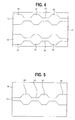
- FIG. 4 is a top view of the moveable punch support of the strapping machine shown in FIG. 1 having two progressive punches mounted thereto;
- FIG. 5 is a top view of the fixed support of the strapping machine shown in FIG. 1 and the progressive punch mounted thereto; and
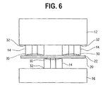
- FIG. 6 illustrates movable and fixed punch supports and their respective punches acting in conjunction with one another with a portion of strap material.
-
- The invention may be used in a variety of strapping machines or tools (also referred to as strappers) such as the
exemplary strapper 2 illustrated in FIG. 1. The illustratedstrapper 2 includes a strapping machine body 4, a gripper (not shown),feed wheel 6 and accompanying feed lever (not shown) . Thestrapper 2 further includes a cutter (not shown) and accompanying actuatinglever 10, and ajaw assembly 11. Thejaw assembly 11 includes first and second punch supports 12, 16.Punches 14 havingpunching heads supports - Referring now to FIGS. 4-6, the
second support 16 is fixed and includes onepunch 14. Thefirst punch support 12 is moveable toward and away from thefixed support 16 and includes twopunches 14. - Typically, manual strapping machines are used to strap several groups of articles (e.g., a load) together. In that many of these machines or tools are portable, they are known to be used at, for example, a logging site or warehouse facility. Operators must repeatedly apply a force to the actuation lever to effect a seal each time articles are strapped together. This inevitably results in operator fatigue. It is desirable, therefore, to provide a sealing element or punch that allows a seal of sufficient strength to be formed while reducing the amount or magnitude of force required. This can be accomplished by minimizing sealing head surface area that initially engages the strap, thus concentrating the force and increasing the magnitude of pressure applied to the strap.
- The present
progressive punch 14 is used in a strapper and is configured to effect minimum punch surface area engagement with the strap at engagement. Referring now to FIG. 2, there is shown one embodiment of aprogressive punch 14 embodying the principles of the present invention. Thepunch 14 includes first, second andthird punching heads punch 14 defines a height axis (h), a length axis (1) and a width axis (w). Eachpunching head cutting edge 30 and abase 32 portion. In the illustrated embodiment, thepunching heads respective bases 32 are a unitary element and theircutting edges 30 are contiguous with one another. - Referring again to FIG. 2, each punching
head peripheral point cutting edge 30. The outermost peripheral point of each punching head is linearly spaced with respect to corresponding outermost peripheral points of the other punching heads. That is, the height of each punching head h24, h26, h28 relative to a plane Pm perpendicular to the direction of movement, as indicated at M, of thepunch 14 is different from the height h24, h26, h28 of each other head. In this manner, as will be described herein, thepunching heads strap strapper 2 is actuated to form the strap seal. - The direction of linear spacing between the head heights h24, h26, h28 is substantially along the height axis h of the
punch 14. For example, when the illustratedstrapper 2 is horizontally oriented, as shown in FIG. 1, the linear spacing between head heights h24, h26, h28 would be vertical. - The linear spacing allows less than all of the
punching heads - It is to be understood that although the embodiment illustrated in FIG. 2 shows three punching
heads punch 14 is shown having the punch head heights h24, h26, h28 being serially stepped (that is, h24 being greater than h26 which is greater than h28), the order of these heights can be varied and arranged in any manner. - As seen in FIG. 2, the punching heads 24,26,28 have an arcuate cutting edge profile. The punching heads 24,26,28 are substantially defined by linearly arranged,
octagons octagonal bodies - Referring to FIGS. 4-6, two
punches 14 are mounted to themoveable punch support 12 at theirrespective bases 32, and onepunch 14 is mounted to the fixedsupport 16 at itsrespective base 32. FIG. 6 illustrates the arrangement and cooperation of the twopunches 14 of themovable support 12 with thepunch 14 of the fixedsupport 16, as when an operator applies a force to theactuating lever 10, causing the movable support 12 (and its punches 14) to move into engagement with the fixed support 16 (and its punch 14) to engage the strap. As can be seen from FIG. 6, as themovable support 12 moves into contact with the fixed support 16 (with the strap therebetween), therespective punches 14 of themovable support 16 and the fixedsupport 12 overlap one another. In this manner, thepunch 14 of the fixedsupport 12 engages the strap in between the punches of themovable support 16. - In use, a
first end 18 of strapping material (S), which can be stored on a roll, is passed around the load L and is fed into thejaws 11, between thefirst punch support 12 andsecond punch support 16 and is held between thefeed wheel 6 and the gripper (not shown). This results in an overlap of strapping material (S) so thefirst end 18, which is held by the gripper, forms alower layer 20 of strapping material. Anupper layer 22 of strapping material, which may still be connected to the roll, overlaps thelower layer 20. The feed lever (not shown) is actuated which in turn rotates thefeed wheel 6, to tighten the strap around the load L. The strap is then sealed to itself and is cut at theupper layer 22 from the roll by the cutter. - When the operator applies force via the
lever 10, thecutting edge 30 of thepunch 14 of the fixedsupport 16 engage upwardly on a lower portion of thelower strap 20 and the cutting edges 30 of thepunches 14 of themovable support 12 engage downwardly on an upper portion of theupper strap 22. As shown in FIG. 6, this causes thepunches 14, which are attached to thesupports upper layer 22 of strap material onto thelower layer 20 of the strap material and effect a seal.
Claims (10)
- A punch (14,16) for use with an associated strapping tool for forming a seal between two portions of strapping material, the strapping tool including a jaw having a fixed support and a movable support movable toward and away from the fixed support in a direction of movement to engage the two portion of strapping material therebetween, the punch (14,16) comprising:at least two punching heads (24,26,28) fixedly attached to one another, a first punching head (24) having a height defined by a distance between an outermost peripheral point (34) of the first punching head (24) and a plane perpendicular to the direction of movement, and a second punching head (26) having a height defined by a distance between an outermost peripheral point of the second punching head (36) and the plane perpendicular to the direction of movement, wherein the height of the first punching head (24) is different from the height of the second punching head (26).
- A punch according to claim 1, further including a third punching head (28), wherein the third punching head (28) is fixedly attached to at least one of the first and second punching heads (24,26) and wherein the third punching head (28) has a height defined by a distance between an outermost peripheral point of the third punching head (38) and the plane perpendicular to the direction of movement, the height of the third punching head (28) being different from at least one of the first and second punching head (24,26) heights.
- A punch according to claim 2, wherein the third punching head height is different from both of the first and second punching head heights.
- A punch according to any one of the preceding claims, wherein the punching heads (24,26,28) include a cutting edge (30), the cutting edge (30) having an arcuate profile.
- A punch according to any one of the preceding claims, wherein the punch is formed as a unitary element.
- A jaw assembly for use in a strapping tool for forming a seal between two portions of strapping material, the jaw assembly comprising:a fixed support (16);a movable support (12);an actuating lever (10) operably connected to the movable support (12) for moving the movable support (12) toward and away from the fixed support (16) in a direction of movement for engaging the strapping material;a fixed punch (16) carried by the fixed support; and,a movable punch (14) carried by the movable support (12) for movement toward and away from the fixed punch (16),each the fixed punch (16) and the movable punch (14) including a punch in accordance with any one of the preceding claims.
- A jaw assembly according to claim 6, wherein the movable support (12) includes a pair of movable punches (14) fixedly mounted to the support (12) relative to one another.
- A jaw assembly according to claim 7, wherein the fixed punch (16) is disposed such that when fixed and movable punches (14,16) engage the strap portions therebetween, cutting edges of the fixed punch (16) overlie cutting edges of the movable punches (14).
- A jaw assembly according to claim 6, 7 or 8, wherein an outermost peripheral point of each first punching head is linearly spaced with respect to a corresponding outermost peripheral point of each respective second punching head and wherein an outermost peripheral point of each third punching head is linearly spaced with respect to outermost peripheral points of respective first and second punching heads, the directions of linear spacing being substantially defined by height axes of the respective punches.
- A strapping tool for forming a seal between two portions of strapping material, comprising a jaw assembly in accordance with any one of claims 6, 7, 8 or 9.
Applications Claiming Priority (2)
| Application Number | Priority Date | Filing Date | Title |
|---|---|---|---|
| US09/812,156 US6554030B2 (en) | 2001-03-19 | 2001-03-19 | Progressive punch |
| US812156 | 2001-03-19 |
Publications (1)
| Publication Number | Publication Date |
|---|---|
| EP1243510A1 true EP1243510A1 (en) | 2002-09-25 |
Family
ID=25208689
Family Applications (1)
| Application Number | Title | Priority Date | Filing Date |
|---|---|---|---|
| EP02251695A Withdrawn EP1243510A1 (en) | 2001-03-19 | 2002-03-11 | Punch for strapping tool |
Country Status (10)
| Country | Link |
|---|---|
| US (1) | US6554030B2 (en) |
| EP (1) | EP1243510A1 (en) |
| JP (1) | JP2002332007A (en) |
| KR (1) | KR100807674B1 (en) |
| CN (1) | CN1228210C (en) |
| AU (1) | AU761506B2 (en) |
| CA (1) | CA2376537C (en) |
| MX (1) | MXPA02002630A (en) |
| NZ (1) | NZ517581A (en) |
| TW (1) | TW521055B (en) |
Cited By (1)
| Publication number | Priority date | Publication date | Assignee | Title |
|---|---|---|---|---|
| EP1857367A3 (en) * | 2006-05-09 | 2008-11-19 | Illinois Tool Works Inc. | Reduced force sealless connection mechanism |
Families Citing this family (7)
| Publication number | Priority date | Publication date | Assignee | Title |
|---|---|---|---|---|
| US20080166081A1 (en) * | 2007-01-10 | 2008-07-10 | Illinois Tool Works, Inc. | System and method for retaining rollers of a full complement needle bearing |
| US9221567B2 (en) | 2012-01-25 | 2015-12-29 | Southern Bracing Systems Enterprises, Llc | Systems, methods, and devices for tensioning straps |
| US9932135B2 (en) | 2012-09-24 | 2018-04-03 | Signode Industrial Group Llc | Strapping device |
| US10723035B1 (en) | 2014-07-15 | 2020-07-28 | Southwire Company, Llc | Punch |
| US11174051B2 (en) | 2019-02-15 | 2021-11-16 | Samuel, Son & Co. (Usa) Inc. | Hand held strapping tool |
| CN112158383B (en) * | 2020-10-12 | 2024-05-10 | 北京信息科技大学 | Locking device for bundling and locking steel coil |
| US12397943B2 (en) | 2022-11-29 | 2025-08-26 | Samuel, Son & Co. (Usa) Inc. | Handheld strapping device |
Citations (2)
| Publication number | Priority date | Publication date | Assignee | Title |
|---|---|---|---|---|
| GB457426A (en) * | 1935-02-02 | 1936-11-27 | Arthur Van Aerden | Apparatus for fastening steel strapping bands, and sealed band produced thereby |
| DE1225543B (en) * | 1963-08-28 | 1966-09-22 | Timmerbeil Erich | Device for joining the ends of straps |
Family Cites Families (3)
| Publication number | Priority date | Publication date | Assignee | Title |
|---|---|---|---|---|
| US789193A (en) * | 1903-04-27 | 1905-05-09 | Western Electric Co | Splicing-tool. |
| US2229786A (en) * | 1938-04-13 | 1941-01-28 | Packers Supply Company Ltd | Strip tensioning apparatus |
| US5097874A (en) * | 1991-04-07 | 1992-03-24 | Signode Corporation | Strapping head with strap tail-flattening capability |
-
2001
- 2001-03-19 US US09/812,156 patent/US6554030B2/en not_active Expired - Lifetime
-
2002
- 2002-02-26 TW TW091103493A patent/TW521055B/en not_active IP Right Cessation
- 2002-02-28 KR KR1020020011004A patent/KR100807674B1/en not_active Expired - Fee Related
- 2002-03-04 NZ NZ517581A patent/NZ517581A/en unknown
- 2002-03-11 EP EP02251695A patent/EP1243510A1/en not_active Withdrawn
- 2002-03-11 CN CNB021070385A patent/CN1228210C/en not_active Expired - Fee Related
- 2002-03-11 MX MXPA02002630A patent/MXPA02002630A/en not_active Application Discontinuation
- 2002-03-12 CA CA002376537A patent/CA2376537C/en not_active Expired - Lifetime
- 2002-03-19 JP JP2002076006A patent/JP2002332007A/en active Pending
- 2002-03-19 AU AU27464/02A patent/AU761506B2/en not_active Ceased
Patent Citations (2)
| Publication number | Priority date | Publication date | Assignee | Title |
|---|---|---|---|---|
| GB457426A (en) * | 1935-02-02 | 1936-11-27 | Arthur Van Aerden | Apparatus for fastening steel strapping bands, and sealed band produced thereby |
| DE1225543B (en) * | 1963-08-28 | 1966-09-22 | Timmerbeil Erich | Device for joining the ends of straps |
Cited By (1)
| Publication number | Priority date | Publication date | Assignee | Title |
|---|---|---|---|---|
| EP1857367A3 (en) * | 2006-05-09 | 2008-11-19 | Illinois Tool Works Inc. | Reduced force sealless connection mechanism |
Also Published As
| Publication number | Publication date |
|---|---|
| CN1375429A (en) | 2002-10-23 |
| JP2002332007A (en) | 2002-11-22 |
| KR100807674B1 (en) | 2008-02-28 |
| CA2376537A1 (en) | 2002-09-19 |
| NZ517581A (en) | 2003-10-31 |
| US20020129501A1 (en) | 2002-09-19 |
| CA2376537C (en) | 2007-05-29 |
| MXPA02002630A (en) | 2007-04-24 |
| AU761506B2 (en) | 2003-06-05 |
| US6554030B2 (en) | 2003-04-29 |
| KR20020074387A (en) | 2002-09-30 |
| CN1228210C (en) | 2005-11-23 |
| TW521055B (en) | 2003-02-21 |
| AU2746402A (en) | 2002-09-26 |
Similar Documents
| Publication | Publication Date | Title |
|---|---|---|
| KR100777331B1 (en) | Strapping machine for forming a seal between two portions of strapping material and cutting an upper layer of the strapping material | |
| EP0949146B1 (en) | Strap welding tool | |
| US5942061A (en) | Cam operated strap welding tool and method therefor | |
| US6554030B2 (en) | Progressive punch | |
| EP1857367B1 (en) | Reduced force sealless connection mechanism | |
| JPH01118319A (en) | Hemming method and device | |
| US6698460B2 (en) | Strapping unit having replaceable wearing parts | |
| US3743148A (en) | Wafer breaker | |
| CA2378293C (en) | Strap sealer with fast-acting dual action piston | |
| US3021876A (en) | Strapping tool | |
| KR100239970B1 (en) | Steel strapping tool cutter | |
| US3333608A (en) | Tightening and closure device for band-like closure hoops | |
| US5489090A (en) | Clamping and shaping tool | |
| CA2200256C (en) | Band clamping machine | |
| FI57563C (en) | BANDNINGSMASKIN | |
| CA2376454C (en) | Strapper with feed wheel cleaning device | |
| JPS62292420A (en) | Contact bonding machine for cold joining of conveyor belt | |
| NZ522961A (en) | Variable strap width accommodating assembly for a strapping machine |
Legal Events
| Date | Code | Title | Description |
|---|---|---|---|
| PUAI | Public reference made under article 153(3) epc to a published international application that has entered the european phase |
Free format text: ORIGINAL CODE: 0009012 |
|
| AK | Designated contracting states |
Kind code of ref document: A1 Designated state(s): AT BE CH CY DE DK ES FI FR GB GR IE IT LI LU MC NL PT SE TR |
|
| AX | Request for extension of the european patent |
Free format text: AL;LT;LV;MK;RO;SI |
|
| 17P | Request for examination filed |
Effective date: 20030318 |
|
| AKX | Designation fees paid |
Designated state(s): AT BE CH CY DE DK ES FI FR GB GR IE IT LI LU MC NL PT SE TR |
|
| STAA | Information on the status of an ep patent application or granted ep patent |
Free format text: STATUS: THE APPLICATION HAS BEEN WITHDRAWN |
|
| 18W | Application withdrawn |
Effective date: 20041123 |