EP1243508A1 - Strapping tool - Google Patents
Strapping tool Download PDFInfo
- Publication number
- EP1243508A1 EP1243508A1 EP02251694A EP02251694A EP1243508A1 EP 1243508 A1 EP1243508 A1 EP 1243508A1 EP 02251694 A EP02251694 A EP 02251694A EP 02251694 A EP02251694 A EP 02251694A EP 1243508 A1 EP1243508 A1 EP 1243508A1
- Authority
- EP
- European Patent Office
- Prior art keywords
- feed wheel
- strapping
- assembly
- sub
- cleaning element
- Prior art date
- Legal status (The legal status is an assumption and is not a legal conclusion. Google has not performed a legal analysis and makes no representation as to the accuracy of the status listed.)
- Withdrawn
Links
Images
Classifications
-
- B—PERFORMING OPERATIONS; TRANSPORTING
- B08—CLEANING
- B08B—CLEANING IN GENERAL; PREVENTION OF FOULING IN GENERAL
- B08B1/00—Cleaning by methods involving the use of tools
- B08B1/30—Cleaning by methods involving the use of tools by movement of cleaning members over a surface
- B08B1/32—Cleaning by methods involving the use of tools by movement of cleaning members over a surface using rotary cleaning members
- B08B1/34—Cleaning by methods involving the use of tools by movement of cleaning members over a surface using rotary cleaning members rotating about an axis parallel to the surface
-
- B—PERFORMING OPERATIONS; TRANSPORTING
- B08—CLEANING
- B08B—CLEANING IN GENERAL; PREVENTION OF FOULING IN GENERAL
- B08B1/00—Cleaning by methods involving the use of tools
- B08B1/10—Cleaning by methods involving the use of tools characterised by the type of cleaning tool
- B08B1/12—Brushes
-
- B—PERFORMING OPERATIONS; TRANSPORTING
- B65—CONVEYING; PACKING; STORING; HANDLING THIN OR FILAMENTARY MATERIAL
- B65B—MACHINES, APPARATUS OR DEVICES FOR, OR METHODS OF, PACKAGING ARTICLES OR MATERIALS; UNPACKING
- B65B13/00—Bundling articles
- B65B13/02—Applying and securing binding material around articles or groups of articles, e.g. using strings, wires, strips, bands or tapes
- B65B13/025—Hand-held tools
-
- B—PERFORMING OPERATIONS; TRANSPORTING
- B65—CONVEYING; PACKING; STORING; HANDLING THIN OR FILAMENTARY MATERIAL
- B65B—MACHINES, APPARATUS OR DEVICES FOR, OR METHODS OF, PACKAGING ARTICLES OR MATERIALS; UNPACKING
- B65B13/00—Bundling articles
- B65B13/18—Details of, or auxiliary devices used in, bundling machines or bundling tools
- B65B13/185—Details of tools
Definitions
- Strapping machines or strappers are well known in the art. These machines are used for strapping articles together with strapping material. Strapping material is offered in a variety of sizes and materials and is generally stored on a roll. Conventional strapping materials include steel and plastic.
- a free end of strapping material is passed around the articles until there is an overlap between the free end and the strapping material still connected to the roll.
- the overlapping portion of strapping material is placed between jaws of a strapping machine and the free end of the strapping material is fixed in place by a gripper portion and feed wheel of the machine.
- the material is tightened or tensioned around the load to a desired tension. This is accomplished by operating a feed lever that rotates a feed wheel to pull back or tension the strapping material.
- a typical feed wheel includes serrations or grooves formed in the surface of the wheel to increase the friction developed between the wheel and the strap.
- a typical strapping machine includes sealing heads for sealing the free end of the strapping material onto itself, around the load.
- a handle is rotated which applies a force to cause a punch or sealing head to press down against the strap to seal the strap to itself.
- the strapping material still connected to the roll is cut by a cutter of the strapping machine. This completes one strapping operation.
- This type of seal which is effected by sealing the strap to itself, differs from those strappers that position a separate piece of material around the tensioned strap.
- steel strapping is provided with a coating, such as epoxy or paint.
- a coating such as epoxy or paint.
- the bare strapping is often formed from common carbon steel materials, the coating prevents corrosion which could, if left unabated, compromise the integrity of the strap.
- a portion of the coating can be removed (e.g., ground) from the strap. This coating debris can become lodged in the feed wheel serrations or grooves thus reducing the friction developed between the wheel and the strap.
- a feed wheel cleaning arrangement that is effectively used with a strapping machine feed wheel as the strap is tensioned around the load.
- a feed wheel cleaning arrangement readily removes accumulated dirt or debris from the feed wheel so that an acceptable amount of friction can be developed between the feed wheel and the strap.
- a cleaning arrangement is in place during strapping machine operation and is readily replaced as necessary.
- a strapping tool forms a seal between two portions of associated strapping material, which strapping material is tensioned prior to forming the seal.
- the tool includes a strapping machine body and a sub-assembly operably coupled to the body.
- a feed wheel is carried by the sub-assembly and is rotatable within the sub-assembly. The strapping material is tensioned by engagement of the rotating feed wheel with the strapping material.
- a feed lever is operably connected to the sub-assembly and to the feed wheel for rotating the feed wheel.
- a cleaning element is supported by the sub-assembly.
- the cleaning element is disposed for continuous contact with the rotating feed wheel.
- the cleaning element includes a brush portion and a handle portion.
- the handle portion is formed from a flexible wire.
- the cleaning element is configured to be readily removed, e.g., pulled by the handle, from the strapping tool for replacement.
- a present strapping tool sub-assembly includes a pair of spaced apart, opposing walls with the feed wheel positioned between the walls. Each wall includes an opening therein at a periphery of the feed wheel.
- the cleaning element is disposed within the sub-assembly, in the openings with the brush portion in contact with the feed wheel. In this manner, the brush portion remains in contact with the feed wheel during strapping tool operation.
- the feed wheel is configured to rotate counter-clockwise and the cleaning element is positioned along an anterior side of the feed wheel.
- the feed wheel can be configured to rotate clockwise and the cleaning element can be positioned along a posterior side of the feed wheel.
- the invention may be used in a variety of strapping machines or tools (also referred to as strappers) such as the exemplary strapper 2 illustrated in FIG. 1, the construction and operation of which will be readily recognized by those skilled in the art.
- the illustrated strapper 2 includes a sub-assembly 4 operably coupled to a strapping machine body 6.
- a cutter (not shown), a gripper (not shown), and a jaw assembly 8 are positioned within the strapping machine body 6.
- the jaw assembly 8 includes a first, movable support 14 and a second, fixed support 16. Sealing elements 18 are carried by the supports 14, 16 for forming a seal in the strap S.
- a feed wheel 20 and cleaning element 24 are positioned within the sub-assembly 4.
- the feed wheel 20 is actuated by rotating a feed lever 22.
- Those skilled in the art will recognize and appreciate the various strapping machine configurations, which may include grippers, feed wheels and/or accompanying levers and cutters of various types, or other structures used to grip a strap, tension a strap around a load and cut the strap, with which the present cleaning element 24 can be used.
- a first or free end of the strapping material S is passed around a load L and fed between the movable and fixed supports 14, 16.
- the free end of the strap S is gripped by the gripper, which results in an overlap of strapping material 5, with the free end forming a lower layer 26 of strapping material S.
- An upper layer 28 of strap S overlaps the lower layer 26.
- the feed lever 22 is then operated (e.g., rotated) which in turn rotates the feed wheel 20, tightening the strap S around the load.
- the feed lever 22 when the feed lever 22 is actuated the entire sub-assembly 4 pivots and the feed wheel 20 rotates to tension the strap S.
- the strap S is then sealed to itself, and cut.
- a handle 23 can be used to hold the strapper 2 when actuating the feed lever 22.
- many known strap materials are provided with a corrosion-resistant coating.
- the coating may rub off of the strap or may be ground off of the strap by the engagement of the wheel 20 and strap 5, causing debris.
- coating debris as well as other dirt and debris generally indicated as D, can accumulate on the feed wheel 20.
- this dirt and debris D is cleaned from the wheel 20 to ensure efficient feed wheel 20 operation.
- the present cleaning element 24 allows feed wheel 20 cleaning without timely or costly maintenance.
- the cleaning element 24 includes a brush portion 30 integral with a flexible wire handle 32. Openings 34, 36 are formed in the walls 42, 44 of the sub-assembly 4. A first end 46 of the element 24 is inserted into and through opening 34 and is urged wall 42. The element 24 is further urged through opening 36 in wall 44. The cleaning element 24 is readily removed by pulling on the handle 32 until is it free of walls 42,44.
- the cleaning element 24 may be attached to the sub-assembly 4, by, for example, using a brush that has first and second shafts formed on both sides of the brush, and positioning the shafts within shaft apertures formed within internal sides of the sub-assembly walls 42, 44. In such an embodiment, the cleaning element 24 may not be as readily removable.
- the feed wheel 20 of FIG. 2 includes a main body portion 48 with grooves or serrations, indicated at 50 formed thereon.
- the wheel is mounted to the sub-assembly by a shaft having shaft portions 52,54 extending from the wheel 20 that are positioned in the shaft apertures 38,40 in the sub-assembly 4 to allow for the feed wheel 20 to rotate upon actuation by the feed lever 22 (FIG. 1).
- the cleaning element 24 is positioned along a posterior side of and above (as indicated generally at 60) the feed wheel 20. In this manner, as the cleaning element 24 contacts the feed wheel 20 (which rotates in a counterclockwise direction), the brush 30 directs dust and debris D away from the feed wheel 20.
- the cleaning element 24 can be positioned along an anterior side (as indicated generally at 62) of the feed wheel 20, and will have the same result for feed wheels that are configured to rotate in a clockwise direction.
Landscapes
- Engineering & Computer Science (AREA)
- Mechanical Engineering (AREA)
- Basic Packing Technique (AREA)
- Registering, Tensioning, Guiding Webs, And Rollers Therefor (AREA)
- Automobile Manufacture Line, Endless Track Vehicle, Trailer (AREA)
Abstract
A strapping tool (2) includes an integral, removable
cleaning element (24). The strapping tool (2) forms a seal
between two portions of associated strapping material (S),
which strapping material (S) is tensioned by a feed wheel
(20) prior to forming the seal. The tool (2) includes a
strapping machine body (6), a sub-assembly (4) operably
coupled to the strapping machine body (6). A feed wheel
(20) is carried by the sub-assembly (4) and is rotatable
within the sub-assembly (4). A feed lever (22) is operably
connected to the sub-assembly (4) and to the feed wheel
(20) for rotating the feed wheel (20). A cleaning element
(24) is supported by the sub-assembly (4) and is disposed
for continuous contact with the rotating feed wheel (20).
Description
- Strapping machines or strappers are well known in the art. These machines are used for strapping articles together with strapping material. Strapping material is offered in a variety of sizes and materials and is generally stored on a roll. Conventional strapping materials include steel and plastic.
- Typically, a free end of strapping material is passed around the articles until there is an overlap between the free end and the strapping material still connected to the roll. The overlapping portion of strapping material is placed between jaws of a strapping machine and the free end of the strapping material is fixed in place by a gripper portion and feed wheel of the machine. After the strapping material is fixed, the material is tightened or tensioned around the load to a desired tension. This is accomplished by operating a feed lever that rotates a feed wheel to pull back or tension the strapping material. A typical feed wheel includes serrations or grooves formed in the surface of the wheel to increase the friction developed between the wheel and the strap.
- A typical strapping machine includes sealing heads for sealing the free end of the strapping material onto itself, around the load. Typically, in manual (i.e., hand-operated) strapping machines, a handle is rotated which applies a force to cause a punch or sealing head to press down against the strap to seal the strap to itself. After the strapping material is sealed, the strapping material still connected to the roll is cut by a cutter of the strapping machine. This completes one strapping operation. This type of seal, which is effected by sealing the strap to itself, differs from those strappers that position a separate piece of material around the tensioned strap.
- Typically, steel strapping is provided with a coating, such as epoxy or paint. In that the bare strapping is often formed from common carbon steel materials, the coating prevents corrosion which could, if left unabated, compromise the integrity of the strap.
- During the tensioning operation, when the feed wheel contacts and "pulls" the strap, a portion of the coating can be removed (e.g., ground) from the strap. This coating debris can become lodged in the feed wheel serrations or grooves thus reducing the friction developed between the wheel and the strap.
- In addition, other dirt or debris can accumulate on the feed wheel while tightening or tensioning the strap. The accumulated debris may "clog up" the feed wheel, necessitating feed wheel maintenance, which may be time consuming and expensive.
- Accordingly, there exists a need for a feed wheel cleaning arrangement that is effectively used with a strapping machine feed wheel as the strap is tensioned around the load. Desirably, such a feed wheel cleaning arrangement readily removes accumulated dirt or debris from the feed wheel so that an acceptable amount of friction can be developed between the feed wheel and the strap. Most desirably, such a cleaning arrangement is in place during strapping machine operation and is readily replaced as necessary.
- A strapping tool forms a seal between two portions of associated strapping material, which strapping material is tensioned prior to forming the seal. The tool includes a strapping machine body and a sub-assembly operably coupled to the body. A feed wheel is carried by the sub-assembly and is rotatable within the sub-assembly. The strapping material is tensioned by engagement of the rotating feed wheel with the strapping material. A feed lever is operably connected to the sub-assembly and to the feed wheel for rotating the feed wheel.
- A cleaning element is supported by the sub-assembly. The cleaning element is disposed for continuous contact with the rotating feed wheel. In a current embodiment, the cleaning element includes a brush portion and a handle portion. Preferably, the handle portion is formed from a flexible wire. The cleaning element is configured to be readily removed, e.g., pulled by the handle, from the strapping tool for replacement.
- A present strapping tool sub-assembly includes a pair of spaced apart, opposing walls with the feed wheel positioned between the walls. Each wall includes an opening therein at a periphery of the feed wheel. The cleaning element is disposed within the sub-assembly, in the openings with the brush portion in contact with the feed wheel. In this manner, the brush portion remains in contact with the feed wheel during strapping tool operation.
- In a present strapping tool, the feed wheel is configured to rotate counter-clockwise and the cleaning element is positioned along an anterior side of the feed wheel. Alternately, the feed wheel can be configured to rotate clockwise and the cleaning element can be positioned along a posterior side of the feed wheel.
- A particular embodiment in accordance with this invention will now be described with reference to the accompanying drawings; in which:-
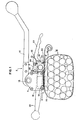
- FIG. 1 illustrates a strapping machine having a cleaning device; and,
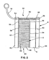
- FIG. 2 illustrates a side view of a configuration including a feed wheel, a sub-assembly, and the cleaning device of FIG. 1.
-
- The invention may be used in a variety of strapping machines or tools (also referred to as strappers) such as the
exemplary strapper 2 illustrated in FIG. 1, the construction and operation of which will be readily recognized by those skilled in the art. The illustratedstrapper 2 includes asub-assembly 4 operably coupled to a strappingmachine body 6. A cutter (not shown), a gripper (not shown), and ajaw assembly 8 are positioned within the strappingmachine body 6. An accompanying actuatinglever 10, which is configured to rotate about aneccentric shaft 12, actuates the cutter and jaw assembly S. Thejaw assembly 8 includes a first,movable support 14 and a second, fixedsupport 16.Sealing elements 18 are carried by thesupports - A
feed wheel 20 and cleaningelement 24 are positioned within thesub-assembly 4. Thefeed wheel 20 is actuated by rotating afeed lever 22. Those skilled in the art will recognize and appreciate the various strapping machine configurations, which may include grippers, feed wheels and/or accompanying levers and cutters of various types, or other structures used to grip a strap, tension a strap around a load and cut the strap, with which thepresent cleaning element 24 can be used. - In use of the
strapper 2 of FIG. 1, typically, a first or free end of the strapping material S is passed around a load L and fed between the movable and fixedsupports upper layer 28 of strap S overlaps the lower layer 26. Thefeed lever 22 is then operated (e.g., rotated) which in turn rotates thefeed wheel 20, tightening the strap S around the load. In the illustratedstrapper 2, when thefeed lever 22 is actuated theentire sub-assembly 4 pivots and thefeed wheel 20 rotates to tension the strap S. The strap S is then sealed to itself, and cut. Ahandle 23 can be used to hold thestrapper 2 when actuating thefeed lever 22. - As set forth above, many known strap materials are provided with a corrosion-resistant coating. The coating may rub off of the strap or may be ground off of the strap by the engagement of the
wheel 20 and strap 5, causing debris. To this end, when tightening the strap S around the load L, coating debris as well as other dirt and debris, generally indicated as D, can accumulate on thefeed wheel 20. Desirably, this dirt and debris D is cleaned from thewheel 20 to ensureefficient feed wheel 20 operation. Thepresent cleaning element 24 allowsfeed wheel 20 cleaning without timely or costly maintenance. - Referring to FIG. 2, the cleaning
element 24 includes abrush portion 30 integral with aflexible wire handle 32.Openings walls sub-assembly 4. Afirst end 46 of theelement 24 is inserted into and through opening 34 and is urgedwall 42. Theelement 24 is further urged throughopening 36 inwall 44. The cleaningelement 24 is readily removed by pulling on thehandle 32 until is it free ofwalls - Those skilled in the art will recognize that the
cleaning element 24 may be attached to thesub-assembly 4, by, for example, using a brush that has first and second shafts formed on both sides of the brush, and positioning the shafts within shaft apertures formed within internal sides of thesub-assembly walls element 24 may not be as readily removable. - The
feed wheel 20 of FIG. 2 includes amain body portion 48 with grooves or serrations, indicated at 50 formed thereon. The wheel is mounted to the sub-assembly by a shaft havingshaft portions wheel 20 that are positioned in theshaft apertures sub-assembly 4 to allow for thefeed wheel 20 to rotate upon actuation by the feed lever 22 (FIG. 1). - Preferably, as shown in FIG. 1, the cleaning
element 24 is positioned along a posterior side of and above (as indicated generally at 60) thefeed wheel 20. In this manner, as thecleaning element 24 contacts the feed wheel 20 (which rotates in a counterclockwise direction), thebrush 30 directs dust and debris D away from thefeed wheel 20. Those skilled in the art will recognize that thecleaning element 24 can be positioned along an anterior side (as indicated generally at 62) of thefeed wheel 20, and will have the same result for feed wheels that are configured to rotate in a clockwise direction.
Claims (8)
- A strapping tool (2) for forming a seal between two portions of associated strapping material, the strapping material being tensioned prior to forming the seal, the tool comprising:a strapping machine body (6);a sub-assembly (4) operably coupled to the strapping machine body (6) ;a feed wheel (20) carried by the sub-assembly (4), the feed wheel (20) being rotatable within the sub-assembly (4);a feed lever (22) operably connected to the sub-assembly (4) and to the feed wheel (20) for rotating the feed wheel (20), wherein the strapping material is tensioned by engagement of the rotating feed wheel (20) with the strapping material; and,a cleaning element (24) supported by the sub-assembly (4), wherein the cleaning element (24) is disposed for continuous contact with the rotating feed wheel (20).
- A strapping tool according to claim 1, wherein the sub-assembly (4) includes a pair of spaced apart, opposing walls (42,44) with the feed wheel (20) positioned between them, and wherein each wall (42,44) includes an opening (34,36) therein at a periphery of the feed wheel (20) and wherein the cleaning element (24) is disposed within the sub-assembly (4), in the openings (34,36).
- A strapping tool (2) for forming a seal between two portions of associated strapping material, the strapping tool material being tensioned prior to forming the seal, the strapping tool comprising:a strapping machine body (6);a cleaning element (24) supported by the strapping machine body (6) ;a feed wheel (20); and,a feed lever (22), the feed wheel (20) being operably connected to the feed lever (22), the feed lever (22) configured to have a first vertical position and a second vertical position in which the feed wheel (20) engages the strapping material to exert a tension in the strapping material, wherein the feed wheel (20) engages the cleaning element (24) when the feed lever is in the second vertical position.
- A strapping tool according to claim 3, wherein the feed wheel (20) is carried between spaced apart mounting members (44,46) and wherein the cleaning element (24) is disposed in openings (34,36) in the mounting members (44,46) to contact the feed wheel (20) at a periphery thereof.
- A strapping tool according to any one of the preceding claims, wherein the cleaning device (24) includes a brush portion (30) and a handle portion (32).
- A strapping tool according to claim 5, wherein the handle portion (32) is formed from a flexible wire.
- A strapping tool according to any one of the preceding claims, wherein the cleaning element (24) is removable sub-assembly.
- A strapping tool according to any one of the preceding claims, wherein the feed wheel (20) is configured to rotate clockwise and the cleaning element (24) is positioned along an anterior side of the feed wheel (20), or wherein the feed wheel (20) is configured to rotate counter-clockwise and the cleaning element (24) is positioned along a posterior side of the feed wheel (20).
Applications Claiming Priority (2)
| Application Number | Priority Date | Filing Date | Title |
|---|---|---|---|
| US812164 | 1985-12-23 | ||
| US09/812,164 US6550375B2 (en) | 2001-03-19 | 2001-03-19 | Strapper with feed wheel cleaning device |
Publications (1)
| Publication Number | Publication Date |
|---|---|
| EP1243508A1 true EP1243508A1 (en) | 2002-09-25 |
Family
ID=25208718
Family Applications (1)
| Application Number | Title | Priority Date | Filing Date |
|---|---|---|---|
| EP02251694A Withdrawn EP1243508A1 (en) | 2001-03-19 | 2002-03-11 | Strapping tool |
Country Status (10)
| Country | Link |
|---|---|
| US (1) | US6550375B2 (en) |
| EP (1) | EP1243508A1 (en) |
| JP (1) | JP4261115B2 (en) |
| KR (1) | KR20020074385A (en) |
| CN (1) | CN1207170C (en) |
| AU (1) | AU763939B2 (en) |
| CA (1) | CA2376454C (en) |
| MX (1) | MXPA02002753A (en) |
| NZ (1) | NZ517582A (en) |
| TW (1) | TW518302B (en) |
Families Citing this family (5)
| Publication number | Priority date | Publication date | Assignee | Title |
|---|---|---|---|---|
| WO2003107282A2 (en) * | 2002-06-13 | 2003-12-24 | Cummins-Allison Corp. | Currency processing and strapping systems and methods for using the same |
| US7779982B2 (en) * | 2006-09-07 | 2010-08-24 | Cummins-Allison Corp. | Currency processing and strapping systems and methods |
| US7970526B2 (en) * | 2009-01-05 | 2011-06-28 | Caterpillar Inc. | Intensifier quill for fuel injector and fuel system using same |
| KR102315934B1 (en) | 2020-12-14 | 2021-10-22 | 장근철 | Manual packaging tool capable of sealing metal clip with one handle |
| CN117699117B (en) * | 2024-02-05 | 2024-04-30 | 安徽卓彧工业制造有限公司 | Handheld plastic steel belt packer |
Citations (2)
| Publication number | Priority date | Publication date | Assignee | Title |
|---|---|---|---|---|
| US5392821A (en) * | 1993-10-08 | 1995-02-28 | Signode Corporation | Strapping tool with mechanism for admitting, retaining, and releasing steel strap |
| DE10026198A1 (en) * | 2000-05-26 | 2001-11-29 | Cyklop Gmbh | Device for tensioning and closing plastic strapping |
Family Cites Families (4)
| Publication number | Priority date | Publication date | Assignee | Title |
|---|---|---|---|---|
| US3284049A (en) * | 1965-03-31 | 1966-11-08 | Signode Corp | Feed wheel drive mechanism for strapping tools |
| US3944460A (en) * | 1972-12-14 | 1976-03-16 | Interlake, Inc. | Combination strapping tool for plastic strap |
| CH684251A5 (en) * | 1991-06-07 | 1994-08-15 | Fromm Holding Ag | Strapping tool. |
| US6073294A (en) * | 1998-12-22 | 2000-06-13 | Xerox Corporation | Cleaning brush using the pyroelectric effect |
-
2001
- 2001-03-19 US US09/812,164 patent/US6550375B2/en not_active Expired - Fee Related
-
2002
- 2002-02-28 KR KR1020020010890A patent/KR20020074385A/en not_active Ceased
- 2002-03-04 NZ NZ517582A patent/NZ517582A/en unknown
- 2002-03-06 AU AU21314/02A patent/AU763939B2/en not_active Ceased
- 2002-03-11 EP EP02251694A patent/EP1243508A1/en not_active Withdrawn
- 2002-03-11 CN CNB021070393A patent/CN1207170C/en not_active Expired - Fee Related
- 2002-03-12 CA CA002376454A patent/CA2376454C/en not_active Expired - Fee Related
- 2002-03-13 MX MXPA02002753A patent/MXPA02002753A/en active IP Right Grant
- 2002-03-14 TW TW091104770A patent/TW518302B/en active
- 2002-03-19 JP JP2002076309A patent/JP4261115B2/en not_active Expired - Fee Related
Patent Citations (2)
| Publication number | Priority date | Publication date | Assignee | Title |
|---|---|---|---|---|
| US5392821A (en) * | 1993-10-08 | 1995-02-28 | Signode Corporation | Strapping tool with mechanism for admitting, retaining, and releasing steel strap |
| DE10026198A1 (en) * | 2000-05-26 | 2001-11-29 | Cyklop Gmbh | Device for tensioning and closing plastic strapping |
Also Published As
| Publication number | Publication date |
|---|---|
| JP4261115B2 (en) | 2009-04-30 |
| US20020129716A1 (en) | 2002-09-19 |
| AU2131402A (en) | 2002-09-26 |
| TW518302B (en) | 2003-01-21 |
| CA2376454C (en) | 2007-01-09 |
| JP2002332006A (en) | 2002-11-22 |
| US6550375B2 (en) | 2003-04-22 |
| MXPA02002753A (en) | 2004-11-12 |
| AU763939B2 (en) | 2003-08-07 |
| CA2376454A1 (en) | 2002-09-19 |
| CN1207170C (en) | 2005-06-22 |
| KR20020074385A (en) | 2002-09-30 |
| CN1375428A (en) | 2002-10-23 |
| NZ517582A (en) | 2003-04-29 |
Similar Documents
| Publication | Publication Date | Title |
|---|---|---|
| EP0949146B1 (en) | Strap welding tool | |
| CA2267039C (en) | Cam operated strap welding tool and method therefor | |
| KR100777331B1 (en) | Strapping machine for forming a seal between two portions of strapping material and cutting an upper layer of the strapping material | |
| GB2053400A (en) | Strap tensioning tool | |
| US6550375B2 (en) | Strapper with feed wheel cleaning device | |
| AU2001272376B2 (en) | Device for tightening and sealing plastic packaging straps | |
| US6698460B2 (en) | Strapping unit having replaceable wearing parts | |
| JP2002332007A (en) | Progressive punch | |
| JPH03111228A (en) | Fitting tool of ball-lock type bandling materials and its application | |
| US7350543B2 (en) | Reduced force sealless connection mechanism | |
| US3858625A (en) | Strap tension tool | |
| US8894469B2 (en) | Sanding machine with clamping mechanism | |
| KR102245031B1 (en) | Device for removing foreign matter on roll surface and method of exchanging knife thereof | |
| JP2567180Y2 (en) | Portable band welding type binding machine | |
| JPH05329781A (en) | Rotary auxiliary tool for turn buckle | |
| JP2003200359A (en) | Spanner tool | |
| JPH05607U (en) | A bundling tool with a band ejector |
Legal Events
| Date | Code | Title | Description |
|---|---|---|---|
| PUAI | Public reference made under article 153(3) epc to a published international application that has entered the european phase |
Free format text: ORIGINAL CODE: 0009012 |
|
| AK | Designated contracting states |
Kind code of ref document: A1 Designated state(s): AT BE CH CY DE DK ES FI FR GB GR IE IT LI LU MC NL PT SE TR |
|
| AX | Request for extension of the european patent |
Free format text: AL;LT;LV;MK;RO;SI |
|
| 17P | Request for examination filed |
Effective date: 20030318 |
|
| AKX | Designation fees paid |
Designated state(s): AT BE CH CY DE DK ES FI FR GB GR IE IT LI LU MC NL PT SE TR |
|
| STAA | Information on the status of an ep patent application or granted ep patent |
Free format text: STATUS: THE APPLICATION HAS BEEN WITHDRAWN |
|
| 18W | Application withdrawn |
Effective date: 20041123 |