EP1243488A2 - Windshield wiper device mounting washer nozzle and hose - Google Patents
Windshield wiper device mounting washer nozzle and hose Download PDFInfo
- Publication number
- EP1243488A2 EP1243488A2 EP02005912A EP02005912A EP1243488A2 EP 1243488 A2 EP1243488 A2 EP 1243488A2 EP 02005912 A EP02005912 A EP 02005912A EP 02005912 A EP02005912 A EP 02005912A EP 1243488 A2 EP1243488 A2 EP 1243488A2
- Authority
- EP
- European Patent Office
- Prior art keywords
- groove
- arm head
- hill
- hose
- arm
- Prior art date
- Legal status (The legal status is an assumption and is not a legal conclusion. Google has not performed a legal analysis and makes no representation as to the accuracy of the status listed.)
- Granted
Links
- 239000007788 liquid Substances 0.000 claims abstract description 10
- 238000004519 manufacturing process Methods 0.000 claims description 9
- 239000012768 molten material Substances 0.000 claims 2
- 244000025254 Cannabis sativa Species 0.000 claims 1
- 239000011521 glass Substances 0.000 description 15
- 239000002184 metal Substances 0.000 description 3
- 229910052751 metal Inorganic materials 0.000 description 3
- 239000011347 resin Substances 0.000 description 3
- 229920005989 resin Polymers 0.000 description 3
- 238000001746 injection moulding Methods 0.000 description 2
- 230000000717 retained effect Effects 0.000 description 2
- 229910052782 aluminium Inorganic materials 0.000 description 1
- XAGFODPZIPBFFR-UHFFFAOYSA-N aluminium Chemical compound [Al] XAGFODPZIPBFFR-UHFFFAOYSA-N 0.000 description 1
- 230000004323 axial length Effects 0.000 description 1
- 238000004140 cleaning Methods 0.000 description 1
- 239000012530 fluid Substances 0.000 description 1
- 239000000463 material Substances 0.000 description 1
- 238000000034 method Methods 0.000 description 1
- 230000004048 modification Effects 0.000 description 1
- 238000012986 modification Methods 0.000 description 1
- 238000006748 scratching Methods 0.000 description 1
- 230000002393 scratching effect Effects 0.000 description 1
Images


Classifications
-
- B—PERFORMING OPERATIONS; TRANSPORTING
- B60—VEHICLES IN GENERAL
- B60S—SERVICING, CLEANING, REPAIRING, SUPPORTING, LIFTING, OR MANOEUVRING OF VEHICLES, NOT OTHERWISE PROVIDED FOR
- B60S1/00—Cleaning of vehicles
- B60S1/02—Cleaning windscreens, windows or optical devices
- B60S1/04—Wipers or the like, e.g. scrapers
- B60S1/32—Wipers or the like, e.g. scrapers characterised by constructional features of wiper blade arms or blades
- B60S1/34—Wiper arms; Mountings therefor
- B60S1/3415—Wiper arms; Mountings therefor with means for supplying cleaning fluid to windscreen cleaners, e.g. washers
Definitions
- the present invention relates to windshield wiper device mounting a washer nozzle and a washer hose, in particular, suitable for cleaning a windshield glass of a vehicle.
- Vehicle windshield wiper device for wiping a windshield glass has a wiper arm and a wiper blade attached to the wiper arm.
- the wiper arm has an arm head whose one end is fixed to a pivot shaft, a retainer whose one end is pivotally connected via a holding pin to the other end of the arm head to enable a given angle rotation about an axis of the pin, a spring retained between the arm head and the retainer for resiliently biasing the retainer toward the windshield glass, and an arm piece fixed to the other end of the retainer.
- An end of the arm piece terminates in a U shaped hook for connecting with the wiper blade.
- the wiper blade has a blade rubber for contacting and wiping the windshield glass and a plurality of levers holding the blade rubber.
- the wiper arm and the wiper blade make well known reciprocating and rotating movements for removing raindrops on the windshield glass.
- the washer nozzle is mounted on the wiper arm or wiper blade for delivering the washer liquid to the aimed point without fail, as shown in JP-U-61-97059 which discloses the windshield wiper device with a washer nozzle and the washer fluid hose that are attached to the wiper arm.
- a wiper head is provided on a backside thereof with a straight-line groove and a washer liquid hose is fitted in the groove.
- This structure has an advantage that the hose is properly routed through the groove and is out of sight from the user.
- the hose mounting structure mentioned above has a drawback that, if the hose is pulled longitudinally by a force applied from outside or generated according to the rotation of the wiper arm, the hose is prone to slip out of the groove since the hose is deformed to take the shortest route in a longitudinal direction of the wiper arm. Therefore, even if the groove is provided, a clip or clips as extra parts for holding the hose in place become necessary to prevent the hose from slipping out of the groove. The use of the extra parts and extra assembly steps thereof are costly.
- An object of the present invention is to provide a windshield wiper device in which a washer hose for delivering washer liquid to a washer nozzle amounted on a wiper arm or a wiper blade is firmly held by an arm head without using the extra parts and with less numbers of assembly steps.
- Another object of the present invention is to provide an apparatus of manufacturing the arm head for firmly holding the hose with less operating time and manufacturing cost.
- the windshield wiper device has a pivot shaft, a wiper arm, a wiper blade, a washer nozzle and a washer hose.
- the wiper arm has an arm head whose one end is fixed to the pivot shaft to rotate about an axis of the pivot shaft, a retainer whose one end is pivotally connected via a holding pin to the other end of the arm head to enable a given angle rotation about an axis of the pin, an arm piece whose one end is fixed to the other end of the retainer and whose the other end is pivotally connected with the wiper blade.
- the wiper hose is arranged along the arm head and the retainer for connecting with the washer nozzle to deliver washer liquid thereto.
- the arm head is provided with an undulated groove defined by groove sidewalls having at least first and second hill portions that protrude opposite to each other in a width direction of the arm head and are located adjacent to each other in a longitudinal direction thereof.
- a length between tops of the first and second hill portions in the width direction of the arm head is shorter than a diameter of the hose, or, preferably, is less than zero.
- the hose accommodated in the groove comes in frictional engagement with peripheries of the tops of the first and second hill portions when a force pulls the hose in a longitudinal direction of the arm head. Accordingly, this groove shape is effective to prevent the hose from slipping out of the groove in a longitudinal direction of the arm head. Further, as the force to pull the hose is larger, the frictional resistance between the hose and the hill portions is larger so that the hose is firmly held in the groove.
- the groove sidewalls further have a first dale portion that are opposed to the first hill portion in the width direction of the arm head and continuously adjacent to the second hill portion in the longitudinal direction thereof.
- the groove side walls further have a third hill portion protruding oppositely to the first hill portion in a width direction of the arm head and being located continuously adjacent to the first dale portion on a side opposite to the second hill portion in the longitudinal direction thereof.
- At least one of the tops of the first, second and third hill portions is provided at an upper surface thereof with a projection protruding in the width direction of the arm head so as to overhang the groove.
- the projection or projections prevent the hose inserted into the groove from coming off the groove.
- the hose is fitted deep into the groove so that the hose is more deeply held in the groove.
- the arm head is generally manufactured by in jectionmolding in such a manner that molten metal or resin is injected into split die.
- the split die is separable into two pieces in opposite directions and parallel to an axial direction of a hole into which the pivot shaft is inserted and fixed.
- the groove just behind the projection constitutes an undercut portion so that, to form the groove just behind the projection, a slide die moving perpendicularly to a moving direction of the split die is required.
- the slide die is located on a side of a periphery of the arm head, a distance from which in the width direction thereof to one of the tops of the first and second hill portions is shorter than that to the other of the tops of the first and second hill portions. Accordingly, a moving stroke of the slide die is shorter so that a time required for manufacturing the arm head is shorter.
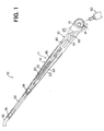
- Fig. 1 shows a backside of a wiper arm constituting a part of a windshield wiper device according to a first embodiment of the present invention.
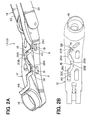
- Fig. 2A is a perspective view of a backside of an arm head as a part of the wiper arm of Fig. 1.
- Fig. 2B is a plane view of the arm head of Fig. 2A.
- a windshield wiper device 10 has a wiper arm 11 driven through a pivot shaft 50 by a power source such as wiper motor (not shown) and a wiper blade (not shown) to be attached to the wiper arm 11 for wiping a windshield glass (not shown). Since the power source, the wiper blade and the windshield glass are well known, the structures thereof are not be elaborated for the sake of brevity.
- the wiper arm 11 has an arm head 12, a retainer 14, and an arm piece 32.
- the retainer 14 and the arm piece 32 constitute an arm element.
- An end of the arm head 12 is fixed to the pivot shaft 50, which is rotatably attached to a vehicle body, so that the arm head 12 rotate always together with the pivot shaft 50.
- the arm head 12 is provided at an end on a backside thereof with a skirt 16 surrounding the pivot shaft 50 and at a center on a backside thereof with an elongated and undulated groove 18 extending longitudinally.
- Opposed side walls forming the groove 18 are waved to constitute hill portions (second, first and third hill portions) 20A, 20B and 20C and dale portions (second, first and third dale portions) 26A, 26B and 26C which face alternately each other so that the groove 18 is formed in an undulated shape.
- a part of a washer hose 46 is accommodated and held in the groove 18 along a longitudinal direction thereof.
- the other end of the arm head 12 is pivotally connected to an end of the retainer 14 via a holding pin (not shown) so that the retainer 14 rotates about an axis of the holding pin by a given angle in a direction coming near or away from the windshield glass.
- a tension coil spring 30, which is mainly positioned in a cavity of the one side opened square shaped retainer 14, is retained between the retainer 14 and the arm head 12 and urges always the retainer 14 toward the windshield glass.
- An end of the arm piece 32 is fixed to the other end of the retainer 14.
- the other end of the arm piece 32 is terminated in a U shaped hook (not shown), which interconnects the wiper blade via a clip (not shown).
- the retainer 14 and the arm piece 32 may be simultaneously manufactured and integrated into one body.
- Intermediate and leading end washer nozzles 34 and 36 are mounted on the wiper arm 11, respectively.
- the intermediate and leading end washer nozzles 34 and 36, which are held unrotatably by the retainer 14, are positioned between the sidewalls 22 inside the retainer 14 at longitudinally intermediate and leading end positions thereof, respectively.
- the intermediate washer nozzle 34 is connected to an end of the hose 46, whose the other end is connected via a washer pump (not shown) to a washer tank (not shown) mounted inside the hood of the vehicle body.
- the hose 46 is drawn out from the hood to outside through a hose aperture (not shown) of the vehicle body, which is provided in a vicinity of the pivot shaft 50, and, after being introduced to the backside of the arm head 12, inserted into the groove 18 so that the hose 46 is held in the groove 18. Then, the hose 46 extends toward the intermediate washer nozzle 34 in and along a cavity formed by the sidewalls 22 of the retainer 14 in such a manner that the hose 46 passes through a coil center hole of the spring 30.
- the intermediate washer nozzle 34 is connected to an end of an auxiliary hose 52, whose the other end is connected to the leading end washer nozzle 36.
- the washer liquid is delivered to the intermediate washer nozzle 34 via the hose 46 and to the leading end washer nozzle 36 via the auxiliary hose 52.
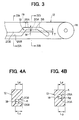
- Fig. 3 shows a schematic view of adjacent hill portions 20A and 20B forming the groove 18.
- a distance T perpendicular to a longitudinal direction (in a width direction) of the groove 18 between tops of the hill portions 20A and 20B, which are opposed to each other in the width direction of the groove 18 (in a width direction of the arm head 12) and adjacent to each other in a longitudinal direction of the groove 18 (in a longitudinal direction of the arm head), is shorter than a diameter ⁇ of the hose 46. Accordingly, even if a force acts on the hose 46 in the longitudinal direction of the groove 18 so that the hose 46 is pulled to deform in a straight line, the hose 46 comes in frictional engagement with peripheries of the tops of the hill portions 20A and 20B.
- the distance T is zero, more preferably, less than zero.
- the hose 46 to be held in the groove 18 is more undulated so that, when the hose 46 is pulled in the longitudinal direction of the groove 18, a friction between the hose 46 and the hill portions 20A and 20B is larger.
- the arm head 12 is provided with at least two of the hill portions, or, more preferably, two pairs of the hill and dale portions among the hill portions 20A, 20B and 20C and the dale portions 26A, 26B and 26C, it is effective to prevent the hose 46 from slipping out of the groove 18 in a longitudinal direction of the groove 18 when the force pulls the hose 46 in a longitudinal direction of the groove 18.
- each of the hill portions 20A and 20C is provided on an opening side of the groove 18 (at an upper surface thereof) with a projection 38 or 40 extending perpendicularly toward each of the dale portions 26A and 26C opposed thereto to overhang the groove so that a cross section of the groove 18 at this position is shaped a letter L.
- a length L D in a groove depth direction from a bottom of the groove 18 to an upper surface of the sidewall having the projection 38 or 40 is substantially equal to or, preferably, shorter than a length L E in a groove depth direction from the bottom of the groove 18 to an upper surface of the sidewall opposed to the projection 38 or 40.
- a length M (Width of the groove 18) between each free end of the projections 38 and 40 and each sidewall (the dale portion 26A or 26C) opposed to the projections 38 and 40 is smaller than the diameter of the hose 46.
- a width K of the groove 18 is larger than the diameter of the hose 46. In this case, since the hose 46, once having been inserted into the groove 18, is not pressed to deform by the opposed sidewalls unless the hose 46 is pulled in a longitudinal direction of the groove 18.
- the rotation of the pivot shaft 50 causes the reciprocal rotating movement of the wiper arm 11, so the wiper blade swings so as to remove the raindrops on the windshield glass.
- the washer liquid jets from the intermediate and leading end washer nozzles 34 and 36 can strike the windshield glass in the aimed positions to be wiped by the wiper blade, even if the wiping range of the wiper blade is widely spread.
- the width M of the groove 18 between each free end of the projections 38 and 40 and each sidewall (the dale portion 26A or 26C) opposed to the projections 38 and 40 is smaller than the diameter of the hose 46, the hose 46 is once deformed into an elongated shape when the force is inserted into the groove 18. However, the hose 46 is returned to an original shape due to its own elasticity after having been inserted into the groove 18 since the width K of the groove 18 is larger than the diameter of the hose 46 so that the hose 48 never slips out of the groove 18 and is firmly and stably held in the groove 18.
- the hose 46 comes in frictional contact with the top peripheries of the hill portion 20A, 20B and 20C since the groove 18 is formed substantially in a continuous wave shape by the hill portions 20A, 20B and 20C and dale portions 26A, 26B and 26C which face alternately each other. Accordingly, the hose 46 is prevented from slipping out of the groove 18 in a longitudinal direction of the groove 18. As the force to pull the hose 46 is larger, the frictional resistance between the hose 46 and the hill portions 20A, 20B and 20C is larger. Thus, the hose 43 is firmly and stably held in place in the groove 18 even if the hose 46 is pulled longitudinally by the force applied from outside or generated according to the rotation of the wiper arm 11.
- each of the projection 38 and 40 is provided at each of the hill portions 20A and 20C to form the groove 18 in a letter L shape, the projections 38 and 40 prevent the hose 46 inserted into the L shaped groove 18 from coming off the groove 18.
- the hose 46 is fitted deep into the L shaped groove 18 so that the hose 46 is more deeply held in the groove 18.
- the projection 38 or 40 is prone to be damaged, if directly hits the iced snow stack X, since the thickness of the projection 38 or 40 in a groove depth direction is relatively thin. Accordingly, it is preferable that the length L D is shorter than the length L E to avoid the direct collision of the projection 38 or 40 with the iced snow stack.
- the projection 38 or 40 may be provided at a periphery thereof with a chamfering portion 42.
- the chamfering portion 42 prevents the iced snow stack from scratching the projection 38 or 40 so that the projection 38 or 40 is hardly damaged.
- the width K of the groove 18 may be smaller than the diameter of the hose 46.
- the hose 46 which has been inserted into the groove 18, is elastically deformed to elongate in a depth direction of the groove 18 so that the hose 46 is sandwiched between and held firmly by the opposed sidewalls of the grooves 18. This will serve to hold the hose 46 in space in the groove 18 even without providing the projection 38 or 40.
- the hose 46 is held in the groove 18 without using a conventional clip or clips as an extra part, which prevents the hose from sipping out of the groove, with less numbers of assembly steps.
- the arm head 12 is generally manufactured by injection molding in such a manner that molten metal or resin is injected into dies.
- the dies are separable into two pieces in opposite directions and parallel to an axial direction of a hole into which the pivot shaft 50 is inserted and fixed.
- the groove 18 just behind the projection 38 or 40 constitutes an undercut portion so that, to form the groove 18 just behind the projection 38 or 40, a slide die moving perpendicularly to a moving direction of the split dies is required.
- the windshield wiper device 10 has projections 38 and 40 protruding in a width direction of the groove 18 out of the hill portions 20A and 20C which are located only on one side of the sidewalls forming the groove 18. Accordingly, the slide die arranged only on one width side of the groove 18 is required so that the die apparatus is inexpensive and the arm head 12 keeps an attractive appearance since the holes 19 open only to the one width side of the groove 18, as shown in Fig. 2A.
- the apparatus is composed of a split die 60, which is composed of an upper die 60A and a lower die 60B, and a slide die 62.
- the split die 60 can be split into the upper die 60A and the lower die 60B which move generally in opposite depth directions of the groove 18.
- the upper and lower dies 60A and 60B in contact with each other is provided inside with a cavity 64 into which molten metal or material such as aluminum or resin is injected.
- the slide die 62 moves into and from the cavity 64 in a direction different from, preferably, perpendicularly to the moving direction of the split die 60 and, on sliding into the cavity 64 along the split die 60, forms the groove 18 just behind the projection 38 or 40.
- the slide die 62 is located outside one of the sidewalls forming the groove 18 and the thickness of the one of the sidewalls at the bottom of the dale portion 26A or 26C is thinner than the thickness of the other of the sidewalls at the bottom of the dale portion 26B. That is, the distance from an outer periphery of the sidewall of the arm head 12 to the bottom of the dale portion 26A or 26C is shorter than a distance from the outer periphery of the sidewall of the arm head 12 to the bottom of the dale portion 26B.
- the slide die 62 moves across the bottom of the dale portion 26A or 26C toward the top of the hill portion 20A or 20C having the projection 38 or 40 to form the groove 18 just behind the projection 38 or 40.
- a distance during which the slide die 62 moves inside the arm head 12 to form the groove 18 of the undercut portion is the shortest since the slide die 62 moves toward the bottom of the dale portion 26A or 26C opposed to the hill portion 20A or 20C. Accordingly, a moving stroke of the slide die 62 is shorter so that a time required for manufacturing the arm head 12 is shorter.
- the slide die 26 is located only on one side of the sidewalls of the arm head 12 and moves into the cavity 64 only from one side thereof, the apparatus of manufacturing the arm head is compact.
- the hole 19 is provided only on one side of the width direction of the arm head 12 so that the attractive appearance of the arm head 12 can be assured.
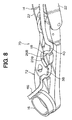
- Awindshieldwiper device 70 having an arm head 72 according to a second embodiment is described with reference to Figs. 7 to 10.
- the arm head 72 is provided on a backside thereof with an elongated and undulated groove 18 and projections 38 and 40, similarly to those of the arm head 12 according to the first embodiment.
- the hose 46 is inserted into and firmly held by the groove 18 even if there are no dale portions of one of the sidewall of the groove opposed to hill portions of the other of the sidewall thereof since the hose 46 comes in frictional engagement with the hill portions adjacent in a longitudinal direction of the groove and the projection 38 or 40 prevents the hose from slipping out of the groove 18 when the hose 46 is pulled in the longitudinal direction of the arm head 72 by the generated force.
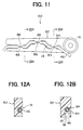
- Awindshieldwiper device 80 having an arm head 82 according to a third embodiment is described with reference to Figs. 11 to 13.
- the arm head 80 is provided with an elongated and undulated groove 18, similarly to that of the first embodiment.
- the arm head 80 is further provided with plural pairs of projections 84, 86 and 88 which are formed on tops of the hill portions 20A, 20B and 20C and on bottoms of the dale portions 26A, 26B and 26C, respectively.
- Each pair of projections 84, 86 or 88 extend in a width direction of the groove 18 to overhang the groove 18 and a gap M is formed between free end of the projections 84, 86 or 88.
- the gap M is narrower than the diameter of the hose 46.
- each length of the projections 84, 86 or 88 in a width direction of the groove 18 is shorter so that each strength of the projections 84, 86 or 88 is stronger, which is hardly damaged.
- the groove 18 just behind each pair of the projections 84, 86 or 88 can be formed by the slide die 62 sliding from one width side of the groove 18.
- An arm head (12) of a windshield wiper device (10) is provided on a backside thereof with an undulated groove (18) formed by side walls.
- the sidewalls have plural hill portions (20A, 20B, 20C) protruding in opposite directions alternately in a width direction of the arm head so as to be opposed to one another in a longitudinal direction thereof.
- Tops of the hill portions on one width side of the arm head are integrally provided at upper surfaces thereof with projections (38, 40) extending perpendicularly to a depth direction of the groove to overhang the groove.
- a hose (46) for delivering washer liquid to a washer nozzle (34, 36) is accommodated in the groove and firmly held by the hill portions and the projections without using an extra part such as a clip.
Landscapes
- Engineering & Computer Science (AREA)
- Mechanical Engineering (AREA)
- Body Structure For Vehicles (AREA)
- Connection Of Plates (AREA)
Abstract
Description
- The present invention relates to windshield wiper device mounting a washer nozzle and a washer hose, in particular, suitable for cleaning a windshield glass of a vehicle.
- Vehicle windshield wiper device for wiping a windshield glass has a wiper arm and a wiper blade attached to the wiper arm.
- The wiper arm has an arm head whose one end is fixed to a pivot shaft, a retainer whose one end is pivotally connected via a holding pin to the other end of the arm head to enable a given angle rotation about an axis of the pin, a spring retained between the arm head and the retainer for resiliently biasing the retainer toward the windshield glass, and an arm piece fixed to the other end of the retainer. An end of the arm piece terminates in a U shaped hook for connecting with the wiper blade. The wiper blade has a blade rubber for contacting and wiping the windshield glass and a plurality of levers holding the blade rubber.
- When the vehicle windshield wiper device is operated, the wiper arm and the wiper blade make well known reciprocating and rotating movements for removing raindrops on the windshield glass.
- Further, in a vehicle having a larger windshield glass in which a washer nozzle mounted on a hood of the vehicle is located relatively far from an aimed point of the windshield glass which washer liquid from the washer nozzle strikes, the washer nozzle is mounted on the wiper arm or wiper blade for delivering the washer liquid to the aimed point without fail, as shown in JP-U-61-97059 which discloses the windshield wiper device with a washer nozzle and the washer fluid hose that are attached to the wiper arm.
- According to the windshield wiper device proposed in JP-U-61-97059, a wiper head is provided on a backside thereof with a straight-line groove and a washer liquid hose is fitted in the groove. This structure has an advantage that the hose is properly routed through the groove and is out of sight from the user.
- However, the hose mounting structure mentioned above has a drawback that, if the hose is pulled longitudinally by a force applied from outside or generated according to the rotation of the wiper arm, the hose is prone to slip out of the groove since the hose is deformed to take the shortest route in a longitudinal direction of the wiper arm. Therefore, even if the groove is provided, a clip or clips as extra parts for holding the hose in place become necessary to prevent the hose from slipping out of the groove. The use of the extra parts and extra assembly steps thereof are costly.
- An object of the present invention is to provide a windshield wiper device in which a washer hose for delivering washer liquid to a washer nozzle amounted on a wiper arm or a wiper blade is firmly held by an arm head without using the extra parts and with less numbers of assembly steps.
- Another object of the present invention is to provide an apparatus of manufacturing the arm head for firmly holding the hose with less operating time and manufacturing cost.
- To achieve the former object mentioned above, the windshield wiper device has a pivot shaft, a wiper arm, a wiper blade, a washer nozzle and a washer hose. The wiper arm has an arm head whose one end is fixed to the pivot shaft to rotate about an axis of the pivot shaft, a retainer whose one end is pivotally connected via a holding pin to the other end of the arm head to enable a given angle rotation about an axis of the pin, an arm piece whose one end is fixed to the other end of the retainer and whose the other end is pivotally connected with the wiper blade. The wiper hose is arranged along the arm head and the retainer for connecting with the washer nozzle to deliver washer liquid thereto.
- With the arm head mentioned above, the arm head is provided with an undulated groove defined by groove sidewalls having at least first and second hill portions that protrude opposite to each other in a width direction of the arm head and are located adjacent to each other in a longitudinal direction thereof. A length between tops of the first and second hill portions in the width direction of the arm head is shorter than a diameter of the hose, or, preferably, is less than zero.
- The hose accommodated in the groove comes in frictional engagement with peripheries of the tops of the first and second hill portions when a force pulls the hose in a longitudinal direction of the arm head. Accordingly, this groove shape is effective to prevent the hose from slipping out of the groove in a longitudinal direction of the arm head. Further, as the force to pull the hose is larger, the frictional resistance between the hose and the hill portions is larger so that the hose is firmly held in the groove.
- It is preferable that the groove sidewalls further have a first dale portion that are opposed to the first hill portion in the width direction of the arm head and continuously adjacent to the second hill portion in the longitudinal direction thereof.
- It is more preferable that the groove side walls further have a third hill portion protruding oppositely to the first hill portion in a width direction of the arm head and being located continuously adjacent to the first dale portion on a side opposite to the second hill portion in the longitudinal direction thereof.
- Preferably, at least one of the tops of the first, second and third hill portions, preferably, each of the tops of the second and third hill portions, is provided at an upper surface thereof with a projection protruding in the width direction of the arm head so as to overhang the groove. The projection or projections prevent the hose inserted into the groove from coming off the groove. In particular, when a force acts on the hose in a longitudinal direction of the groove, the hose is fitted deep into the groove so that the hose is more deeply held in the groove.
- The arm head is generally manufactured by in jectionmolding in such a manner that molten metal or resin is injected into split die. The split die is separable into two pieces in opposite directions and parallel to an axial direction of a hole into which the pivot shaft is inserted and fixed. The groove just behind the projection constitutes an undercut portion so that, to form the groove just behind the projection, a slide die moving perpendicularly to a moving direction of the split die is required.
- It is preferable that the slide die is located on a side of a periphery of the arm head, a distance from which in the width direction thereof to one of the tops of the first and second hill portions is shorter than that to the other of the tops of the first and second hill portions. Accordingly, a moving stroke of the slide die is shorter so that a time required for manufacturing the arm head is shorter.
- Other features and advantages of the present invention will be appreciated, as well as methods of operation and the function of the related parts, from a study of the following detailed description, the appended claims, and the drawings, all of which form a part of this application. In the drawings:
- Fig. 1 is a backside view of a wiper arm constituting a part of a windshield wiper device according to a first embodiment of the present invention;
- Fig. 2A is a perspective backside view of an arm head as a part of the wiper arm of Fig. 1;
- Fig. 2B is a plane view of the arm head of Fig. 2A;
- Fig. 3 is a schematic view of groove sidewalls constituting a groove according to the first embodiment;
- Fig. 4A is a cross sectional view taken along a line IVA-IVA of Fig. 3;
- Fig. 4B is a cross sectional view taken along a line IVB-IVB of Fig. 3;
- Fig. 5 is a view showing a possibility that a projection according to the first embodiment may hit an iced snow stack;
- Fig. 6 is a cross sectional view of a modification of Fig. 4B;
- Fig. 7 is a cross sectional view of an apparatus of manufacturing the arm head according to the first embodiment;
- Fig. 8 is a backside view of an arm head according to a second embodiment of the present invention;
- Fig. 9 is a schematic view of groove sidewalls constituting a groove according to the second embodiment;
- Fig. 10A is a cross sectional view taken along a line XA- XA of Fig. 9;
- Fig. 10B is a cross sectional view taken along a line XB-XB of Fig. 9;
- Fig.11 is a backside view of an arm head according to a third embodiment of the present invention;
- Fig. 12A is a cross sectional view taken along a line XIIA-XIIA of Fig. 11; and
- Fig. 12B is a cross sectional view taken along a line XIIB-XIIB of Fig. 11;
-
- Preferred embodiments of the present invention are described with reference to figures attached hereto.
- Fig. 1 shows a backside of a wiper arm constituting a part of a windshield wiper device according to a first embodiment of the present invention. Fig. 2A is a perspective view of a backside of an arm head as a part of the wiper arm of Fig. 1. Fig. 2B is a plane view of the arm head of Fig. 2A.
- A
windshield wiper device 10 has awiper arm 11 driven through apivot shaft 50 by a power source such as wiper motor (not shown) and a wiper blade (not shown) to be attached to thewiper arm 11 for wiping a windshield glass (not shown). Since the power source, the wiper blade and the windshield glass are well known, the structures thereof are not be elaborated for the sake of brevity. - The
wiper arm 11 has anarm head 12, aretainer 14, and anarm piece 32. Theretainer 14 and thearm piece 32 constitute an arm element. An end of thearm head 12 is fixed to thepivot shaft 50, which is rotatably attached to a vehicle body, so that thearm head 12 rotate always together with thepivot shaft 50. As shown in Fig. 2, thearm head 12 is provided at an end on a backside thereof with askirt 16 surrounding thepivot shaft 50 and at a center on a backside thereof with an elongated and undulatedgroove 18 extending longitudinally. Opposed side walls forming thegroove 18 are waved to constitute hill portions (second, first and third hill portions) 20A, 20B and 20C and dale portions (second, first and third dale portions) 26A, 26B and 26C which face alternately each other so that thegroove 18 is formed in an undulated shape. A part of awasher hose 46 is accommodated and held in thegroove 18 along a longitudinal direction thereof. - The other end of the
arm head 12 is pivotally connected to an end of theretainer 14 via a holding pin (not shown) so that theretainer 14 rotates about an axis of the holding pin by a given angle in a direction coming near or away from the windshield glass. Theretainer 14, whose cross section is formed in one side opened square shape and whose backside is opened toward the windshield glass, has a pair ofsidewalls 22 and anupper wall 24. - A
tension coil spring 30, which is mainly positioned in a cavity of the one side opened square shapedretainer 14, is retained between theretainer 14 and thearm head 12 and urges always theretainer 14 toward the windshield glass. - An end of the
arm piece 32 is fixed to the other end of theretainer 14. The other end of thearm piece 32 is terminated in a U shaped hook (not shown), which interconnects the wiper blade via a clip (not shown). Theretainer 14 and thearm piece 32 may be simultaneously manufactured and integrated into one body. - Intermediate and leading
end washer nozzles wiper arm 11, respectively. The intermediate and leadingend washer nozzles retainer 14, are positioned between the sidewalls 22 inside theretainer 14 at longitudinally intermediate and leading end positions thereof, respectively. - The
intermediate washer nozzle 34 is connected to an end of thehose 46, whose the other end is connected via a washer pump (not shown) to a washer tank (not shown) mounted inside the hood of the vehicle body. Thehose 46 is drawn out from the hood to outside through a hose aperture (not shown) of the vehicle body, which is provided in a vicinity of thepivot shaft 50, and, after being introduced to the backside of thearm head 12, inserted into thegroove 18 so that thehose 46 is held in thegroove 18. Then, thehose 46 extends toward theintermediate washer nozzle 34 in and along a cavity formed by thesidewalls 22 of theretainer 14 in such a manner that thehose 46 passes through a coil center hole of thespring 30. Further, theintermediate washer nozzle 34 is connected to an end of an auxiliary hose 52, whose the other end is connected to the leadingend washer nozzle 36. Thus, the washer liquid is delivered to theintermediate washer nozzle 34 via thehose 46 and to the leadingend washer nozzle 36 via the auxiliary hose 52. - Fig. 3 shows a schematic view of
adjacent hill portions groove 18. - As shown in Fig. 3, a distance T perpendicular to a longitudinal direction (in a width direction) of the
groove 18 between tops of thehill portions hose 46. Accordingly, even if a force acts on thehose 46 in the longitudinal direction of thegroove 18 so that thehose 46 is pulled to deform in a straight line, thehose 46 comes in frictional engagement with peripheries of the tops of thehill portions - Preferably, the distance T is zero, more preferably, less than zero. As the tops of the
hill portions groove 18, thehose 46 to be held in thegroove 18 is more undulated so that, when thehose 46 is pulled in the longitudinal direction of thegroove 18, a friction between thehose 46 and thehill portions - As mentioned above, if the
arm head 12 is provided with at least two of the hill portions, or, more preferably, two pairs of the hill and dale portions among thehill portions dale portions hose 46 from slipping out of thegroove 18 in a longitudinal direction of thegroove 18 when the force pulls thehose 46 in a longitudinal direction of thegroove 18. - Further, as more clearly shown in Fig. 4B, each of the
hill portions projection dale portions groove 18 at this position is shaped a letter L. - Furthermore, as shown in Figs. 4A and 4B, a length LD in a groove depth direction from a bottom of the
groove 18 to an upper surface of the sidewall having theprojection groove 18 to an upper surface of the sidewall opposed to theprojection - Moreover, as shown in Figs. 2B and 3, a length M (Width of the groove 18) between each free end of the
projections dale portion projections hose 46. - Further, it is preferable, as shown in Figs. 4A and 4B, that a width K of the
groove 18 is larger than the diameter of thehose 46. In this case, since thehose 46, once having been inserted into thegroove 18, is not pressed to deform by the opposed sidewalls unless thehose 46 is pulled in a longitudinal direction of thegroove 18. - According to the
windshield wiper device 10 mentioned above, the rotation of thepivot shaft 50 causes the reciprocal rotating movement of thewiper arm 11, so the wiper blade swings so as to remove the raindrops on the windshield glass. - Since the intermediate and leading
end washer nozzles wiper arm 11, the washer liquid jets from the intermediate and leadingend washer nozzles - Further, since the width M of the
groove 18 between each free end of theprojections dale portion projections hose 46, thehose 46 is once deformed into an elongated shape when the force is inserted into thegroove 18. However, thehose 46 is returned to an original shape due to its own elasticity after having been inserted into thegroove 18 since the width K of thegroove 18 is larger than the diameter of thehose 46 so that the hose 48 never slips out of thegroove 18 and is firmly and stably held in thegroove 18. - Furthermore, when a force acts on the
hose 46 in the longitudinal direction of thegroove 18 so that thehose 46 is pulled to deform in a straight line, thehose 46 comes in frictional contact with the top peripheries of thehill portion groove 18 is formed substantially in a continuous wave shape by thehill portions dale portions hose 46 is prevented from slipping out of thegroove 18 in a longitudinal direction of thegroove 18. As the force to pull thehose 46 is larger, the frictional resistance between thehose 46 and thehill portions groove 18 even if thehose 46 is pulled longitudinally by the force applied from outside or generated according to the rotation of thewiper arm 11. - Moreover, since each of the
projection hill portions groove 18 in a letter L shape, theprojections hose 46 inserted into the L shapedgroove 18 from coming off thegroove 18. In particular, when a force acts on thehose 46 in a longitudinal direction of thegroove 18, thehose 46 is fitted deep into the L shapedgroove 18 so that thehose 46 is more deeply held in thegroove 18. - Further, as shown in Fig. 5, when the
arm head 12 hits an iced snow stack X between thearm head 12 and the windshield glass according to the swing movement of thewiper arm 11, theprojection projection projection - Furthermore, as shown in Fig. 6, the
projection chamfering portion 42. The chamferingportion 42 prevents the iced snow stack from scratching theprojection projection - Moreover, the width K of the
groove 18 may be smaller than the diameter of thehose 46. In this case, thehose 46, which has been inserted into thegroove 18, is elastically deformed to elongate in a depth direction of thegroove 18 so that thehose 46 is sandwiched between and held firmly by the opposed sidewalls of thegrooves 18. This will serve to hold thehose 46 in space in thegroove 18 even without providing theprojection - According to the windshield wiper device mentioned above, the
hose 46 is held in thegroove 18 without using a conventional clip or clips as an extra part, which prevents the hose from sipping out of the groove, with less numbers of assembly steps. - The
arm head 12 is generally manufactured by injection molding in such a manner that molten metal or resin is injected into dies. The dies are separable into two pieces in opposite directions and parallel to an axial direction of a hole into which thepivot shaft 50 is inserted and fixed. Thegroove 18 just behind theprojection groove 18 just behind theprojection projection hill portion 20B, another slide die moving in an opposite direction to the former slide die is necessary so that the die equipment is costly and thearm head 12 is obliged to haveholes 19, which are formed by the sliding movement of the slide dies, on opposite sides thereof, resulting in an unattractive appearance. - The
windshield wiper device 10 according to the first embodiment hasprojections groove 18 out of thehill portions groove 18. Accordingly, the slide die arranged only on one width side of thegroove 18 is required so that the die apparatus is inexpensive and thearm head 12 keeps an attractive appearance since theholes 19 open only to the one width side of thegroove 18, as shown in Fig. 2A. - An apparatus of manufacturing the
arm head 12 by injection molding is described below. - As shown in Fig. 7, the apparatus is composed of a split die 60, which is composed of an
upper die 60A and a lower die 60B, and aslide die 62. The split die 60 can be split into theupper die 60A and the lower die 60B which move generally in opposite depth directions of thegroove 18. The upper and lower dies 60A and 60B in contact with each other is provided inside with acavity 64 into which molten metal or material such as aluminum or resin is injected. - The slide die 62 moves into and from the
cavity 64 in a direction different from, preferably, perpendicularly to the moving direction of the split die 60 and, on sliding into thecavity 64 along the split die 60, forms thegroove 18 just behind theprojection - The slide die 62 is located outside one of the sidewalls forming the
groove 18 and the thickness of the one of the sidewalls at the bottom of thedale portion dale portion 26B. That is, the distance from an outer periphery of the sidewall of thearm head 12 to the bottom of thedale portion arm head 12 to the bottom of thedale portion 26B. The slide die 62 moves across the bottom of thedale portion hill portion projection groove 18 just behind theprojection - As mentioned above, a distance during which the slide die 62 moves inside the
arm head 12 to form thegroove 18 of the undercut portion, that is, an axial length of thehole 19, is the shortest since the slide die 62 moves toward the bottom of thedale portion hill portion arm head 12 is shorter. - As mentioned above, as the volume of the
hole 19 which is inevitably formed by the movement of the slide die 26 is limited to a smaller value, strength of thearm head 12 is scarcely reduced. - Further, since the slide die 26 is located only on one side of the sidewalls of the
arm head 12 and moves into thecavity 64 only from one side thereof, the apparatus of manufacturing the arm head is compact. - Moreover, the
hole 19 is provided only on one side of the width direction of thearm head 12 so that the attractive appearance of thearm head 12 can be assured. -
Awindshieldwiper device 70 having anarm head 72 according to a second embodiment is described with reference to Figs. 7 to 10. - The
arm head 72 is provided on a backside thereof with an elongated and undulatedgroove 18 andprojections arm head 12 according to the first embodiment. - A part of sidewalls constituting the
groove 18, which is a portion corresponding to thehill portion hill portion projection arm head 18 on one width side thereof, which is a side from which the slide die 62 is inserted, is thinner than that on the other width side thereof. Accordingly, there is no holes like theholes 19 in the first embodiment, each of which is formed to penetrate one of the side wall of thegroove 18 on inserting the slide die 62 into the split die 62 and thecavity 64 to form thegroove 18 just behind theprojection - In the
arm head 72, thehose 46 is inserted into and firmly held by thegroove 18 even if there are no dale portions of one of the sidewall of the groove opposed to hill portions of the other of the sidewall thereof since thehose 46 comes in frictional engagement with the hill portions adjacent in a longitudinal direction of the groove and theprojection groove 18 when thehose 46 is pulled in the longitudinal direction of thearm head 72 by the generated force. -
Awindshieldwiper device 80 having anarm head 82 according to a third embodiment is described with reference to Figs. 11 to 13. - The
arm head 80 is provided with an elongated and undulatedgroove 18, similarly to that of the first embodiment. Thearm head 80 is further provided with plural pairs ofprojections hill portions dale portions projections groove 18 to overhang thegroove 18 and a gap M is formed between free end of theprojections hose 46. - Since the pair of
projections groove 18, each length of theprojections groove 18 is shorter so that each strength of theprojections - Further, as shown in Fig. 12B, the
groove 18 just behind each pair of theprojections groove 18. - An arm head (12) of a windshield wiper device (10) is provided on a backside thereof with an undulated groove (18) formed by side walls. The sidewalls have plural hill portions (20A, 20B, 20C) protruding in opposite directions alternately in a width direction of the arm head so as to be opposed to one another in a longitudinal direction thereof. Tops of the hill portions on one width side of the arm head are integrally provided at upper surfaces thereof with projections (38, 40) extending perpendicularly to a depth direction of the groove to overhang the groove. A hose (46) for delivering washer liquid to a washer nozzle (34, 36) is accommodated in the groove and firmly held by the hill portions and the projections without using an extra part such as a clip.
Claims (18)
- Awindshield wiper device for wiping a windshield grass with a wiper blade via a wiper arm (11) to be driven by a pivot shaft (50) and a washer nozzle (34, 36) attached on at least one of the wiper blade and the wiper arm, the wiper arm comprising:wherein a length (T) between tops of the first and second hill portions in the width direction of the arm head is shorter than a diameter () of the hose and the hose is accommodated in and held by the groove.an arm head (12, 72, 82) whose one end is fixed to the pivot shaft to rotate about an axis of the pivot shaft, the arm head being provided with an undulated groove (18) defined by groove sidewalls having at least first and second hill portions (20B, 20A) that protrude opposite to each other in a width direction of the arm head and are located adjacent to each other in a longitudinal direction thereof;an arm element (14, 32) whose one end is pivotally connected to the other end of the arm and whose the other end is pivotally connected with the wiper blade; anda hose (46) arranged along the arm head and the arm element for connecting with the washer nozzle to deliver washer liquid thereto,
- Awindshield wiper device according to claim 1, wherein the groove sidewalls further have a first dale portion (26B) that is opposed to the first hill portion in the width direction of the arm head and continuously adjacent to the second hill portion in the longitudinal direction thereof.
- A windshield wiper device according to claim 2, wherein the hose elastically deforms and a width length (K) of the groove between the first hill and dale portions is shorter than the diameter of the hose.
- A windshield wiper device according to any one of claims 1 to 3, wherein the length (T) between tops of the first and second hill portions in the width direction of the arm head is less than zero.
- Awindshield wiper device according to any one of claims 2 to 4, wherein at least one of the tops of the first and second hill portions is provided at an upper surface thereof with a projection (38, 40) protruding in the width direction of the arm head so as to overhang the groove.
- Awindshieldwiper device according to claim 5, wherein a height (LD) from an upper surface of the projection to a surface of the groove opposed to the projection in a thickness direction of the arm head is shorter than a height (LE) in a thickness direction of the arm head of the other one of the first and second hill portions that is not provided with the projection.
- A windshield wiper device according to claim 5 or 6, wherein a distance from the one of the tops of the first and second hill portions having the projection to a periphery of the arm head in a width direction thereof is shorter than that from the other one of the tops of the first and second hill portions not having the projection to another periphery of the arm head in a width direction thereof.
- Awindshieldwiper device according to any one of claims 1 to 7, wherein the groove is provided on a backside of the arm head.
- Awindshieldwiper device according to any one of claims 5 to 7, wherein the projection is provided in the top of the first hill portion and a length (M) between a free end of the projection and a bottom of the first dale portion in a width direction of the arm head is shorter than the diameter of the hose.
- A windshield wiper device according to claim 9, wherein the arm head is provided with a through-hole (19) opened from the groove just behind the projection to a periphery of the first dale portion in a width direction of the arm head.
- A windshield wiper device according to claim 10, wherein the through-hole extends substantially perpendicularly to an axis of the pivot shaft.
- A windshield wiper device according to any one of claims 9 to 11, wherein a width (K) of the groove just behind the projection is longer than the diameter of the hose.
- A windshield wiper device according to claim 2, wherein the groove side walls further have a third hill portion (20C) protruding oppositely to the first hill portion in a width direction of the arm head and being located continuously adjacent to the first dale portion on a side opposite to the second hill portion in the longitudinal direction thereof.
- A windshield wiper device according to claim 13, wherein each top of the second and third hill portions is provided at an upper surface thereof with a projection (38, 40) protruding in the width direction of the arm head so as to overhang the groove.
- A windshield wiper device according to claim 13, wherein the groove sidewalls further have a second and third dale portions that are opposed to the second and third hill portions in the width direction of the arm head, respectively, and continuously adjacent to the first hill portion on opposite sides in the longitudinal direction thereof, respectively.
- A windshield wiper device according to claim 15, wherein at least one of a pair of the top of the first hill portion and a bottom of the first dale portion, a pair of the top of the second hill portion and a bottom of the second dale portion and a pair of the top of the third hill portion and a bottom of the third dale portion are provided at upper surfaces thereof with projections protruding opposite to each other in the width direction of the arm head so as to overhang the groove.
- An apparatus of manufacturing the arm head of the windshield wiper device according to claim 5, comprising:upper and lower dies (60A, 60B) movable in opposite directions and parallel to an axial direction of the pivot shaft, the upper and lower dies in contact with each other being provided inside with a cavity (64) into which molten material is injected for forming a body of the arm head; anda slide die (62) movable substantially perpendicularly to moving directions of the upper and lower dies, the slide die being partly inserted into the cavity for forming the groove just behind the projection before the molten material is injected.
- An apparatus of manufacturing the arm head according to claim 17, wherein the slide die is located on a side of a periphery of the arm head, a distance from which in the width direction thereof to one of the tops of the first and second hill portions is shorter than that to the other of the tops of the first and second hill portions.
Applications Claiming Priority (4)
| Application Number | Priority Date | Filing Date | Title |
|---|---|---|---|
| JP2001085954 | 2001-03-23 | ||
| JP2001085954A JP3717416B2 (en) | 2001-03-23 | 2001-03-23 | Wiper device |
| JP2001106260A JP3914716B2 (en) | 2001-04-04 | 2001-04-04 | Wiper apparatus and arm head manufacturing apparatus |
| JP2001106260 | 2001-04-04 |
Publications (3)
| Publication Number | Publication Date |
|---|---|
| EP1243488A2 true EP1243488A2 (en) | 2002-09-25 |
| EP1243488A3 EP1243488A3 (en) | 2004-12-15 |
| EP1243488B1 EP1243488B1 (en) | 2006-12-20 |
Family
ID=26611957
Family Applications (1)
| Application Number | Title | Priority Date | Filing Date |
|---|---|---|---|
| EP02005912A Expired - Lifetime EP1243488B1 (en) | 2001-03-23 | 2002-03-14 | Windshield wiper device mounting washer nozzle and hose |
Country Status (3)
| Country | Link |
|---|---|
| US (1) | US6804854B2 (en) |
| EP (1) | EP1243488B1 (en) |
| DE (1) | DE60216836T2 (en) |
Cited By (5)
| Publication number | Priority date | Publication date | Assignee | Title |
|---|---|---|---|---|
| EP1550592A3 (en) * | 2003-12-29 | 2005-12-14 | Robert Bosch Gmbh | Wiper arm, articulated arm for a wiper and method for producing a wiper arm |
| FR2991263A1 (en) * | 2012-05-29 | 2013-12-06 | Valeo Systemes Dessuyage | Trainer for brush-holder of wiper system for windscreen of car, has portion attached to another portion, where portions define cavity intended to receive washing liquid transport device for transporting washing liquid to windscreen |
| FR2993525A1 (en) * | 2012-07-19 | 2014-01-24 | Peugeot Citroen Automobiles Sa | Arm for windscreen wiper of e.g. car, has peripheral part comprising open semi-annular housing extending open housing in order to place portion of part of pipe, and holding leg projecting towards inner for axial maintenance of part |
| EP2740638A1 (en) * | 2012-12-10 | 2014-06-11 | Valeo Systèmes D'Essuyage | Driving system, device for supporting a pipe, in particular of washer liquid, and corresponding wiping system |
| WO2020239222A1 (en) * | 2019-05-29 | 2020-12-03 | Trico Belgium S.a. | Windscreen wiper arm |
Families Citing this family (9)
| Publication number | Priority date | Publication date | Assignee | Title |
|---|---|---|---|---|
| US20070018012A1 (en) * | 2005-07-19 | 2007-01-25 | Harris Daryl G | Nozzle and method of making the same |
| FR2967955B1 (en) * | 2010-11-29 | 2012-12-14 | Peugeot Citroen Automobiles Sa | CIRCUIT FOR DISPENSING WINDSCREEN LIQUID FOR MOTOR VEHICLE. |
| FR2993224B1 (en) * | 2012-07-12 | 2015-09-04 | Valeo Systemes Dessuyage | DEVICE FOR MAINTAINING A PIPE, IN PARTICULAR A WASHER FLUID |
| DE102014201211A1 (en) * | 2014-01-23 | 2015-07-23 | Robert Bosch Gmbh | wiper device |
| US9932017B2 (en) | 2014-11-05 | 2018-04-03 | Asmo Co., Ltd. | Vehicle wiper |
| WO2016167090A1 (en) * | 2015-04-17 | 2016-10-20 | 株式会社ミツバ | Wiper device |
| DE102015114933A1 (en) * | 2015-09-07 | 2017-03-09 | Firma Valeo Systèmes d'Essuyage | Wiper arm head for a wiper arm and wiper arm for vehicle windows |
| DE102019208809A1 (en) | 2019-06-18 | 2020-12-24 | Robert Bosch Gmbh | Wiper arm device, wiper arm and windshield wiper system |
| FR3157843A1 (en) * | 2024-05-15 | 2025-07-04 | Valeo Systèmes D’Essuyage | Actuating arm and wiping device |
Citations (1)
| Publication number | Priority date | Publication date | Assignee | Title |
|---|---|---|---|---|
| JPS6197059A (en) | 1984-10-19 | 1986-05-15 | Hitachi Koki Co Ltd | Continuous centrifugal separation rotor |
Family Cites Families (12)
| Publication number | Priority date | Publication date | Assignee | Title |
|---|---|---|---|---|
| US3916473A (en) * | 1974-02-25 | 1975-11-04 | H A S Investments Inc Entire | Wiper for windshields |
| JPS6197059U (en) | 1984-12-03 | 1986-06-21 | ||
| JPH0248251A (en) * | 1988-08-11 | 1990-02-19 | Nissan Motor Co Ltd | Wiper device |
| DE3907968A1 (en) * | 1989-03-11 | 1990-09-13 | Swf Auto Electric Gmbh | WINDOW CLEANING SYSTEM |
| DE4117106C2 (en) * | 1991-05-25 | 2000-03-09 | Teves Gmbh Alfred | Wiper arm, in particular for motor vehicles |
| DE4130023A1 (en) * | 1991-09-10 | 1993-03-11 | Swf Auto Electric Gmbh | Wiper arm for vehicle windscreen - has holding clasp for insertion of screen washer fluid delivery pipe |
| DE4134980B4 (en) * | 1991-10-23 | 2005-12-22 | Itt Automotive Europe Gmbh | Wiper device for windows of motor vehicles |
| FR2696394B1 (en) * | 1992-10-02 | 1994-12-02 | Journee Paul Sa | Wiper arm for wiping a headlight window of a motor vehicle comprising means for spraying the window with washing liquid. |
| FR2721886B1 (en) * | 1994-06-30 | 1996-08-02 | Valeo Systemes Dessuyage | WIPER ARM COMPRISING A DEVICE FOR SPRAYING THE WINDOW |
| WO1996018529A1 (en) * | 1994-12-16 | 1996-06-20 | United Technologies Automotive Systems, Inc. | Windshield wiper arm assembly |
| ES2179244T3 (en) * | 1996-07-04 | 2003-01-16 | Valeo Auto Electric Gmbh | WINDSHIELD WIPER ARM OF A WINDSHIELD DEVICE FOR VEHICLE MOONS. |
| US6094772A (en) | 1998-01-30 | 2000-08-01 | Itt Manufacturing Enterprises, Inc. | Windshield wiper arm retainer with integral nozzle bracket |
-
2002
- 2002-03-12 US US10/095,076 patent/US6804854B2/en not_active Expired - Lifetime
- 2002-03-14 EP EP02005912A patent/EP1243488B1/en not_active Expired - Lifetime
- 2002-03-14 DE DE60216836T patent/DE60216836T2/en not_active Expired - Lifetime
Patent Citations (1)
| Publication number | Priority date | Publication date | Assignee | Title |
|---|---|---|---|---|
| JPS6197059A (en) | 1984-10-19 | 1986-05-15 | Hitachi Koki Co Ltd | Continuous centrifugal separation rotor |
Cited By (6)
| Publication number | Priority date | Publication date | Assignee | Title |
|---|---|---|---|---|
| EP1550592A3 (en) * | 2003-12-29 | 2005-12-14 | Robert Bosch Gmbh | Wiper arm, articulated arm for a wiper and method for producing a wiper arm |
| FR2991263A1 (en) * | 2012-05-29 | 2013-12-06 | Valeo Systemes Dessuyage | Trainer for brush-holder of wiper system for windscreen of car, has portion attached to another portion, where portions define cavity intended to receive washing liquid transport device for transporting washing liquid to windscreen |
| FR2993525A1 (en) * | 2012-07-19 | 2014-01-24 | Peugeot Citroen Automobiles Sa | Arm for windscreen wiper of e.g. car, has peripheral part comprising open semi-annular housing extending open housing in order to place portion of part of pipe, and holding leg projecting towards inner for axial maintenance of part |
| EP2740638A1 (en) * | 2012-12-10 | 2014-06-11 | Valeo Systèmes D'Essuyage | Driving system, device for supporting a pipe, in particular of washer liquid, and corresponding wiping system |
| FR2999130A1 (en) * | 2012-12-10 | 2014-06-13 | Valeo Systemes Dessuyage | TRAINER, DEVICE FOR MAINTAINING A PIPE, ESPECIALLY A WASHER LIQUID, AND A CORRESPONDING WIPING SYSTEM |
| WO2020239222A1 (en) * | 2019-05-29 | 2020-12-03 | Trico Belgium S.a. | Windscreen wiper arm |
Also Published As
| Publication number | Publication date |
|---|---|
| DE60216836D1 (en) | 2007-02-01 |
| EP1243488A3 (en) | 2004-12-15 |
| DE60216836T2 (en) | 2007-08-09 |
| US6804854B2 (en) | 2004-10-19 |
| EP1243488B1 (en) | 2006-12-20 |
| US20020133893A1 (en) | 2002-09-26 |
Similar Documents
| Publication | Publication Date | Title |
|---|---|---|
| EP1243488B1 (en) | Windshield wiper device mounting washer nozzle and hose | |
| JP4580124B2 (en) | Wiper arm | |
| US8959700B2 (en) | Wiper blade | |
| JP5584012B2 (en) | Wiper blade | |
| WO2015178319A1 (en) | Washer nozzle, wiper arm with nozzle, and vehicular wiper device | |
| CN104417498A (en) | Flat Wiper Blade and Coupling Method Thereof | |
| JP2007504995A (en) | Windshield wiper arm | |
| EP1733940B1 (en) | Vehicle wiper apparatus | |
| JP4970927B2 (en) | Wiper blade and vehicle wiper | |
| JP2015217842A (en) | Wiper arm with nozzle and wiper device for vehicle | |
| JP2002302019A (en) | Wiper arm | |
| KR100582857B1 (en) | Method for manufacturing wind swabs for wiper blades and wiper blades | |
| EP0731009B1 (en) | Windscreen wiper for a motor vehicle having a wiper arm equiped with a lifting device formed on the arm | |
| JP3717416B2 (en) | Wiper device | |
| JP6413349B2 (en) | Washer nozzle and vehicle wiper device | |
| US5768739A (en) | Connector member of windshield wiper | |
| US9731687B2 (en) | Wiper apparatus having integrally formed washer nozzle | |
| EP3517375A1 (en) | Wiper system including washer fluid spray member | |
| JP6228842B2 (en) | Wiper blade and wiper device for vehicle | |
| JP7321109B2 (en) | wiper arm | |
| KR0112400Y1 (en) | A device of wiper for a vehicle | |
| EP3024706B1 (en) | Windscreen wiper device | |
| JP2021049899A (en) | Wiper arm | |
| JP3992902B2 (en) | Manufacturing method of blade rubber | |
| KR102310968B1 (en) | Jet nozzle device for washer liquid installed at wiper arm tip |
Legal Events
| Date | Code | Title | Description |
|---|---|---|---|
| PUAI | Public reference made under article 153(3) epc to a published international application that has entered the european phase |
Free format text: ORIGINAL CODE: 0009012 |
|
| AK | Designated contracting states |
Kind code of ref document: A2 Designated state(s): AT BE CH CY DE DK ES FI FR GB GR IE IT LI LU MC NL PT SE TR |
|
| AX | Request for extension of the european patent |
Free format text: AL;LT;LV;MK;RO;SI |
|
| PUAL | Search report despatched |
Free format text: ORIGINAL CODE: 0009013 |
|
| AK | Designated contracting states |
Kind code of ref document: A3 Designated state(s): AT BE CH CY DE DK ES FI FR GB GR IE IT LI LU MC NL PT SE TR |
|
| AX | Request for extension of the european patent |
Extension state: AL LT LV MK RO SI |
|
| 17P | Request for examination filed |
Effective date: 20050228 |
|
| 17Q | First examination report despatched |
Effective date: 20050613 |
|
| AKX | Designation fees paid |
Designated state(s): DE GB IT |
|
| GRAP | Despatch of communication of intention to grant a patent |
Free format text: ORIGINAL CODE: EPIDOSNIGR1 |
|
| GRAS | Grant fee paid |
Free format text: ORIGINAL CODE: EPIDOSNIGR3 |
|
| GRAA | (expected) grant |
Free format text: ORIGINAL CODE: 0009210 |
|
| AK | Designated contracting states |
Kind code of ref document: B1 Designated state(s): DE GB IT |
|
| REG | Reference to a national code |
Ref country code: GB Ref legal event code: FG4D |
|
| REF | Corresponds to: |
Ref document number: 60216836 Country of ref document: DE Date of ref document: 20070201 Kind code of ref document: P |
|
| PLBE | No opposition filed within time limit |
Free format text: ORIGINAL CODE: 0009261 |
|
| STAA | Information on the status of an ep patent application or granted ep patent |
Free format text: STATUS: NO OPPOSITION FILED WITHIN TIME LIMIT |
|
| 26N | No opposition filed |
Effective date: 20070921 |
|
| REG | Reference to a national code |
Ref country code: GB Ref legal event code: 732E Free format text: REGISTERED BETWEEN 20181105 AND 20181107 |
|
| REG | Reference to a national code |
Ref country code: DE Ref legal event code: R082 Ref document number: 60216836 Country of ref document: DE Representative=s name: TBK, DE Ref country code: DE Ref legal event code: R081 Ref document number: 60216836 Country of ref document: DE Owner name: NIPPON WIPER BLADE CO.,LTD., KAZO-SHI, JP Free format text: FORMER OWNERS: ASMO CO., LTD., KOSAI-SHI, SHIZUOKA-KEN, JP; NIPPON WIPER BLADE CO.,LTD., KAZO-SHI, SAITAMA 347-8585, JP Ref country code: DE Ref legal event code: R081 Ref document number: 60216836 Country of ref document: DE Owner name: DENSO CORPORATION, KARIYA-CITY, JP Free format text: FORMER OWNERS: ASMO CO., LTD., KOSAI-SHI, SHIZUOKA-KEN, JP; NIPPON WIPER BLADE CO.,LTD., KAZO-SHI, SAITAMA 347-8585, JP Ref country code: DE Ref legal event code: R081 Ref document number: 60216836 Country of ref document: DE Owner name: DENSO WIPER SYSTEMS, INC., JP Free format text: FORMER OWNERS: ASMO CO., LTD., KOSAI-SHI, SHIZUOKA-KEN, JP; NIPPON WIPER BLADE CO.,LTD., KAZO-SHI, SAITAMA 347-8585, JP |
|
| REG | Reference to a national code |
Ref country code: DE Ref legal event code: R082 Ref document number: 60216836 Country of ref document: DE Representative=s name: TBK, DE Ref country code: DE Ref legal event code: R081 Ref document number: 60216836 Country of ref document: DE Owner name: DENSO WIPER SYSTEMS, INC., JP Free format text: FORMER OWNERS: DENSO CORPORATION, KARIYA-CITY, AICHI-PREF., JP; NIPPON WIPER BLADE CO.,LTD., KAZO-SHI, SAITAMA 347-8585, JP Ref country code: DE Ref legal event code: R081 Ref document number: 60216836 Country of ref document: DE Owner name: DENSO CORPORATION, KARIYA-CITY, JP Free format text: FORMER OWNERS: DENSO CORPORATION, KARIYA-CITY, AICHI-PREF., JP; NIPPON WIPER BLADE CO.,LTD., KAZO-SHI, SAITAMA 347-8585, JP |
|
| PGFP | Annual fee paid to national office [announced via postgrant information from national office to epo] |
Ref country code: IT Payment date: 20210329 Year of fee payment: 20 |
|
| PGFP | Annual fee paid to national office [announced via postgrant information from national office to epo] |
Ref country code: GB Payment date: 20210324 Year of fee payment: 20 Ref country code: DE Payment date: 20210319 Year of fee payment: 20 |
|
| REG | Reference to a national code |
Ref country code: DE Ref legal event code: R071 Ref document number: 60216836 Country of ref document: DE |
|
| REG | Reference to a national code |
Ref country code: GB Ref legal event code: PE20 Expiry date: 20220313 |
|
| PG25 | Lapsed in a contracting state [announced via postgrant information from national office to epo] |
Ref country code: GB Free format text: LAPSE BECAUSE OF EXPIRATION OF PROTECTION Effective date: 20220313 |