EP1243478A1 - Occupant restraint system and method for operating the same - Google Patents
Occupant restraint system and method for operating the same Download PDFInfo
- Publication number
- EP1243478A1 EP1243478A1 EP02250905A EP02250905A EP1243478A1 EP 1243478 A1 EP1243478 A1 EP 1243478A1 EP 02250905 A EP02250905 A EP 02250905A EP 02250905 A EP02250905 A EP 02250905A EP 1243478 A1 EP1243478 A1 EP 1243478A1
- Authority
- EP
- European Patent Office
- Prior art keywords
- impact
- occupant restraint
- stage
- restraint device
- vehicle
- Prior art date
- Legal status (The legal status is an assumption and is not a legal conclusion. Google has not performed a legal analysis and makes no representation as to the accuracy of the status listed.)
- Granted
Links
- 238000000034 method Methods 0.000 title claims abstract description 73
- 230000007704 transition Effects 0.000 claims abstract description 76
- 230000008569 process Effects 0.000 claims abstract description 60
- 230000001953 sensory effect Effects 0.000 claims abstract description 26
- 230000000452 restraining effect Effects 0.000 claims description 12
- 230000002411 adverse Effects 0.000 abstract description 5
- 230000000694 effects Effects 0.000 abstract description 3
- 230000001133 acceleration Effects 0.000 description 13
- 238000004891 communication Methods 0.000 description 9
- 230000002596 correlated effect Effects 0.000 description 3
- 238000005516 engineering process Methods 0.000 description 2
- 238000012986 modification Methods 0.000 description 2
- 230000004048 modification Effects 0.000 description 2
- 230000002035 prolonged effect Effects 0.000 description 2
- 230000004044 response Effects 0.000 description 2
- 230000007306 turnover Effects 0.000 description 2
- 230000005540 biological transmission Effects 0.000 description 1
- 238000012790 confirmation Methods 0.000 description 1
- 238000010586 diagram Methods 0.000 description 1
- 230000002427 irreversible effect Effects 0.000 description 1
Images




Classifications
-
- B—PERFORMING OPERATIONS; TRANSPORTING
- B60—VEHICLES IN GENERAL
- B60R—VEHICLES, VEHICLE FITTINGS, OR VEHICLE PARTS, NOT OTHERWISE PROVIDED FOR
- B60R21/00—Arrangements or fittings on vehicles for protecting or preventing injuries to occupants or pedestrians in case of accidents or other traffic risks
- B60R21/01—Electrical circuits for triggering passive safety arrangements, e.g. airbags, safety belt tighteners, in case of vehicle accidents or impending vehicle accidents
- B60R21/013—Electrical circuits for triggering passive safety arrangements, e.g. airbags, safety belt tighteners, in case of vehicle accidents or impending vehicle accidents including means for detecting collisions, impending collisions or roll-over
-
- B—PERFORMING OPERATIONS; TRANSPORTING
- B60—VEHICLES IN GENERAL
- B60R—VEHICLES, VEHICLE FITTINGS, OR VEHICLE PARTS, NOT OTHERWISE PROVIDED FOR
- B60R21/00—Arrangements or fittings on vehicles for protecting or preventing injuries to occupants or pedestrians in case of accidents or other traffic risks
- B60R21/01—Electrical circuits for triggering passive safety arrangements, e.g. airbags, safety belt tighteners, in case of vehicle accidents or impending vehicle accidents
- B60R2021/0104—Communication circuits for data transmission
-
- B—PERFORMING OPERATIONS; TRANSPORTING
- B60—VEHICLES IN GENERAL
- B60R—VEHICLES, VEHICLE FITTINGS, OR VEHICLE PARTS, NOT OTHERWISE PROVIDED FOR
- B60R21/00—Arrangements or fittings on vehicles for protecting or preventing injuries to occupants or pedestrians in case of accidents or other traffic risks
- B60R21/01—Electrical circuits for triggering passive safety arrangements, e.g. airbags, safety belt tighteners, in case of vehicle accidents or impending vehicle accidents
- B60R2021/0104—Communication circuits for data transmission
- B60R2021/01102—Transmission method
- B60R2021/01115—Transmission method specific data frames
Definitions
- the present invention relates to occupant restraint systems, such as an air bag and a pretensioner of a seat belt, mounted in a vehicle and, more particularly, an occupant restraint system and a method for operating the same for precluding an occupant restraint device from being improperly operated due to adverse effect caused by noises.
- an occupant restraint system of a vehicle It has been a usual practice for an occupant restraint system of a vehicle to have an impact detector section, which detects impact, and a control section which controls the actuation of an occupant restraint device, with the impact detector section and the control section being mechanically separate from one another and electrically connected to one another by means of a communication line.
- the impact detector section detects impact exerted to the vehicle and discriminates a need for operating the occupant restraint device
- the impact detector section transmits an actuation demand signal to the control section via the communication line.
- the control section Upon receipt of the actuation demand signal, the control section instantaneously deploys the occupant restraint device for thereby restraining the occupant in a safe condition.
- the technology disclosed in the above Publication is to produce communication signals at different number of output frequencies in an impact detector section while classifying a process, through which restraint judgment is implemented upon discriminating impact, into a plurality of stages which are allocated with particular output frequencies, respectively. Then, the impact detector section transmits output signals to the control section at the relevant frequencies associated with respective judgment stages. The control section executes discrimination for the frequencies of the received signals and deploys the occupant restraint device when the signals are received from the impact detector section in a predetermined sequence.
- the control section of the related art must receive the output signals from the impact detector section for a prolonged period of time in order to appropriately discriminate the output frequencies of the received signals from one another. To preclude the adverse affect caused by temporary variation in the output frequencies of the received signals containing noises, it is required for the control section to receive the signals from the impact detector section for a further prolonged period of time.
- the present invention has been made with a view to addressing the above issue and has an object of the present invention to provide an occupant restraint system and a method for operating the same which is able to preclude the system from being adversely affected with noises while enabling an occupant restraint device to be instantaneously deployed upon receipt of a restraint actuation signal from an impact detector unit.
- the present invention provides an occupant restraint system for a vehicle having an occupant restraint device to permit the occupant restraint device to be deployed for restraining the occupant in the vehicle when impact, exerted to the vehicle, is detected, said system comprising: an impact detector unit including an impact sensor detecting impact exerted to a vehicle to provide a sensory output representative of an impact status, said impact detector unit being responsive the impact status for providing at least two discriminating factors based on which at least two predetermined transition processes are programmed, to cause said occupant restraint device to be deployed, and producing information representing ON/OFF state of said discriminating factors involving transition process information representing said transition processes; and a control unit outputting an actuation signal to said occupant restraint device when a coincidence between a variation in said information, representing said ON/OFF state, received from said impact detector unit, and said transition process information involved in said information representing said ON/OFF state is confirmed.
- the present invention provides an occupant restraint system for a vehicle having an occupant restraint device to permit the occupant restraint device to be deployed for restraining the occupant in the vehicle when impact, exerted to the vehicle, is detected, said system comprising: an impact detector unit including at least two impact sensors detecting impact exerted to a vehicle to provide sensory outputs representative of impact status, said impact detector unit being responsive the impact status for providing at least two discriminating factors based on which at least two predetermined transition processes are programmed, to cause said occupant restraint device to be deployed, and producing information representing ON/OFF state of said discriminating factors involving transition process information representing said transition processes; and a control unit outputting an actuation signal to said occupant restraint device when a coincidence between a variation in said information representing said ON/OFF state, received from said impact detector unit, and said transition process information involved in said information representing said ON/OFF state is confirmed.
- an impact detector unit including at least two impact sensors detecting impact exerted to a vehicle to provide sensory outputs representative of
- the present invention provides an occupant restraint system for a vehicle having an occupant restraint device to permit the occupant restraint device to be deployed for restraining the occupant in the vehicle when impact, exerted to the vehicle, is detected, said system comprising: impact detecting means detecting impact exerted to a vehicle to provide a sensory output representative of an impact status, said impact detecting means being responsive the impact status for providing at least two discriminating factors based on which at least two predetermined transition processes are programmed, to cause said occupant restraint device to be deployed, and producing information representing ON/OFF state of said discriminating factors involving transition process information representing said transition processes; and control means outputting an actuation signal to said occupant restraint device when a coincidence between a variation in said information representing said ON/OFF state, received from impact detecting means, and said transition process information involved in said information representing said ON/OFF state is confirmed.
- the present invention provides an occupant restraint system for a vehicle having an occupant restraint device to permit the occupant restraint device to be deployed for restraining the occupant in the vehicle when impact, exerted to the vehicle, is detected, said system comprising: impact detecting means including at least two impact sensors detecting impact exerted to a vehicle to provide sensory outputs representative of impact status, said impact detecting means being responsive the impact status for providing at least two discriminating factors based on which at least two predetermined transition processes are programmed, to cause said occupant restraint device to be deployed, and producing information representing ON/OFF state of said discriminating factors involving transition process information representing said transition processes; and control means outputting an actuation signal to said occupant restraint device when a coincidence between a variation in said information representing said ON/OFF state, received from said impact detecting means, and said transition process information involved in said information representing said ON/OFF state is confirmed.
- impact detecting means including at least two impact sensors detecting impact exerted to a vehicle to provide sensory outputs representative of
- the present invention includes a method for operating an occupant restraint system for a vehicle having an occupant restraint device to permit the occupant restraint device to be deployed for restraining the occupant in the vehicle when impact, exerted to the vehicle, is detected, said method comprising: detecting impact exerted to a vehicle to provide a sensory output representative of an impact status; preparing at least two discriminating factors based on which at least two predetermined transition processes are settled to cause said occupant restraint device to be deployed; producing information representing ON/OFF state of said discriminating factors involving transition process information representing said transition processes; and outputting an actuation signal to said occupant restraint device when a coincidence between a variation in said information representing said ON/OFF state and said transition process information involved in said information representing said ON/OFF state is confirmed.
- the present invention includes a method for operating an occupant restraint system for a vehicle having an occupant restraint device to permit the occupant restraint device to be deployed for restraining the occupant in the vehicle when impact, exerted to the vehicle, is detected, said method comprising: detecting impact exerted to a vehicle using at least two impact sensors to provide sensory outputs representative of impact status; preparing at least two discriminating factors based on which at least two predetermined transition processes are programmed to cause said occupant restraint device to be deployed ; producing information representing ON/OFF state of said discriminating factors involving transition process information representing said transition processes; and outputting an actuation signal to said occupant restraint device when a coincidence between a variation in said information representing said ON/OFF state and said transition process information involved in said information representing said ON/OFF state is confirmed.
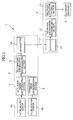
- FIG. 1 a representation of the present invention is schematically shown in FIG. 1 as an occupant restraint system, for a vehicle, of a preferred embodiment.
- the restraint system 1 includes a restraint device 2.
- the restraint device may be comprised of one of or any combination of devices.
- the restraint device 2 may be actuatable occupant restraint device that is mounted in the vehicle for restraining a vehicle occupant when the vehicle encounters an impact.
- Examples of such an occupant restraint device include an air bag device, a seat belt lock, and a seat belt pretensioner.
- the system 1 further includes an impact detector unit 3 which detects a front impact, a side impact, or rollover (turnover) as a characteristic that is used to determine whether a vehicle occupant is to be restrained, and a control unit 4 for applying an actuation signal to the restraint device 2 when impact is detected with the impact detector unit 3.
- the impact detector unit 3 and the control unit 4 are electrically connected through a communication line 5.
- the impact detector unit 3 is comprised of first and second acceleration sensors (impact sensors) 6a, 6b that detect impact exerted to the vehicle for producing first and second sensory outputs, respectively, in response thereto, an actuation timing discriminating section 7 responsive to the first sensory output for discriminating an actuation timing at which the occupant restraint device 2 is deployed, and an operational state discriminating section 8 responsive to the second sensory output for discriminating if a deployment impact condition is occurring for actuating the restraint device 2.
- the occupant restraint system 1 further includes a transmitting information discriminating section 9 which responds to outputs of the actuation timing discriminating section 7 and the operational state discriminating section 8 to discriminate variations in respective discriminating factors (involving an actuation demand timing judgment, a calculation start judgment, and an operative state judgment) for producing data representative of such discriminating factors, and a transmitter 10 which transmits data produced from the transmitting information discriminating section 9 to the control unit 4 via the communication line 5.
- a transmitting information discriminating section 9 which responds to outputs of the actuation timing discriminating section 7 and the operational state discriminating section 8 to discriminate variations in respective discriminating factors (involving an actuation demand timing judgment, a calculation start judgment, and an operative state judgment) for producing data representative of such discriminating factors
- a transmitter 10 which transmits data produced from the transmitting information discriminating section 9 to the control unit 4 via the communication line 5.
- the actuation timing discriminating section 7 serves to execute two functions, i.e. the actuation demand timing judgment and the calculation start judgment. Among these functions, the actuation demand timing judgment is turned ON when an integral result of the sensory output of the first acceleration sensor 6a exceeds a first threshold value. Further, the calculation start judgment is turned ON when the sensory output of the first acceleration sensor 6a exceeds a second threshold value.
- the operational state discriminating section 8 is turned ON when an integral result of the sensory output of the second acceleration sensor 6b exceeds a third threshold value.
- the first and third threshold values are exemplarily settled to be substantially identical to one another to cause the sample shown in FIG. 1 to operate in two modes, i.e. a first mode wherein the actuation demand timing judgment is first turned on owing to sensitive characteristic of the first and second acceleration sensors 6a, 6b, and a second mode wherein, on the contrary, the operational state judgment is first turned on.
- control unit 4 is comprised of a receiver 11 which receives data representative of the discriminating factors transmitted from the impact detector unit 3, a receiving information discriminating section 12 which is arranged to have a plurality of preliminarily programmed transition processes to be compared with relevant transition processes contained data, representative of the discriminating factors, received by the receiver 11 with a view to making determination as to whether the preliminarily programmed transition processes coincide with the transition processes preset in data representative of the discriminating factors for producing a coincidence signal when these parameters coincide with one another, and a restraint actuator control section 13 which outputs a trigger signal on the occupant restraint devices 2 in response to the coincidence signal delivered from the receiving information discriminating section.
- FIG. 2 shows a table illustrating the relationship among ON/OFF states of the respective discriminating factors (i.e. the actuation demand timing judgment, the calculation start judgment, and the operative state judgment), correlated transmitting data (involving DATA1 to DATA7) and associated stages (which will be discussed later in detail). It is to be noted that binary values "1" and "0" are assigned to an "ON” state and an "OFF" state of the discriminating factors, respectively.
- discriminating factors i.e. the actuation demand timing judgment, the calculation start judgment, and the operative state judgment
- correlated transmitting data involving DATA1 to DATA7
- associated stages which will be discussed later in detail
- DATA 0 is represented by three decimal numbers (0, 0, 0). Also, the three decimal numbers (0, 0, 0) represent the actuation demand timing judgment, the calculation start judgment and the operative state judgment, respectively, in sequence from the left.
- DATA 1 is represented by the three decimal numbers (0, 0, 1).
- DATA 2 is represented by the three decimal numbers (0, 1, 0)
- DATA 3 is represented by the three decimal numbers (0, 1, 1)
- DATA 4 is represented by the three decimal numbers (1, 1, 0)
- DATA 5 to DATA 7 are represented by the three decimal numbers (1,1,1).
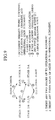
- the receiving information discriminating section 12 stores preliminarily programmed stages, representing the transition processes, such as NORMAL STAGE, STAGE 1-A, STAGE 1-B, STAGE 2-A, STAGE 2-B, and FINAL STAGE. Also stored in the receiving information discriminating section 12 are proper transition processes (including proper routes passing through the respective stages), such as a first path, a second path,and a third path.
- the first path represents a path wherein the transition process shifts through NORMAL STAGE, STAGE 1-A, STAGE 2-A, and FINAL STAGE in a sequence.
- the second path represents a path wherein the transition process shifts through NORMAL STAGE, STAGE 1-B, STAGE 2-A, and FINAL STAGE.
- the third path represents a path wherein the transition process shifts through NORMAL STAGE, STAGE 1-B, STAGE 2-B, and FINAL STAGE.
- the transition occurs among the various stages in a manner as shown in FIG. 9.
- three patterns of DATA 5 to DATA 7 involving the operative state judgment are prepared with a view to permitting data representative of the operative state judgment to include proper path information, enabling the impact detector unit 3 to distinguish data from one another depending on the particular transition processes that have shifted from STAGE 2-A or STAGE 2-B to FINAL STAGE.
- DATA 5 is selected in a case where the transition process occurs in the first path.
- DATA 6 is selected in a case where the transition process occurs in the second path.
- DATA 7 is selected in case of the third path.
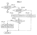
- FIGS. 4 to 7 show flow charts illustrating the basis sequence of operations of the occupant restraint system 1 of the preferred embodiment, with the operation of the system 1 being described below in conjunction with respective paths (i.e. the first path to the third path ). First, a detailed description is given to the first path.
- the impact detector unit 3 and the control unit 4 are turned on to start the operation.
- the impact detector unit 3 outputs DATA 0 (0, 0, 0) from the transmitter 10 to the control unit 4.
- the receiver 11 receives this DATA 0 which in turn is delivered to the receiving information discriminating section 12, which consequently discriminates that the current state remains in NORMAL STAGE.
- STATUS refers to a parameter that represents the status of the various stages discussed above.
- PATH refers to a particular parameter indicative of particular route through which the transition process shifts in the various stages, and the word “NUM (DATAn)” represents the number of times wherein DATAn is referred to.
- STATUS remains in NORMAL STAGE, which corresponds to YES in step ST 010 in FIG. 4, and the operation goes to step ST 020 where it is discriminated whether DATA 1 is received.
- the operational state judgment is turned ON such that the impact detector unit 3 outputs DATA 1 (0, 0, 1) as indicated by YES in step ST 020. Then, the impact detector unit 3 sets NUM (DATA 2) to binary "0" while incrementing NUM (DATA 1) in step ST 021.
- STATUS is not in the NORMAL STAGE, as indicated by NO in step ST 010 and remains in STAGE 1-A, as indicated by YES in step ST 110 in FIG. 5.
- DATA 3 (0, 1, 1) is applied in step ST 120.
- the calculation start judgment is turned ON, providing DATA 3 (0, 1, 1) as shown by YES in step ST 120 for incrementing NUM (DATA 3) in step ST121. Then, in the presence of the reference to DATA 3 (0, 1, 1) three times, as indicated by YES in step ST 122, the impact detector unit 3 shifts the stage from
- PATH (0, 0, 0, 0, 1, 0, 1, 0).
- step ST310 the result of step ST310 in FIG. 7 becomes YES.
- step ST 320 it is discriminated whether such DATA is referred to at once and, if so, step ST 320 represents YES.
- step ST 322 the control unit 4 discriminates that it is an error, precluding the occupant restraint device 2 from being deployed.
- the presence of utilization of the transition progress along the first path allows the occupant restraint device 2 to be deployed at a remarkably high precision.
- step ST 010 in FIG. 4 represents YES
- step ST 020 represents NO
- step ST 030 represents YES.
- step STATUS STAGE 1-B
- the result of step ST 210 in FIG. 6 is represented by YES.
- the operative state judgment is turned ON. If, in this instance, DATA A3 (0, 1, 1) is transmitted to the control unit 4 as indicated by YES in step ST 220, NUM (DATA4) is set to binary "0", while incrementing NUM (DATA 3) in step ST 221.
- step ST 310 the result of step ST 310 in FIG. 7 represents YES.
- DATA 6 (1, 1, 1) is transmitted to the control unit 4 from the impact detector unit 3.
- step ST 320 it is discriminated whether such DATA is referred to at once and, if so, step ST 320 represents NO while the result of step ST 330 is YES.
- the control unit 4 makes a determination that the proper path (i.e.
- step ST 322 the control unit 4 discriminates that it is an error, precluding the occupant restraint device 2 from being deployed.
- the presence of utilization of the transition progress along the second path allows the occupant restraint device 2 to be deployed at a remarkably high precision.
- the third path takes the same steps as the second path up to the STAGE 1-B, and, therefore, a detailed description of the steps up to step ST 033 is herein omitted.
- step ST 310 in FIG. 7 becomes NO and the operation goes to step ST410 in FIG. 8.
- step ST 410 the operational state judgment is turned ON
- DATA 7 (1, 1, 1) is applied to the control unit 4 as indicated by YES in step ST 410.
- the control unit 4 makes a determination that the proper path (i. e. the third path) has elapsed, thereby producing the actuation signal to actuate the occupant restraint device 2 in step ST 412.
- the control unit 4 discriminates that it is an error, precluding the occupant restraint device 2 from being deployed.
- the presence of utilization of the transition progress along the third path allows the occupant restraint device 2 to be deployed at a remarkably high precision.
- control unit 4 if the control unit 4 is neither applied with DATA 1 nor DATA 2, the control unit 4 set both NUM (DATA 1) and NUM (DATA 2) to binary "0" in step ST 040.
- NUM (DATA 3) is set to binary "0" in step ST 130.
- STAGE 1-B if DATA 3 or DATA 4 are not received, then, the both NUM (DATA 3) and NUM (DATA 4) are set to binary "0" in step ST 240.
- control unit 4 makes a determination that there is no need for actuating the occupant restraint device 2 while allowing the operation to be shifted to NORMAL STAGE.
- control unit 4 is programmed to implement comparison between path information contained in the output signals transmitted from the impact detector unit 3 and associated path information stored in the control unit 4 to produce the actuation signal only when coincidence exists between relevant path information items.
- data reference is carried out three times for the transition progress up to STAGE 2-A or STAGE 2-B
- the present invention is not limited thereto and data reference may be carried out at one time, two times, or more than four times.
Landscapes
- Engineering & Computer Science (AREA)
- Mechanical Engineering (AREA)
- Air Bags (AREA)
- Automotive Seat Belt Assembly (AREA)
Abstract
Description
- The present invention relates to occupant restraint systems, such as an air bag and a pretensioner of a seat belt, mounted in a vehicle and, more particularly, an occupant restraint system and a method for operating the same for precluding an occupant restraint device from being improperly operated due to adverse effect caused by noises.
- It has been a usual practice for an occupant restraint system of a vehicle to have an impact detector section, which detects impact, and a control section which controls the actuation of an occupant restraint device, with the impact detector section and the control section being mechanically separate from one another and electrically connected to one another by means of a communication line. When the impact detector section detects impact exerted to the vehicle and discriminates a need for operating the occupant restraint device, the impact detector section transmits an actuation demand signal to the control section via the communication line. Upon receipt of the actuation demand signal, the control section instantaneously deploys the occupant restraint device for thereby restraining the occupant in a safe condition.
- During such operation, the presence of the communication line connected between the impact detector section and the control section is apt to cause an adverse effect on a proper operation of the restraint device owing to noises on the communication line. One technology for addressing such an issue is disclosed in Japanese Patent Provisional Publication No. 9-240419 (which will be hereinafter referred to as a related art).
- The technology disclosed in the above Publication is to produce communication signals at different number of output frequencies in an impact detector section while classifying a process, through which restraint judgment is implemented upon discriminating impact, into a plurality of stages which are allocated with particular output frequencies, respectively. Then, the impact detector section transmits output signals to the control section at the relevant frequencies associated with respective judgment stages. The control section executes discrimination for the frequencies of the received signals and deploys the occupant restraint device when the signals are received from the impact detector section in a predetermined sequence.
- However, upon receipt of the actuation signal, for the occupant restraint device, delivered from the impact detector section, although it is desirable for the control section to instantaneously allow the occupant restraint device to be deployed, the control section of the related art must receive the output signals from the impact detector section for a prolonged period of time in order to appropriately discriminate the output frequencies of the received signals from one another. To preclude the adverse affect caused by temporary variation in the output frequencies of the received signals containing noises, it is required for the control section to receive the signals from the impact detector section for a further prolonged period of time.
- The present invention has been made with a view to addressing the above issue and has an object of the present invention to provide an occupant restraint system and a method for operating the same which is able to preclude the system from being adversely affected with noises while enabling an occupant restraint device to be instantaneously deployed upon receipt of a restraint actuation signal from an impact detector unit.
- In accordance with one aspect, the present invention provides an occupant restraint system for a vehicle having an occupant restraint device to permit the occupant restraint device to be deployed for restraining the occupant in the vehicle when impact, exerted to the vehicle, is detected, said system comprising: an impact detector unit including an impact sensor detecting impact exerted to a vehicle to provide a sensory output representative of an impact status, said impact detector unit being responsive the impact status for providing at least two discriminating factors based on which at least two predetermined transition processes are programmed, to cause said occupant restraint device to be deployed, and producing information representing ON/OFF state of said discriminating factors involving transition process information representing said transition processes; and a control unit outputting an actuation signal to said occupant restraint device when a coincidence between a variation in said information, representing said ON/OFF state, received from said impact detector unit, and said transition process information involved in said information representing said ON/OFF state is confirmed.
- In accordance with another aspect, the present invention provides an occupant restraint system for a vehicle having an occupant restraint device to permit the occupant restraint device to be deployed for restraining the occupant in the vehicle when impact, exerted to the vehicle, is detected, said system comprising: an impact detector unit including at least two impact sensors detecting impact exerted to a vehicle to provide sensory outputs representative of impact status, said impact detector unit being responsive the impact status for providing at least two discriminating factors based on which at least two predetermined transition processes are programmed, to cause said occupant restraint device to be deployed, and producing information representing ON/OFF state of said discriminating factors involving transition process information representing said transition processes; and a control unit outputting an actuation signal to said occupant restraint device when a coincidence between a variation in said information representing said ON/OFF state, received from said impact detector unit, and said transition process information involved in said information representing said ON/OFF state is confirmed.
- In other words, the present invention provides an occupant restraint system for a vehicle having an occupant restraint device to permit the occupant restraint device to be deployed for restraining the occupant in the vehicle when impact, exerted to the vehicle, is detected, said system comprising: impact detecting means detecting impact exerted to a vehicle to provide a sensory output representative of an impact status, said impact detecting means being responsive the impact status for providing at least two discriminating factors based on which at least two predetermined transition processes are programmed, to cause said occupant restraint device to be deployed, and producing information representing ON/OFF state of said discriminating factors involving transition process information representing said transition processes; and control means outputting an actuation signal to said occupant restraint device when a coincidence between a variation in said information representing said ON/OFF state, received from impact detecting means, and said transition process information involved in said information representing said ON/OFF state is confirmed.
- In still other words, the present invention provides an occupant restraint system for a vehicle having an occupant restraint device to permit the occupant restraint device to be deployed for restraining the occupant in the vehicle when impact, exerted to the vehicle, is detected, said system comprising: impact detecting means including at least two impact sensors detecting impact exerted to a vehicle to provide sensory outputs representative of impact status, said impact detecting means being responsive the impact status for providing at least two discriminating factors based on which at least two predetermined transition processes are programmed, to cause said occupant restraint device to be deployed, and producing information representing ON/OFF state of said discriminating factors involving transition process information representing said transition processes; and control means outputting an actuation signal to said occupant restraint device when a coincidence between a variation in said information representing said ON/OFF state, received from said impact detecting means, and said transition process information involved in said information representing said ON/OFF state is confirmed.
- In accordance with still another aspect, the present invention includes a method for operating an occupant restraint system for a vehicle having an occupant restraint device to permit the occupant restraint device to be deployed for restraining the occupant in the vehicle when impact, exerted to the vehicle, is detected, said method comprising: detecting impact exerted to a vehicle to provide a sensory output representative of an impact status; preparing at least two discriminating factors based on which at least two predetermined transition processes are settled to cause said occupant restraint device to be deployed; producing information representing ON/OFF state of said discriminating factors involving transition process information representing said transition processes; and outputting an actuation signal to said occupant restraint device when a coincidence between a variation in said information representing said ON/OFF state and said transition process information involved in said information representing said ON/OFF state is confirmed.
- In accordance with yet another aspect, the present invention includes a method for operating an occupant restraint system for a vehicle having an occupant restraint device to permit the occupant restraint device to be deployed for restraining the occupant in the vehicle when impact, exerted to the vehicle, is detected, said method comprising: detecting impact exerted to a vehicle using at least two impact sensors to provide sensory outputs representative of impact status; preparing at least two discriminating factors based on which at least two predetermined transition processes are programmed to cause said occupant restraint device to be deployed ; producing information representing ON/OFF state of said discriminating factors involving transition process information representing said transition processes; and outputting an actuation signal to said occupant restraint device when a coincidence between a variation in said information representing said ON/OFF state and said transition process information involved in said information representing said ON/OFF state is confirmed.
-
- FIG. 1 is a block diagram illustrating a structure of an occupant restraint system of a preferred embodiment according to the present invention;
- FIG. 2 is a table illustrating the relationship between relevant statuses of respective discriminating factors and transmitted data;
- FIG. 3 is a view illustrating a transition process in respective stages;
- FIG. 4 is a first view component illustrating a first part of a basic sequence of operation of the occupant restraint system of the preferred embodiment shown in FIG. 1;
- FIG. 5 is a second view component illustrating a second part of the basic sequence of operation of the occupant restraint system of the preferred embodiment shown in FIG. 1;
- FIG. 6 is a third view component illustrating a third part of the basic sequence of operation of the occupant restraint system of the preferred embodiment shown in FIG. 1;
- FIG. 7 is a fourth view component illustrating a fourth part of the basic sequence of operation of the occupant restraint system of the preferred embodiment shown in FIG. 1;
- FIG. 8 is a fifth view component illustrating a fifth part of the basic sequence of operation of the occupant restraint system of the preferred embodiment shown in FIG. 1; and
- FIG. 9 is a view illustrating typical example of the transition process among correlated stages.
-
- To describe the present invention more in detail, a representation of the present invention is schematically shown in FIG. 1 as an occupant restraint system, for a vehicle, of a preferred embodiment.
- The
restraint system 1 includes arestraint device 2. The restraint device may be comprised of one of or any combination of devices. For, example, therestraint device 2 may be actuatable occupant restraint device that is mounted in the vehicle for restraining a vehicle occupant when the vehicle encounters an impact. Examples of such an occupant restraint device include an air bag device, a seat belt lock, and a seat belt pretensioner. Thesystem 1 further includes animpact detector unit 3 which detects a front impact, a side impact, or rollover (turnover) as a characteristic that is used to determine whether a vehicle occupant is to be restrained, and acontrol unit 4 for applying an actuation signal to therestraint device 2 when impact is detected with theimpact detector unit 3. To this end, theimpact detector unit 3 and thecontrol unit 4 are electrically connected through acommunication line 5. - The
impact detector unit 3 is comprised of first and second acceleration sensors (impact sensors) 6a, 6b that detect impact exerted to the vehicle for producing first and second sensory outputs, respectively, in response thereto, an actuation timingdiscriminating section 7 responsive to the first sensory output for discriminating an actuation timing at which theoccupant restraint device 2 is deployed, and an operational statediscriminating section 8 responsive to the second sensory output for discriminating if a deployment impact condition is occurring for actuating therestraint device 2. - The
occupant restraint system 1 further includes a transmitting informationdiscriminating section 9 which responds to outputs of the actuation timingdiscriminating section 7 and the operational statediscriminating section 8 to discriminate variations in respective discriminating factors (involving an actuation demand timing judgment, a calculation start judgment, and an operative state judgment) for producing data representative of such discriminating factors, and atransmitter 10 which transmits data produced from the transmitting informationdiscriminating section 9 to thecontrol unit 4 via thecommunication line 5. - The actuation timing
discriminating section 7 serves to execute two functions, i.e. the actuation demand timing judgment and the calculation start judgment. Among these functions, the actuation demand timing judgment is turned ON when an integral result of the sensory output of thefirst acceleration sensor 6a exceeds a first threshold value. Further, the calculation start judgment is turned ON when the sensory output of thefirst acceleration sensor 6a exceeds a second threshold value. - The operational state
discriminating section 8 is turned ON when an integral result of the sensory output of thesecond acceleration sensor 6b exceeds a third threshold value. For the purpose of illustration of the invention and not for the purpose of limitation, the first and third threshold values are exemplarily settled to be substantially identical to one another to cause the sample shown in FIG. 1 to operate in two modes, i.e. a first mode wherein the actuation demand timing judgment is first turned on owing to sensitive characteristic of the first andsecond acceleration sensors - On the other hand, the
control unit 4 is comprised of areceiver 11 which receives data representative of the discriminating factors transmitted from theimpact detector unit 3, a receiving informationdiscriminating section 12 which is arranged to have a plurality of preliminarily programmed transition processes to be compared with relevant transition processes contained data, representative of the discriminating factors, received by thereceiver 11 with a view to making determination as to whether the preliminarily programmed transition processes coincide with the transition processes preset in data representative of the discriminating factors for producing a coincidence signal when these parameters coincide with one another, and a restraintactuator control section 13 which outputs a trigger signal on theoccupant restraint devices 2 in response to the coincidence signal delivered from the receiving information discriminating section. - Now, the variation of the aforementioned discriminatiing factors is described below in detail with reference to FIG. 2.
- FIG. 2 shows a table illustrating the relationship among ON/OFF states of the respective discriminating factors (i.e. the actuation demand timing judgment, the calculation start judgment, and the operative state judgment), correlated transmitting data (involving DATA1 to DATA7) and associated stages (which will be discussed later in detail). It is to be noted that binary values "1" and "0" are assigned to an "ON" state and an "OFF" state of the discriminating factors, respectively.
- When both the first and
second acceleration sensors DATA 0 is represented by three decimal numbers (0, 0, 0). Also, the three decimal numbers (0, 0, 0) represent the actuation demand timing judgment, the calculation start judgment and the operative state judgment, respectively, in sequence from the left. - Further, in a case where the integral result of the sensory output produced by the
second acceleration sensor 6b exceeds the third threshold value, the operative state judgment is turned ON and, so,DATA 1 is represented by the three decimal numbers (0, 0, 1). Similarly,DATA 2 is represented by the three decimal numbers (0, 1, 0),DATA 3 is represented by the three decimal numbers (0, 1, 1),DATA 4 is represented by the three decimal numbers (1, 1, 0), andDATA 5 toDATA 7 are represented by the three decimal numbers (1,1,1). - Also, it is to be noted that there are physically no cases of the three decimal numbers (1, 0, 0) and (1, 0, 1). That is, since the calculation start judgment is turned ON at a timing earlier than the actuation demand timing judgment, there are no possibilities where the three decimal numbers (1, 0, 0) and (1, 0, 1) exist. Further, the results of respective judgments are irreversible such that once a particular judgment is turned ON, i.e. the binary "1", the particular judgment does not revert to the binary "0" (OFF) state.
- Various patterns of the transition processes that vary in dependence on the respective discriminating factors are described below in detail with reference to FIG. 3. The receiving
information discriminating section 12 stores preliminarily programmed stages, representing the transition processes, such as NORMAL STAGE, STAGE 1-A, STAGE 1-B, STAGE 2-A, STAGE 2-B, and FINAL STAGE. Also stored in the receiving informationdiscriminating section 12 are proper transition processes (including proper routes passing through the respective stages), such as a first path, a second path,and a third path. - As shown in FIG. 3, the first path represents a path wherein the transition process shifts through NORMAL STAGE, STAGE 1-A, STAGE 2-A, and FINAL STAGE in a sequence. Likewise, the second path represents a path wherein the transition process shifts through NORMAL STAGE, STAGE 1-B, STAGE 2-A, and FINAL STAGE. Similarly, the third path represents a path wherein the transition process shifts through NORMAL STAGE, STAGE 1-B, STAGE 2-B, and FINAL STAGE. Also, the transition occurs among the various stages in a manner as shown in FIG. 9.
- As shown in FIG. 3, three patterns of
DATA 5 toDATA 7 involving the operative state judgment are prepared with a view to permitting data representative of the operative state judgment to include proper path information, enabling theimpact detector unit 3 to distinguish data from one another depending on the particular transition processes that have shifted from STAGE 2-A or STAGE 2-B to FINAL STAGE. - That is, in a case where the transition process occurs in the first path,
DATA 5 is selected. In a case where the transition process occurs in the second path,DATA 6 is selected and, in case of the third path,DATA 7 is selected. - FIGS. 4 to 7 show flow charts illustrating the basis sequence of operations of the
occupant restraint system 1 of the preferred embodiment, with the operation of thesystem 1 being described below in conjunction with respective paths (i.e. the first path to the third path ). First, a detailed description is given to the first path. - First, when an ignition switch of the vehicle is turned on, the
impact detector unit 3 and thecontrol unit 4 are turned on to start the operation. - In the absence of any impact exerted to the vehicle, all the actuation demand timing judgment, the calculation start judgment and the operational state judgment remain in the OFF states. Under this circumstance, the
impact detector unit 3 outputs DATA 0 (0, 0, 0) from thetransmitter 10 to thecontrol unit 4. Thereceiver 11 receives thisDATA 0 which in turn is delivered to the receivinginformation discriminating section 12, which consequently discriminates that the current state remains in NORMAL STAGE. - The receiving
information discriminating section 12 is programmed to have an initial state with STATUS = NORMAL, PATH = 00 h = 00000000 (1 byte data), and NUM (DATAn) = 00 h (1 byte DATA). Here, the word "STATUS" refers to a parameter that represents the status of the various stages discussed above. The word "PATH" refers to a particular parameter indicative of particular route through which the transition process shifts in the various stages, and the word "NUM (DATAn)" represents the number of times wherein DATAn is referred to. - Under an initial condition, STATUS remains in NORMAL STAGE, which corresponds to YES in step ST 010 in FIG. 4, and the operation goes to step ST 020 where it is discriminated whether
DATA 1 is received. - In case of the vehicle encountering impact or rollover (turnover), if the integral result of the sensory output of the
second acceleration sensor 6b exceeds the third threshold value, the operational state judgment is turned ON such that theimpact detector unit 3 outputs DATA 1 (0, 0, 1) as indicated by YES in step ST 020. Then, theimpact detector unit 3 sets NUM (DATA 2) to binary "0" while incrementing NUM (DATA 1) in step ST 021. - In case of NUM (DATA 1) = 3, i.e. when DATA 1(0, 0, 1) is successively referred to three times as shown by YES in step ST 022, the
impact detector unit 3 shifts the stage from NORMAL STAGE to STAGE 1-A, i.e. STATUS = STAGE 1-A. Also, a second digit of a binary 8 digits indicating PATH is set to binary "1" in step ST 023, i.e. PATH = (0, 0, 0, 0, 0, 0, 1, 0). A second digit of PATH indicated in the binary 8 digits is set to binary "1" responsive toDATA 1. In this respect, whenDATA 2 is applied, a third digit is set to binary "1", and whenDATA 3 is applied, a fourth digit is set to binary "1". Likewise, whenDATA 4 is applied, a fifth digit is set to binary "1". - In a consecutive operation, STATUS is not in the NORMAL STAGE, as indicated by NO in step ST 010 and remains in STAGE 1-A, as indicated by YES in step ST 110 in FIG. 5. When this takes place, it is discriminated whether DATA 3 (0, 1, 1) is applied in step ST 120.
- Focusing now on a particular case wherein the sensory output of the
first acceleration sensor 6a exceeds the second threshold value, the calculation start judgment is turned ON, providing DATA 3 (0, 1, 1) as shown by YES in step ST 120 for incrementing NUM (DATA 3) in step ST121. Then, in the presence of the reference to DATA 3 (0, 1, 1) three times, as indicated by YES in step ST 122, theimpact detector unit 3 shifts the stage from - STAGE 1-A to STAGE 2-A, i.e. STATUS = STAGE 2-A, while setting a fourth digit of PATH to binary "1", i.e. PATH = (0, 0, 0, 0, 1, 0, 1, 0).
- Subsequently, since STATUS = STAGE 2-A, the result of step ST310 in FIG. 7 becomes YES. Here, if the integral result of the sensory output of the
first acceleration sensor 6a exceeds the first threshold value, DATA 5 (1, 1, 1) is transmitted. Thus, in step ST 320, it is discriminated whether such DATA is referred to at once and, if so, step ST 320 represents YES. Then, the operation goes to step ST 321 where it is discriminated whether the status remains in PATH = (0, 0, 0, 0, 1, 0, 1, 0). If, in this case, the result is YES, thecontrol unit 4 makes a determination that the proper path (i. e. the first path) has elapsed, thereby producing the output to actuate theoccupant restraint device 2 in step ST 322. On the contrary, in the absence of PATH = (0, 0, 0, 0, 1, 0, 1, 0) as indicated by NO in step ST 321, thecontrol unit 4 discriminates that it is an error, precluding theoccupant restraint device 2 from being deployed. - Thus, the presence of utilization of the transition progress along the first path allows the
occupant restraint device 2 to be deployed at a remarkably high precision. - Focusing next to the second path, in the presence of NORMAL STAGE (with no impact being detected), if the sensory output of the
first acceleration sensor 6a exceeds the second threshold value, then, the calculation start judgment is turned on. When this occurs, DATA 2 (0, 1, 0) is output from theimpact detector unit 3 to thecontrol unit 4. That is, the result of step ST 010 in FIG. 4 represents YES, the result of step ST 020 represents NO, and the result of step ST 030 represents YES. - Under such a case, in step ST 031, the
impact detector unit 3 sets NUM (DATA 1) to binary "0" while incrementing NUM (DATA 2). Further, in the presence of the references executed three times for DATA 2 (0, 1, 0), then, the result of step ST 032 is represented by YES, thereby shifting the stage from NORMAL STAGE to STAGE 1-B, i.e. STATUS = STAGE 1-B. Also, the third digit of the PATH is set to binary "1", i.e. PATH = (0, 0, 0, 0, 0, 1, 0, 0). - Consecutively, since STATUS = STAGE 1-B, the result of step ST 210 in FIG. 6 is represented by YES. Then, the operative state judgment is turned ON. If, in this instance, DATA A3 (0, 1, 1) is transmitted to the
control unit 4 as indicated by YES in step ST 220, NUM (DATA4) is set to binary "0", while incrementing NUM (DATA 3) in step ST 221. Subsequently, upon confirmation of the reference executed three times for DATA 3 (0, 1, 1) as indicated by YES in step ST 222, theimpact detector unit 3 shifts the stage from STAGE 1-B to STAGE 2-B to represent STATUS = STAGE 2-A. In this instant, the fourth digit of PATH is set to "1", i.e. PATH = (0, 0, 0, 0, 1, 1, 0, 0). - Successively, since STATUS = STAGE 2-A, the result of step ST 310 in FIG. 7 represents YES. Here, if the integral result of the sensory output of the
first acceleration sensor 6a exceeds the first threshold value, DATA 6 (1, 1, 1) is transmitted to thecontrol unit 4 from theimpact detector unit 3. When this occurs, in step ST 320, it is discriminated whether such DATA is referred to at once and, if so, step ST 320 represents NO while the result of step ST 330 is YES, When data of PATH , i.e. when the status PATH = (0, 0, 0, 0, 1, 1,0, 0) exists, the result is YES in step ST 331. When this takes place, thecontrol unit 4 makes a determination that the proper path (i.e. the second path) has elapsed , thereby producing the actuation signal to deploy theoccupant restraint device 2 in step ST 322. On the contrary, in the absence of PATH = (0, 0, 0, 0, 1, 1,0 0) as indicated by NO in step ST 331, thecontrol unit 4 discriminates that it is an error, precluding theoccupant restraint device 2 from being deployed. - Thus, the presence of utilization of the transition progress along the second path allows the
occupant restraint device 2 to be deployed at a remarkably high precision. - Focusing lastly to the third path, the third path takes the same steps as the second path up to the STAGE 1-B, and, therefore, a detailed description of the steps up to step ST 033 is herein omitted.
- After the transition progress reaches STAGE 1-B, as shown by YES in step ST 210 in FIG. 6, if the actuation demand timing judgment is turned ON, the
impact detector unit 3 outputs DATA 4 (1, 1, 0) as represented by NO in step ST 220 and by YES in step ST 230, thereby setting NUM (DATA 3) to binary "1" and incrementing NUM (DATA 4) in step ST 231. Subsequently, if the presence of the references executed three times for DATA 4 (1, 1, 0), as represented by YES in step ST 232, then, the stage is shifted from STAGE 1-B to STAGE 2-B, i.e. STATUS = STAGE 2-B. Also, the fifth digit of the PATH is set to binary "1", i.e. PATH = (0, 0, 0, 1, 0, 1, 0, 0) in step ST 233. - Consecutively, since STATUS = STAGE 2-B, the result of step ST 310 in FIG. 7 becomes NO and the operation goes to step ST410 in FIG. 8. If, in this instance, the operational state judgment is turned ON, DATA 7 (1, 1, 1) is applied to the
control unit 4 as indicated by YES in step ST 410. If PATH data is discriminated to be PATH = (0, 0, 0, 1, 0, 1,0, 0) as indicated by YES in step ST 411, thecontrol unit 4 makes a determination that the proper path (i. e. the third path) has elapsed, thereby producing the actuation signal to actuate theoccupant restraint device 2 in step ST 412. On the contrary, in the absence of PATH = (0, 0, 0, 1, 0, 1,0 0) as indicated by NO in step ST 411, thecontrol unit 4 discriminates that it is an error, precluding theoccupant restraint device 2 from being deployed. - Thus, the presence of utilization of the transition progress along the third path allows the
occupant restraint device 2 to be deployed at a remarkably high precision. - Further, in NORMAL STAGE, if the
control unit 4 is neither applied withDATA 1 norDATA 2, thecontrol unit 4 set both NUM (DATA 1) and NUM (DATA 2) to binary "0" in step ST 040. In STAGE 1-A, ifDATA 3 is not received, then, NUM (DATA 3) is set to binary "0" in step ST 130. Likewise, in STAGE 1-B, ifDATA 3 orDATA 4 are not received, then, the both NUM (DATA 3) and NUM (DATA 4) are set to binary "0" in step ST 240. - In addition, although no description has been made in conjunction with the flow charts, the absence of the variation in received data for a predetermined time interval of, for example, more than 150 ms during a time period wherein the
control unit 4 is applied with data exceptDATA 0 representative of the transition progress prior to impact being exerted to the vehicle, thecontrol unit 4 makes a determination that there is no need for actuating theoccupant restraint device 2 while allowing the operation to be shifted to NORMAL STAGE. - It will thus be appreciated from the foregoing description that, in accordance with the occupant restraint system of the present invention, appropriate deployment variables are based on the discriminating factors involving the actuation demand timing judgment, the calculation start judgment, and the operational state judgment, which represent the status of impact exerted to the vehicle, and whose ON/OFF states are correlated with the various paths (i.e. the first path to the third path) representative of the particular transition progresses for respective stages. The
control unit 4 is programmed to implement comparison between path information contained in the output signals transmitted from theimpact detector unit 3 and associated path information stored in thecontrol unit 4 to produce the actuation signal only when coincidence exists between relevant path information items. As a consequence, even in the presence of noise superimposed on the communication signals passing through thecommunication line 5 between theimpact detector unit 3 and thecontrol unit 4, it is possible for theoccupant restraint system 1 to be appropriately deployed without causing any erroneous operation. - Further, in the progress of transition from STAGE 2-A to STAGE 2-B, the presence of identical data received at three times by the
control unit 4 is confirmed, with a resultant increased precision in transmission of the output signals. Furthermore, during a transition period from STAGE 2-A or STAGE 2-B to the FINAL STAGE, since the number of data reference is programmed to be one time, data reference can be implemented in a rapid manner, enabling theoccupant restraint device 2 to be instantaneously deployed. With such specific arrangement, the vehicle may have a further improved safety circumference. - While the present invention has been described above with reference to the vehicle occupant restraint system of a particular embodiment and the method of operating the occupant restraint device, the present invention is not limited to the particular embodiment and those skilled in the art will perceive improvements, changes and modifications.
- For example, in the preferred embodiment, although the detailed description has been given above with respect to the example wherein data reference is carried out three times for the transition progress up to STAGE 2-A or STAGE 2-B, the present invention is not limited thereto and data reference may be carried out at one time, two times, or more than four times.
- The entire content of Japanese Application No. P2001-80679 with a filing date of March 21, 2001 is herein incorporated by reference.
- Although the present invention has been described above by reference to certain embodiments of the invention, the invention is not limited to the embodiments described above and modifications will occur to those skilled in the art, in light of the teachings. The scope of the invention is defined with reference to the following claims.
Claims (8)
- An occupant restraint system (1) for a vehicle having an occupant restraint device (2) to permit the occupant restraint device to be deployed for restraining the occupant in the vehicle when impact, exerted to the vehicle, is detected, said system comprising:an impact detector unit (3) including an impact sensor (6a, 6b) detecting impact exerted to a vehicle to provide a sensory output representative of an impact status, said impact detector unit being responsive the impact status for providing at least two discriminating factors based on which at least two predetermined transition processes are programmed, to cause said occupant restraint device to be deployed, and producing information representing ON/OFF state of said discriminating factors involving transition process information representing said transition processes; anda control unit (4) outputting an actuation signal to said occupant restraint device when a coincidence between a variation in said information representing said ON/OFF state, received from said impact detector unit, and said transition process information involved in said information representing said ON/OFF state is confirmed.
- An occupant restraint system (1) for a vehicle having an occupant restraint device to permit the occupant restraint device (2) to be deployed for restraining the occupant in the vehicle when impact, exerted to the vehicle, is detected, said system comprising:an impact detector unit (3) including at least two impact sensors (6a, 6b) detecting impact exerted to a vehicle to provide sensory outputs representative of impact status, said impact detector unit being responsive the impact status for providing at least two discriminating factors based on which at least two predetermined transition processes are programmed, to cause said occupant restraint device to be deployed, and producing information representing ON/OFF state of said discriminating factors involving transition process information representing said transition processes; anda control unit (4) outputting an actuation signal to said occupant restraint device when a coincidence between a variation in said information representing said ON/OFF state, received from said impact detector unit, and said transition process information involved in said information representing said ON/OFF state is confirmed.
- The occupant restraint system according to claim 2, wherein:wherein said discriminating factors include an actuation demand timing judgment which is turned on when an integral result of a sensory output of said first impact sensor exceeds a first threshold value, a calculation start judgment which is turned on when the sensory output of said first impact sensor exceeds a second threshold value, and an operational state judgment which is turned on when an integral result of a sensory output of said second impact sensor exceeds a third threshold value.said impact detector unit includes a first impact sensor (6a) and a second impact sensor (6b); and
- The occupant restraint system according to claim 3, wherein:said first and second threshold values are settled to be substantially identical to one another.
- The occupant restraint system according to claims 3 or 4, wherein:wherein said control unit is operative to deploy said occupant restraint device when said discriminating factors reach said FINAL STAGE.said transition process includes a plurality of stages representing said discriminating factors, respectively; andwherein said stages includes:a NORMAL STAGE settled to represent that all of said discriminating factors are turned off;a FIRST-A STAGE settled to represent that operative state judgment is turned on subsequent to said NORMAL;a FIRST-B STAGE settled to represent that calculation start judgment is turned on subsequent to said NORMAL STAGE;a SECOND-A STAGE settled to represent that said calculation start judgment is turned on subsequent to said FIRST-A STAGE or that said operative state judgment is turned on subsequent to said FIRST-B STAGE;a SECOND-B STAGE settled to represent that actuation demand timing judgment is turned on subsequent to said first-B STAGE; anda FINAL STAGE settled to represent that said actuation demand timing judgment is turned on subsequent to said SECOND-A STAGE or that said operative state judgment is turned on subsequent to said SECOND-B STAGE; and
- The occupant restraint system according to claim 5, wherein:transition between said NORMAL STAGE and said FIRST-A STAGE, transition between said NORMAL STAGE and said FIRST-B STAGE, transition between said FIRST-A STAGE and said SECOND-A STAGE, transition between said FIRST-B STAGE and said SECOND-A STAGE, and transition between said FIRST-B STAGE and said SECOND-B stage are carried out by referring to said discriminating factors a plurality of times; andtransition between said SECOND-A STAGE and said FINAL STAGE and transition between said SECOND-B STAGE and said FINAL STAGE are carried out by referring to said discriminating factors at least one time.
- A method for operating an occupant restraint system (1) for a vehicle having an occupant restraint device (2) to permit the occupant restraint device to be deployed for restraining the occupant in the vehicle when impact, exerted to the vehicle, is detected, said method comprising:detecting impact exerted to a vehicle to provide a sensory output representative of an impact status;preparing at least two discriminating factors based on which at least two predetermined transition processes are settled to cause said occupant restraint device to be deployed;producing information representing ON/OFF state of said discriminating factors involving transition process information representing said transition processes; andoutputting an actuation signal to said occupant restraint device when a coincidence between a variation in said information representing said ON/OFF state, received from said impact detector unit, and said transition process information involved in said information representing said ON/OFF state is confirmed.
- A method for operating an occupant restraint system (1) for a vehicle having an occupant restraint device (2) to permit the occupant restraint device to be deployed for restraining the occupant in the vehicle when impact, exerted to the vehicle, is detected, said method comprising:detecting impact exerted to a vehicle using at least two impact sensors to provide sensory outputs representative of impact status;preparing at least two discriminating factors based on which at least two predetermined transition processes are programmed to cause said occupant restraint device to be deployed ;producing information representing ON/OFF state of said discriminating factors involving transition process information representing said transition processes; andoutputting an actuation signal to said occupant restraint device when a coincidence between a variation in said information representing said ON/OFF state, received from said impact detector unit, and said transition process information involved in said information representing said ON/OFF state is confirmed.
Applications Claiming Priority (2)
| Application Number | Priority Date | Filing Date | Title |
|---|---|---|---|
| JP2001080679 | 2001-03-21 | ||
| JP2001080679A JP3642033B2 (en) | 2001-03-21 | 2001-03-21 | Crew restraint system |
Publications (2)
| Publication Number | Publication Date |
|---|---|
| EP1243478A1 true EP1243478A1 (en) | 2002-09-25 |
| EP1243478B1 EP1243478B1 (en) | 2005-05-18 |
Family
ID=18936917
Family Applications (1)
| Application Number | Title | Priority Date | Filing Date |
|---|---|---|---|
| EP02250905A Expired - Lifetime EP1243478B1 (en) | 2001-03-21 | 2002-02-11 | Occupant restraint system and method for operating the same |
Country Status (4)
| Country | Link |
|---|---|
| US (1) | US6722462B2 (en) |
| EP (1) | EP1243478B1 (en) |
| JP (1) | JP3642033B2 (en) |
| DE (1) | DE60204184T2 (en) |
Families Citing this family (5)
| Publication number | Priority date | Publication date | Assignee | Title |
|---|---|---|---|---|
| ITTO20030142A1 (en) * | 2003-02-28 | 2004-09-01 | St Microelectronics Srl | MULTIDIRECTIONAL INERTIAL MULTIPLE THRESHOLD DEVICE |
| US7636479B2 (en) * | 2004-02-24 | 2009-12-22 | Trw Automotive U.S. Llc | Method and apparatus for controlling classification and classification switching in a vision system |
| US20070168097A1 (en) * | 2006-01-18 | 2007-07-19 | Automotive Systems Laboratory, Inc. | Discrete hardware safing circuit |
| DE102007039835A1 (en) * | 2007-08-23 | 2009-02-26 | Robert Bosch Gmbh | Control unit and method for controlling personal protective equipment for a vehicle |
| US11590913B2 (en) * | 2019-06-20 | 2023-02-28 | Ford Global Technologies, Llc | Restraint monitoring system for a vehicle |
Citations (3)
| Publication number | Priority date | Publication date | Assignee | Title |
|---|---|---|---|---|
| US5749059A (en) * | 1995-09-14 | 1998-05-05 | Trw Technar Inc. | Apparatus and method for controlling an actuatable restraint device |
| US5969598A (en) * | 1996-07-17 | 1999-10-19 | Nissan Motor Co., Ltd. | Accident reporting system for a land vehicle |
| EP1040967A1 (en) * | 1999-03-30 | 2000-10-04 | Alps Electric Co., Ltd. | Air-bag control apparatus |
Family Cites Families (4)
| Publication number | Priority date | Publication date | Assignee | Title |
|---|---|---|---|---|
| JP3562105B2 (en) | 1996-03-01 | 2004-09-08 | 日産自動車株式会社 | Airbag control device |
| DE19740019A1 (en) * | 1997-09-11 | 1999-03-25 | Siemens Ag | Vehicle occupant protection device |
| DE19740021A1 (en) * | 1997-09-11 | 1999-03-25 | Siemens Ag | Vehicle occupant protection device |
| JP2000255373A (en) * | 1999-03-02 | 2000-09-19 | Mitsubishi Electric Corp | Vehicle collision detection device |
-
2001
- 2001-03-21 JP JP2001080679A patent/JP3642033B2/en not_active Expired - Fee Related
-
2002
- 2002-02-11 DE DE60204184T patent/DE60204184T2/en not_active Expired - Fee Related
- 2002-02-11 EP EP02250905A patent/EP1243478B1/en not_active Expired - Lifetime
- 2002-03-05 US US10/087,823 patent/US6722462B2/en not_active Expired - Fee Related
Patent Citations (3)
| Publication number | Priority date | Publication date | Assignee | Title |
|---|---|---|---|---|
| US5749059A (en) * | 1995-09-14 | 1998-05-05 | Trw Technar Inc. | Apparatus and method for controlling an actuatable restraint device |
| US5969598A (en) * | 1996-07-17 | 1999-10-19 | Nissan Motor Co., Ltd. | Accident reporting system for a land vehicle |
| EP1040967A1 (en) * | 1999-03-30 | 2000-10-04 | Alps Electric Co., Ltd. | Air-bag control apparatus |
Also Published As
| Publication number | Publication date |
|---|---|
| DE60204184D1 (en) | 2005-06-23 |
| US6722462B2 (en) | 2004-04-20 |
| JP2002274317A (en) | 2002-09-25 |
| DE60204184T2 (en) | 2006-02-02 |
| JP3642033B2 (en) | 2005-04-27 |
| EP1243478B1 (en) | 2005-05-18 |
| US20020134608A1 (en) | 2002-09-26 |
Similar Documents
| Publication | Publication Date | Title |
|---|---|---|
| JP3528440B2 (en) | In-vehicle information communication device | |
| US6943669B2 (en) | Method for transmitting data from at least one sensor to a control unit | |
| US7137645B2 (en) | Control device for a restraining system in a motor vehicle | |
| EP1305191B1 (en) | Airbag trigger control system | |
| EP1024977A1 (en) | Crash detection system | |
| JP3438217B2 (en) | Method and apparatus for controlling data transmission between two modules provided in a motor vehicle | |
| US20050107933A1 (en) | Airbag apparatus | |
| US20030160436A1 (en) | Method of triggering at least one airbag in a vehicle | |
| EP1243478B1 (en) | Occupant restraint system and method for operating the same | |
| JP2000190808A (en) | Occupant protection device | |
| GB2428123A (en) | Vehicle impact protection system | |
| US7337048B2 (en) | Vehicular occupant protection system | |
| US20080046148A1 (en) | Control Apparatus for Occupant Restraint Device | |
| KR101006094B1 (en) | Airbag control unit | |
| WO2018224228A1 (en) | Voice shifting | |
| JP4650690B2 (en) | Bus communication system | |
| US6970778B1 (en) | Passenger restraint system for a motor vehicle | |
| US20070132314A1 (en) | Device and method for the disposal/disposal firing of occupant protection devices/road user protection devices with pyrotechnic igniters | |
| JP3719371B2 (en) | Vehicle occupant protection system | |
| JP4457311B2 (en) | Vehicle occupant protection device | |
| JP6893585B2 (en) | How to determine the deactivated operating state of a car | |
| EP1040967B1 (en) | Air-bag control apparatus | |
| JP4380547B2 (en) | Activation control device and activation method for occupant protection device | |
| EP2112029B1 (en) | Occupant protection control device and occupant protection system | |
| EP1859998A1 (en) | Actuator of crew protector |
Legal Events
| Date | Code | Title | Description |
|---|---|---|---|
| PUAI | Public reference made under article 153(3) epc to a published international application that has entered the european phase |
Free format text: ORIGINAL CODE: 0009012 |
|
| 17P | Request for examination filed |
Effective date: 20020220 |
|
| AK | Designated contracting states |
Kind code of ref document: A1 Designated state(s): AT BE CH CY DE DK ES FI FR GB GR IE IT LI LU MC NL PT SE TR |
|
| AX | Request for extension of the european patent |
Free format text: AL;LT;LV;MK;RO;SI |
|
| AKX | Designation fees paid |
Designated state(s): DE FR GB |
|
| 17Q | First examination report despatched |
Effective date: 20040123 |
|
| GRAP | Despatch of communication of intention to grant a patent |
Free format text: ORIGINAL CODE: EPIDOSNIGR1 |
|
| GRAS | Grant fee paid |
Free format text: ORIGINAL CODE: EPIDOSNIGR3 |
|
| GRAA | (expected) grant |
Free format text: ORIGINAL CODE: 0009210 |
|
| AK | Designated contracting states |
Kind code of ref document: B1 Designated state(s): DE FR GB |
|
| REG | Reference to a national code |
Ref country code: GB Ref legal event code: FG4D |
|
| REG | Reference to a national code |
Ref country code: IE Ref legal event code: FG4D |
|
| REF | Corresponds to: |
Ref document number: 60204184 Country of ref document: DE Date of ref document: 20050623 Kind code of ref document: P |
|
| PLBE | No opposition filed within time limit |
Free format text: ORIGINAL CODE: 0009261 |
|
| STAA | Information on the status of an ep patent application or granted ep patent |
Free format text: STATUS: NO OPPOSITION FILED WITHIN TIME LIMIT |
|
| ET | Fr: translation filed | ||
| 26N | No opposition filed |
Effective date: 20060221 |
|
| PGFP | Annual fee paid to national office [announced via postgrant information from national office to epo] |
Ref country code: GB Payment date: 20070207 Year of fee payment: 6 |
|
| PGFP | Annual fee paid to national office [announced via postgrant information from national office to epo] |
Ref country code: DE Payment date: 20070208 Year of fee payment: 6 |
|
| PGFP | Annual fee paid to national office [announced via postgrant information from national office to epo] |
Ref country code: FR Payment date: 20070208 Year of fee payment: 6 |
|
| GBPC | Gb: european patent ceased through non-payment of renewal fee |
Effective date: 20080211 |
|
| REG | Reference to a national code |
Ref country code: FR Ref legal event code: ST Effective date: 20081031 |
|
| PG25 | Lapsed in a contracting state [announced via postgrant information from national office to epo] |
Ref country code: DE Free format text: LAPSE BECAUSE OF NON-PAYMENT OF DUE FEES Effective date: 20080902 |
|
| PG25 | Lapsed in a contracting state [announced via postgrant information from national office to epo] |
Ref country code: FR Free format text: LAPSE BECAUSE OF NON-PAYMENT OF DUE FEES Effective date: 20080229 |
|
| PG25 | Lapsed in a contracting state [announced via postgrant information from national office to epo] |
Ref country code: GB Free format text: LAPSE BECAUSE OF NON-PAYMENT OF DUE FEES Effective date: 20080211 |