-
The present invention relates to a printer for
printing on a printing medium by using an inkjet head
ejecting for ink.
-
The recent spread of digital cameras has resulted in
increasing needs for printing photographed images without
the intervention of a personal computer. Known apparatus
formed by integrating a camera and a printer include
Polaroid® cameras.
-
One possible approach to achieve functions similar
to those of such Polaroid cameras with a digital camera
is to configure a printer-built-in camera by integrating
a digital camera for photographing an image with a printer
for printing the photographed image. With such a
printer-built-in camera, a photographed image can be
printed any time without using any other apparatus.
-
In the case of a printer which must be compact and
light-weight, e.g., a printer integrated with a digital
camera, a printer consumable container for containing
printing media, ink and so on as printer consumable
supplies is used. The size of the printer may be increased
when the printer consumable container is always attached,
and it is therefore desirable to attach the container to
the printer as occasions demand. When such a container
is used, the container may be removed except during a
printing operation to improve the operability of the
printer or the camera.
-
On that account, an object of the present invention
is to provide a printer capable of achieving down sizing
and enhancing weight saving thereof.
-
In an aspect of the present invention, there is
provided a printer utilizing an inkjet recording head
ejecting ink and for performing printing by scanning the
inkjet recording head on a printing medium, the printer
comprising:
- an ink supply member which is provided so as to face
an end of a scanning area of the inkjet recording head and
which defines the end of an ink supply passage to the inkjet
recording head, the ink supply member being connected to
a reserving portion provided inside the inkjet recording
head when the inkjet recording head is located at the end
of the scanning area; and
- a suction member which is provided so as to face an
end of the scanning area of the inkjet recording head and
which defines a leading end of a suction passage exerting
a suction force for introducing ink into the reserving
portion from the ink supply member, the suction member
being connected to the reserving portion when the inkjet
recording head is located at the end of the scanning area,
wherein the ink supply member and the suction member
are provided such that one of the connection between the
reserving portion and the ink supply member and the
connection between the reserving portion and the suction
member is started prior to the other as a result of a
movement of the inkjet recording head toward the end of
the scanning area.-
-
Here, the ink supply member may have a joint allowing
a hollow needle provided at the reserving portion to be
stuck therein and the sticking of the hollow needle into
the joint may be started prior to the connection between
the reserving portion and the suction member.
-
The movement of the inkjet recording head toward the
end of the scanning area may take place with a period for
an approach run in the scanning area provided.
-
In addition to a driving force of a driving source
for performing the scanning, a driving force of another
driving source may be transmitted in withdrawing the inkjet
recording head from the end toward the scanning area.
-
Further, a pump for performing ink transport
operations associated with the inkjet recording head
including the introduction of ink into the reserving
portion by the action of the suction force and a driving
source for driving the pump may be comprised, and a driving
force of the driving source may be transmitted at the time
of the withdrawal.
-
A container of consumable supplies for a printer
containing consumable supplies used in performing
printing with the inkjet recording head may be attachable.
-
The container may have an ink containing portion for
containing ink to be replenished in the reserving portion.
-
The above and other objects, effects, features and
advantages of the present invention will become more
apparent from the following description of embodiments
thereof taken in con junction with the accompanying
drawings.
- Fig. 1 is a front view of a printer-built-in camera
to which the invention can be applied;
- Fig. 2 is a perspective view of the camera in Fig.
1 taken diagonally in front of the same;
- Fig. 3 is a perspective view of the camera in Fig.
1 taken diagonally from behind;
- Fig. 4 is a perspective view showing a positional
relationship between major parts in the camera in Fig. 1;
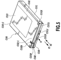
- Fig. 5 is a perspective view of a medium pack in Fig.
1 taken on a front side thereof;
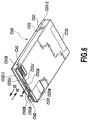
- Fig. 6 is a perspective view of the medium pack in
Fig. 5 taken on a backside thereof;
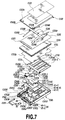
- Fig. 7 is an exploded perspective view of the medium
pack in Fig. 5;
- Fig. 8 is a plan view of a pack main body of the medium
pack in Fig. 5;
- Fig. 9A is a plan view of major parts for explaining
an uncoupled state of a holder and a joint of the medium
pack in Fig. 5, while Fig. 9B is a plan view of the major
parts for explaining a coupled state of the holder and the
joint;
- Fig. 10A is a sectional view of major parts for
explaining an unconnected state of the holder and an ink
pack of the medium pack in Fig. 5, while Fig. 10B is a
sectional view of the major parts for explaining a
connected state of the same;
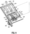
- Fig. 11 is a perspective view of major parts for
explaining an attached state of the medium pack in Fig.
5;
- Fig. 12 is a perspective view of major parts for
explaining states before and after the medium pack in Fig.
5 is attached;
- Fig. 13 is a plan view of major parts for explaining
states before and after the medium pack in Fig. 5 is
attached;
- Fig. 14 is a plan view of major parts for explaining
a state in which the medium pack in Fig. 5 is attached;
- Fig. 15 is a plan view of major parts for explaining
a discharge passage for waste ink formed when the medium
pack in Fig. 5 is attached;
- Figs. 16A and 16B illustrate a forward end section
of the medium pack when the medium pack is attached to a
printer main body; Fig. 16A being a front view for
explaining an example of a configuration of an opening for
transporting a printing medium in the medium pack in Fig.
5, while Fig. 16B being a sectional view taken along the
line XVIB-XVIB in Fig. 16A;
- Figs. 17A and 17B illustrate the forward end section
of the medium pack when the medium pack is not attached
to the printer main body; Fig. 17A being a front view for
explaining an example of another configuration of the
opening for transporting a printing medium of the medium
pack in Fig. 5, while Fig. 17B being a sectional view taken
along the line XVIIB-XVIIB in Fig. 17A;
- Fig. 18 is a perspective view of the printer main body
according to an embodiment of the invention;
- Fig. 19 is a perspective view of the printer main body
with a part of a chassis thereof omitted;
- Fig. 20 is a sectional view of the printer main body
taken from a side thereof;
- Fig. 21 is a perspective view of the printer main body
and, in particular, a state of a mechanism for feeding paper
at a portion to be connected with the medium pack after
the pack is attached;
- Fig. 22 is a perspective view of a state of the
mechanism for feeding paper before the pack is attached;
- Fig. 23 is an illustration of the mechanism for feeding
paper showing, in particular, an operating position of an
ASF trigger;
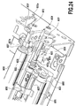
- Fig. 24 is an illustration of the mechanism for feeding
paper showing, in particular, another operating position
of the ASF trigger;
- Fig. 25 is an illustration of the mechanism for feeding
paper showing initial positions of a pick-up roller and
a press plate;
- Fig. 26 is an illustration of the mechanism for feeding
paper showing standby positions of the pick-up roller and
the press plate;
- Fig. 27 is an illustration of the mechanism for feeding
paper showing a state in which printing media are
sandwiched between the pick-up roller and the press plate;
- Figs. 28A, 28B and 28C are illustrations of the
mechanism for feeding paper showing an operation of feeding
printing media piled up in the pack one by one with the
pick-up roller and the press plate;
- Fig. 29 is an illustration of the printer main body
showing, in particular, a joint member which is connected
with a carriage to replenish ink chambers on the carriage
with ink;
- Fig. 30 is a perspective view showing a state before
ink supplying needles of the carriage are inserted into
the joint member;
- Fig. 31 is a plan view in the sate shown in Fig. 30;
- Fig. 32 illustrates a state in which the carriage has
further moved from the states shown in Figs. 30 and 31 to
insert the ink supplying needles of the carriage;
- Fig. 33 illustrates a state in which the carriage has
further moved from the state shown in Fig. 32 to put an
air suction hole in contact with an air suction cap of the
joint member;
- Fig. 34 illustrates a construction for disconnecting
the carriage after the carriage and the joint member are
connected;
- Figs. 35A, 35B and 35C are illustrations for
explaining the construction for disconnecting the
carriage showing, in particular, an operation of a removing
lever;
- Fig. 36 is a perspective view of the printer main body
showing, in particular, a structure associated with an
encoder sensor integrally attached to the carriage;
- Fig. 37 illustrates a light-emitting element and a
light-receiving element of the encoder sensor;
- Fig. 38 illustrates a relationship between a flexible
substrate connected to the carriage and the encoder and
an encoder scale;
- Fig. 39 is a vertical sectional view showing a
structure of a pump used in the printer main body of the
embodiment;
- Figs. 40A and 40B are illustrations for explaining
an operation of each of two lead screws used in the printer
main body of the embodiment;
- Fig. 41 is a perspective view of the printer main body
for explaining various operations in accordance with
positions of a pump driving arm and a switching slider which
are moved by one of the two lead screws that is driven by
a pump motor;
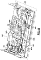
- Fig. 42 is an illustration of the same state as shown
in Fig. 41 with additional elements added;
- Fig. 43 is a perspective view of the printer main body
for explaining various operations in accordance with other
positions of the pump driving arm and the switching slider;
- Figs. 44A, 44B and 44C are illustrations for
explaining a state of an atmosphere communication valve
of the cap in each of the states shown in Figs. 41, 42 and
43;
- Figs. 45A, 45B and 45C are illustrations for
explaining a state of a mechanism for operating the
atmosphere communication valve of the cap in each of the
states shown in Figs. 41, 42 and 43;
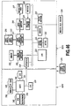
- Fig. 46 is a schematic block diagram of a camera
section and a printer section of the camera in Fig. 1;
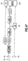
- Fig. 47 is an illustration of signal processing in
the camera section in Fig. 46;
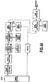
- Fig. 48 is an illustration of signal processing in
the printer section in Fig. 46;
- Fig. 49 is a flow chart showing an example of a
processing procedure when a power supply is turned on in
the construction in Fig. 46; and
- Fig. 50 is a flow chart showing an example of a
processing procedure in a printing mode in the construction
in Fig. 46.
-
-
Embodiments of the printing apparatus according to
the present invention will be described by referring to
the accompanying drawings.
-
In the present specification, "printing" (also
referred to as "recording" in some occasions) means not
only a condition of forming significant information such
as characters and drawings, but also a condition of forming
images, designs, patterns and the like on printing medium
widely or a condition of processing the printing media,
regardless of significance or unmeaning or of being
actualized in such manner that a man can be perceptive
through visual perception.
-
Further, the "printing medium" means not only a paper
used in a conventional printing apparatus but also
everything capable of accepting inks, such as fabrics,
plastic films, metal plates, glasses, ceramics, wood and
leathers, and in the following, will be also represented
by a "sheet" or simply by "paper".
-
Further, in the present specification, a "camera"
indicates an apparatus or device that optically
photographs an image and converts the photographed image
into electrical signals, and in the following explanation,
is also referred to as a "photographing section".
-
Still further, an "ink" (also referred to as "liquid"
in some occasions) should be interpreted in a broad sense
as well as a definition of the above "printing" and thus
the ink, by being applied on the printing media, shall mean
a liquid to be used for forming images, designs, patterns
and the like, processing the printing medium or processing
inks (for example, coagulation or encapsulation of
coloring materials in the inks to be applied to the printing
media).
-
Meantime, one embodiment of a head to which the present
invention is advantageously employed is the embodiment in
which a thermal energy generated by an electrothermal
transducer is utilized to cause a film boiling to the liquid
resulting in a formation of bubbles.
[Basic Structure]
-
Firstly, a basic structure of a device according to
the present invention will be explained in view of Fig.
1 to 4. The device explained in the present embodiment
is constituted as an information processing equipment
comprising a photographing section for optically
photographing an image and then converting the
photographed image into an electric signals (hereinafter,
also referred to as "camera section") and an image
recording section for recording image on the basis of thus
obtained electric signals (hereinafter, also referred to
as "printer section"). Hereinafter, the information
processing equipment in the present embodiment is
explained in the name of a "printer-built-in camera".
-
In a main body A001, there is incorporated a printer
section (recording apparatus section) B100 at the backside
of a camera section A100 in an integral manner. The printer
section B100 records an image by using inks and printing
medium which are supplied from a medium pack (a container
of consumable supplies for a printer) C100. In the present
structure, as apparent from Fig. 4 illustrating the main
body A001 viewing from the backside with an outer package
removed, the medium pack C100 is inserted at the right hand
of the main body A001 in Fig. 4 and the printer section
B100 is arranged at the left hand of the main body A001
in Fig. 4. In the case of performing a recording by the
printer section B100, the main body A001 can be placed
facing a liquid crystal display section A105 up and a lens
A101 down. In this recording position, a recording head
B305 of the printer section B100, which will be described
below, is made to be positioned to eject inks in the
downward direction. The recording position can be made
to be the same position as that of photographing condition
by the camera section A100 and thus is not limited to the
recording position as mentioned above. However, in view
of a stability of a recording operation, the recording
position capable of ejecting the inks in the downward
direction is preferred.
-
There follows the explanations of the basic mechanical
structure according to the present embodiment under the
headings of 1 as "Camera Section", 2 as "Medium Pack" and
-
3 as "Printer Section", and of the basic structure of the
signal processing under the heading of 4 as "Control
System".
1: Camera Section
-
The camera section A100, which basically constitutes
a conventional digital camera, constitutes the
printer-built-in digital camera having an appearance in
Figs. 1 to 3 by being integrally incorporated into the main
body A001 together with a printer section B100 described
below. In Figs. 1 to 3, A101 denotes a lens; A102 denotes
a viewfinder; A102a denotes a window of the viewfinder;
A103 denotes a flush; A104 denotes a shutter release
button; and A105 denotes a liquid crystal display section
(outer display section). The camera section A100, as
described below, performs a processing of data
photographed by CCD, a recording of the images to a compact
flash memory card (CF card) A107, a display of the images
and a transmission of various kinds of data with the printer
section B100. A109 denotes a discharge part for
discharging a printing medium C104 on which the
photographed image is recorded. A108, as shown in Fig.
5, is a battery as a power source for the camera section
A100 and the printer section B100.
2: Medium Pack
-
The medium pack C100 can be attached to and detached
from the main body A001 of the apparatus. In the present
embodiment, the medium pack C100 is attached to the main
body A001 as shown in Fig. 1 by being inserted into an
inserting portion A002 (see Fig. 3) of the main body A001
in the direction indicated by the arrow F1. The inserting
portion A002 is opened when the medium pack C100 is attached
and is closed as shown in Fig. 3 when it is pulled out in
the direction indicated by the arrow F2. The medium pack
C100 is constituted by an ink containing portion, a
printing medium containing portion, a waste ink containing
portion, and so on provided between a pack main body C101
and a cover C102. Fig. 5 is a perspective view of the medium
pack C100 taken from the side of the cover C102 (front
side); Fig. 6 is a perspective view of the medium pack C100
taken from the side of the pack main body C101 (back side);
Fig. 7 is an exploded perspective view of the medium pack
C100; and Fig. 8 is a plan view of the pack main body C101.
-
The medium pack C100 will now be described under
headings 2-1 "Ink Containing Section", 2-2 "Waste ink
Containing section", 2-3 "Printing Medium Containing
Portion", 2-4 "Positions and Configurations of Openings",
2-5 "Other Configurations", 2-6 "Method of Assembly", 2-7
"Ease of Recycling" and 2-8 "Others".
2-1: Ink Containing Section
-
Ink pack containing section S1 for containing ink
packs C130 are formed in the pack main body C101. In the
present embodiment, the ink pack containing section S1 is
formed with three ink pack containing portions S1-Y, S1-M,
and S1-C by partitioning it with ribs C101A and C101B for
containing three ink packs C130-Y, C130-M and C130-C in
which inks in yellow (Y), magenta (M) and cyan (C) are
separately reserved. The ink packs C130-Y, C130-M and
C130-C may be integrally formed, and partitions to be
described later are not required in this case. When the
ink packs C130-Y, C130-M and C130-C are formed as separate
bodies, they are positioned in the ink pack containing
portions S1-Y, S1-M and S1-C by the ribs C101A and C101B
such that they are not misaligned with each other.
-
The ink packs C130 (ink packs C130-Y, C130-M and
C130-C) are held by an ink pack holder C131. In the present
embodiment, the ink packs C130 are formed like bags using
films having a capability of recovering from pin holes in
order to seal inks therein, as shown in Figs. 10A and 10B.
As shown in these figures, an outer surface of a folded
portion C130A of the same is bonded or welded to a curved
surface C131A of the holder 131. The curved surface C131A
guides the folded portions C130A of the ink packs C130 such
that they are not flattened to maintain them in a curved
form. Each of the ink packs C130 is formed like a bag by
folding a sheet material at the portion 130A and then by
sealing it at three sides thereof through bonding or
welding, excepting the folded portions 130A. The holder
C131 is formed with openings C131B where the folded
portions C130A of the ink packs C130 are exposed on the
left side of the holder as shown in Figs. 10A and 10B.
Further, the holder C131 is formed with coupling latches
C131C, C131C to allow it to be coupled with an ink pack
joint C132 to be described later. Regarding the positions
where the coupling latches C131C, C131C are formed, they
may be formed in positions in the right and left sides the
holder C131 close to the center of the same as shown in
Figs. 7, 10A and 10B, and they may alternatively be formed
in positions in the right and left sides of the holder C131
close to the ends of the same as shown in Figs. 9A and 9B.
Thus, the holder C131 holding the ink pack C130 is
positioned in a containing section S2 of the pack main body
C101 (see Fig. 7).
-
Denoted C132 is an ink pack joint having a
substantially T-shaped planar configuration which is
contained in the pack main body C101 such that it can slide
in the direction indicated by the arrow F2. Specifically,
one end C132-1 of the joint C132 and another end C132-2
of the same are contained in containing sections S3 and
S4 of the pack main body C101 such that they can slide in
the directions indicated by the arrows F1 and F2,
respectively. A containing section S5 for containing a
waste ink absorption body to be described later is formed
under a central portion C132-3 of the joint C132. Three
hollow needles C133 are provided at the end C132-1 in an
opposing relationship with the three openings C131B of the
holder C131. The needles C133 communicate with ink supply
ports P1, P2 and P3 at the end C132-2 through ink passages
L1, L2 and L3. A waste ink introduction port P4 formed
at the end C132-2 communicates with a waste ink discharge
port P5 formed on a side of the central portion C132-3
through an ink passage L4. A rubber plug C134 is fitted
in each of the ports P1, P2, P3 and P4 to allow insertion
and removal of needles B502C, B502M, B502Y and B503 of the
apparatus main body A001 to be described later. When the
medium pack C100 is attached to the apparatus main body
A001, the needles B502C, B502M, B502Y and B503 enter the
pack main body C101 through an opening C101H formed on the
pack main body C101. When the needles B502C, B502M, B502Y,
and B503 are removed, elastic restoring properties of the
rubber plugs C134 automatically close the holes formed by
the B502C, B502M, B502Y and B503. In the case that the
joint C132 is provided with a structure in which a plurality
of members located in upper and lower positions in Fig.
7 are assembled with each other, grooves extending along
the ink passages L1, L2, L3 and L4 may be formed on the
lower member and the upper member may be assembled on the
lower member to form the ink passages L1, L2, L3 and L4
inside the joint C132.
-
As will be described later, the coupling latches C131C,
C131C of the holder C131 engage with the joint C132 when
the joint C132 moves in the direction indicated by the arrow
F2 to approach the holder C131. When the coupling latches
C131C, C131C are formed in positions close to the center
of the holder C131 as shown in Figs. 7 and 11, the latches
engage with edges of openings C132A and, when the coupling
latches C131C, C131C are formed in positions close to the
ends of the holder C131 as shown in Figs. 9A and 9B, the
latches engage with both ends of the joint C132.
-
When the medium pack C100 with the ink containing
section having such a construction described above has not
been used or when it has never been attached to the
apparatus main body A001, the joint C132 is in an uncoupled
state in which it is separated from the holder C131 as shown
in Fig. 9A, and the needles C133 on the joint C132 are off
the ink packs C130 as shown in Fig. 10A. When the medium
pack C100 has not been attached yet as thus described, the
ends of the coupling latches C131C, C131C are in contact
with the joint C132 to prevent the joint C132 and the holder
C131 from being coupled. Therefore, the coupling latches
C131C, C131C function as members for interrupting linkage
between the joint C132 and ink packs C130 before the medium
pack C100 is attached.
-
When such an unused medium pack C100 is attached to
the apparatus main body A001 in the direction indicated
by the arrow F1, the needles B502C, B502M, B502Y and B503
on the apparatus main body A001 cause a relative movement
of the joint C132 in the direction indicated by the arrow
F2 while being stuck into the rubber plugs C134 in the ports
P1, P2, P3 and P4, which causes the needles C133 on the
joint C132 to be stuck into the folded portions C130A of
the ink packs C130. When the medium pack C100 is completely
attached as shown in Fig. 9B, the joint C132 is coupled
with the holder C131 by the coupling latches C131C; the
needles B502C, B502M, B502Y and B503 on the apparatus main
body A001 penetrate through the rubber plugs C134 in the
ports P1, P2, P3 and P4 to be in communication with the
ink passages L1, L2, L3 and L4; and the needles C133 on
the joint C132 are put in communication with the interior
of the ink packs C130 as shown in Fig. 10B. After the medium
pack C100 is thus attached, the coupling latches C131C,
C131C function as engaging members for engaging the joint
C132 and ink packs C130 to prevent them from being
decoupled.
-
As a result, the ink packs C130-Y, C130M and C130-C
are connected to ink supply passages to be described later
in the apparatus main body A001 through the ink passages
L1, L2 and L3, which allows inks to be supplied. Since
the ink packs are constituted by films having a capability
of recovering from pin holes, no ink leaks from the regions
pierced by the needles. The waste ink discharge port P5
is connected to a waste ink discharge passage to be
described later in the apparatus main body A001 through
the ink passage L4 to discharge waste ink discharged
through the waste ink discharge passage on to waste ink
absorption bodies C141 to be described later. The waste
ink discharged through the waste ink discharge passage is
a relatively large amount of waste ink that is discharged
into a cap as a result of a suction recovery operation or
a preliminary ejecting operation of a recording head as
will be described later, the waste ink being discharged
using a pump.
-
When the medium pack C100 thus attached is removed
from the apparatus main body A001 in the direction
indicated by the arrow F2, the needles B502C, B502M, B502Y
and B503 on the apparatus main body A001 come out the rubber
plugs C134 in the ports P1, P2, P3 and P4. At this time,
the rubber plugs C134 automatically close the ports P1,
P2, P3 and P4 because of their elastic restoring properties.
The coupling latches C131C keep the holder C131 and joint
C132 in the coupled state, and the needles C133 on the joint
C132 remain inserted in the ink packs C130. That is, the
coupling latches C131C keep the holder C131 and joint C132
in the coupled state after they are once coupled.
-
Thus, the needles C133 on the joint C132 are inserted
into the ink packs C130 only when the medium pack C100 is
first attached to the apparatus main body A001 and are
thereafter kept in the inserted state. In the case of an
unused medium pack C100 which has never been attached to
the apparatus main body A001, the needles C133 on the joint
C132 are not inserted in the ink pack C130, and the ink
packs C130 completely seal inks only by themselves. This
is advantageous in view of the distribution of the medium
pack C100 and the manufacture of the ink packs C130.
-
Specifically, when an unused medium pack C100 is
distributed, since the needles C133 are not inserted in
the ink packs C130, inks can be reliably sealed by the ink
packs C130 alone without being adversely affected by the
ambient temperature such as the temperature during
distribution. Further, since no ink enters the ink
passages L1, L2 and L3 when the medium pack C100 is thus
distributed, it is possible to thoroughly eliminate a
problem that can occur when the ink passages L1, L2 and
L3 are formed of a synthetic resin material, i.e., the
problem of evaporation of ink components through the
synthetic resin material. Further, since inks can be
sealed by the ink packs C130 alone, the ink packs C130 can
be manufactured easily at a low cost by charging inks in
the material of the ink packs C130 while forming it into
bags. Since the needles C133 are stuck in the longitudinal
direction of the ink packs C130 at the folded portions C130A
of the ink packs C130 secured to the holder C131, the
needles C133 can be sufficiently inserted into the ink
packs C130. In this connection, when the needles C133 are
stuck into the ink packs C130 at the top surface or bottom
surface thereof in Figs. 10A and 10B from above and below
in the same figures, it is difficult to maintain a
sufficient amount of insertion of the needles C133 because
the thickness of the ink packs C130 is small in the vertical
direction.
-
Referring to the material to form the ink packs C130,
a material having a multi-layer structure is employed such
that it tightly contacts the circumferential surfaces of
the needles C133 when the needles C133 are inserted as shown
in Fig. 10B to achieve a sufficient sealing effect. A
specific example of such a material is a structure having
four layers constituted by specialty nylon of 27 µm, PVDC
(polyvinylidene chloride) of 3 µm, specialty polyethylene
of 50 µm and normal polyethylene of 20 µm. Another specific
example is a structure having four layers constituted by
specialty nylon of 27 µm, aluminum foil of 7 µm, specialty
polyethylene of 50 µm and normal polyethylene of 20 µm.
Still another example is a material having the same quality
as that of a product named "Cartridge Pack" (trade name)
sold by Daiwa Gravure K.K. into which a dispenser can be
directly inserted. While the aluminum foil layer is used
to prevent evaporation of ink that is contained, the
invention is not limited to aluminum foil layers, and
various types of layers having the effect of preventing
ink evaporation including a layer having aluminum
deposited thereon and a silica-coated layer may be used
as layers having such characteristics.
2-2: Waste Ink Containing Section
-
Waste ink absorption bodies C141 are contained in the
containing section S5. In the present embodiment, two
upper and lower waste ink absorption bodies C141-1 and
C141-2 are contained in an overlapping relationship. The
waste ink absorption bodies C141 (absorption bodies C141-1
and C141-2) are formed with slits C141A in which
positioning projections C101C, C101D and C101E formed on
the pack main body C101 are fitted. The absorption bodies
C141 are also formed with grooves C141B in which a wall
C101F formed on the pack main body C101 is fitted. A gap
C101G is formed as shown in Fig. 11 between a
circumferential wall C101X of the pack main body C101 and
the wall C101F, and the containing section S5 is divided
into a large containing section S5-1 and a small containing
section S5-2 with the gap C101G interposed therebetween.
Therefore, the absorption bodies C141 are divided into a
first absorbing region C141-L which is located on the side
of the large containing section S5-1 and which absorbs a
relatively great amount of waste ink and a second absorbing
region C141-S which is located on the side of the small
containing section S5-2 and which absorbs a relatively
small amount of waste ink, a narrow portion C141C
associated with the gap C101G being interposed between
them.
-
The waste ink discharge port P5 faces the large
containing section S5-1 as shown in Fig. 11. Therefore,
a relatively great amount of waste ink discharged from the
waste ink discharge port P5 is reliably absorbed and held
by the first absorbing regions C141-L of the absorption
bodies C141. When the holder C131 and joint C132 are
coupled by the coupling latches C131C, the waste ink
discharge port P5 is positioned substantially in the middle
of the large containing section S5-1 or substantially in
the middle of the first absorbing regions C141-L of the
absorption bodies C141, as shown in Fig. 11. As a result,
the first absorbing regions C141-L efficiently and
reliably absorb and hold a relatively great amount of waste
ink.
-
The small containing section S5-2 communicates with
the opening C101H formed on the pack main body C101. When
the medium pack C100 is inserted in the apparatus main body
A001 in the direction indicated by the arrow F1, an ink
absorption body B506 at the apparatus main body A001 to
be described later enters the small containing section S5-2
through the opening C101H to be inserted into the second
absorbing regions C141-S of the absorption bodies C141.
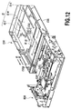
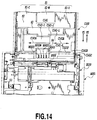
Figs. 12 to 15 are illustrations for primarily explaining
the positional relationship between the ink absorption
body B506 and the absorption bodies C141. The joint C132
in the pack main body C101 is omitted in those figures,
and Fig. 15 further omits the pack main body C101. When
the medium pack C100 is inserted in the apparatus main body
A001, the ink absorption body B506 is inserted in the second
absorbing regions C141-S of the absorption bodies C141 as
shown in Fig. 15.
-
As will be detailed later, ink ejected from the
recording head to positions out of a printing medium C150
are introduced to the ink absorption body B506 of the
apparatus main body A001 due to capillarity. The amount
of the ink ejected to positions out of the printing medium
C150 is relatively small, and the relatively small amount
of ink is introduced to the ink absorption body B506 as
waste ink. The waste ink introduced to the ink absorption
body B506 is absorbed and held by the second absorbing
regions C141-S due to capillarity when the ink absorption
body B506 is inserted in the second absorbing regions
C141-S of the absorption bodies C141 at the medium pack
C100. Thus, the relatively small amount of waste ink
introduced to the ink absorption body B506 is absorbed and
held by the second absorbing regions C141-S of the
absorption bodies C141.
-
The ink absorption body B506 is formed of a relatively
hard porous material, and the absorption bodies C141 are
formed of a relatively soft porous material. Therefore,
when they are put in contact, only the contacting parts
of the absorption bodies C141 at the medium pack C100 as
a consumable supply are greatly deformed, and there is
small deterioration of the ink absorption body B506 at the
apparatus main body A001. As a result, when the medium
pack C100 as a consumable supply is repeatedly attached
to the apparatus main body A001 many times, a good state
of connection can be always maintained between the ink
absorption body B506 and the absorption bodies C141.
Further, such compression and deformation of the
contacting parts of the absorption bodies C141 results in
a proper capillary force which allows ink to come out the
ink absorption body B506 in a favorable manner.
-
It is advantageous to divide the absorption bodies
C141 into the first absorbing region C141-L and the second
absorbing region C141-S with the wall C141B in preventing
waste ink from leaking out from an opening C101J.
Specifically, when waste ink in the entire absorption
bodies C141 starts concentrating and moving toward the
opening C101J, the waste ink is hindered by the wall C101F
from moving and is forced to detour the wall C101F. By
causing the waste ink to thus detour the wall C101F, it
is possible to avoid a concentrative movement of the waste
ink in the entire absorption bodies C141 toward the opening
C101J, thereby preventing the waste ink from leaking out
from the opening C101J. In the present embodiment, since
a relatively great amount of waste ink is absorbed and held
by the first absorbing region C141-L, it is possible to
effectively prevent the concentrative movement of the
relatively great amount of waste ink toward the opening
C101J. Further, since the second absorbing region C141-S
absorbs and holds only a small amount of waste ink
introduced from the ink absorption body B506 at the
apparatus main body A001 by a capillary force, the waste
ink can be prevented from leaking out in the vicinity of
the opening C101J to reliably hold the same.
2-3: Printing Medium Containing Portion
-
As shown in Fig. 7, a medium slide sheet C151 for
covering the containing sections S1, S2, S3, S4 and S5 from
above is fitted and positioned in the pack main body C101.
Printing media C150 are stored on the slide sheet C151.
Specifically, a plurality of (e.g., 20) printing media C150
in the form of sheets are placed on the slide sheet C151,
and a medium press sheet C152 is further placed on the same.
A relatively hard medium press plate C153 is attached to
the press sheet C152. A medium positioning spring C154
is elastically interposed between the press sheet C152 and
the cover C102. The spring C154 is attached to the pack
main body C101 by elastically engaging both ends C154A and
C154B thereof with the circumferential wall C101X of the
pack main body C101 in predetermined positions in the plane
of the wall. Legs C154C, C154D, C154E and C154F of the
spring C154 urge the press sheet C152 downward as viewed
in Fig. 7. A claw C102A which can be elastically engaged
with a hole C101K on the circumferential wall C101X of the
pack main body C101 is formed at one end C102-1 of the cover
C102. Another end C102-2 of the cover C102 is attached
to the pack main body C101 with a seal C103 as shown in
Figs. 5 and 6.
-
On the circumferential wall C101X of the pack main
body C101, there is formed an opening C101L for
transporting the printing media C150 stored on the slide
sheet C151 one by one in the direction indicated by the
arrow A (see Fig. 5). The printing medium C150 is ejected
by a pick-up roller B201 and a press plate 202 at the
apparatus main body A001 as will be described later. When
the medium pack C100 is attached to the apparatus main body
A001, the pick-up roller B201 can enter the pack main body
C101 through an opening C101M formed on the pack main body
C101 to be pressed against the lowermost one of the printing
media C150 piled up on the slide sheet C151 through a
cut-out C151A on the slide sheet C151. As shown in Figs.
5, 6 and 7, a shutter C155 is mounted at the opening C101M
such that it can be opened and closed in the directions
indicated by the arrows F1 and F2, and the shutter C155
is always urged by a spring C156 in the closing direction
indicated by the arrow F1. The shutter C155 normally
closes the opening C101M as shown in Fig. 6 and, when the
medium pack C100 is attached to the apparatus main body
A001, it is opened in the direction indicated by the arrow
F2 to allow the pick-up roller B201 to enter. When the
medium pack C100 is attached to the apparatus main body
A001, the press plate B202 can enter the pack main body
C101 through cut-outs C101N and C102B formed on the pack
main body C101 and the cover C102 to be pressed against
the press plate C153 of the press sheet C152.
-
Thus, by attaching the medium pack C100 to the
apparatus main body A001, the printing media C150 in the
medium pack C100 are set in a standby position in which
they can be sandwiched between the pick-up roller B201 and
the press plate 202. When an ASF trigger to be described
later is released in this state, the printing media are
sandwiched by those members, and the pick-up roller B201
rotates in a predetermined transport direction to
transport the lowermost one of the printing media C150 on
the slide sheet C151 in the direction indicated by the arrow
A through the opening C101L. At this time, since the
lowermost printing medium C150 slides on the slide sheet
C151 to be transported, the printing medium C150 can be
smoothly transported by making the top surface of the slide
sheet C151 smoother for the printing medium C150. The
slide sheet C151 preferably has properties that allow the
printing medium C150 to be transported favorably as
described above. Specifically, this may be achieved by
forming the sheet using a material having a low friction
coefficient or by processing the sheet such that it has
a low friction coefficient on a surface thereof in contact
with the printing medium C150. Referring to examples of
such processing, measures such as a fluorinating process
or an embossing process on the sheet may be taken. In order
to improve transportability, it is advantageous to take
a measure against static electricity that can occur between
the slide sheet C151 and the printing medium C150.
-
Since the opening constituted by the cut-outs C101N
and C102B and the opening C101M are formed in positions
in an opposing relationship with each other, the printing
media C150 can be sandwiched between the pick-up roller
B201 and the press plate B202. By sandwiching the printing
media C150 between the pick-up roller B201 and the press
plate 202, an optimum transporting force can be imparted
from the pick-up roller B201 to the printing media C150
to transport the printing media C150 with reliability. In
the present embodiment, since the press plate B202 is
smaller than the pick-up roller B201 as will be described
later, the opening constituted by the cut-outs C101N and
C102B is formed smaller than the opening C101M. By forming
the opening constituted by the cut-outs C101N and C102B
with such a small size, the rigidity of the medium pack
C100 is improved accordingly. In the present embodiment,
since the shutter C155 is provided at the relatively large
opening C101M to always close the opening C101M when the
medium pack C100 is not attached to the apparatus main body
A001, it is possible to prevent foreign substances from
entering through the relatively large opening C101M.
-
Since the spring C154 urges the printing media C150
through the press sheet C152, all parts of the lowermost
one of the printing media C150 is properly pressed against
the slide sheet C151. Since the press plate B202 is pressed
against the relatively hard press plate C153, the forward
ends of the printing media C150 located close to the opening
C101L is pressed relatively stronger to improve the
reliability of the operation of transporting the printing
medium C150. The leg C154C of the spring C154 that is
formed in a relatively large size gives a relatively
stronger press on a part of the press sheet C152 opposite
to the part pressed by the press plate 202 with its
relatively great urging force. As a result, the forward
ends of the printing media C150 located close to the opening
C101L is more uniformly pressed to perform the operation
of transporting the printing media C150 with higher
reliability. Thus, the printing media C150 are sandwiched
between the slide sheet C151 and the press sheet C152 and
are transported one by one starting with the lowermost one.
-
Since the slide sheet C151 covers the containing
sections S1, S2, S3, S4 and S5 from above in the medium
pack C100, the risk of contact between ink and the printing
media C150 is avoided. In particular, by covering the
containing section S5, contact between any waste ink in
the same and the printing media C150 is avoided. Since
waste ink which has leaked out from the containing section
S5 must flow by way of the outer periphery of the slide
sheet C151 to contact the printing media C150, any contact
between the waste ink and the printing media C150 is
consequently avoided. Volatile components of waste ink
generated at the containing section S5 exhaust from the
outer periphery of the slide sheet C151 through the mating
surface between the pack main body C101 and the cover C102,
for example. Thus, the slide sheet C151 not only serves
the function of maintaining slidability of the printing
media C150 but also functions as a cover for the waste ink
containing section S5.
2-4: Positions and Configurations of Openings
-
Since the medium pack C100 is formed with the two
openings C101H and C101J, waste ink from two waste ink
passages in the apparatus main body A001 can be efficiently
collected into the medium pack C100 as described above.
Specifically, a relatively large amount of waste ink
discharged as a result of a suction recovery process and
a preliminary ejecting process of the recording head is
discharged by a pump in the apparatus main body A001 to
the first absorbing regions C141-L of the absorption bodies
C141 having a relatively large capacity through the needles
B502C, B502M, B502Y and B503 and the joint C132 extending
into the opening C101H, the waste ink being reliably
absorbed and held by the first absorbing regions C141-L.
A relatively small amount of waste ink ejected to
positions out of the printing medium C150 is absorbed and
held by the second absorbing regions C141-S of the
absorption bodies C141 having a relatively small capacity
through the absorption body B506 extending into the opening
C101J due to capillarity.
-
Since the openings C101H and C101J are formed on the
forward end of the medium pack C100, the two waste ink
passages in the apparatus main body A001 are connected to
the medium pack C100 only by inserting the medium pack C100
into the apparatus main body A001 in the direction
indicated by the arrow F1.
-
The opening C101M into which the pick-up roller B201
enters and the opening C101J for collecting waste ink are
formed in positions away from each other with the opening
C101H interposed between them. This makes it possible to
prevent waste ink from flowing from the opening C101J to
the opening C101M, thereby preventing the waste ink from
smearing the printing media C150 located in the vicinity
of the opening C101M.
-
Since the joint C132 located inside the opening C101H
is formed with the ink supply ports P1, P2 and P3 and the
waste ink introduction port P4 and, in addition, the ink
passages L1, L2, L3 and L4 in communication with them, each
of the four ink passages L1, L2, L3 and L4 are reliably
connected to the apparatus main body 001 with the single
joint C132. Inside the opening C101H, the ports P1, P2,
P3 and P4 are arranged in this order in the direction of
departing from the opening C101M. That is, the waste ink
introduction port P4 is further from the opening C101M than
the ink supply ports P1, P2 and P3 are. Therefore, in the
event that waste ink should be deposited in the waste ink
introduction port P4, it is possible to prevent the waste
ink from flowing up to the opening C101M, thereby
preventing the waste ink from smearing the printing media
C150 located in the vicinity of the opening C101M.
2-5: Other Configurations
-
The medium pack C100 is equipped with an EEPROM to
be described later, for storing identification data such
as the types and remaining quantities of the ink contained
in the medium pack C100 and the printing media C150. In
the present embodiment, the EEPROM is provided in the pack
main body C101 that is located at the bottom of the
containing section S5-2. A connector C161 for the EEPROM
is provided on the bottom of the pack main body C101 in
the vicinity of the opening C101J for collecting waste ink,
as shown in Fig. 6. When the medium pack C101 is attached
to the apparatus main body A001, the connector C161 is
connected to a connector on the apparatus main body A001
which is not shown.
-
The connector C161 can be used to detect leakage of
waste ink because it is located in the vicinity of the
opening C101J for collecting waste ink. Specifically, in
the event that waste ink which has leaked out from the
opening C101J should flow up to the position of the
connector C161 to cause a connection failure between the
connector C161 and the connector at the apparatus main body
A001, the leakage of waste ink is detected by detecting
the connection failure. For example, it is possible to
detect a connection failure because of the presence of
waste ink between contacts of the connector C161 and the
connector at the apparatus main body A001, an electrical
short-circuit caused by waste ink deposited between a
plurality of contacts of the connector C161 or an
electrical short-circuit caused by waste ink deposited
between a plurality of contacts of the connector at the
apparatus main body A001, and the leakage of waste ink can
be detected based on the result of the detection.
-
At the opening C101L for transporting the printing
medium, there may be provided a gate portion C162 which
disallows two or more printing media C150 to pass
simultaneously and allows them to pass one by one. The
gate portion C162 limits the width of the opening C101 to
a size corresponding to the thickness of one printing
medium C150. Such a gate portion C162 may be provided such
that it covers the entire opening C101L in the longitudinal
direction thereof or such that it covers part(s) of the
opening, e.g., a central part in the longitudinal direction
thereof or parts on both sides thereof. In the present
embodiment, since the pack main body C101 having the
opening C101L is obtained by injection-molding a resin
material, it is strongly desired to limit the width of the
opening C101L accurately while taking into account a strain
of the resin material, etc.
-
Figs. 16A and 16B and Figs. 17A and 17B illustrate
an example of a configuration for accurately limiting the
width of the opening C101L of the pack main body C101 that
is obtained by injection-molding a resin material as thus
described. Those figures schematically show only the
forward end section of the pack main body C101. Figs. 16A
and 16B illustrate the forward end section when the medium
pack C100 is attached to the apparatus main body A001, while
Figs. 17A and 17B illustrate the forward end section when
the medium pack C100 is not attached to the apparatus main
body A001.
-
In those figures, denoted C162 is a gate portion which
is formed integrally with an upper edge part of the opening
C101L in the middle thereof and which limits the width W
of the opening C101L to a size to allow only one printing
medium C150 to pass. In the present embodiment, the gate
portion C162 is formed with a slight leftward shift from
the center of the opening C101L such that it is located
close to a transporting datum of the printing medium which
is formed on the left-hand side of Fig. 16A, taking into
account of the use of various sizes of printing media.
Guide holes C163A and C163B and a slit C164 are formed on
the pack main body C101. When the medium pack C100 is
attached to the apparatus main body A001 in the direction
indicated by the arrow F1, guide pins GP1 and GP2 located
at the apparatus main body A001 enter the guide holes C163A
and C163B in a relative manner, as shown in Fig. 16B.
Therefore, the interval between the guide holes C163A and
C163B is forcibly equalized to the interval between the
guide pins GP1 and GP2 with the pack main body C100 deformed
elastically. Consequently, the gate portion C162
accurately limits the width W of the opening C101L to a
size to allow one printing medium C150 to pass. The slit
C164 facilitates deformation of the pack main body C100
and absorbs the amount of deformation. At least the part
of the pack main body C100 where the opening C101L is formed
may be a panel obtained by injection-molding a resin
material.
-
In this example, the gate portion C162 closes the
opening C101L as shown in Figs. 17A and 17B to disallow
a printing medium C150 to pass when the medium pack C100
is not attached to the apparatus main body A001.
-
Thus, the gate portion C162 in this example not only
has a gate function to limit the width of the opening C101L
to a size to allow one printing medium C150 to pass but
also functions as a stopper for preventing the printing
media C150 from coming out the medium pack C100
accidentally. The later stopper function may be provided
by a gate portion which is separate from the gate portion
C162. In this case, the gate portion may close the opening
C101L when the medium pack C100 is not attached to the
apparatus main body A001 and may expand the width of the
opening C101L to at least a size to allow one printing
medium C150 to pass by being displaced by guide pins at
the apparatus main body A001 when the medium pack C100 is
attached to the apparatus main body A001.
-
While projections as guide pins are provided on the
apparatus main body and guide holes as recesses are
provided on the medium pack in the examples in Figs. 16A,
16B, 17A and 17B, such engaging members may have any
configuration as long as they can expand the gap at the
opening C101L when engaged. For example, a recess may be
provided on the apparatus main body, and a projection that
is displaced under the guidance of the recess may be
provided on the medium pack.
2-6: Method of Assembly
-
To assemble the medium pack C100, the absorption
bodies C141 and the joint C132 are sequentially put in the
pack main body C101 from above. The joint C132 is placed
in a position where it is not coupled with the holder C131
as shown in Fig. 9A. Almost simultaneously, the
combination of the ink packs C130 and the holder C131 (see
Fig. 7) is put in the pack main body C101 from above.
Thereafter, the slide sheet C151, a predetermined quantity
of printing media C150, the press sheet C152 and the
positioning spring C154 are sequentially put in the pack
main body C101 from above. Then, the cover C102 is fitted
to the opening at the top of the pack main body C101, and
the claw C102A is engaged with the hole C101K. The claw
C102A is temporarily elastically deformed by pressing the
cover C102 downward and is elastically restored in a
position where it faces the hole C101K to be engaged with
the hole C101K. Thereafter, the seal C103 is applied
between the cover C102 and the pack main body C101. Thus,
elements to be contained in the pack main body C101 can
be sequentially put in the pack main body C101 from above
with favorable operability and, similarly, the cover C102
can be easily attached from above.
-
Components such as the shutter C155, the spring C156,
the connector C161 and the EEPROM are attached to the pack
main body C101 before at least the cover C102 is attached.
2-7: Ease of Recycling
-
When a medium pack C100 is used until the printing
media C150 or ink as consumable supplies therein run out,
the used medium pack C100 can be collected and recycled.
-
First, the cover C102 is removed from the used medium
pack C100 thus collected. Since the cover C102 is not
directly welded or bonded to the pack main body C101, it
can be easily removed upward from the pack main body C101
by peeling off the seal C103 and disengaging the claw C102A
and the hole C101K. Thereafter, the elements in the pack
main body C101 can be sequentially removed upward in an
order that is the reverse of the order of assembly of the
medium pack C100 described above. In doing so, the holder
C131 and the joint C132 may be disengaged after taking them
out upward in the coupled state as shown in Fig. 9B.
-
Then, the medium pack C100 is assembled in the order
described above after replacing the absorption bodies C141
and the ink pack C130 with new ones, replenishing the
printing media C150 or replacing components such as the
holder C131 and joint C132 with new ones, as occasions
demand. At this time, sufficient mounting strength of the
cover C102 can be maintained by replacing the seal C103
with a new one.
-
The elements in the pack main body C101 are not welded
to the pack main body C101, and this is advantageous in
improving the operability of assembly of the medium pack
and the ease of recycling of the same and in facilitating
the evaporation of ink absorbed by the absorption bodies
C141 to maintain the waste ink absorbing function of the
absorption bodies C141. Since volatile components in
waste ink are guided by the slide sheet C151 to the
circumferential wall C101X of the pack main body C101 to
be exhausted, it is possible to prevent the printing media
C150 from being adversely affected by the same.
2-8: Others
-
When a medium pack C100 is used until the ink therein
as a consumable supply runs out or nearly runs out, the
ink can be replenished without disassembling the medium
pack C100. Specifically, there is prepared an ink
replenisher in the form of an injector capable of injecting
ink reserved therein from the tip of an injection needle.
The tip of the injection needle is stuck into the rubber
plugs 134 in the ink supply ports P1, P2 or P3 through the
opening C101K of the medium pack C100 to inject the ink
into the ink pack C130-C, C130-M or C130-Y through the ink
passage L1, L2 or L3 from the ink replenisher. By preparing
ink replenishers containing inks in cyan (C), yellow (Y)
and magenta (M) separately, the inks in the ink packs C130-C,
C130-M and C130-Y can be selectively replenished.
-
The ink packs C130-C, C130-M and C130-Y can be directly
replenished with inks by sticking the tips of the injection
needles of the ink replenishers described above into the
ink packs C130-C, C130-M and C130-Y after disassembling
the medium pack C100. In this case, the holes formed in
the ink packs C130-C, C130-M and C130-Y when they are stuck
with the injection needles must be closed after the
injection needles are pulled out. For example, possible
approaches to this problem are to use a material having
a property of automatically closing such holes to mold the
ink pack C130-C, C130-M and C130-Y and to close such holes
using seals, valves and the like.
3: Printer Section
-
In the present embodiment, a so-called serial type
printer section (or printer main body) B100 is employed
in which inkjet type recording heads are used and in which
a photographed image or the like is printed on a printing
medium by repeatedly scanning the recording heads on the
printing medium and then transporting the printing medium
in a direction substantially orthogonal to the scanning
direction a predetermined distance.
-
In the printer main body of the present embodiment,
ink supply from the ink packs in a medium pack C100 attached
thereto to the recording heads mounted on the carriage is
performed using a method in which the ink supply passages
and the recording heads are in an unconnected state at least
during recording and in which an ink supply enabled state
is established to supply inks by connecting the ink supply
passages and the recording heads at appropriate timing
(hereinafter referred to as "pit-in method for
convenience). That is, a sub-tank for reserving a very
small amount of ink is mounted on the carriage. When the
carriage moves to reach an ink supplying position, a supply
passage is formed between the sub-tank and an ink pack in
the medium pack C100 through a joint portion provided in
the ink supplying position, whereby ink is supplied into
the sub-tank. A pump is also provided to introduce the
ink from the ink pack by generating a negative pressure
in the sub-tank when the ink is supplied to the sub-tank.
-
Fig. 18 is a perspective view of the printer main body
B100 taken from the side of a medium pack C100 attaching
section of the same, and Fig. 19 is a perspective view of
the main body taken from the side opposite to the attaching
section. Fig. 19 omits a top surface of a chassis serving
as a structural member, the carriage and a mechanism for
moving the same, a roller for transporting the printing
medium, and so on. Fig. 20 is a lateral sectional view
of the main body B100 with the medium pack attaching section
located on the left side.
-
As shown in those figures, the printer main body B100
has a thin configuration which is a substantially
rectangular and which is shorter in height than its
lengthwise and breadthwise dimensions. A chassis B101
constitutes a structural member of the printer main body
B100 and defines the outline of the rectangle.
Specifically, the chassis B101 is assembled such that it
covers substantially all of the six sides forming the
rectangle except for the two sides shown in Fig. 18. The
opening surrounded by sides of the rectangle in the
directions of the breadth and height thereof shown in Fig.
18 is an opening for attaching the medium pack C100. The
relatively large plane surrounded by lengthwise and
breadthwise sides similarly shown in Fig. 18 is covered
by the chassis B101 in a part thereof, and the uncovered
part has a width substantially equal to the width of a
carriage B301 mounted with the recording head and extends
over a moving range of the carriage B301.
-
Elements that make up the printer main body B100 are
fixed or rotatably supported by the chassis B101 to form
mechanisms in the printer main body. Specifically, the
printer main body B100 of the present embodiment generally
has a paper-feed and transport mechanism, a carriage moving
mechanism, an ink supply and recovery mechanism and a pack
connection mechanism located in the rectangle formed by
the chassis B101.
-
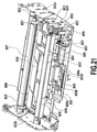
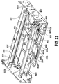
Referring to the paper-feed and transport mechanism,
as apparent from a schematic general construction shown
in Fig. 20, a pick-up roller B201 and a press plate B202
for pressing printing medium against the roller with an
adequate pressure are disposed at the left end in the figure
where the medium pack C100 is attached. The pick-up roller
B201 is configured to be able to rotate in a predetermined
angular range by being rotatably supported by roller arms
B203 which are in turn rotatably supported by an ASF
connecting shaft B204. Similarly, the press plate B202
is also rotatably configured, which allows the roller B201
and the press plate B202 to enter the attached medium pack
C100 to thereby sandwich the printing media directly
(strictly speaking, the press sheet C152 intervenes
between the press plate and the media). As will be
described later, the pick-up roller B201 is rotated by a
driving force of an LF motor (not shown) transmitted
through a PF roller B205 to be described later, the roller
arms B203 and a gear train provided on the ASF connecting
shaft B204, while the printing media are pressed by the
press plate B202 against the roller with an adequate
pressing force to pick up the printing media one by one
and feed the printing medium into the printer main body
B100.
-
As shown in Fig. 18, the pick-up roller B201 has a
longitudinal length that is smaller than the width of the
printing media in the medium pack C100 (see Fig. 7), and
it is provided in the vicinity of an end of the opening
for attaching the medium pack C100. The width of the press
plate B202 is smaller than the width of the pick-up roller
B201 although not shown in Fig. 18, and it therefore presses
the printing media against only a part of the pick-up roller
B201. Thus, the paper feed mechanism of this printer
engages with only a part of a printing medium to be fed
to feed the same.
-
As further paper-feed and transport mechanisms, as
shown in Fig. 20, a combination of a PF roller B205 and
a pinch roller B206 and a combination of a PF roller B207
and a pinch roller B208 are provided in respective
positions sandwiching a moving range of the carriage B301
(the moving direction of which is in the direction
perpendicular to the plane of the figure) downstream of
the pick-up roller B201 and so on (on the right of the same
in the figure) in the paper feed direction. The PF rollers
B205 and B207 are driven for rotation by an LF motor which
is provided in a position that is in a substantially
diagonal relationship with the part of the printer main
body where the paper feed mechanism including the pick-up
roller is provided and a gear train which is provided on
a lateral surface of the chassis at the end of the chassis
that is opposite to the end where the paper feed mechanism
is provided with respect to the opening, for transmitting
the driving force of the LF motor. Thus, in association
with a scan of the recording head mounted on the carriage
B301, a printing medium is transported a predetermined
amount by the combination of the PF roller B205 and the
pinch roller B206 and the combination of the PF roller B207
and the pinch roller B208 respectively provided upstream
and downstream sides of the moving range of the carriage
B301 in the transporting direction of the printing medium.
When this operation is repeated to complete printing, the
paper is ejected out of the printer main body B100 or out
of the apparatus main body A001 of the camera. In the
printing medium transport passage, as shown in Figs. 18
and 20, a platen B306 is disposed under the moving range
of the carriage B301. As a result, a printing medium under
transportation is slidingly supported by the platen B306
on its surface opposite to a surface to be printed, and
this ensures the flatness of the printing medium.
-
While the PF roller B205 on the upstream side and the
above-mentioned press plate B202 are supported by the same
shaft, the press plate B202 is rotated using a frictional
force of an arm spring as will be described later in order
to adjust the pressing force adequately. The roller arm
B203 supporting the pick-up roller B201 is similarly
rotated using a frictional force of a roller spring (not
shown) according to the rotation of an ASF connecting shaft
(not shown) supporting the same, which makes it possible
to apply an adequate pressing force to the printing medium
or paper similarly to the press plate during the paper is
fed.
-
The carriage moving mechanism is a mechanism for
driving a lead screw B302 and the like shown in Figs. 18
to move the carriage B301.
-
The lead screw B302 is provided such that it extends
along the entire breadthwise sides of the rectangle
constituting the printer main body or in the longitudinal
direction of the main body, while a guide shaft B303 for
the carriage B301 (see Fig. 20) is similarly provided in
parallel with the lead screw B302. A carriage motor (or
CR motor which is not shown) for generating a driving force
for rotating the lead screw B302 is provided on the
downstream side of the printing medium transportation that
is the right side of Fig. 20.
-
The carriage B301 can be moved along the guide shaft
B303 when a screw pin (not shown) provided thereon engages
with a spiral groove formed on the circumference of the
lead screw B302 and the lead screw B302 is rotated by the
driving force of the carriage motor.
-
The carriage B301 is provided with ink chambers B304Y,
B304M and B304C as the sub-tanks for respective types of
ink, i.e., yellow (Y), magenta (M) and cyan (C) used for
printing. As described above, each of the ink chambers
has a capacity with which a very small amount of ink only
sufficient to print one printing medium can be contained.
It is therefore necessary to replenish the inks from the
ink packs of the medium pack C100 at predetermined
intervals. Recording heads B305Y, B305M and B305C
associated with the respective types of ink are provided
under those ink chambers. The recording heads are
arranged in a scanning direction thereof, that is, the
direction perpendicular to the plane of Fig. 20, and a
plurality of ink ejecting ports (hereinafter also called
nozzles) are disposed on each of the recording heads in
a direction substantially orthogonal to the scanning
direction. In each of the recording heads, a liquid
passage is formed in communication with each of the nozzles,
and an electrothermal transducer and electrode wiring and
the like for supplying an electrical signal to the same
are provided corresponding to the liquid passage. As a
result, the recording head can generate bubbles in ink in
the liquid passages utilizing thermal energy generated by
the electrothermal transducer and to eject the ink from
the respective nozzles using the pressure of the bubbles.
As the ink is thus ejected, a capillary force primarily
causes ink to be supplied to each liquid passage from the
ink chamber through a common liquid chamber with which the
liquid passages are communicated commonly in the
respective recording head.
-
The carriage B301 having the above-described
construction is moved in accordance with various modes of
the present printer. Specifically, an operation in each
mode is performed when the lead screw B302 rotates
clockwise or counterclockwise or in both directions by a
predetermined amount on a basis of the home position of
the carriage. For example, during a printing operation,
when the lead screw B302 rotates clockwise and
counterclockwise, the carriage B301 reciprocates in a
printing area having a predetermined range, which makes
it possible to scan the recording heads B305Y, B305M and
B305C mounted on the carriage B301 across the printing
medium. During a wiping movement that is a movement of
a recording head accompanied by the action of wiping the
surface of the recording head where the nozzles are
disposed with a predetermined member, a wiper (not shown)
is engaged with the surface of the recording head where
the nozzles are disposed to perform wiping while the
carriage B301 reciprocates within a predetermined range
in the vicinity of its home position. Further, during the
above pit-in operation for replenishing each ink chamber
of a recording head with ink, the carriage B301 moves to
a joint member B401 disposed in the vicinity of the home
position as shown in Fig. 19 as a result of a predetermined
rotation of the lead screw B302. Consequently, ink
replenishing needles (not shown) for respective inks
provided on the carriage are inserted into joints B402Y,
B402M and B402C for the respective inks at the joint member
B401 and, similarly, an air suction hole (not shown)
provided on the carriage B301 is connected to an air suction
cap B403 provided on the joint member B401 as a result of
the series of carriage movements. Thus, ink is supplied
to each of the ink chambers B304Y, B304M and B304C in the
carriage B301 by an operation of a pump (not shown). In
the position where the joint member B401 is connected, the
surface of each recording head where the nozzles are
disposed is in a position in a face-to-face relationship
with the cap B405 shown in Fig. 19, and the cap B405 can
be elevated to cover the surface. Such capping makes it
possible to suppress evaporation of an ink solvent and the
like through the nozzles when the printer does not perform
the printing operation. In the capping state, a suction
recovery process can be performed using the pump to
discharge ink whose viscosity may have increased from a
liquid passage through the respective nozzle. Further,
by moving the carriage B301 to the position of the cap B405
at predetermined timing as a result of a predetermined
rotation of the lead screw B302, the preliminary ejection
operation by ejecting ink from each of the recording heads
into the cap in this position can be performed.
-
As shown in Fig. 18, one end of a flexible substrate
B307 is secured to a part of the carriage B301. This makes
it possible to exchange print signals and so on between
a control portion configured in the form of a substrate
in the present printer and the respective recording heads.
In the present embodiment, the flexible substrate B307 is
formed with a hole in the form of a partial cut-out in the
middle of a part of the substrate that is attached to the
carriage B301, and an encoder sensor constituted by a
light-emitting element and a light-receiving element is
provided on the back side of the fixing part of the carriage.
A scale having detection marks at equal intervals, which
is to be used for the encoder, extends on the backside of
a panel which constitutes the top of the chassis B101 when
the printer main body B100 is in the attitude shown in Fig.
18. As a result, the encoder sensor can optically detect
the detection marks on the scale through the hole as the
carriage B301 moves. Ink is ejected from each of the
recording heads at timing that is based on encoder signals
obtained through the detection as the recording heads are
scanned, which makes it possible to form ink dots in
predetermined positions on a printing medium
sequentially.
-
The ink supply and recovery mechanism is a mechanism
for performing ink replenishment of each of the ink
chambers of the carriage B301 through the joint member B401
and for suction recovery , the mechanism primarily relating
to a pump for generating a negative pressure for conveying
ink for such purposes.
-
As shown in Figs. 19 and 20, a pump B408 is provided
substantially in the middle of the end section of the
printer main body B100 opposite to the medium pack C100
attaching section. As shown in Fig. 20, a piston sliding
in the pump B408 has an elliptical cross sectional shape.
Accordingly, a cylinder to serve as a case member for the
same also has an elliptical cross sectional shape.
-
A lead screw B410 separate from the lead screw B302
for the carriage is provided such that it extends in
parallel with the longitudinal direction of the pump B408
and in a range substantially covering the entire printer
main body B100 in the longitudinal direction thereof. The
lead screw B410 is formed with two spiral grooves B410a
which cross each other for causing the cylinder of the pump
B408 and the wiper to operate and for causing an ASF trigger
to operate to feed the printing medium in the medium pack
and one spiral groove B410b for causing the cap B405 and
the joint member B401 to operate.
-
As a member making up the pump B408, there is provided
a pump driving arm B409 connected with the piston through
a piston shaft. The pump driving arm B409 has a portion
extending in parallel with the lead screw B410, and a part
of this portion is engaged with the spiral grooves B410a
on the lead screw B410 to allow the pump driving arm and
hence the piston to move to cause a pumping operation. This
movement is guided by a guide shaft B413 engaged with a
part of the pump driving arm B409.
-
The pumping operation of the pump B410 causes the
operation of replenishing each ink chamber of the carriage
B301 with ink by sucking air from each ink chamber to
generate a negative pressure therein and the operation of
sucking air from the cap B405 capping a recording head to
generate a negative pressure therein and sucking waste ink
consequently. The waste ink discharged as a result of the
suction flows through pipes in the piston shaft and the
pump driving arm B409 to a waste ink communication tube
B411 and a needle B503 held by an ink needle holder B501,
and it is finally introduced to the ink absorption bodies
provided in the attached medium pack C100. The movement
of the pump driving arm B409 in engagement with the spiral
grooves B410a also enables the operation of the wiper and
the operation of the ASF trigger for feeding the printing
medium from the medium pack C100.
-
A part of a switching slider B412 is engaged with the
other spiral groove B410b on the lead screw B410, which
allows the cap B405 to be moved up and down through a cap
lever arm B414.
-
A pack connecting mechanism is a mechanism other than
the mechanism relating to paper feed, and it relates to
the connection of the medium pack. Specifically, it
primarily relates to supply of ink from the medium pack
C100 and introduction of ink discharged from the printer
main body into the medium pack C100.
-
As shown in Fig. 18, at the opening of the printer
main body B100 for attaching the medium pack C100, there
is provided elements to be engaged with elements of the
medium pack C100 when it is attached.
-
In addition to the pick-up roller B201 and the press
plate B202 (not shown in Fig. 18) for feeding printing
medium as described above, there is provided the ink supply
needles B502C, B502M and B502Y for introducing inks from
the ink packs for the respective ink colors in the medium
pack C100 to the respective ink chambers on the carriage
B301. Adjacent to the supply needles, there is provided
the needle B503 for waste ink for introducing waste ink
discharged into the cap as a result of the suction recovery
process and the preliminary ejection process of the
recording heads to the ink absorption bodies in the medium
pack C100. As previously described, those needles
penetrate and engage with the respective rubber plugs 134
in the ports P1 through P4 of the joint C132 in the medium
pack C100 when the medium pack is attached.
-
As shown in Fig. 19, the ink supply needles B502C,
B502M and B502Y communicate with the respective joints
B402C, B402M and B402Y of the joint member B401 through
passages constituted by grooves formed in the needle holder
B501 for holding the needles and in a member integral with
the same. Similarly, the needle B503 for waste ink
communicates with a predetermined passage in the pump
driving arm B409 of the pump B408 through a passage
constituted by a groove formed in the holder B501 and the
waste ink communication tube B411.
-
Each of the needles is covered by a needle cap B504
when the medium pack is not attached. Specifically, the
cap B504 is urged ahead each needle by a compression spring
B505 provided at the needle when the pack is not attached
and the tip of each needle is thus covered by the cap B505
when the pack is not attached. When the pack is attached,
as a result of the pack attaching operation, the cap B504
is moved toward this side of each needle against the urging
force of the compression spring B505, which causes the tip
of the needle to be exposed and inserted into the joint
in the pack.
-
Further, a connector B507 is disposed in the above
opening. The connector B507 is connected with the
connector C161 of the EEPROM provided in the medium pack
C100 to allow the control portion of the printer main body
to write and read the EEPROM.
-
As shown in Fig. 19, the ink absorption body B506 is
provided between the needles and the connector (Fig. 18
shows a state in which the absorption body is removed).
The ink absorption body B506 is connected to a part of an
ink absorption body B508 which is spread over the
substantially entire bottom surface of the platen B306 (see
Fig. 20). When the medium pack C100 is attached, the ink
absorption body B506 enters the opening C101L of the medium
pack to contact the ink absorption bodies therein. This
makes it possible to absorb a part of ink ejected from the
recording heads during printing with the absorption body
B508 and to introduce the absorbed ink to the ink absorption
bodies in the medium pack C100 through the absorption body
B506. In the present embodiment, ink discharged as a
result of the suction recovery process or preliminary
ejection process in the printer main body B100 is received
by the cap B405 and introduced to the ink absorption bodies
in the medium pack through the needles B503 for waste ink
as described above. Further, in the present embodiment,
an image or the like is printed without leaving any margin
on each side of the rectangular printing medium during
printing. Therefore, ink is substantially ejected also
to the outside of the printing medium beyond those sides,
and the ink is received by the ink absorption body B508.
As the contained amount increases, the absorbed ink moves
to the ink absorption body B506 to be finally introduced
to the ink absorption bodies in the medium pack.
-
The ink absorption body B506 provided at the section
connected with the medium pack is constituted by a sintered
porous body made of a material harder than the other ink
absorption bodies. It is therefore possible to suppress
wear of the ink absorption body B506 as a result of the
operation of attaching the medium pack C100 and/or
resultant contact between the ink absorption bodies.
-
A description will now be made on detailed
constructions of the paper-feed and transport mechanism,
the carriage movement mechanism, the ink supply and
recovery mechanism, and the pack connection mechanism of
the printer main body B100 which have been schematically
described above.
3.1: Paper-feed and Transport Mechanism
-
The paper-feed and transport mechanism in the present
embodiment will now be described in more detail with
reference to Figs. 18 to 28A - 28C.
-
The paper-feed and transport mechanism in the present
embodiment has a paper-feed system mechanism for
introducing printing media from the medium pack C100 into
the printer main body B100 one by one and a transport system
mechanism for transporting the printing medium introduced
by the paper-feed system mechanism to a paper ejecting port
defined by the printer main body B100 and outer casing
materials through a recording area.
Transport System Mechanism
-
The transport system mechanism will be described.
The transport system mechanism includes a driving force
transmission mechanism for the combination of the PF roller
B205 and the pinch roller B206 provided on the upstream
side in the transporting direction of the printing medium
as described above and the combination of the PF roller
B207 and the pinch roller B208 provided downstream of the
same.
-
The PF rollers B205 and B207 are rotatably supported
by bearing portions protruding from the chassis B101 at
rotating shaft portions B211 and B212 provided on end sides
thereof. The pinch rollers B206 and B208 are rotatably
supported by predetermined bearing members and are
normally urged by springs which are not shown such that
they can be pressed against the PF rollers B205 and B207.
A construction is employed in which the bearing portions
of the rotating shaft portions B211 and B212 are provided
inwardly of both of the left and right lateral surfaces
of the chassis B101 to minimize outward protrusion of the
rotating shaft portions B211 and B212 from the chassis.
A structure is employed here in which protrusion of the
rotating shaft portions B211 and B212 from a right side
plate B101a of the chassis B101 is avoided, and the
structure makes it possible to avoid any interference with
the rotating shaft portions even when a plate-like outer
casing material is fixed on the outer surface of the right
side plate B101a, which contributes to reduction of the
size of the apparatus as a whole.
-
The PF rollers B205 and B207 are constituted by high
friction members. The PF rollers are formed in a
cylindrical configuration, and the pinch rollers B206 and
B208 are formed with disc-shaped abutting portions on both
ends thereof. A driving force from a single driving source
(LF motor) is transmitted to the PF rollers B205 and B207
by a driving force transmission mechanism as shown in Figs.
25 to 27.
-
As shown in Fig. 25, the driving force transmission
mechanism is constituted by a gear train which sequentially
transmits a rotary driving force from the LF motor B210
provided on the left side plate B101b of the chassis B101
in the vicinity of the backside (paper ejecting side) of
the chassis to the paper introducing side of the chassis
B101. The gear train constituting the driving force
transmission mechanism is comprised of a transport system
gear train and a paper feed system gear train to be
described later. The transport system gear train is
constituted by a gear train comprising six gears in total
including a motor gear B213 provided on the rotating shaft
of the motor and a PF roller gear B218 secured to the
rotating shaft B211 of the upstream PF roller B205.
-
The gears B213 through B218 constituting the transport
system gear train are attached to the outer surface of the
left side plate B101b through rotating shafts. The
rotating shafts supporting the gears B214 through B218 are
provided substantially in a row along a straight line in
parallel with the transporting direction of printing
medium. This minimizes the space for attaching the gears
in the vertical direction and contributes to reduction of
the thickness of the chassis B101 (the height of the same
in the vertical direction in Fig. 22). Referring to the
figure, the gears B214 and B215 are intermediate gears
secured to the same shaft; denoted B216 is a carry-out gear
secured to the rotating shaft B212 of the downstream PF
roller B207 disposed at the downstream side in the
transporting direction of the printing medium; denoted
B217 is an intermediate gear; and denoted B218 is a paper
feed gear secured to the rotating shaft B211 of the upstream
PF roller B205.
-
With the transport system mechanism having the
above-described construction, when the LF motor B210
rotates clockwise, the driving force is sequentially
transmitted from the motor gear B213 to the gears B214,
B215, B216, B217 and B218 provided substantially in a row,
and the downstream PF roller B207 and the upstream PF roller
B205 rotate in a forward rotating direction x1 according
to the rotation of the carry-out gear B216 and the paper
feed gear B218, respectively. The rotating operation of
the PF rollers B205 and B207 takes place intermittently
corresponding to the movement of the carriage to
intermittently transport one printing medium fed by the
paper feed system to be described later in the normal
transporting direction x1.
Paper Feed System Mechanism
-
As shown in Figs. 21 to 28A - 28C, the paper feed system
mechanism is provided in the vicinity of the opening
located on the upstream side of the chassis B101 in the
transporting direction. As previously described, each of
the press plate B202 and the pick-up roller B201 swings
to sandwich the medium pack C100 attached to the printer
main body B100. The printing media are pulled out one by
one as a result of the rotation of the pick-up roller B201.
That is, the paper feed system mechanism is comprised of
the press plate B202, a swinging mechanism for the same,
the pick-up roller B201 and a swinging mechanism and a
rotating mechanism for the same.
-
The pick-up roller B201 is secured to the ASF
connecting shaft B204 that is rotatably supported by a
bearing arranged on the chassis B101. As shown in Fig.
23, the ASF connecting shaft B204 is supported in a position
that is upstream of the rotating shaft B211 of the upstream
PF roller B205 and that is diagonally below the same.
-
The rotating mechanism for the pick-up roller B201
has the following construction. Ends of a pair of left
and right roller arms B203 facing each other at a
predetermined interval are rotatably inserted in and
supported by the ASF connecting shaft B204, and the pick-up
roller B201 constituted by a high friction member in a
cylindrical shape is supported at the other ends of the
roller arms B203 such that is can be rotated by a rotating
shaft B224.
-
The torque of the paper feed gear B218 or the torque
of the LF motor B210 is transmitted to the pick-up roller
B201 through the paper feed system gear train interlocked
with the paper feed gear B218 of the transport system gear
train. The paper feed system gear train is comprised of
five gears in total including a PF roller gear B219 secured
to the rotating shaft B211 in Fig. 25 and a pick-up roller
gear B223 secured to the rotating shaft B215 of the pick-up
roller B201, i.e., gears B219, B220, B221, B222 and B223.
Denoted B220 is an ASF large-diameter gear secured to the
ASF connecting shaft B204 and engaged with the PF roller
gear B219. Denoted B221 is an ASF small-diameter gear
secured to the ASF connecting shaft B204. Denoted B222
is an intermediate gear engaged with the ASF small-diameter
gear B221 and the pick-up roller gear B223.
-
The rotating mechanism having the above-described
construction operates in accordance with the rotation of
the LF motor B210. Specifically, when the rotating shaft
B211 is rotated by the transport system gear train as a
result of the rotation of the LF motor B210, the PF roller
gear B219 rotates integrally therewith. The rotation in
turn causes the pick-up roller gear B223 to rotate through
the ASF large-diameter gear B220, the ASF small-diameter
gear B221 and the intermediate gear B222. The resultant
rotation causes the rotating shaft B224 to rotate, and the
pick-up roller B201 rotates with the rotating shaft B224.
-
The swinging mechanism for the pick-up roller B201
has the following construction.
-
The swinging mechanism for the pick-up roller B201
in the present embodiment is configured with a small size
at a low cost by making combined use of the above rotating
mechanism. Therefore, the following description will
omit the construction of the rotating mechanism itself and
will refer to another mechanism added thereto and a
construction for associating the additional mechanism
with the rotating mechanism.
-
First, a member constituting the additional mechanism
is a coupling spring B225 for rotatably coupling the ASF
connecting shaft B204 and the roller arms B203. The
coupling spring B225 is constituted by a coiled spring
wound around the circumference of the ASF connecting shaft
B204, and one end of the same is held by one of the roller
arms B203 (the arm on the right side of Fig. 22). A portion
B225a of the coupling spring B225 wound around the ASF
connecting shaft B204 is comprised of a plurality of coils
in a spiral configuration having a diameter smaller than
the outer diameter of the ASF connecting shaft B204 in a
state in which the ASF connecting shaft B204 is not inserted.
Therefore, the wound portion B225a normally contacts the
ASF connecting shaft B204 with a pressure, and the winding
direction is the direction of increasing the diameter of
each of the coils of the wound portion B225a when the ASF
connecting shaft B204 is rotated in the forward rotating
direction (the direction x1) with the roller arms B203
fixed, i.e., the direction of relaxing the ASF connecting
shaft B204.
-
With the coupling spring B204, the roller arms B203
and the ASF connecting shaft B204 rotatably inserted
therein can be coupled with respect to the rotating
direction with predetermined torque acting thereon.
Specifically, since a frictional force is generated
between the ASF connecting shaft B204 and the wound portion
B225a of the coupling spring B225 in contact therewith with
a pressure, when no load is applied to the roller arms B203,
the frictional force causes the coupling spring B225 to
rotate with the ASF connecting shaft B204, which causes
the roller arm B203 to which one end of the spring is held
to rotate in the same direction.
-
When a force (load) is applied to the roller arms B203
in the direction of preventing the rotation of the same,
that is, the direction of increasing the diameter of the
wound portion B225a of the coupling spring B225 as
described above, the frictional force between the wound
portion B225a and the ASF connecting shaft B204 decreases.
When the load applied to the roller arms B203 exceeds the
frictional force, the ASF connecting shaft B204 slidingly
rotates relative to the wound portion B225a of the coupling
spring B225. Therefore, in a state in which the swinging
of the roller arms B203 is stopped while the ASF connecting
shaft B204 is rotating, a rotational force (torque) in
accordance with a slide frictional force generated between
the wound portion 225a and the ASF connecting shaft B204
is always applied, the force having a substantially
constant value.
-
Thus, the pick-up roller B201 in the present
embodiment rotates about the rotating shaft B224, and the
roller arms B203 make a swinging motion about the ASF
connecting shaft B204, the LF motor B210 acting as a driving
source for both of those operations. The range of the
swinging operation is set between an initial position (see
Fig. 25) in which the roller is spaced from the lowermost
printing medium contained in the medium pack C100 attached
to the printer main body B100 and a position for the paper
feed operation in which the roller is pressed against the
lowermost printing medium.
-
The swinging mechanism for driving the press plate
B202 has the following construction.
-
The press plate B202 is comprised of a press plate
supporting arm B266 rotatably supported by the rotating
shaft B211 of the upstream PF roller B205 and a coupling
spring B227 which allows rotatably coupling of the press
plate supporting arm B226 and the rotating shaft B211.
-
The press plate supporting arm B226 is in the form
of a frame that is bent and formed in the U-shape, and
shaft-mount sections formed on both ends thereof are
rotatably inserted in and supported by the rotating shaft
B211 on both sides of the PF roller B205. The press plate
supporting arm B226 is integrally formed with the press
plate protruding upstream in the paper transporting
direction, and the plate faces a central part of the pick-up
roller B201. The coupling spring B227 is constituted by
a coiled spring wound around the circumference of the
rotating shaft B211, and one end of the same is held by
one of the shaft-mount sections (the section on the right
side of Fig. 23) of the press plate supporting arm B266.
The coupling spring B227 is formed with a wound portion
B227a which is wound around the rotating shaft B211. The
wound portion B227a is comprised of a plurality of coils
in a spiral configuration having a diameter smaller than
the outer diameter of the rotating shaft B211 in a state
in which the rotating shaft B211 is not inserted.
Therefore, the wound portion B227a wound around the
rotating shaft B211 normally contacts the rotating shaft
B211 with a pressure, and the winding direction is set at
the direction of increasing the diameter of each of the
coils of the wound portion B227a when the rotating shaft
B211 is rotated in the forward direction (the direction
x1) with the press plate supporting arm B226 fixed, i.e.,
the direction of relaxing the rotating shaft B211.
-
With the swinging mechanism having the above-described
construction, the rotating shaft B211 rotatably
inserted in the press plate supporting arm B226 and the
press plate B202 can be coupled with respect to the rotating
direction with predetermined torque acting thereon.
Specifically, since a frictional force is generated
between the rotating shaft B211 and the wound portion B227a
of the coupling spring B227 in contact therewith with a
pressure, when no load is applied to the press plate
supporting arm B226, the frictional force causes the
coupling spring B227 to rotate with the rotating shaft B211,
which causes the press plate supporting arm B226 to which
one end of the spring is held to rotate in the same
direction.
-
When a force (load) is applied to the press plate B202
in the direction of preventing the rotation of the same,
that is, the direction of increasing the diameter of the
wound portion B227a of the coupling spring B227 as
described above, the frictional force between the wound
portion B227a and the rotating shaft B211 decreases. When
the load applied to the press plate supporting arm B226
exceeds the frictional force, the rotating shaft B211
slidingly rotates relative to the rotating shaft B211 of
the coupling spring B227. Therefore, in this state of
sliding rotation, the rotational force (torque) applied
to the load by the press plate supporting arm B226 is a
rotational force (torque) in accordance with a slide
frictional force generated between the wound portion B227a
of the coupling spring B227 and the rotating shaft B211,
and the force has a substantially constant value regardless
of the position of the press plate supporting arm B226.
-
Thus, the press plate supporting arm B226 in the
present embodiment swings about the rotating shaft B211,
and the LF motor B210 acts as a driving source for this
swinging operation as for the swinging operation of the
pick-up roller B201. When a holding operation performed
by a stopper mechanism to be described later is not
considered, the range of the swinging motion of the press
plate B202 is set between an initial position (see Fig.
25) in which the press plate is spaced from the press sheet
C152 contained in the medium pack C100 attached to the
printer main body B100 and the position for the paper feed
operation in which the press plate is pressed against the
lowermost printing medium (see Fig. 27).
-
In the present embodiment, in order to improve the
response of the paper feed operation performed by the
pick-up roller B201 and the press plate B202, i.e., to make
it possible to start the paper feed operation quickly when
it is to be started, a construction is employed in which
the pick-up roller B201 is kept rotating even when paper
feed is not performed and in which the press plate B202
and the pick-up roller B201 stand by in standby positions
closer to the medium pack C100 than the initial position.
The pick-up roller B201 and the medium pack C100 are held
at the standby positions by the following holding
mechanism.
-
The holding mechanism has a roller holding portion
for holding the pick-up roller B201 and a press plate
holding portion for holding the swinging of the press plate
B202. The roller holding portion is comprised of a second
holding claw B229 integrally protruding from the roller
arm B203 and a first holding claw B228 provided on an ASF
trigger B209 to be described later which can be engaged
with the second holding claw B229. The press plate holding
portion is comprised of a third holding claw B230
integrally protruding from the press plate supporting arm
B226 and a fourth holding claw B231 formed on the ASF
trigger B209 which can be engaged with the third holding
claw B230. The first and fourth holding claws integrally
protrude from the ASF trigger B209 slidably provided on
the bottom of the chassis B101. The ASF trigger B209 is
formed with two slots B209a into which guide pins B101P
protruding from the chassis B101 are inserted, and the ASF
trigger B209 can move in both of directions a and b within
the range of the slots B209a (see Fig. 21). The ASF trigger
B209 is normally urged in the direction b by an urging force
of an urging spring B103b and, in its initial position
reached by the maximum movement in the direction b (see
Fig. 22), the first holding claw B228 and the third holding
claw B230 protruding from the ASF trigger B209 are in
positions in which they can be engaged with the second
holding claw B229 and the fourth holding claw B231,
respectively.
-
When the first holding claw B228 and the second holding
claw B229 are in the held state, the roller arms B203 are
held in a holding position (see Fig. 26) between the initial
position and the paper feed position and are prevented from
moving further toward the paper feed position. When the
third holding claw B230 and the fourth holding claw B231
are in the held state, the press plate B202 is held in a
holding position between the initial position and the paper
feed position and is prevented from moving further toward
the paper feed position.
-
Operations of the paper-feed and transport mechanism
in the present embodiment having the above-described
construction will now be described.
-
When the medium pack C100 is attached to the printer
main body B100, the shutter portion is engaged with the
printer main body B100 to be put in an open state, and the
lowermost printing medium among the printing media
contained in the medium pack C100 is thus exposed. In the
initial phase when no recording operation is performed with
the medium pack C100 thus attached, the ASF trigger B209
has been urged by the urging force of the urging spring
B209b in the direction b and is held in the rightmost
position. In the initial phase, the press plate B202 is
kept furthest from the uppermost printing medium or the
press sheet C102 in the medium pack (see Fig. 25), and the
pick-up roller B201 is kept furthest from the lowermost
printing medium in the medium pack (see Fig. 25). Then,
the switching lead screw B410 provided in the supply and
recovering system mechanism rotates, and a pump slider B441
to be described later moves a predetermined distance in
the direction a according to the rotation, the pump slider
B441 contacting the ASF trigger B209 consequently. When
the pump slider B441 thereafter continues moving in the
direction a, the ASF trigger B209 is pushed by the pump
slider B441 to move in the direction a against the urging
force of the urging spring B209b as shown in Fig. 21.
-
Since the LF motor B210 is concurrently driven
counterclockwise, the rotating shaft B211 rotates in the
direction x1 (the direction in which the printing medium
is carried in) with the upstream PF roller B205, and the
ASF connecting shaft B204 is also rotated through the PF
roller gear B219 and the ASF large-diameter gear B220. As
a result, the press plate B202 swings along with the
rotating shaft B211 due to the intervention of the coupling
spring B227, and the roller arms B203 also swings along
with the ASF connecting shaft B204 due to the intervention
of the coupling spring B225. However, since the ASF
trigger B209 is in the initial position immediately after
the driving of the LF motor B210 is started, the first
holding claw B228 and the third holding claw B230 are
respectively held by the second holding claw B229 and the
fourth holding claw B231 in this state, and the press plate
B202 and the pick-up roller B201 are held in the standby
position and the initial position, respectively (see Figs.
26 and 28A). In such a state in which the holding claws
are held each other, a reduction occurs in both of the
frictional force between the wound portion B227a of the
coupling spring B227 and the rotating shaft B211 and the
frictional force between the wound portion B225a of the
coupling spring B225 and the ASF connecting shaft B204,
which causes each of the rotating shaft B211 and the ASF
connecting shaft B204 to slidingly rotate. Therefore, the
pick-up roller B201 is rotated along with the rotating
shaft B224 by the paper feed system gear train.
-
When the ASF trigger B209 moves in the direction a
as a result of the movement of the pump slider B441, the
third holding claw B230 and the fourth holding claw B231
are disengaged, and the press plate supporting arm B226
swingingly moves around the rotating shaft B211 because
of the slide frictional force between the coupling spring
B227 and the rotating shaft B211. Thus, the press plate
B202 is inserted into the opening for the pressing portion
formed on the medium pack C100 to press the uppermost
printing medium contained therein via the press sheet C102.
As a result, the lowermost printing medium is pressed
against the inner bottom of the medium pack C100 with an
adequate pressing force and is thus prevented from rising
(see Fig. 28B).
-
When the ASF trigger B209 moves further in the
direction a, the first holding claw B228 and the second
holding claw B229 are also disengaged, and the roller arms
B203 swingingly move around the ASF connecting shaft B204.
As a result, the pick-up roller B201 contacts the bottom
surface of the lowermost printing medium in the medium pack
C100 through the opening of the medium pack C100. At this
time, a pressing force F1 applied to the printing media
by the press plate B202 is set greater than a pressing force
F2 applied by the pick-up roller B201 (see Fig. 28B), and
this eliminates the problem in that the printing media are
pushed up when the pick-up roller B201 contacts the
printing media. In the present embodiment, the force
applied to the printing media by the press plate B202 or
pick-up roller B201 is generated by the frictional force
generated between the coupling spring B225 and the ASF
connecting shaft B204 and the frictional force generated
between the coupling spring B227 and the rotating shaft
B211. Therefore, a stable pressure can be always applied
to the printing medium regardless of the quantity or
thickness of the printing media contained in the medium
pack C100, which makes it possible to feed the printing
media reliably, one by one.
-
The position of the leading end of a printing medium
fed from the medium pack C100 can be detected with a paper
end detection sensor (PE sensor) which is not shown, and
the rotation of the LF motor B210 is stopped when the
leading end protrudes downstream in the transporting
direction X1' (see Fig. 27) from the position of the pick-up
roller B201 by a predetermined amount. When the LF motor
B210 is thereafter rotated clockwise and, in conjunction
with this, both of the press plate B202 and the pick-up
roller B201 return to the initial positions in which they
are spaced from the medium pack C100. The returning to
the initial positions can be performed by causing a reverse
rotation of the LF motor B210 as indicated by the arrow
x2 until the press plate supporting arm B226 and the roller
arms B203 are held by predetermined stoppers for setting
the initial positions, and the rotation of the LF motor
B210 is stopped when they return to the initial positions.
-
As a result of the reverse rotation of the LF motor
B210, the printing medium fed from the medium pack C100
is transported in reverse (transported in the direction
x2'). The feeding amount of the printing media during
paper feeding is preset such that a printing medium exists
between the PF roller B205 and the pinch roller B206 even
when reverse transportation occurs.
-
The reason is that when the feeding amount is small,
the printing medium comes out from the gap between the PF
roller B205 and the pinch roller B206 as a result of the
reverse operation to disable a subsequent transport
operation.
-
When the pump motor B104 further rotates to move the
pump slider B441 up to the edge of the switching lead screw
B410, since the switching lead screw B410 has cross-type
lead grooves, the pump slider B441 changes the moving
direction to move to its initial position. As a result,
the ASF trigger B209 is moved by the urging force of the
urging spring B209b in the direction b shown in Fig. 21
to return to the initial position where the engagement can
be established between the holding claws B228 and B229 and
between the holding claws B230 and B231. Thereafter, a
recording operation is performed in accordance with the
scanning of the carriage B301. At this time, since the
roller arms B203 and the press plate supporting arm B226
are both prevented from swinging by the engagement between
the first holding claw B228 and the second holding claw
B229 and the engagement between the third holding claw B230
and the fourth holding claw B231, the paper feed operation
is not performed by the pick-up roller B201.
-
In the abode description, the press plate B202 and
the pick-up roller B201 are held in the standby positions
with the holding mechanism, and the press plate B202 and
the pick-up roller B201 are pressed against the medium pack
C100 in that order when the ASF trigger B209 is driven.
However, it is also possible to press the pick-up roller
B201 and the press plate B202 against the recording media
simultaneously or to set the order of pressing in reverse.
Instead of holding the pick-up roller B201 and the press
plate B202 in intermediate positions such as the standby
positions described above, the pick-up roller B201 may be
moved from a predetermined initial position to the pressing
position without stopping it at the standby position in
accordance with a feed start command or the like, and the
invention is not limited to the above embodiment.
3.2: Carriage Movement Mechanism
-
Since the carriage B301 in the present embodiment
carries the ink chambers capable of containing only a small
amount of ink sufficient for about one sheet of paper, there
is a need for replenishing ink from the medium pack C100
frequently, and the capability of performing the
replenishing operation adequately is an important factor
in performing a recording operation.
-
A coupling mechanism as shown in Figs. 29 to 35A-35C
is used as a structure to allow ink to be reliably
supplied and received without leakage during an ink
replenishing operation.
-
The illustrated coupling mechanism includes the joint
member B401 provided in the vicinity of a home position
of the carriage B301, the hollow ink replenishing needles
B301Y, B301M and B301C (see Figs. 30, 31 and 36) protruding
from sides of the respective ink chambers B304Y, B304M and
B304C, and an air suction hole B301H (see Figs. 36 and 38).
On a side of the joint member B401, the joints B402Y, B402M
and B402C into which the ink replenishing needles B301Y,
B301M and B301C of the carriage B301 can be inserted while
maintaining a sealed state are formed in association with
the respective ink replenishing needles B301Y, B301M and
B301C. The joints B402Y, B402M and B402C form one end of
the communication passages in communication with the ink
packs C130 in the medium pack C100 attached to the printer
main body B100. A replenishing operation can be performed
by inserting the ink replenishing needles B301Y, B301M and
B301C into the joints, operating a recovery system
mechanism to be described later to elevate the cap B405
to cover the ejecting surfaces of the recording heads 305Y,
305M and 305C with the air suction hole B301H kept in the
sealed state, and thereafter driving the pump motor B104
in the absorbing direction to generate a negative pressure
in the air suction hole B301H, thereby putting the interior
of the ink chambers of the carriage B301 under the negative
pressure through the porous film.
-
A description will now be made with reference to Figs.
29 to 35A - 35C on the operation of connecting the ink
replenishing needles B301 with the joint member B401 and
the operation of sealing the air suction cap B403 and the
air suction hole 301H.
-
Fig. 29 shows a state before the carriage B301 returns
to the home position. In this state, the switching slider
B412 is located furthest from the joints B402Y, B402M and
B402C, and a removing lever B404 is in a rotatable state
at this time. When the carriage B301 moves toward the home
position in this state, as shown in Figs. 30 and 31, the
three ink replenishing needles B301Y, B301M and B301C first
reach the respective joints B402Y, B402M and B402C, and
the ink replenishing needles B301Y, B301M and B301C are
thereafter inserted into the joints B402Y, B402M and B402C
(see Fig. 32) by moving in the same direction further (left
ward in the figure). In such a phase when the insertion
of the ink replenishing needles B301Y, B301M and B301C has
just been started, the surface formed with the air suction
hole B301H has not contacted the air suction cap B403 yet,
and a gap therefore exists. When the ink replenishing
needles B301Y, B301M and B301C are thereafter inserted into
the joints B402Y, B402M and B402C further, the surface
formed with the air suction hole B301H comes into contact
with the air suction cap B403, and a further movement of
the carriage B301 causes the air suction cap B403 to tightly
contact with the region surrounding the air suction hole
B301H while being flexed, whereby the air suction hole
B402H and the air suction cap B403 are connected in an
air-tight state.
-
Thus, in the present embodiment, the three ink
replenishing needles B301Y, B301M and B301C and the joints
B402Y, B402M and B402C are connected first, and the air
suction hole B402H and the air suction cap B403 are
thereafter connected. Since there is a time difference
between the connecting operations, the load required for
the connection can be distributed between the operations
unlike that for connecting operations performed
simultaneously, which makes it possible to perform both
connecting operations sufficiently without providing the
CR motor B310 with great driving torque. In addition, in
the present embodiment, since a greater load is required
to connect the ink replenishing needles B301Y, B301M and
B301C and the joints B402Y, B402M and B402C, the ink
replenishing needles B301Y, B301M and B301C and the joints
B402Y, B402M and B402C are first connected in a state in
which a sufficient force of inertia of the carriage B301
can be obtained, and the connection between the air suction
hole B402H and the air suction cap B403 that can be
completed with relatively small torque is thereafter
performed. However, load distribution can be
advantageously achieved unlike simultaneous connecting
operations also by connecting the air suction cap B403 and
the air suction hole B402H first and by connecting the ink
replenishing needles B301Y, B301M and B301C and the joints
B402Y, B402M and B402C thereafter.
-
In the present embodiment, the air suction cap B403
is constituted by a member having elasticity such as rubber,
and it also functions as a cushioning member for receiving
the force of inertia of the carriage B301 during a movement
by taking advantage of the elastic force, which makes it
possible to prevent damage on the carriage B301.
-
When the ink replenishing needles B301Y, B301M and
B301C are removed from the joints B402Y, B402M and B402C
after the ink chambers carried by the carriage B301 are
completely replenished with inks, there is resistance
which applies a great load to the CR motor B310. In order
to reduce the load associated with the starting of the CR
motor B310, the present embodiment is configured so as to
utilize the driving force of the pump motor B104.
-
Specifically, when the carriage B301 is started, the
pump motor B104 for driving a recovery system to be
described later drives the switching slider B412 for a
movement toward the home position of the carriage B301
(rightward in Figs. 35A to 35C). A lower end of the
removing lever B404 which is mounted through a shaft
substantially in the middle thereof (see Figs. 34 and 35A
to 35C) is located in the moving path of the switching
slider B412. When a contact portion B412a of the switching
slider B412 contacts the lower end, the removing lever B404
rotates counterclockwise in the figures about the
shaft-mount portion in the middle thereof, and an upper
end of the lever moves leftward in Figs. 35A to 35C. As
a result, the upper end of the removing lever B404 contacts
an end face of the carriage B301 (see Fig. 35B). When the
removing lever B404 further rotates counterclockwise as
a result of a further movement of the switching slider B412
to the right side of the figure, the upper end of the lever
B404 presses the carriage B301 such that it causes the ink
replenishing needles B301Y, B301M and B301C to move in the
direction of removing them from the joints B402Y, B402M
and B402C (to the left side). The pressing force is added
to the driving force applied from the CR motor B310 to the
carriage B301. This allows the carriage B301 to be started
smoothly and allows the ink replenishing needles B301Y,
B301M and B301C to be reliably removed from the joints B402Y,
B402M and B402C. Therefore, the present embodiment
eliminates the need for increasing the size of the CR motor
B310 and therefore makes it possible to avoid any increase
in the cost and installation space of the same.
-
In the present embodiment, a combination of an encoder
sensor connected to a flexible substrate and a scale is
used as a detection unit for detecting the moving position
of the carriage B301.
-
Fig. 36 specifically shows the unit for detecting the
position of the carriage B301.
-
An encoder sensor B309 has a light-emitting portion
B312 and a light-receiving portion B311 provided side by
side with respective light-emitting surface and light-receiving
surface facing upward, and it is secured to a
side of the carriage B301. One end of a flexible substrate
B307 is secured to a top surface of the encoder sensor B309
and is electrically connected to the light-emitting
portion B312 and the light-receiving portion B311. The
substrate is formed with a hole B307a in a position thereon
facing the light-emitting surface and light-receiving
surface of the encoder sensor B309. Light emitted by the
light-emitting portion B312 of the encoder sensor B309 is
directed to a scale B308 provided above the same through
the hole B307a, and light reflected by the scale B308 is
received by the light-receiving portion B311 through the
hole B307a. Since light-reflecting portions and non-reflecting
portions are intermittently formed on the scale
B308, signals in the form of pulses are intermittently
transmitted from the encoder sensor B309 moving with the
carriage B301. Therefore, the moving position of the
carriage B301 can be detected by counting the signals in
the form of pulses at a control system. A count starting
position for the carriage B301 may be set in various ways.
In this case, a CR sensor B313 is provided as shown in Figs.
36 and 38; the home position of the carriage B301 is
detected by the CR sensor B313; and the home position is
used as a count starting position for one scan of the
carriage B301.
-
The flexible substrate B307 is formed such that it
is flexed in a U-shaped configuration as shown in Fig. 38
as the carriage B301 moves, and the present embodiment is
similar to a normal printer in this point. In a normal
printer, however, a space S between an upper portion B307A
and a lower portion B307B of a flexible substrate B307
flexed in a U-shaped configuration has been regarded as
a space in which no member can be provided because a bent
portion 307C of the flexible substrate B307 moves in the
space S along with the carriage B301. That is, the space
S between the upper portion B307A and the lower portion
B307B of the flexible substrate B307 has not been used at
all for a member other than the flexible substrate B307.
On the contrary, in the present embodiment, since there
is provided the encoder sensor B309 which moves with the
carriage B301 and the bent portion B307C of the flexible
substrate B307, there is no interference with the bent
portion B307C of the flexible substrate B307. Since the
present embodiment thus makes it possible to utilize a
space that has been regarded unusable effectively to
install the encoder sensor B309 which is relatively large,
the installation space can be significantly smaller than
that of a normal recording apparatus.
-
In addition, in the present embodiment, in order to
configure the printer main body B100 with a low profile,
the top surface of the carriage B301 is set slightly lower
than the top surface of the chassis B101, which provides
a configuration in which even when a plate-like outer
casing material is secured on the top surface of the chassis
B101, it forms substantially no gap with the carriage B301.
Thus, it is very much advantageous in achieving such a low
profile to employ a configuration and structure in which
the encoder sensor B309 does not protrude above the
carriage B301.
3.3: Ink Supply and Recovery Mechanism
-
The cylinder pump B408, which is a main component of
such a pump unit, in the present embodiment, as shown in
Fig. 20, a piston B421 slidably moving in the cylinder B431
of the pump has an elliptical cross section. Accordingly,
the cross section of the cylinder B431, which is also used
as an external case of the cylinder pump B408, is also
nearly elliptical.
-
Because the cross section of the piston of the pump
is elliptical, when the pump is disposed in the printer,
its height can be suppressed, which contributes to a
reduced height of the entire printer. For example, as
compared with the case of using a piston with a circular
cross section of the same height in the disposed state,
the elliptical cross section can provide a greater cross
sectional area of the cylinder, which provides a shorter
stroke, thereby providing a smaller size in the pump height
and longitudinal direction. As described above, when the
installation space of the pump in the printer has a room
to some extent in the longitudinal direction of the ellipse,
or when suppression of the printer height is preferential
from the design, as in the present embodiment, it is
effective that the cross sectional shape of the piston is
made elliptical, and accordingly the cross sectional shape
of the cylinder is made elliptical.
-
In particular, as in the present embodiment, in the
case of the printer integral with a camera, it is effective
because the printer height is limited. Specifically, as
shown in Fig. 20, the printer section B100, from the
requirement of integrally assembling with a camera, has
a substantially rectangular cross section, on the other
hand, the cylinder pump B408 and its drive mechanism and
the like are substantially required to be disposed in the
lower half of the printer section B100, that is, in the
lower side of the transportation path of the printing
medium. Therefore, the elliptical cross sectional shape
in the present embodiment is preferable because the height
of the cylinder pump B408 is a height to be under side of
the transportation path and the cross sectional area inside
the cylinder is ensured to obtain an effective suction
force with a limited stroke.
-
Further, when considering gas-tightness of the piston
to the cylinder, the elliptical shape is advantageous for
applying a uniform pressure to the inner surface of the
cylinder as compared to, for example, one which includes
a straight part in the cross sectional shape.
-
As can be seen from the above description, the cross
sectional shape of the piston is not necessarily required
to be elliptical. A flattened shape with a suppressed
height of one side can provide the above desired function.
Preferably it is one which does not include a straight part
in the shape in view of sealing with the cylinder.
-
The cylinder pump B408, as will be described later,
according to a predetermined rotation of the lead screw
B410, is a generation source of pressure for ink supply
to respective ink chambers B304Y, B304M and B304C on the
carriage B301 and ink suction through the suction cap B405.
Fig. 39 is a diagram showing internal structure of the
cylinder pump B408 for this purpose.
-
As shown in Fig. 39, the cylinder pump B408, as main
elements, comprises a cylinder main body B431, a piston
B421 and a piston shaft B422. The cylinder main body B431,
as described above, also comprises a case as an outer shape
of the cylinder pump B408, which is fixed to the printer.
On the other hand, the piston shaft B422 is connected with
a pump driving arm B409 whereby the piston B421 can move
in the cylinder B431 according to the rotation of the lead
screw B410.
-
The piston B421 is engaged with the inner wall of the
cylinder main body B431 through an O-ring provided at its
end. This makes the parts (air suction chamber and ink
suction chamber) partitioned by the piston B421 of the
cylinder inside B431a non-communicational with each other
and slidable with the inner wall.
-
The piston shaft B422 has a valve B422A formed at its
one end, and has a hollow part B422B extending in the axial
direction. The valve B422A, according to the movement of
the piston shaft B422, can move freely in the inner space
formed inside the piston B421. According to this movement,
when the sealing part formed of a flexible material such
as rubber closely contacts with the inner upper surface
B421a of the inner space so as to surround the opening of
the hollow part B422B above the valve B422A, the hollow
part B422B of the piston shaft B422 and the cylinder inside
B431a (ink suction chamber) can be made non-communicational
with each other and air-tight. On the
other hand, when the valve B422A contacts against the inner
lower surface B421b of the inner space, the hollow part
B422B of the piston shaft B422 and the cylinder inside (ink
suction chamber) 531a are communicational through a groove
(not shown) formed on the lower surface of the valve B422A.
-
At the upper end (left side in the figure) of the
cylinder B431, an air introduction opening B432 is formed.
The air introduction opening B432 communicates with the
air suction cap B403 of the joint member B401 shown in Fig.
19, whereby at the time when ink is supplied from the medium
pack C100 to respective ink chamber of the carriage B301,
air suction can be performed. Further, at the upper end
of the cylinder main body B431, a pressure adjusting valve
mechanism B425 is provided. The pressure adjusting valve
is possible to adjust a pressing force by its spring. When
the negative pressure of the cylinder inside (air suction
chamber) B431a between the cylinder main body B431 and the
piston B421 becomes a magnitude corresponding to the
adjusted pressing force (when the pressure decreases to
the corresponding value), the valve opens and, as a result,
the negative pressure is adjusted to a constant value. By
this operation, the above air suction can be performed at
a consistent negative pressure.
-
On the other hand, at the lower end (right side in
figure) of the cylinder B431, a sealing member B424 is
provided. The sealing member B424 is possible to make the
cylinder inside B431a into an air-tight state to the
outside and is slidable with the piston shaft B422B while
keeping the same air-tightness. The sealing member B424
is provided with an ink introduction opening B423, which
communicates with the cap B405 shown in Fig. 19. This makes
it possible to introduce waste ink sucked through the cap
B405 to the inside the cylinder (ink suction chamber) B431a.
In this communication passage, a check valve (not shown)
is provided, whereby ink from the suction cap B405 is passed
and, to the contrary, ink flow discharged from the cylinder
inside (ink suction chamber) B431a can be blocked.
-
With the above construction, when ink is supplied from
the respective ink pack in the medium pack C100 to
respective ink reserving section of the sub-tank B400 on
the carriage B301, by predetermined rotation of the lead
screw B410, the piston B421 moves downward (in the
direction of arrow B in Fig. 39), so that generates a
negative pressure in the cylinder inside B431a (air suction
chamber). By this negative pressure, air is sucked from
the respective ink reserving section of the sub-tank B400
on the carriage B301 communicating with the cylinder inside
(air suction chamber) B431a through the suction joint B302
and the like, thereby making the inside of the respective
ink reserving section negative pressure and introducing
ink from the respective ink pack to the respective ink
reserving section. At this time, only air passes through
the above porous film B402, and ink passage is blocked.
When the introduced ink reaches the porous film, further
suction is not performed due to a pressure balance or the
like.
-
During the downward movement of the piston B421 in
the cylinder main body B431, waste ink sucked through the
suction cap B405 in the previous process to the cylinder
inside (ink suction chamber) B431a once flows to the upper
side of the valve B422A through a groove formed on the lower
surface of the valve B422A, and then discharged through
the hollow part B422B of the piston shaft B422. The
discharged waste ink is passed through the inside passage
and the like of the pump driving arm B409, and finally to
the waste ink absorption body C107 in the medium pack C100.
-
On the other hand, in the suction recovery operation,
by predetermined rotation of the lead screw B410, the
piston B421 moves up in the direction of arrow A in Fig.
39 in the cylinder. By this operation, a negative pressure
is generated in the cylinder inside (ink suction chamber)
B431a, so that the inside of the suction cap B405 connecting
with it and covering the face on which the nozzles or ink
ejection openings are arranged of the recording head can
be made negative pressure. By this negative pressure, ink
discharged through the nozzles can be conducted to the
cylinder inside (ink suction chamber) B431a. At this time,
as described above, the valve B422A of the piston shaft
B422 closely contact with the upper surface of the inner
space of the piston, the cylinder inside B431a and the
hollow part B422B of the piston shaft B422 are in the
air-tight state with each other, thus maintaining air-tightness.
-
During the upward movement of the piston B421,
simultaneously, air above the piston (air in the air
suction chamber) is discharged towards the suction joint
B302 through the air introduction opening. At this time,
since the suction joint B302 is released from connection
with the carriage B301, a case is prevented that the
discharged air reaches the respective ink reserving
section of the sub-tank B400 on the carriage and pressures
the recording head from the inside.
-
With the above described construction of the cylinder
pump B408, unlike the conventional pump, since the hollow
part B422B of the piston shaft B422 is used as an ink
discharge passage, it is not necessary to provide a
switching valve in the cylinder as seen in the conventional
pump used in suction recovery processing. Therefore, a
piston stroke for position adjustment of the valve with
the piston is needless to be considered, as a result thereof,
the piston stroke can be reduced. Further, since the
pressure adjusting mechanism is provided outside the
cylinder, in the production of the pump, assembly or
incorporation process can be made easy.
-
The lead screw B410, as described above, has a role
of function of power transmission of various operations
and setting of timing, including ink supply operation from
the medium pack C100 to the ink reserving section on the
carriage B301 or suction recovery operation through the
suction cap B405. The lead screw B410, as shown in Fig.
19, has two spiral grooves B410a and a single spiral groove
B410b formed with a predetermined distance from the former
grooves. The spiral grooves B410a is engaged with part
of the pump slider B441 to move the pump driving arm B409.
On the other hand, the spiral groove B410b is engaged with
part of the switching slider B412, whereby moving the
switching slider B412.
-
Operations performed by the movement of the pump
slider B441, as described above, are ink supply to the ink
reserving section, suction recovery and wiping. On the
other hand, operations performed by the movement of the
switching slider B412 are capping operation of the suction
cap B405 to the recording head and releasing operation of
the joint member B401 and the carriage B301.
-
Fig. 40A is a diagram for explaining the relationship
between the lead screw B410 and a driving force
transmission mechanism of pump motor B104 for generating
a driving force for rotating the same and the above various
operations by the lead screw B410. In this figure, the
conveying motor B210 for supply of printing medium and
transmission mechanism thereof are also shown. Fig. 40B
is a diagram for explaining the movement of the carriage
B301 driven by the carriage motor (CR motor) B310 through
the lead screw B410. On the present printer main body,
the CR motor B310 shown in Fig. 40B is arranged on the left
side of the pump B408 in Fig. 40A, and the structure shown
in Fig. 40B is arranged above the structure shown in Fig.
40A (see Fig. 20).
-
In the following, with reference to the operation
positions of the driving arm B409 and operation position
of the switching slider B412 shown in Fig. 40A and Figs.
41 to 43, 44A to 44C and 45A to 45C, power transmission
and setting of timing of various operations by the lead
screw B410 will be described.
-
Fig. 41 shows the positions of the pump slider B441
and the switching slider B412 when the wiper and the suction
cap B405 are at the ascended positions. At this time, the
pump slider B441 is positioned at the left end relative
to the spiral groove B410a of the lead screw B410, by
movement to this left end, a wiper pressure part B441a of
the pump slider B441 is moved. The wiper pressure part
B441a, by its movement, as shown in Fig. 42, pushes up part
of a plate spring-formed receiving part B442b of a wiper
base B442 which supports its end part B442a by a
predetermined member. By this operation, the wiper B443
becomes a rising state. At the same time, a releasing valve
arm B441b connecting at the tip of a wiper pressure part
441a pushes a releasing lever B444a, as shown in Fig. 45C,
to drive the releasing lever B444a and a releasing valve
plate B444b cooperating with this lever, and to move
atmosphere communication valves B445 (Figs. 44B and 44C)
to atmosphere communication positions. Further, by the
movement to the left end, the above-described suction
recovery processing can also be performed.
-
At this moment, the other switching slider B412 is
at the right end relative to the spiral groove B410b of
the lead screw B410, whereby the cap lever arm B414 is at
the position where the suction cap B405 (not shown) is moved
up (cap close; capping state). That is, the switching
slider B412 is partly connected to the cap lever arm B414,
by the movement to the right of the switching slider B412,
the cap lever arm B414 is rotated, and the part B414a
thereof can be moved up the position where the suction cap
B405 is moved up.
-
Fig. 43 is a diagram showing the state of other
positions relative to the respective spiral grooves of the
pump slider B441 and the switching slider B412 shown in
Figs. 41 and 42. The figures show the state when the pump
slider B441 is at the right end relative to the spiral
groove B410a and the switching slider B412 is in the middle
of the spiral groove B410b.
-
At this time, the wiper pressure part B441a is at the
retreated position from the pushed-up position of the wiper
base B442, whereby the wiper B443 is at the retreated
position from the movement range of the carriage B301.
Further, when the joint member B401 is in the state
connected with respective needles on the carriage, by the
movement to the right end, ink supply to the ink reserving
sections by the above pit-in can be performed. Further,
at this time, the releasing valve arm B441b of the pump
slider B441 is in the state shown in Fig. 45A, the
atmosphere communication valve B445 of the suction cap B405
is in valve-close state as shown in Fig. 44C.
-
On the other hand, by moving the switching slider B412
to the left, the cap lever arm B414 is rotated, whereby
its part B414a is pressed down and the suction cap B405
can be made open state.
-
As described above, the state described with reference
to Figs. 41 to 43, 44A to 44C and 45A to 45C is a basic
example of the positions of the pump driving arm and the
switching slider according to the rotation of the lead
screw B410. That is, by the clockwise rotation or
counterclockwise rotation of the lead screw B410, the
spiral grooves B410a and the spiral groove B410b, by
appropriately determining the formation ranges or lengths
thereof and the densities of spiral grooves, various
processing using the pump motor B104 are made possible.
For example, in the above description, though upward
movement of the suction cap B405 and rising of the wiper
C106 are performed simultaneously, only the wiper rising
can be performed.
3.4: Pack Connection Mechanism
-
The ink supply needles B502C, B502M and B502Y and the
needle B503 for waste ink of the pack connection mechanism
are integrally held by the ink needle holder B501. As a
result, the needles are integrally connected to the ink
pack joint C132 when the medium pack is attached. In this
configuration, in particular, a force that acts when the
joint C132 is slid to establish connection can be
concentrated on the sliding operation. On then contrary,
if the needle in each color is held separately, the force
is dispersed, and this may result in a situation in which
the sliding operation cannot be adequately performed.
4: Control System
4-1: Construction of Control System
-
Fig. 46 is a block diagram generally showing the camera
section A100 and the printer section B100.
-
In the camera section A100, reference numeral 101
denotes a CCD as an image element; reference numeral 102
denotes a microphone for inputting voice; reference
numeral 103 denotes an ASIC (Application Specific IC) for
performing various processing; reference numeral 104
denotes a first memory for temporary storing an image data
and the like; reference numeral 105 denotes a CF (compact
flush) card (corresponding to the CF card A107) for
recording the photographed image; reference numeral 106
denotes a LCD (corresponding to the liquid crystal display
section A105) which displays the photographed image or a
replayed image; and reference numeral 120 denotes a first
CPU for controlling the camera section A100.
-
In the printer section B100, reference numeral 210
denotes an interface between the camera section A100 and
the printer section B100; reference numeral 201 denotes
an image processing section (including a binary processing
section for binarizing an image); reference numeral 202
denotes a second memory to be used in performing the image
processing; reference numeral 203 denotes a band memory
controlling section; reference numeral 204 denotes a band
memory; reference numeral 205 denotes a mask memory;
reference numeral 206 denotes a head controlling section;
reference numeral 207 denotes a recording head
(corresponding to the recording head B305); reference
numeral 208 denotes an encoder (corresponding to the
encoder detecting element B309); reference numeral 209
denotes an encoder counter; reference numeral 220 denotes
a second CPU for controlling the printer section B100;
reference numeral 221 denotes motor drivers; reference
numeral 222 denotes motors (corresponding to the pump motor,
LF motor and carriage motor); reference numeral 223 denotes
sensors (including the CR sensor B313); reference numeral
224 denotes the EEPROM contained in the medium pack C100;
reference numeral 230 denotes a voice encoder section and
reference numeral 250 denotes a power source section for
supplying electric power to the entire device
(corresponding to the battery A108).
-
Fig. 47 is a schematic diagram showing a signal
processing in the camera section A100. In a photographing
mode, an image photographed by the CCD 101 through a lens
107 is signal-processed (CCD signal processing) by ASIC
103 and then is converted to YUV intensity with two-color-different
signal. Further, the photographed image
is resized to a predetermined resolution and recorded on
a CF card 105 using a compression method by JPEG, for
example. Also, a voice is inputted through a microphone
102 and stored in the CF card 105 through the ASIC 103.
A recording of the voice can be performed in such manner
recording at the same time of photographing, or after
photographing so called an after-recording. In a replay
mode, the JPEG image is read out from the CF card 105,
extended by the JPEG through the ASIC 103 and further
resized to be a resolution for displaying, thereby being
displayed on the LCD 106.
-
Fig. 48 is a schematic diagram showing a signal
processing performed in the printer section B100.
-
An image replayed on the camera section A100, that
is the image being read out from the CF card 105, is extended
by the JPEG through ASIC 103 as shown in Fig. 47 to resize
a resolution to a suitable size for printing. Then, the
resized image data (YUV signal), through an interface
section 210, is transferred to the printer section B100.
As shown in Fig. 48, the printer section B100 performs an
image processing of an image data transferred from the
camera section A100 by an image processing section 201,
thereby performing an conversion of the image data to a
RGB signal, an input γ correction in accordance with the
features of a camera, a color correction and a color
conversion using a look up table (LUT), and an conversion
to a binarized signal for printing. When performing the
binarizing processing, in order to perform an error
diffusion (ED), a second memory 202 is utilized as an error
memory. In the case of the present embodiment, though a
binarizing processing section in the image processing
section 201 performs the error diffusion processing, in
other processing may be performed such as a binarizing
processing using a dither pattern. The binarized printing
data is stored temporary in the band memory 204 by a band
memory controlling section 203. An encoder pulse from the
encoder 208 enters into the encoder counter 209 of the
printer section B100 every time the carriage B301 carrying
the recording head 207 and the encoder 208 moves a certain
distance. Then, in sync with this encoder pulse, a
printing data is read out from the band memory 204 and the
mask memory 205, and, based on thus obtained printing data,
the head controlling section 206 controls the recording
head 207 to perform a recording.
-
A band memory shown in Fig. 48 is explained as below.
-
A plurality of nozzles in the recording head 207, for
example, is formed in array so as to achieve a density of
1200 dpi (dots/inch). For recording the image by using
such recording head 207, upon performing one scanning by
the carriage, it is preferred to previously prepare a
recording data (a recording data corresponding to one
scanning) corresponding to the number of nozzles in the
sub-scanning direction (hereinafter, also referred to as
a "column (Y direction)") and a recording data
corresponding to the recording area in the scanning
direction (hereinafter, also referred to as a "row (X
direction)", respectively. The recording data is created
in the image processing section 201 and then is temporary
stored in the band memory 204 by the band memory controlling
section 203. After the recording data corresponding to
one scan is stored in the band memory 204, the carriage
is scanned in the main scanning direction. In so doing,
an encoder pulse inputted by the encoder 208 is counted
by the encoder counter 209 and, in accordance with this
encoder pulse, a recording data is read out from the band
memory 204. Then, on the basis of the image data, ink
droplets are ejected from the recording head 207. In the
case that a bidirectional recording system wherein an image
is recorded upon outward scanning and homeward scanning
(outward recording and homeward recording) of the
recording head 207 is employed, the image data is read out
from the band memory 204 depending on the scanning
direction of the recording head 207. For example, an
address of the image data read out from the band memory
204 is increased sequentially when the outward recording
is performed, while an address read out from the band memory
204 is decreased sequentially when the homeward scanning
is performed.
-
In a practical sense, a writing of an image data (C,
M and Y) created by the image processing section 201 into
the band memory 204 and a subsequent preparation of the
image data corresponding to one band enable a scanning of
the recording head 207. Then, the image data is read out
from the band memory 204 subsequent to a scan of the
recording head 207, so that the recording head 207 records
the image on the basis of the image data. While the
recording operation, an image data to be recorded next is
created at the image processing section 201 and thus
created image data is written into an area of the band
memory 204 corresponding to a recording position.
-
As has been stated above, the band memory controlling
is carried out in such manner that a writing operation in
which an recording data (C, M, Y) created by the image
processing section 201 is written into the band memory 204
and a reading operation for transferring the recording data
(C, M, Y) to the head controlling section 206 in accordance
with a scanning movement of the carriage are changed over.
-
A mask memory controlling in Fig. 48 is explained as
below.
-
This mask memory controlling is required when a
multi-pass recording system is employed. In using the
multi-pass recording system, the recording image
corresponding to one line which has a width corresponding
to a length of the nozzle array of the recording head 207
is divided to a plurality of scanning of the recording head
207 to record. That is, conveying amount of the printing
medium to be intermittently carried to the sub-scanning
direction is made to be 1/N of a length of the nozzle array.
For example, when N=2, a recording image corresponding to
one line is divided into two scans to record (two-pass
recording), and when N=4, a recording image corresponding
to one line is divided into four scans to record (four-pass
recording). In similar fashion, when N=8, it becomes
eight-pass recording, and when N=16, it becomes
sixteen-pass recording. Therefor, the recording image
corresponding to one line will be completed by a plurality
of scans of the recording head 207.
-
Practically, a mask data for assigning the image data
to a plurality of scans of the recording head 207 is stored
in the mask memory 205, and then based on a conjunction
(AND) data between the mask data and the image data, the
recording head 207 ejects inks to record the image.
-
Also, in Fig. 48, a voice data stored in the CF card
105, alike the image data, is transferred to the printer
section B100 through an interface 210 by the ASIC 102. The
voice data transferred to the printer section B100 is
encoded at the voice encoder 230 and then recorded with
the image to be printed as a code data. When there is no
necessity to input a voice data into a printing image, or
when printing an image without a voice data, of course,
the encoded voice data is not printed but only the image
is printed.
-
In the present embodiment, the present invention has
been explained as a printer-built-in camera integral with
a camera section A100 and printer section B100. However,
it would be possible to make each of the camera section
A100 and the printer section B100 a separate device and
to form in a similar manner as a structure in which those
devices are connected each other by the interface 210 to
realize a similar function.
4-2: Summary of Operations
-
Operations of the above embodiment performed by the
control system shown in Figs. 46 to 48 will now be described
with reference to Figs. 49 and 50.
-
Fig. 49 shows an example of a processing procedure
performed when the power supply is turned on. At step S2,
it is judges whether the power supply of the apparatus has
been turned on by an operation of the operator on the power
supply switch. If yes, the process proceeds to step S3
and, if not, the standby state continues.
-
At step S3, it is judges whether the medium pack C100
has been loaded in the inserting portion A002 by the
operator. If yes, the process proceeds to step S4 and,
if not, the standby state continues until it is loaded.
At this time, a display process may be performed to prompt
the loading of the medium pack.
-
When the medium pack C100 is attached, the needles
B502C, B502M, B502Y and B503 of the apparatus main body
enter the rubber plugs C134 of the pack as a result of the
attaching operation, thereby forming ink passages to the
apparatus main body and a waste ink passage to the pack.
The ink absorption body B506 made of a relatively hard
porous material at the apparatus main body contacts the
absorption bodies C141 made of a relatively soft porous
material at the pack while compressing and deforming the
same. When unused pack is attached, the joint C132 moves
as a result of the attaching operation to cause the needles
133 to be stuck into the ink packs C130, which allows ink
supply for the first time.
-
As a result of the attaching operation, the guide pins
GP1 and GP2 of the apparatus main body enter the guide holes
C163A and C163B on the pack, which expands the width of
the opening C101L to allow one printing medium to pass.
Further, this makes it possible to sandwich the printing
media contained in the pack with the pick-up roller B201
and the press plate B202.
-
Electrical connections associated with the EEPROM 224
and so on are established as a result of the attaching
operation. For example, when ink leaks from the opening
C101J for collecting waste ink, the electrical connections
enable a process of detecting or reporting the ink leakage
by detecting electrical abnormality at the apparatus main
body. Such detection may be performed at appropriate
timing through a process of interrupting a program of the
control system, and the occurrence of ink leakage may be
displayed on the LCD 106. Alternatively, an electrical
circuit may be separately configured to turn on a lamp when
shoring occurs regardless of the program of the control
system.
-
At step S4, mode judgment is performed to judge which
of the photographing mode and the printing mode is set.
If the photographing mode is set, operations as a digital
camera are performed. Specifically, setting operations
of various conditions required for the exposing operation
such as determination of an exposure control value,
determination of range finding information, and
determination whether to turn on a flash or stroboscopic
tube, and a series of exposing operations including driving
of the lens for focusing, shutter speed control, control
of the numerical aperture of the lens stop, and if necessary,
turning on of the flash tube. While the procedure can
branch to the photographing mode and the printing mode
after the insertion of the medium pack is detected, a
process may be added to proceed to the photographing mode
forcibly in consideration to cases in which the apparatus
of the embodiment is used as a camera only on the assumption
that printing will not be performed.
-
When the printing mode is set, a process as described
below is performed. One can assumes here that the printing
mode is set when a user selects an image photographed in
the photographing mode or an image stored in the CF card
105 and operates the print button to print the same.
-
Fig. 50 shows an example of a processing procedure
in the printing mode.
-
When the procedure is activated, an ink replenishing
process is performed at step S10. The ink replenishing
process includes an operation of setting the piston in a
predetermined position in the cylinder of the pump B408
to exert a suction force to the ink chambers B304 (pump
initializing; step S11), an operation of retracting the
cap lever arm B414 and the removing lever B404 before
coupling the needles and air suction ports of the recording
heads and the joints (B402Y, B402M and B402C) and the air
suction cap B403 of the apparatus, respectively
(retraction of the cap arm lever; step S12), an operation
of setting the carriage B301 in a predetermined position
spaced from the coupling position (carriage position
initialization; step S13), an operation of coupling the
needles and air suction ports of the recording heads and
the joints and air suction cap of the apparatus with the
carriage B301 kept at a sufficient and stable speed (joint
coupling; step S14), and an operation of introducing ink
sufficient for one printing medium by operating the pump
B408 to exert a suction force in the ink chambers B304 (ink
replenishing operation; step S15). Referring to the
coupling of the joints, the needles of the recording heads
are first coupled with the joints.
-
When the ink replenishing operation is completed, a
process is performed to withdraw the carriage B301 from
the position for coupling the joints (joint removal; step
S20). This process is performed by driving the carriage
motor to move the carriage B301 from the coupling position
to the home position and, at this time, the withdrawal is
made smooth by the driving force of the pump B408 that is
transmitted through the cap arm lever to cause the removing
lever B404 to urge the carriage B408 toward the home
position.
-
Next, a recovery process is performed at step S30.
The recovery process includes an operation of connecting
the cap B405 with the surfaces of the heads formed with
the ejecting ports (cap closing) and forcibly discharging
ink by operating the pump to sucking the interior of the
cap (suction recovery; step S31), an operation of moving
the cap B405 away from the surfaces formed with the ejecting
ports (cap opening; step S32) and an operation of
projecting the wiper and moving the carriage to wipe the
surfaces formed with the ejecting holes with the wiper
(wiping; step S33).
-
A paper feed process is performed at step S40. The
paper feed process includes an operation of releasing the
ASF trigger B209 to sandwich the printing media contained
in the pack with the pick-up roller B201 and the press plate
202 (step S41), an operation of feeding a printing medium
to the apparatus main body by the rotation of the paper
feed roller (step S42), an operation of causing the pick-up
roller B201 and the press plate 202 to move again to the
positions to standby for sandwiching with the ASF trigger
B209 as the paper feeding is started (step S43) and a
setting operation for setting the leading end of the
printing medium in the printing position (step S44).
-
After the above-described processes are completed,
a printing process is performed based on image data (step
S50). Specifically, an operation of forming a specified
image is performed while performing the scanning of the
recording heads and the transportation of the printing
medium alternately, and the printing medium is thereafter
ejected out of the apparatus.
-
After the printing process, a finishing operation is
performed at step S60. The finishing process includes an
operation of projecting the wiper and moving the carriage
B301 to wipe the surfaces formed with the ejecting holes
with the wiper (wiping; step S61), and operation of
retracting the wiper thereafter (step S62) and an operation
of connecting the cap B405 with the surfaces of the heads
formed with the ejecting holes (cap closing; step S63).
-
As has been explained above, a printer on which a
container of consumable supplies is mountable is provided
with a plurality of outlet portions for discharging inks
to the container, and thus achieving a precise discharge
of an ink discharged from each of various portions of the
printer in compliance with a discharge amount, a discharge
mode and the like.
-
A printer on which a container of consumable supplies
is mountable includes means for electrically reading the
information stored in a storage means on the side of the
consumable material container. Herewith, an abnormality
of the electrical reading caused by an ink leakage from
the container enables to detect the ink leakage.
-
Furthermore, a printer on which a container of
consumable supplies is mountable is arranged with a
printing medium feeding means for feeding a printing medium
supplied from the container and a outlet portion for
discharging an ink to the container in an isolated manner.
As a result thereof, smearing of the printing medium caused
by the ink leakage from the outlet portion can be prevented.
-
Moreover, a printer on which a container of consumable
supplies is mountable is provided with a member for
expanding a gap of a printing medium supply port of the
container, thereby being capable of controlling a size of
the gap of the printing medium supply port to be a suitable
size upon mounting of the container.
-
Also, a printer on which a container of consumable
supplies is mountable is provided with a pump with a
cylinder inner wall having a shape of which cross sectional
surface does not include non-circular or straight portion
therein. Therefore, the printer secures a required pump
function and at the same time achieves to structure the
printer a thin model.
-
Furthermore, in order to perform a transmission
operation of an ink relating to an ink jet recording head,
a printer is provided with a reciprocating pump to which
a hollow axis is attached, thereby being able to utilize
a hollow portion of the hollow axis as a communication pass.
-
Furthermore, a printer is provided with ink supply
and suction members each capable of being connected with
the inkjet recording head, and, associating with a movement
of the inkjet recording head, those members are connected
to the inkjet printing head by delaying the time. Such
structure, compared to the case where those members are
connected to the ink jet recording head at the same time,
can reduce a force for moving the inkjet recording head
required to such connection resulting in achieving a down
sizing of a driving source for generating the movement.
-
In addition, a flexible cable to be connected to a
scanning type inkjet recording head is provided with a
light transmission portion, and through the light
transmission portion, a light sensor is arranged in such
a manner opposing to a scale member. Herewith, a space
between the light sensor and the scale member is used as
a placing space of the flexible cable to achieve the down
sizing of the printer.
-
Also, a printer on which a container of consumable
supplies is mountable is provided with means for
sandwiching a printing medium within the container
simultaneously from the front and back directions,
resulting in a secure feeding of the printing medium from
the container.
-
Furthermore, means for feeding the printing medium
to a printing position where a printing is performed by
a recording head and means for ejecting the printing medium
which has been completed a printing are provided with a
gear train for transmitting a driving power of a motor in
this order. As a result thereof, even when a trouble of
the gear train or a clogging of the printing medium occur,
the ejecting means to which the driving power of the motor
is priory transmitted functions with a high reliability
to secure the ejection of the printing medium.
-
Still further, a cap capable of capping an inkjet
recording head and the pump for sucking inks from the
ejection ports of the inkjet recording head are activated
by means of a single lead screw, and thus, with a simple
structure, the cap and the pump can be activated
synchronously.
-
The present invention has been described in detail
with respect to preferred embodiments, and it will now be
apparent from the foregoing to those skilled in the art
that changes and modifications may be made without
departing from the invention in its broader aspects, and
it is the intention, therefore, in the appended claims to
cover all such changes and modifications as fall within
the true spirit of the invention.
-
A printer in which an inkjet recording head (B305)
is scanned with relation to a printing medium includes an
ink supply member (B402Y, B402M, B402C) to be connected
with a reserving portion (B304Y, B304M, B304C) arranged
within the recording head when the inkjet recording head
is positioned at the end portion of a scanning area, and
a suction member (B403) for functioning a suction power
in introducing inks from the ink supply member to the
reserving portion. Associating with a movement of the
inkjet recording head to the end portion, those members
are connected to the inkjet recording head in delaying the
time. Herewith, in comparison with the case where those
members are connected to the inkjet recording head at the
same time, a force for moving the inkjet recording head
required to such connection is reduced to achieve a down
sizing of a driving source for generating the movement.