EP1243383B1 - Combustion chamber system with spool-type pre-combustion chamber - Google Patents
Combustion chamber system with spool-type pre-combustion chamber Download PDFInfo
- Publication number
- EP1243383B1 EP1243383B1 EP02290706A EP02290706A EP1243383B1 EP 1243383 B1 EP1243383 B1 EP 1243383B1 EP 02290706 A EP02290706 A EP 02290706A EP 02290706 A EP02290706 A EP 02290706A EP 1243383 B1 EP1243383 B1 EP 1243383B1
- Authority
- EP
- European Patent Office
- Prior art keywords
- combustion chamber
- annular
- combustion
- end portion
- final
- Prior art date
- Legal status (The legal status is an assumption and is not a legal conclusion. Google has not performed a legal analysis and makes no representation as to the accuracy of the status listed.)
- Expired - Lifetime
Links
- 238000002485 combustion reaction Methods 0.000 title claims abstract description 441
- 238000005192 partition Methods 0.000 claims description 14
- 239000000203 mixture Substances 0.000 claims description 7
- 230000000063 preceeding effect Effects 0.000 claims 6
- 239000000446 fuel Substances 0.000 description 25
- 230000002093 peripheral effect Effects 0.000 description 11
- 239000000758 substrate Substances 0.000 description 5
- 239000007789 gas Substances 0.000 description 4
- 230000001133 acceleration Effects 0.000 description 3
- 230000000694 effects Effects 0.000 description 3
- 238000000034 method Methods 0.000 description 3
- 230000001902 propagating effect Effects 0.000 description 3
- 238000002474 experimental method Methods 0.000 description 2
- 238000013459 approach Methods 0.000 description 1
- 238000000429 assembly Methods 0.000 description 1
- 230000000712 assembly Effects 0.000 description 1
- 238000013461 design Methods 0.000 description 1
- 230000009977 dual effect Effects 0.000 description 1
- 238000009434 installation Methods 0.000 description 1
- 238000012986 modification Methods 0.000 description 1
- 230000004048 modification Effects 0.000 description 1
- 230000000644 propagated effect Effects 0.000 description 1
- 238000005086 pumping Methods 0.000 description 1
- 238000010926 purge Methods 0.000 description 1
- 238000010791 quenching Methods 0.000 description 1
- 230000002000 scavenging effect Effects 0.000 description 1
Images


Classifications
-
- F—MECHANICAL ENGINEERING; LIGHTING; HEATING; WEAPONS; BLASTING
- F02—COMBUSTION ENGINES; HOT-GAS OR COMBUSTION-PRODUCT ENGINE PLANTS
- F02B—INTERNAL-COMBUSTION PISTON ENGINES; COMBUSTION ENGINES IN GENERAL
- F02B19/00—Engines characterised by precombustion chambers
-
- B—PERFORMING OPERATIONS; TRANSPORTING
- B25—HAND TOOLS; PORTABLE POWER-DRIVEN TOOLS; MANIPULATORS
- B25C—HAND-HELD NAILING OR STAPLING TOOLS; MANUALLY OPERATED PORTABLE STAPLING TOOLS
- B25C1/00—Hand-held nailing tools; Nail feeding devices
- B25C1/08—Hand-held nailing tools; Nail feeding devices operated by combustion pressure
Definitions
- the present invention relates generally to combustion chamber systems, and more particularly to a new and improved combustion chamber system for use in connection with combustion-powered tools for driving fasteners into workpieces or substrates
- the combustion chamber system comprises a pre-combustion chamber and a final combustion chamber wherein the aspect ratio of the pre-combustion chamber, defined by the ratio of the length of the pre-combustion chamber with respect to the width of the pre-combustion chamber, is at least 2:1 whereby the performance or output power levels of the combustion process can be dramatically improved resulting in greater driving forces, greater acceleration levels and greater velocity levels of the working piston, and greater driving depths of fasteners into their respective substrates.
- combustion chamber systems have been previously developed wherein the combustion chamber comprises, or is effectively divided into, a pre-combustion chamber and a final combustion chamber.
- Examples of such dual combustion chamber systems are disclosed within United States Patent 4,665,868 which issued to Adams on May 19, 1987, United States Patent 4,510,748 which issued to Adams on April 16, 1985, and United States Patent 4,365,471 which issued to Adams on December 28, 1982.
- combustion initiated within the pre-combustion chamber geneates a flame front that drives and compresses unburned fuel and air toward and into the final combustion chamber whereby the work output of the system is significantly enhanced.
- both the pre-combustion chamber and the final combustion chamber are charged with a mixture of fuel and air, and the mixture within the pre-combustion chamber is then ignited.
- the generated flame front then propagates through the pre-combustion chamber so as to push unburned fuel and air in front of it toward the final combustion chamber.
- a check valve effectively separates the pre-combustion and final combustion chambers so as to permit the flame front to enter the final combustion chamber from the pre-combustion chamber but to limit any reverse flow of combustion products from the final combustion chamber back into the pre-combustion chamber.
- the flame front As the flame front enters the final combustion chamber, it ignites the compressed fuel and air mixture disposed within the final combustion chamber.
- This process elevates the combustion pressure within the final combustion chamber leading to a more efficient combustion within the final combustion chamber. Accordingly, such higher pressures can more effectively and powerfully perform useful work, such as, for example, the driving of fasteners through and out from combustion-powered fastener-driving tools.
- the aspect ratio which is defined as the ratio of the length-to-width dimensions, of the pre-combustion chamber
- the performance of the combustion process can be dramatically improved. More particularly, constructing the pre-combustion chamber so as to be significantly longer than wider runs counter to the conventionally recognized wisdom of designing combustion chamber systems to be as compact as possible, however, it was discovered that a long and narrow pre-combustion chamber can effectively push more unburned fuel and air ahead of a flame front and into the final combustion chamber than was possible with a conventional, normally short and wide pre-combustion chamber.
- this process elevates the combustion pressure within the final combustion chamber leading to a more efficient combustion within the final combustion chamber, and accordingly, such higher pressures can more effectively and more powerfully perform useful work, such as, for example, the driving of fasteners through and out from combustion-powered fastener-driving tools.
- the tools be readily portable, relatively light in weight, and relatively small in size. Accordingly, it is desirable to achieve the aforenoted combustion process wherein the combustion pressure within the final combustion chamber is substantially elevated so as to lead to more efficient combustion within the final combustion chamber whereby such higher pressures can more effectively and more powerfully perform useful work, such as, for example, the driving of fasteners through and out from combustion-powered fastener-driving tools, and yet the tools must be readily portable, relatively light in weight, and relatively small in size.
- Another object of the present invention is to provide a new and improved combustion-powered tool which effectively overcomes the various operational disadvantages and drawbacks characteristic of PRIOR ART combustion-powered tools.
- An additional object of the present invention is to provide a new and improved combustion-powered tool wherein the resulting or derived energy levels, characteristic of the combustion process within the combustion-powered tool, is readily enhanced.
- a further object of the present invention is to provide a new and improved combustion-powered tool wherein the resulting or derived energy levels, characteristic of the combustion process within the combustion-powered tool, is readily enhanced so as to enable the combustion-powered tool to generate elevated driving forces, acceleration, and velocity characteristics or parameters.
- a last object of the present invention is to provide a new and improved combustion-powered tool wherein the resulting or derived energy levels, characteristic of the combustion process within the combustion-powered tool, are readily enhanced so as to enable the combustion-powered tool to generate elevated driving forces, acceleration, and velocity characteristics or parameters by means of compact structure so as to in turn render the overall tool readily portable, relatively light in weight, and relatively small in size.
- combustion chamber systems with elongated pre-combustion chambers having length to width ratios over a broad range have been tested and it has been noted that some improvement in performance has been achieved when the aspect ratio is on the order of 2:1. Even better performance has been achieved when the aspect ratio is within the range of 4:1 to 16:1, and still further, peak performance has been attained when the aspect ratio is approximately 10:1.
- the results tend to show that the improvement in performance derived from an elongated linear pre-combustion chamber tends to simulate a bell-shaped curve which has its peak centered at an aspect ratio of approximately 10:1.
- pre-combustion chambers can comprise round, oval, rectangular, or other cross-sectional configurations whereby they will all function desirably well as long as the length of the pre-combustion chamber is substantially greater than the average width.
- the elongated pre-combustion chambers readily enable the scavenging of exhaust gases.
- the elongated pre-combustion chambers which are capable of generating substantially increased piston power output can be curved, or folded, in effect, back onto itself. Again, as long as the curved or folded pre-combustion chambers have relatively high aspect ratios, the aforenoted performance advantages will be able to be achieved. It has been found, for example, that a flame front created or generated within such elongated and curved pre-combustion chambers propagates relatively faster.
- the pre-combustion chambers can be formed from or comprise curved sections that are joined in series, nested together, and/or combined with straight combustion chambers or combustion chamber sections so as to form compact assemblages which are capable of achieving the objective advantages of the present invention.
- the output performance of the elongated pre-combustion chambers can be influenced by means of the aspect ratios concerning the width and thickness dimensions of the pre-combustion chambers.
- an elongated pre-combustion chamber which has a rectangular cross-section and which would therefore be expected to exhibit enhanced output performance characteristics will fail to perform well if the aspect ratio of the width to thickness dimensions is relatively high.
- the structure, shape, or configuration of an elongated pre-combustion chamber approaches that of a thin ribbon, it can become too constricted so as not to be capable of successfully pumping unburned fuel and air into the final combustion chamber.
- an optimal or desirable width to thickness aspect ratio for elongated pre-combustion chambers is 4:1 or less.
- the combustion chamber system is generally indicated by the reference character 1 and is seen to comprise a pre-combustion chamber or plenum 2 and a final combustion chamber or plenum 3 wherein the pre-combustion and final combustion chambers or plenums 2 and 3 are separated from each other by means of a combustion control wall 4.
- An igniter 5 is disposed within a first end portion 2A of the pre-combustion chamber 2, and it is seen that the final combustion chamber 3 is disposed adjacent to the second opposite end 2B of the pre-combustion chamber 2.
- pre-combustion chamber 2 has a predetermined length dimension B and a predetermined width dimension A wherein the length B is substantially greater than the width A. More particularly, the ratio of the length B to the width A, known as the aspect ratio of the pre-combustion chamber 2, is at least 2:1.
- a check valve 6 is operatively disposed within the final combustion chamber 3 and is disposed adjacent to the aperture 4A defined within the combustion control wall 4 so as to minimally impede, and therefore to effectively allow, the free flow of a fuel and air mixture from the pre-combustion chamber 2 into the final combustion chamber 3. Subsequently, when combustion is initiated within the final combustion chamber 3, the pressure present therein rapidly increases and consequently, check valve 6 is closed so as to limit and effectively prevent any back flow from occurring from final combustion chamber 3 into pre-combustion chamber 2.
- the interior peripheral surface 2C of the pre-combustion chamber 2 is substantially smooth and free of protrusions or irregularities, and the average distance defined between diametrically opposite side wall surfaces of the interior peripheral wall surface 2C of pre-combustion chamber 2 constitutes the width A.
- the structure of the final combustion chamber 3, as well as its dispositional relationship with respect to the working piston 7, is substantially the same as that of final combustion chamber 3 as in the first embodiment of FIGURE 1 , however, in accordance with the second embodiment of the present invention as disclosed within FIGURE 2 , it is seen that the pre-combustion chamber 2 comprises a curved section integrally connected to a lineal section so as to render the entire pre-combustion chamber 2 more spatially compact.
- a pre-combustion chamber 2 such as that illustrated in FIGURE 2 permits pre-combustion chambers characterized by higher aspect ratios to achieve results which are similar to results attained using elongated linear pre-combustion chambers having similar aspect ratios but requiring substantially more lineal space.
- the length of the pre-combustion chamber 2 is measured from the igniter end 2A of the pre-combustion chamber 2 to the combustion control wall end 2B of the pre-combustion chamber 2 along a line which is substantially equidistant between the oppositely disposed side wall surface portions of the interior peripheral wall surface 2C of the pre-combustion chamber 2.
- the curved section of the pre-combustion chamber 2 is also seen to have an angular extent of approximately 270°.
- the pre-combustion chamber 2 comprises a plurality of curved sections 2D which are fluidically arranged in series and are nested together so as to be disposed within a substantially common plane and thereby effectively form a three-stage pre-combustion chamber 2.
- the overall pre-combustion chamber 2 could have a substantially S-shaped configuration, a spiral configuration, or some other configuration comprising a combination of straight and curved sections.
- Curved pre-combustion chamber 2 such as that illustrated within FIGURES 3A and 3B is formed by means of integrally connecting together different cylinders, having different diametrical extents, in the noted coaxial array. It is therefore to be appreciated, in conjunction with the operation of the pre-combustion chamber 2 as disclosed within FIGURES 3A and 3B , that a flame front initiated by ignition of the igniter 5 within the region 2A of the first outermost pre-combustion chamber portion 2D first travels around the outermost periphery of the pre-combustion chamber 2, and subsequently enters a second intermediate peripheral portion 2D of the pre-combustion chamber 2 through means of a first radially oriented port fluidically connecting the outermost and intermediate peripheral flow paths of the pre-combustion chamber 2.
- the flame front then continues to travel around the intermediate peripheral portion 2D of the pre-combustion chamber 2 and subsequently enters a third innermost pre-combustion chamber portion 2D of the pre-combustion chamber 2 through means of a second radially oriented port fluidically connecting the intermediate and innermost peripheral flow paths of the pre-combustion chamber 2.
- the flame front then passes by or through a centrally located check valve 6 so as to enter the final combustion chamber 3.
- ignition could be initiated within a central chamber whereby the flame front would be fluidically conducted and propagated in effect radially outwardly from an inner peripheral pre-combustion chamber portion 2D to an outer peripheral pre-combustion chamber portion 2D of the pre-combustion chamber 2, and ultimately into the final combustion chamber 3.
- FIGURE 4 a variation of the first embodiment as disclosed within FIGURE 1 is disclosed within FIGURE 4 wherein it is seen that the pre-combustion chamber 2, the final combustion chamber 3, and the drive chamber within which the piston 7 is operatively disposed are all coaxially arranged with respect to each other.
- the volumes of the pre-combustion chamber 2 and the final combustion chamber 3 of this fourth embodiment are substantially equal whereby satisfactory increases in power output are achieved in accordance with the objectives of the present invention, and it is noted further that the length to width aspect ratio of the pre-combustion chamber 2 of the fourth embodiment of FIGURE 4 is approximately 4:1.
- FIGURES 5A-5C a fifth embodiment of a combustion chamber system constructed in accordance with the principles and teachings of the present invention is disclosed and it is seen that this embodiment is somewhat similar to the third embodiment shown in FIGURES 3A and 3B in that the pre-combustion chamber 2 comprises a three-stage pre-combustion chamber structure, however, in addition, final combustion chamber 3 likewise comprises a three-stage combustion chamber structure.
- the pre-combustion chamber 2 of this fifth embodiment differs from the pre-combustion chamber 2 of the third embodiment as disclosed within FIGURES 3A and 3B in that the igniter 5 is disclosed at a central or axial position with respect to the pre-combustion chamber 2 and therefore the flame front effectively propagates from a radially inner portion of the pre-combustion chamber 2 through radially oriented ports 2E to a radially outer portion of the pre-combustion chamber 2. Concomitantly therewith, the flame front will be introduced into the final combustion chamber 3, through means of check valve 6, at a radially outer portion of the combustion chamber system 1 and be conducted toward a radially inner or axial position of the combustion chamber system at which the working piston 7 is located.
- FIGURES 6A-6C The sixth embodiment of the present invention as disclosed within FIGURES 6A-6C is substantially the same as that of the fifth embodiiment of FIGURES 5A-5C with the additional disclosure of an intake valve 8 being disposed within an outer peripheral wall portion of the pre-combustion chamber 2D while an exhaust valve 9 is similarly disposed within an outer peripheral wall portion of the final combustion chamber 3.
- This arrangement serves to compactly accommodate the purging requirements of exhaust gases from the final combustion chamber 3, as well as fuel and air intake requirements into the pre-combustion chamber 2.
- a seventh embodiment of the present invention is seen to be disclosed, and in accordance with this embodiment, it is appreciated that the pre-combustion chamber 2 has been divided into two coaxially arranged sections 2D wherein the sections 2D are also axially separated from each other so as to be disposed, for example, within a two-stage, vertically stacked spool-type array.
- the igniter 5 is located at a predetermined circumferential position within the vertically upper one of the pre-combustion chamber sections 2D and accordingly initiates combustion that proceeds around the upper one of the pre-combustion chamber sections 2D such that the flame front then propagates through an aperture or opening 3C which fluidically connects the upper one of the pre-combustion chamber sections 2D to the lower one of the pre-combustion chamber sections 2D.
- the flame front After traversing the lower one of the pre-combustion chamber sections 2D, the flame front propagates toward the check valve 6 whereupon passing through check valve 6, the flame front enters the cylindrical final combustion chamber 3 which is seen to be disposed radially inwardly of the annularly surrounding pre-combustion chamber sections 2D.
- the flame front enters the final combustion chamber 3 at a position adjacent to the working piston 7 after the final combustion chamber 3 receives unburned fuel and air from the pre-combustion chamber 2 as effectively forced into final combustion chamber 3 from pre-combustion chamber 2 by means of the propagating flame front.
- Exhaust from the final combustion chamber 3 is permitted to occur through an exhaust valve 9 which is located within an end wall of the final combustion chamber 3 which is disposed opposite the working piston 7, while fuel and air intake into the upper pre-combustion chamber section 2D occurs through means of intake valve 8 preferably disposed adjacent to igniter 5.
- check valve 6 should be as free-flowing as possible, and accordingly, it has been determined that check valve 6 can be either a normally OPEN or a normally CLOSED type of check valve. In either case, the check valve 6 will be disposed in an OPEN state so as to allow a relatively free flow of gases from the pre-combustion chamber 2 into the final combustion chamber 3 and will subsequently be disposed in its CLOSED state when the fuel and air mixture within the final combustion chamber is ignited. It may also be desirable in connection with some applications, in order to properly scavenge exhaust gases or to distribute unburned fuel and air through the system, to make the check valve 6 free-flowing in both directions at low pressure levels.
- Check valve 6 may also be arranged so as to quench a pre-combustion flame front after admitting unburned fuel and air into the final combustion chamber 3. An igniter within the final combustion chamber 3 can then initiate combustion within the final combustion chamber 3.
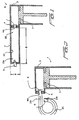
- FIGURE 8 an eighth embodiment of a pre-combustion chamber assembly constructed in accordance with the principles and teachings of the present invention is disclosed and is generally indicated by the reference character 20, and it is seen that the structure of this pre-combustion chamber assembly 20 is seen to be somewhat similar to that of the pre-combustion chamber 2 as disclosed within FIGURE 7A except that in lieu of the two-stage, vertically stacked spool-type array of FIGURE 7A , the pre-combustion chamber assembly 20 is seen to comprise a three-stage, vertically stacked spool type array.
- the pre-combustion chamber assembly 20 is seen to comprise a support base 22 which forms a first upper end wall 24 of the pre-combustion chamber assembly 20, and a pair of radially inner and radially outer cylindrical walls 26,28 which together form an annular pre-combustion chamber 30 therebetween.
- a pair of axially spaced, radially oriented annular partition walls 32,34 are integrally connected to and are interposed between the radially inner and radially outer cylindrical walls 26,28, and accordingly, the partition walls 32,34 effectively divide the pre-combustion chamber 30 into three vertically or axially separated pre-combustion chambers 30-1,30-2,30-3.
- An axially oriented partition wall 36 also structurally cooperates with upper end wall 24 and the pair of annular partition walls 32,34 in defining the three pre-combustion chambers 30-1,30-2,30-3.
- each one of the annular partition walls 32,34 is only partially complete in its circumferential extent and thereby effectively forms a pair of axially oriented ports 38,40 which, as will be described shortly hereinafter, serve to respectively fluidically interconnect pre-combustion chambers 30-1 and 30-2, and 30-2 and 30-3, to each other.
- an igniter can be located at a predetermined position within the vertically or axially uppermost one of the pre-combustion chambers 30-1, and upon the right side of the vertically or axially oriented partition wall 36, so as to accordingly initiate combustion that proceeds circumferentially around the upper one of the pre-combustion chambers 30-1 such that the flame front then propagates through the first axially oriented port 38 so as to enter the next or axially central one of the pre-combustion chambers 30-2.
- the flame front propagates through the second axially oriented port 40 so as to enter the lowermost one of the pre-combustion chambers 30-3.
- the lower end portion of the pre-combustion chamber assembly 20, and in particular, the lower end portion of the radially inner cylindrical wall portion 26 is further provided with a pair of diametrically opposite radially oriented ports 42,44 through which the flame front and unburned fuel and air from the pre-combustion chamber 30-3 can enter the lower end of an axially disposed final combustion chamber, not shown.
- An end wall 46 terminates the lower end of pre-combustion chamber 30-3.
- a check valve also not shown, is of course disposed within such lower end of the final combustion chamber, not shown, and may in fact be operatively associated with each one of the ports 42,44 in a manner similar to that of the seventh embodiment of FIGURE 7A , so as to freely control the admission of the flame front, and the unburned fuel and air, into the final combustion chamber, not shown, from the pre-combustion chamber assembly 20, but to effectively limit any backflow of combustion and combustion products from the final combustion chamber, not shown, into the pre-combustion chamber assembly 20.
- the final combustion chamber, not shown will of course also have a working piston, not shown, operatively associated therewith whereby, after the final combustion chamber, not shown, has received the unburned fuel and air from the pre-combustion chamber 30-3 as effectively forced into final combustion chamber, not shown, from pre-combustion chamber 30-3 by means of the propagating flame front, combustion occurs within the final combustion chamber, not shown, whereby, for example, the working piston, not shown, will be driven downwardly so as to in turn drive a fastener into a particular substrate.
- FIGURE 9 a ninth embodiment of a pre-combustion chamber assembly constructed in accordance with the principles and teachings of the present invention is disclosed and is generally indicated by the reference character 120, and it is seen that the structure of this pre-combustion chamber assembly 120 is seen to be susbstantially the same as that of the pre-combustion chamber assembly 20 as disclosed within FIGURE 8 except that the pre-combustion chamber assembly 120 has, in effect, been vertically upended with respect to the pre-combustion chamber assembly 20 of FIGURE 8 , the significance of which will become apparent shortly hereinafter.
- pre-combustion chamber assembly 120 in connection with the description of the structure comprising pre-combustion chamber assembly 120 as compared to that comprising pre-combustion chamber assembly 20, the component parts of the pre-combustion chamber assembly 120 which correspond to the component parts of the pre-combustion chamber assembly 20 will be noted by similar reference characters except that the reference characters for the pre-combustion chamber assembly 120 will be within the 100 series.
- the pre-combustion chamber assembly 120 is seen to comprise a support base 122 which forms a first lower end wall 124 of the pre-combustion chamber assembly 120, and a pair of radially inner and radially outer cylindrical walls 126,128 which together form an annular pre-combustion chamber 130 therebetween.
- a pair of axially spaced, radially oriented annular partition walls 132, 134 are integrally connected to and are interposed between the radially inner and radially outer cylindrical walls 126, 128, and accordingly, the partition walls 132,134 effectively divide the pre-combustion chamber 130 into three vertically or axially separated pre-combustion chambers 130-1, 130-2,130-3.
- An axially oriented partition wall 136 also structurally cooperates with lower end wall 124 and the pair of annular partition walls 132,134 in defining the three pre-combustion chambers 130-1,130-2,130-3.
- each one of the annular partition walls 132,134 is only partially complete in its circumferential extent and thereby effectively forms a pair of axially oriented ports 138,140 which, as will be described shortly hereinafter, serve to respectively fluidically interconnect pre-combustion chambers 130-1 and 130-2, and 130-2 and 130-3, to each other.
- an igniter can be located at a predetermined position within the vertically or axially lowermost one of the pre-combustion chambers 130-1, and upon the left side of the vertically or axially oriented partition wall 136, so as to accordingly initiate combustion that proceeds circumferentially around the lowermost one of the pre-combustion chambers 130-1 such that the flame front then propagates through the first axially oriented port 138 so as to enter the next or axially central one of the pre-combustion chambers 130-2.
- the flame front propagates through the second axially oriented port 140 so as to enter the uppermost one of the pre-combustion chambers 130-3.
- the upper end portion of the pre-combustion chamber assembly 120, and in particular, the upper end portion of the radially inner cylindrical wall portion 126 is further provided with a pair of diametrically opposite radially oriented ports 142,144 through which the flame front and unburned fuel and air from the pre-combustion chamber 130-3 can enter the upper end of an axially disposed final combustion chamber, not shown.
- An end wall 146 terminates the lower end of pre-combustion chamber 130-3.
- the final combustion chamber is adapted to be effectively housed or accommodated within the inner cylindrical wall 126 whereby combustion within the final combustion chamber, not shown, will propagate vertically or axially downwardly as viewed in FIGURE 9 .
- a check valve also not shown, is adapted to be disposed within such upper end of the final combustion chamber, not shown, and may in fact be operatively associated with each one of the ports 142,144 in a manner similar to that of the seventh embodiment of FIGURE 7A , so as to freely control the admission of the flame front, and the unburned fuel and air, into the final combustion chamber, not shown, from the pre-combustion chamber assembly 120, but to effectively limit any backflow of combustion and combustion products from the final combustion chamber, not shown, into the pre-combustion chamber assembly 120.
- the final combustion chamber, not shown will of course also have a working piston, not shown, operatively associated therewith whereby, after the final combustion chamber, not shown, has received the unburned fuel and air from the pre-combustion chamber 130-3 as effectively forced into the final combustion chamber, not shown, from pre-combustion chamber 130-3 by means of the propagating flame front, combustion occurs within the final combustion chamber, not shown, whereby, for example, the working piston, not shown, will be driven downwardly so as to in turn drive a fastener into a particular substrate.
- a combustion chamber system comprising an elongated pre-combustion chamber used in combination with a final combustion chamber, and in conjunction with such pre-combustion chambers, there has been provided unique structural arrangements wherein the pre-combustion chambers have been rendered spatially compact and efficient. More particularly, the pre-combustion chambers have been effectively divided into a plurality of axially separated but stacked pre-combustion chambers or sections which effectively form two and three-stage pre-combustion chamber structures or assemblies. Still further, in order to additionally render the pre-combustion chamber and final combustion assembly still more compact, the final combustion chamber has effectively been axially housed or accommodated internally within the pre-combustion assembly.
Abstract
Description
- The present invention relates generally to combustion chamber systems, and more particularly to a new and improved combustion chamber system for use in connection with combustion-powered tools for driving fasteners into workpieces or substrates wherein the combustion chamber system comprises a pre-combustion chamber and a final combustion chamber wherein the aspect ratio of the pre-combustion chamber, defined by the ratio of the length of the pre-combustion chamber with respect to the width of the pre-combustion chamber, is at least 2:1 whereby the performance or output power levels of the combustion process can be dramatically improved resulting in greater driving forces, greater acceleration levels and greater velocity levels of the working piston, and greater driving depths of fasteners into their respective substrates.
- As has been noted within the aforenoted patent application, combustion chamber systems have been previously developed wherein the combustion chamber comprises, or is effectively divided into, a pre-combustion chamber and a final combustion chamber. Examples of such dual combustion chamber systems are disclosed within
United States Patent 4,665,868 which issued to Adams on May 19, 1987,United States Patent 4,510,748 which issued to Adams on April 16, 1985, andUnited States Patent 4,365,471 which issued to Adams on December 28, 1982. In accordance with such systems, combustion initiated within the pre-combustion chamber geneates a flame front that drives and compresses unburned fuel and air toward and into the final combustion chamber whereby the work output of the system is significantly enhanced. - More particularly, when a combustion cycle is initiated, both the pre-combustion chamber and the final combustion chamber are charged with a mixture of fuel and air, and the mixture within the pre-combustion chamber is then ignited. The generated flame front then propagates through the pre-combustion chamber so as to push unburned fuel and air in front of it toward the final combustion chamber. A check valve effectively separates the pre-combustion and final combustion chambers so as to permit the flame front to enter the final combustion chamber from the pre-combustion chamber but to limit any reverse flow of combustion products from the final combustion chamber back into the pre-combustion chamber. As the flame front enters the final combustion chamber, it ignites the compressed fuel and air mixture disposed within the final combustion chamber. This process elevates the combustion pressure within the final combustion chamber leading to a more efficient combustion within the final combustion chamber. Accordingly, such higher pressures can more effectively and powerfully perform useful work, such as, for example, the driving of fasteners through and out from combustion-powered fastener-driving tools.
- As further disclosed within the aforenoted United States Patent application, by increasing the aspect ratio, which is defined as the ratio of the length-to-width dimensions, of the pre-combustion chamber, the performance of the combustion process can be dramatically improved. More particularly, constructing the pre-combustion chamber so as to be significantly longer than wider runs counter to the conventionally recognized wisdom of designing combustion chamber systems to be as compact as possible, however, it was discovered that a long and narrow pre-combustion chamber can effectively push more unburned fuel and air ahead of a flame front and into the final combustion chamber than was possible with a conventional, normally short and wide pre-combustion chamber. Again, this process elevates the combustion pressure within the final combustion chamber leading to a more efficient combustion within the final combustion chamber, and accordingly, such higher pressures can more effectively and more powerfully perform useful work, such as, for example, the driving of fasteners through and out from combustion-powered fastener-driving tools.
- It is also desirable, and even necessary or mandatory that, in connection with the use of certain combustion-powered fastener-driving tools, the tools be readily portable, relatively light in weight, and relatively small in size. Accordingly, it is desirable to achieve the aforenoted combustion process wherein the combustion pressure within the final combustion chamber is substantially elevated so as to lead to more efficient combustion within the final combustion chamber whereby such higher pressures can more effectively and more powerfully perform useful work, such as, for example, the driving of fasteners through and out from combustion-powered fastener-driving tools, and yet the tools must be readily portable, relatively light in weight, and relatively small in size.
- A need therefore exists in the art for a new and improved combustion-powered tool which has incorporated therein suitable structure which is capable of readily attaining enhanced energy output levels such that the resulting energy derived from the combustion-powered tool enables the combustion-powered tool to be used in connection with the installation of fasteners into substrates or workpieces, and yet the internal structure incorporated within the tool for achieving the desired energy output levels is itself compact so as to in turn render the overall tool readily portable, relatively light in weight, and relatively small in size.
- Accordingly, it is an object of the present invention to provide a new and improved combustion-powered tool.
- Another object of the present invention is to provide a new and improved combustion-powered tool which effectively overcomes the various operational disadvantages and drawbacks characteristic of PRIOR ART combustion-powered tools.
- An additional object of the present invention is to provide a new and improved combustion-powered tool wherein the resulting or derived energy levels, characteristic of the combustion process within the combustion-powered tool, is readily enhanced.
- A further object of the present invention is to provide a new and improved combustion-powered tool wherein the resulting or derived energy levels, characteristic of the combustion process within the combustion-powered tool, is readily enhanced so as to enable the combustion-powered tool to generate elevated driving forces, acceleration, and velocity characteristics or parameters.
- A last object of the present invention is to provide a new and improved combustion-powered tool wherein the resulting or derived energy levels, characteristic of the combustion process within the combustion-powered tool, are readily enhanced so as to enable the combustion-powered tool to generate elevated driving forces, acceleration, and velocity characteristics or parameters by means of compact structure so as to in turn render the overall tool readily portable, relatively light in weight, and relatively small in size.
- The foregoing and other objectives are achieved in accordance with the teachings and principles of the present invention through the provision of a new and improved combustion-powered tool which comprises a combustion chamber system according to
claim 1. - It should be noted that the features of the preamble portion of that
claim 1 are tought byUS 4 665 868 . - Various other objects, features, and attendant advantages of the present invention will be more fully appreciated from the following detailed description when considered in connection with the accompanying drawings in which like reference characters designate like or corresponding parts throughout the several views, and wherein:
-
FIGURE 1 is a schematic cross-sectional view of a first embodiment of a combustion chamber system constructed in accordance with the principles and teachings of the present invention and showing the structure and relative disposition of the pre-combustion and final combustion chambers thereof wherein the pre-combustion and final combustion chambers are both linear and coaxially arranged with respect to each other, however, the axis of the fastener-driving piston is substantially perpendicular to the common axis of the pre-combustion and final combustion chambers; -
FIGURE 2 is a view similar to that ofFIGURE 1 showing, however, a second embodiment of a combustion chamber system constructed in accordance with the principles and teachings of the present invention wherein the pre-combustion chamber is curved; -
FIGURE 3A is a view similar to that ofFIGURE 1 showing, however, a third embodiment of a combustion chamber system constructed in accordance with the principles and teachings of the present invention wherein the pre-combustion chamber comprises a plurality of curved sections which are disposed in a nested arrangement; -
FIGURE 3B is a cross-sectional view of the combustion chamber system disclosed withinFIGURE 3A as taken along the lines 3B-3B ofFIGURE 3A ; -
FIGURE 4 is a view similar to that ofFIGURE 1 showing, however, a fourth embodiment of a combustion chamber system constructed in accordance with the principles and teachings of the present invention and showing the structure and relative disposition of the pre-combustion and final combustion chambers thereof wherein the pre-combustion and final combustion chambers are both linear and coaxially arranged with respect to each other, and wherein further, the axis of the fastener-driving piston is likewise coaxial with the common axis of the pre-combustion and final combustion chambers; -
FIGURE 5A is a view similar to that ofFIGURE 3A showing, however, a fifth embodiment of a combustion chamber system constructed in accordance with the principles and teachings of the present invention wherein each one of the pre-combustion and final combustion chambers comprises a plurality of curved sections which are disposed in a nested arrangement; -
FIGURE 5B is a cross-sectional view of the combustion chamber system disclosed withinFIGURE 5A as taken along the lines 5B-5B ofFIGURE 5A ; -
FIGURE 5C is a cross-sectional view of the combustion chamber system disclosed withinFIGURE 5A as taken along the lines 5C-5C ofFIGURE 5A ; -
FIGURE 6A is a view similar to that ofFIGURE 3A showing, however, a sixth embodiment of a combustion chamber system constructed in accordance with the principles and teachings of the present invention wherein each one of the pre-combustion and final combustion chambers comprises a plurality of curved sections which are disposed in a nested arrangement; -
FIGURE 6B is a cross-sectional view of the combustion chamber system disclosed withinFIGURE 6A as taken along the lines 6B-6B ofFIGURE 6A ; -
FIGURE 6C is a cross-sectional view of the combustion chamber system disclosed withinFIGURE 6A as taken along the lines 6C-6C ofFIGURE 6A ; -
FIGURE 7A is a view similar to that ofFIGURE 3A showing, however, a seventh embodiment of a combustion chamber system constructed in accordance with the principles and teachings of the present invention wherein the pre-combustion chamber comprises a plurality of curved sections which are disposed in a vertically stacked spool arrangement; -
FIGURE 7B is a cross-sectional view of the combustion chamber system disclosed withinFIGURE 7A as taken along the lines 7B-7B ofFIGURE 7A ; -
FIGURE 7C is a cross-sectional view of the combustion chamber system disclosed withinFIGURE 7A as taken along the lines 7C-7C ofFIGURE 7A ; and -
FIGURE 8 is a perspective view partially similar to that ofFIGURE 7A showing, however, an eighth embodiment of the present invention wherein a three-stage spool-type pre-combustion chamber is disclosed; and -
FIGURE 9 is a view similar to that ofFIGURE 8 showing, however, a ninth embodiment of the present invention wherein an alternatively arranged or oriented three-stage spool-type pre-combustion chamber is disclosed. - It should be right away pointed our that the embodiments of
figures 1-6C do not form part of the invention but represent background art useful for understanding the invention. - The interests of compact mechanical design have resulted in PRIOR ART combustion systems having a relatively short length and diameters or widths which are generally much greater than their lengths. However, experiments in lengthening pre-combustion chambers wherein their length to width aspect ratios are greatly increased has revealed the fact that higher aspect ratio pre-combustion chambers are much more effective at forcing unburned fuel and air, ahead of an advancing flame front, into a final combustion chamber. This improvement increases the pressure within the final combustion chamber before ignition occurs there, and this greatly increases the power which is obtainable or capable of being derived from the combustion within the final combustion chamber. The reasons why elongated pre-combustion chambers accomplish this result remain unclear, however, experimental evidence verifies the fact that elongated pyre-combustion chambers do succeed in forcing more unburned fuel and air into the final combustion chamber so as to achieve increased power output levels. It is reasonable to assume, for example, that the increased amount of fuel and air pumped into the final combustion chamber from an elongated pre-combustion chamber occurs in advance of a flame front proceeding from the ignition end of the pre-combustion chamber toward the discharge end of the pre-combustion chamber which communicates with the final combustion chamber. The improvement in power output from the final combustion chamber can be increased by as much as fifty percent (50%) simply by elongating the pre-combustion chamber wherein the same has an optimum aspect ratio. More particularly, in accordance with the principles and teachings of the present invention, combustion chamber systems with elongated pre-combustion chambers having length to width ratios over a broad range have been tested and it has been noted that some improvement in performance has been achieved when the aspect ratio is on the order of 2:1. Even better performance has been achieved when the aspect ratio is within the range of 4:1 to 16:1, and still further, peak performance has been attained when the aspect ratio is approximately 10:1. In summary, the results tend to show that the improvement in performance derived from an elongated linear pre-combustion chamber tends to simulate a bell-shaped curve which has its peak centered at an aspect ratio of approximately 10:1. It has been additionally noted that discontinuities or irregularities present within or upon the internal surfaces of the pre-combustion chamber should be avoided in view of the fact that such structures tend to degrade power output. Still further, it has been noted that the pre-combustion chambers can comprise round, oval, rectangular, or other cross-sectional configurations whereby they will all function desirably well as long as the length of the pre-combustion chamber is substantially greater than the average width. Yet further, it has been noted that the elongated pre-combustion chambers readily enable the scavenging of exhaust gases.
- It has also been determined that in addition to the elongated pre-combustion chambers having the aforenoted geometrical configurations, the elongated pre-combustion chambers which are capable of generating substantially increased piston power output can be curved, or folded, in effect, back onto itself. Again, as long as the curved or folded pre-combustion chambers have relatively high aspect ratios, the aforenoted performance advantages will be able to be achieved. It has been found, for example, that a flame front created or generated within such elongated and curved pre-combustion chambers propagates relatively faster. More particularly, curving an elongated pre-combustion chamber along its length seems to shift the aforenoted bell-shaped curve as well as decrease the overall combustion time within the pre-combustion chamber. It has therefore been found or determined that by curving or folding the elongated pre-combustion chamber, increased power and shorter combustion times have been able to be achieved at significantly higher aspect ratio values, such as, for example, within the range of 15:1 to 30:1. More particularly, the pre-combustion chambers can be formed from or comprise curved sections that are joined in series, nested together, and/or combined with straight combustion chambers or combustion chamber sections so as to form compact assemblages which are capable of achieving the objective advantages of the present invention.
- It has been determined further that the output performance of the elongated pre-combustion chambers can be influenced by means of the aspect ratios concerning the width and thickness dimensions of the pre-combustion chambers. For example, an elongated pre-combustion chamber which has a rectangular cross-section and which would therefore be expected to exhibit enhanced output performance characteristics will fail to perform well if the aspect ratio of the width to thickness dimensions is relatively high. In other words, as the structure, shape, or configuration of an elongated pre-combustion chamber approaches that of a thin ribbon, it can become too constricted so as not to be capable of successfully pumping unburned fuel and air into the final combustion chamber. Experiments have indicated that an optimal or desirable width to thickness aspect ratio for elongated pre-combustion chambers is 4:1 or less.
- Referring now to the drawings, and more particularly to
FIGURE 1 thereof, the combustion chamber system is generally indicated by thereference character 1 and is seen to comprise a pre-combustion chamber orplenum 2 and a final combustion chamber orplenum 3 wherein the pre-combustion and final combustion chambers orplenums combustion control wall 4. Anigniter 5 is disposed within afirst end portion 2A of thepre-combustion chamber 2, and it is seen that thefinal combustion chamber 3 is disposed adjacent to the secondopposite end 2B of thepre-combustion chamber 2. Anaperture 4A is defined within thecombustion control wall 4 so as to permit the flame front generated within thepre-combustion chamber 2 by means of theigniter 5 to pass through thecombustion control wall 4 and into thefinal combustion chamber 3. Ignition of the fuel and air mixture within thefinal combustion chamber 3 then serves to drive a workingpiston 7. In accordance with the principles and teachings of the present invention, and unlike PRIOR ART combustion chamber systems, it is seen thatpre-combustion chamber 2 has a predetermined length dimension B and a predetermined width dimension A wherein the length B is substantially greater than the width A. More particularly, the ratio of the length B to the width A, known as the aspect ratio of thepre-combustion chamber 2, is at least 2:1. Acheck valve 6 is operatively disposed within thefinal combustion chamber 3 and is disposed adjacent to theaperture 4A defined within thecombustion control wall 4 so as to minimally impede, and therefore to effectively allow, the free flow of a fuel and air mixture from thepre-combustion chamber 2 into thefinal combustion chamber 3. Subsequently, when combustion is initiated within thefinal combustion chamber 3, the pressure present therein rapidly increases and consequently,check valve 6 is closed so as to limit and effectively prevent any back flow from occurring fromfinal combustion chamber 3 intopre-combustion chamber 2. It is further noted that the interiorperipheral surface 2C of thepre-combustion chamber 2 is substantially smooth and free of protrusions or irregularities, and the average distance defined between diametrically opposite side wall surfaces of the interiorperipheral wall surface 2C ofpre-combustion chamber 2 constitutes the width A. - With reference now being made to
FIGURE 2 , it is seen that the structure of thefinal combustion chamber 3, as well as its dispositional relationship with respect to the workingpiston 7, is substantially the same as that offinal combustion chamber 3 as in the first embodiment ofFIGURE 1 , however, in accordance with the second embodiment of the present invention as disclosed withinFIGURE 2 , it is seen that thepre-combustion chamber 2 comprises a curved section integrally connected to a lineal section so as to render the entirepre-combustion chamber 2 more spatially compact. More particularly, apre-combustion chamber 2 such as that illustrated inFIGURE 2 permits pre-combustion chambers characterized by higher aspect ratios to achieve results which are similar to results attained using elongated linear pre-combustion chambers having similar aspect ratios but requiring substantially more lineal space. It is to be noted that, in accordance with the structure comprising the second embodiment ofFIGURE 2 , the length of thepre-combustion chamber 2 is measured from theigniter end 2A of thepre-combustion chamber 2 to the combustioncontrol wall end 2B of thepre-combustion chamber 2 along a line which is substantially equidistant between the oppositely disposed side wall surface portions of the interiorperipheral wall surface 2C of thepre-combustion chamber 2. The curved section of thepre-combustion chamber 2 is also seen to have an angular extent of approximately 270°. - With reference now being made to
FIGURES 3A and 3B , and in accordance with further spatial conservation techniques developed in accordance with the principles and teachings of the present invention, it is seen that thepre-combustion chamber 2 comprises a plurality ofcurved sections 2D which are fluidically arranged in series and are nested together so as to be disposed within a substantially common plane and thereby effectively form a three-stagepre-combustion chamber 2. Alternatively, the overallpre-combustion chamber 2 could have a substantially S-shaped configuration, a spiral configuration, or some other configuration comprising a combination of straight and curved sections. Curvedpre-combustion chamber 2 such as that illustrated withinFIGURES 3A and 3B is formed by means of integrally connecting together different cylinders, having different diametrical extents, in the noted coaxial array. It is therefore to be appreciated, in conjunction with the operation of thepre-combustion chamber 2 as disclosed withinFIGURES 3A and 3B , that a flame front initiated by ignition of theigniter 5 within theregion 2A of the first outermostpre-combustion chamber portion 2D first travels around the outermost periphery of thepre-combustion chamber 2, and subsequently enters a second intermediateperipheral portion 2D of thepre-combustion chamber 2 through means of a first radially oriented port fluidically connecting the outermost and intermediate peripheral flow paths of thepre-combustion chamber 2. - The flame front then continues to travel around the intermediate
peripheral portion 2D of thepre-combustion chamber 2 and subsequently enters a third innermostpre-combustion chamber portion 2D of thepre-combustion chamber 2 through means of a second radially oriented port fluidically connecting the intermediate and innermost peripheral flow paths of thepre-combustion chamber 2. Ultimately, the flame front then passes by or through a centrally locatedcheck valve 6 so as to enter thefinal combustion chamber 3. Alternatively, ignition could be initiated within a central chamber whereby the flame front would be fluidically conducted and propagated in effect radially outwardly from an inner peripheralpre-combustion chamber portion 2D to an outer peripheralpre-combustion chamber portion 2D of thepre-combustion chamber 2, and ultimately into thefinal combustion chamber 3. Either way, the movement of the flame front within the curved and substantially foldedpre-combustion chamber portions 2D forces unburned fuel and air through thecheck valve 6 and into thefinal combustion chamber 3 so as to increase the pressure of the unburned fuel and air withinfinal combustion chamber 3. Such an increase in the operative pressure significantly increases the combustion power output offinal combustion chamber 3 as operatively applied to driving theworking piston 7. It is to be noted that the improvement afforded by increasing the aspect ratio of thecombustion chamber 1 can be as much as a fifty percent (50%) increase in the power output exhibited bypiston 7. - With reference now being made to
FIGURE 4 , a variation of the first embodiment as disclosed withinFIGURE 1 is disclosed withinFIGURE 4 wherein it is seen that thepre-combustion chamber 2, thefinal combustion chamber 3, and the drive chamber within which thepiston 7 is operatively disposed are all coaxially arranged with respect to each other. The volumes of thepre-combustion chamber 2 and thefinal combustion chamber 3 of this fourth embodiment are substantially equal whereby satisfactory increases in power output are achieved in accordance with the objectives of the present invention, and it is noted further that the length to width aspect ratio of thepre-combustion chamber 2 of the fourth embodiment ofFIGURE 4 is approximately 4:1. - Continuing still further, and with reference now being made to
FIGURES 5A-5C , a fifth embodiment of a combustion chamber system constructed in accordance with the principles and teachings of the present invention is disclosed and it is seen that this embodiment is somewhat similar to the third embodiment shown inFIGURES 3A and 3B in that thepre-combustion chamber 2 comprises a three-stage pre-combustion chamber structure, however, in addition,final combustion chamber 3 likewise comprises a three-stage combustion chamber structure. Still further, it is appreciated that thepre-combustion chamber 2 of this fifth embodiment differs from thepre-combustion chamber 2 of the third embodiment as disclosed withinFIGURES 3A and 3B in that theigniter 5 is disclosed at a central or axial position with respect to thepre-combustion chamber 2 and therefore the flame front effectively propagates from a radially inner portion of thepre-combustion chamber 2 through radially orientedports 2E to a radially outer portion of thepre-combustion chamber 2. Concomitantly therewith, the flame front will be introduced into thefinal combustion chamber 3, through means ofcheck valve 6, at a radially outer portion of thecombustion chamber system 1 and be conducted toward a radially inner or axial position of the combustion chamber system at which theworking piston 7 is located. The sixth embodiment of the present invention as disclosed withinFIGURES 6A-6C is substantially the same as that of the fifth embodiiment ofFIGURES 5A-5C with the additional disclosure of anintake valve 8 being disposed within an outer peripheral wall portion of thepre-combustion chamber 2D while anexhaust valve 9 is similarly disposed within an outer peripheral wall portion of thefinal combustion chamber 3. This arrangement serves to compactly accommodate the purging requirements of exhaust gases from thefinal combustion chamber 3, as well as fuel and air intake requirements into thepre-combustion chamber 2. - With reference now being made to
FIGURES 7A-7C , a seventh embodiment of the present invention is seen to be disclosed, and in accordance with this embodiment, it is appreciated that thepre-combustion chamber 2 has been divided into two coaxially arrangedsections 2D wherein thesections 2D are also axially separated from each other so as to be disposed, for example, within a two-stage, vertically stacked spool-type array. Theigniter 5 is located at a predetermined circumferential position within the vertically upper one of thepre-combustion chamber sections 2D and accordingly initiates combustion that proceeds around the upper one of thepre-combustion chamber sections 2D such that the flame front then propagates through an aperture or opening 3C which fluidically connects the upper one of thepre-combustion chamber sections 2D to the lower one of thepre-combustion chamber sections 2D. - After traversing the lower one of the
pre-combustion chamber sections 2D, the flame front propagates toward thecheck valve 6 whereupon passing throughcheck valve 6, the flame front enters the cylindricalfinal combustion chamber 3 which is seen to be disposed radially inwardly of the annularly surroundingpre-combustion chamber sections 2D. The flame front enters thefinal combustion chamber 3 at a position adjacent to the workingpiston 7 after thefinal combustion chamber 3 receives unburned fuel and air from thepre-combustion chamber 2 as effectively forced intofinal combustion chamber 3 frompre-combustion chamber 2 by means of the propagating flame front. Exhaust from thefinal combustion chamber 3 is permitted to occur through anexhaust valve 9 which is located within an end wall of thefinal combustion chamber 3 which is disposed opposite the workingpiston 7, while fuel and air intake into the upperpre-combustion chamber section 2D occurs through means ofintake valve 8 preferably disposed adjacent toigniter 5. - As has been noted heretofore,
check valve 6 should be as free-flowing as possible, and accordingly, it has been determined thatcheck valve 6 can be either a normally OPEN or a normally CLOSED type of check valve. In either case, thecheck valve 6 will be disposed in an OPEN state so as to allow a relatively free flow of gases from thepre-combustion chamber 2 into thefinal combustion chamber 3 and will subsequently be disposed in its CLOSED state when the fuel and air mixture within the final combustion chamber is ignited. It may also be desirable in connection with some applications, in order to properly scavenge exhaust gases or to distribute unburned fuel and air through the system, to make thecheck valve 6 free-flowing in both directions at low pressure levels. The increased pressure level that promptly follows ignition within thefinal combustion chamber 3 will then quickly close thecheck valve 6 so as to limit or effectively prevent back-flow from thefinal combustion chamber 3 back into thepre-combustion chamber 2. Checkvalve 6 may also be arranged so as to quench a pre-combustion flame front after admitting unburned fuel and air into thefinal combustion chamber 3. An igniter within thefinal combustion chamber 3 can then initiate combustion within thefinal combustion chamber 3. - With reference now being made to
FIGURE 8 , an eighth embodiment of a pre-combustion chamber assembly constructed in accordance with the principles and teachings of the present invention is disclosed and is generally indicated by thereference character 20, and it is seen that the structure of thispre-combustion chamber assembly 20 is seen to be somewhat similar to that of thepre-combustion chamber 2 as disclosed withinFIGURE 7A except that in lieu of the two-stage, vertically stacked spool-type array ofFIGURE 7A , thepre-combustion chamber assembly 20 is seen to comprise a three-stage, vertically stacked spool type array. More particularly, thepre-combustion chamber assembly 20 is seen to comprise asupport base 22 which forms a firstupper end wall 24 of thepre-combustion chamber assembly 20, and a pair of radially inner and radially outercylindrical walls pre-combustion chamber 30 therebetween. - A pair of axially spaced, radially oriented
annular partition walls cylindrical walls partition walls pre-combustion chamber 30 into three vertically or axially separated pre-combustion chambers 30-1,30-2,30-3. An axially orientedpartition wall 36 also structurally cooperates withupper end wall 24 and the pair ofannular partition walls annular partition walls ports - More particularly, it can therefore be appreciated that an igniter, not shown, can be located at a predetermined position within the vertically or axially uppermost one of the pre-combustion chambers 30-1, and upon the right side of the vertically or axially oriented
partition wall 36, so as to accordingly initiate combustion that proceeds circumferentially around the upper one of the pre-combustion chambers 30-1 such that the flame front then propagates through the first axially orientedport 38 so as to enter the next or axially central one of the pre-combustion chambers 30-2. In a manner similar to the propagation of the flame front within the uppermost one of the pre-combustion chambers 30-1, that is, after circumferentially traversing the axially central one of the pre-combustion chambers 30-2, the flame front propagates through the second axially orientedport 40 so as to enter the lowermost one of the pre-combustion chambers 30-3. The lower end portion of thepre-combustion chamber assembly 20, and in particular, the lower end portion of the radially innercylindrical wall portion 26 is further provided with a pair of diametrically opposite radially orientedports end wall 46 terminates the lower end of pre-combustion chamber 30-3. - As was the case with the previously disclosed embodiments, a check valve, also not shown, is of course disposed within such lower end of the final combustion chamber, not shown, and may in fact be operatively associated with each one of the
ports FIGURE 7A , so as to freely control the admission of the flame front, and the unburned fuel and air, into the final combustion chamber, not shown, from thepre-combustion chamber assembly 20, but to effectively limit any backflow of combustion and combustion products from the final combustion chamber, not shown, into thepre-combustion chamber assembly 20. The final combustion chamber, not shown, will of course also have a working piston, not shown, operatively associated therewith whereby, after the final combustion chamber, not shown, has received the unburned fuel and air from the pre-combustion chamber 30-3 as effectively forced into final combustion chamber, not shown, from pre-combustion chamber 30-3 by means of the propagating flame front, combustion occurs within the final combustion chamber, not shown, whereby, for example, the working piston, not shown, will be driven downwardly so as to in turn drive a fastener into a particular substrate. - With reference lastly being made to
FIGURE 9 , a ninth embodiment of a pre-combustion chamber assembly constructed in accordance with the principles and teachings of the present invention is disclosed and is generally indicated by thereference character 120, and it is seen that the structure of thispre-combustion chamber assembly 120 is seen to be susbstantially the same as that of thepre-combustion chamber assembly 20 as disclosed withinFIGURE 8 except that thepre-combustion chamber assembly 120 has, in effect, been vertically upended with respect to thepre-combustion chamber assembly 20 ofFIGURE 8 , the significance of which will become apparent shortly hereinafter. It is therefore to be noted further that in connection with the description of the structure comprisingpre-combustion chamber assembly 120 as compared to that comprisingpre-combustion chamber assembly 20, the component parts of thepre-combustion chamber assembly 120 which correspond to the component parts of thepre-combustion chamber assembly 20 will be noted by similar reference characters except that the reference characters for thepre-combustion chamber assembly 120 will be within the 100 series. - More particularly then, the
pre-combustion chamber assembly 120 is seen to comprise a support base 122 which forms a firstlower end wall 124 of thepre-combustion chamber assembly 120, and a pair of radially inner and radially outer cylindrical walls 126,128 which together form an annularpre-combustion chamber 130 therebetween. A pair of axially spaced, radially orientedannular partition walls cylindrical walls pre-combustion chamber 130 into three vertically or axially separated pre-combustion chambers 130-1, 130-2,130-3. An axially oriented partition wall 136 also structurally cooperates withlower end wall 124 and the pair of annular partition walls 132,134 in defining the three pre-combustion chambers 130-1,130-2,130-3. In addition, it is also seen that each one of the annular partition walls 132,134 is only partially complete in its circumferential extent and thereby effectively forms a pair of axially oriented ports 138,140 which, as will be described shortly hereinafter, serve to respectively fluidically interconnect pre-combustion chambers 130-1 and 130-2, and 130-2 and 130-3, to each other. It can therefore be appreciated that, as was the case with thepre-combustion chamber assembly 20, an igniter, not shown, can be located at a predetermined position within the vertically or axially lowermost one of the pre-combustion chambers 130-1, and upon the left side of the vertically or axially oriented partition wall 136, so as to accordingly initiate combustion that proceeds circumferentially around the lowermost one of the pre-combustion chambers 130-1 such that the flame front then propagates through the first axially orientedport 138 so as to enter the next or axially central one of the pre-combustion chambers 130-2. In a manner similar to the propagation of the flame front within the lowermost one of the pre-combustion chambers 130-1, that is, after circumferentially traversing the axially central one of the pre-combustion chambers 130-2, the flame front propagates through the second axially orientedport 140 so as to enter the uppermost one of the pre-combustion chambers 130-3. The upper end portion of thepre-combustion chamber assembly 120, and in particular, the upper end portion of the radially innercylindrical wall portion 126 is further provided with a pair of diametrically opposite radially oriented ports 142,144 through which the flame front and unburned fuel and air from the pre-combustion chamber 130-3 can enter the upper end of an axially disposed final combustion chamber, not shown. Anend wall 146 terminates the lower end of pre-combustion chamber 130-3. - In accordance with the unique arrangement of the
pre-combustion chamber assembly 120, particularly in connection with the final combustion chamber, not shown, and in a manner similar to the embodiments disclosed withinFIGURES 7A and8 , the final combustion chamber, not shown, is adapted to be effectively housed or accommodated within the innercylindrical wall 126 whereby combustion within the final combustion chamber, not shown, will propagate vertically or axially downwardly as viewed inFIGURE 9 . Accordingly, as was the case with the previously disclosed embodiments, a check valve, also not shown, is adapted to be disposed within such upper end of the final combustion chamber, not shown, and may in fact be operatively associated with each one of the ports 142,144 in a manner similar to that of the seventh embodiment ofFIGURE 7A , so as to freely control the admission of the flame front, and the unburned fuel and air, into the final combustion chamber, not shown, from thepre-combustion chamber assembly 120, but to effectively limit any backflow of combustion and combustion products from the final combustion chamber, not shown, into thepre-combustion chamber assembly 120. The final combustion chamber, not shown, will of course also have a working piston, not shown, operatively associated therewith whereby, after the final combustion chamber, not shown, has received the unburned fuel and air from the pre-combustion chamber 130-3 as effectively forced into the final combustion chamber, not shown, from pre-combustion chamber 130-3 by means of the propagating flame front, combustion occurs within the final combustion chamber, not shown, whereby, for example, the working piston, not shown, will be driven downwardly so as to in turn drive a fastener into a particular substrate. - Thus, it may be seen that in accordance with the principles and teachings of the present invention, there has been disclosed a combustion chamber system comprising an elongated pre-combustion chamber used in combination with a final combustion chamber, and in conjunction with such pre-combustion chambers, there has been provided unique structural arrangements wherein the pre-combustion chambers have been rendered spatially compact and efficient. More particularly, the pre-combustion chambers have been effectively divided into a plurality of axially separated but stacked pre-combustion chambers or sections which effectively form two and three-stage pre-combustion chamber structures or assemblies. Still further, in order to additionally render the pre-combustion chamber and final combustion assembly still more compact, the final combustion chamber has effectively been axially housed or accommodated internally within the pre-combustion assembly.
- Obviously, many variations and modifications of the present invention are possible in light of the above teachings. More particularly, it is to be noted, as has been reflected by means of the various different embodiments already disclosed, that an endless variety of configurations, geometries, and proportions can implement or embody an elongated pre-combustion chamber so as to effectively increase the power output levels which are obtainable from the final combustion chamber. It is therefore to be understood that within the scope of the appended claims, the present invention may be practiced otherwise than as specifically described herein.
Claims (16)
- A combustion chamber system (1), comprising :a pre-combustion chamber (2) comprising a first end wall, a second end wall disposed opposite said first end wall such that the distance defined between said first and second end walls defines the length B of said pre-combustion chamber, a first side wall, and a second side wall disposed opposite said first side wall such that the distance defined between said first and second side walls defines the width A of said pre-combustion chamber ; wherein said length of said pre-combustion chamber is greater than said width of said pre-combustion chamber ;a final combustion chamber (3) fluidically connected to said pre-combustion chamber;an ignition device (5) operatively associated with said pre-combustion chamber so as to initiate combustion of a combustible mixture within said pre-combustion chamber;characterized in thatsaid length of said pre-combustion chamber is greater than said width of said pre-combustion chamber ;said pre-combustion chamber comprising a plurality of pre-combustion chamber sections (2D) fluidically connected together and arranged within a multi-stage axially stacked annular array around an axis and having a predetermined axial extend ; andwherein said final combustion chamber (3) having a predetermined axial extend is accommodated internally within said multi-usage axially stacked annular array of said pre-combustion chamber sections.
- A combustion chamber system as set forth in claim 1 for use in connection with the driving of a working piston.
- The combustion chamber system as set forth in claim 1 or 2, wherein :the aspect ratio of said pre-combustion chamber (2), defined as the ratio of said length B of said pre-combustion chamber to said width A of said pre-combustion chamber, is at least 2:1.
- The combustion chamber system as set forth in claim 3, wherein :the aspect ratio of said pre-combustion chamber is within the range of 2:1 to 16:1.
- The combustion chamber system as set forth in any one of the preceeding claims, wherein :interior surface portions of said pre-combustion chamber are substantially smooth.
- The combustion chamber system as set forth in any one of the preceeding claims, wherein :said axial extent of said pre-combustion chamber and said axial extent of said final combustion chamber are substantially equal.
- The combustion chamber system as set forth in any one of the preceeding claims, wherein :said pre-combustion chamber and said final combustion chambers are coaxially disposed with respect to each other.
- The combustion chamber system as set forth in any one of the preceeding claims, wherein :an end wall of said final combustion chamber is provided with an exhaust port for exhausting combustion products toward a member upon which work is to be performed.
- The combustion chamber system as set forth in any one of the preceeding claims, wherein :a combustion control wall, having an aperture defined therein, is interposed between and separates said pre-combustion chamber and said final combustion chamber.
- The combustion chamber system a set forth in any one of the preceeding claims, wherein :said pre-combustion chamber (2) comprising a plurality of pre-combustion chamber section (2D) fluidically connected to each other comprises a first radially inner cylindrical member, a second radially outer cylindrical member, an axially oriented partition wall for separating opposite ends of said pre-combustion chamber sections, and at least one radially oriented partition wall for dividing said pre-combustion chamber into said plurality of pre-combustion sections.
- The combustion chamber system as set forth in claim 10, wherein :said pre-combustion chamber comprising said plurality of pre-combustion chamber sections fluidically connected together comprises a two-stage axially stacked annular array.
- The combustion chamber system as set forth in Claim 11, wherein said two-stage axially stacked annular array pre-combustion chamber comprises:a first annular pre-combustion chamber section defined between said radially inner and radially outer cylindrical members and having a first end portion disposed at a predetermined circumferential location with respect to said axis, an igniter disposed within said first end portion of said first annular precombustion chamber section, and an annular flow path which extends circumferentially from said first end portion to a second end portion which is disposed at a predetermined circumferential location which is disposed adjacent to said first predetermined circumferential location at which said first end portion is located;a second annular pre-combustion chamber section defined between said radially inner and radially outer cylindrical members and having a first end portion disposed at a predetermined circumferential location with respect to said axis which is substantially axially aligned with said second end portion of said first annular pre-combustion chamber section, and an annular flow path which extends circumferentially from said first end portion of said second annular precombustion chamber section to a second end portion which is disposed at a predetermined circumferential location which is disposed adjacent to said first end portion of said second annular pre-combustion chamber section is located, and which is fluidically connected to said final combustion chamber; andan axially oriented port fluidically interconnecting said second end portion of said first annular pre-combustion chamber section with said first end portion of said second annular pre-combustion chamber section such that said first and second annular pre-combustion chamber sections are fluidically connected together.
- The combustion chamber system as set forth in claim 10, wherein:said pre-combustion chamber comprising said plurality of pre-combustion chamber section fluidically connected together comprises a three-stage axially stacked annular array.
- The combustion chamber system as set forth in claim 13 , wherein said three-stage axially stacked annular array pre-combustion chamber comprises:a first annular pre-combustion chamber section defined between said radially inner and radially outer cylindrical members and having a first end portion disposed t a predetermined circumferential location with respect to said axis, an igniter disposed within said first end portion of said first annular pre-combustion chamber section, and an annular flow path which extend circumferentially from said first end portion to a second end portion which is disposed at a predetermine circumferential location which is disposed adjacent to said first predetermined circumferential location at which said first end portion is located;a second annular pre-combustion chamber section defined between said radially inner and radially outer cylindrical members and having a first end portion disposed at a predetermined circumferential location with respect to said axis which is substantially axially aligned with said second end portion of said first annular pre-combustion chamber section, and an annular flow path which extends circumferentially from said first end portion of said second annular pre-combustion chamber section to a second end portion which is disposed at a predetermined circumferential location which is disposed adjacent to said first predetermined circumferential location at which said first end portion of said second annular precombustion chamber section is located;a first axially oriented port fluidically interconnecting said second end portion of said first annular pre-combustion chamber section with said first end portion of said second annular pre-combustion chamber section such that said first and second annular pre-combustion chamber sections are fluidically connected together;a third annular pre-combustion chamber section defined between said radially inner and radially outer cylindrical members and fluidically connected to said final combustion chamber; anda second axially oriented port fluidically interconnecting said second end portion of said second annular pre-combustion chamber section with said third annular pre-combustion chamber section such that said second and third annular pre-combustion chamber sections are fluidically connected together.
- The combustion chamber system as set forth in claim 14, wherein :said first annular pre-combustion chamber section comprises an uppermost one of said plurality of pre-combustion chamber sections such that the combustion process within said plurality of pre-combustion chamber sections proceeds axially downwardly.
- The combustion chamber system as set forth in claim 14, wherein :said first annular pre-combustion chamber section comprises an lowermost one of said plurality of pre-combustion chamber sections such that the combustion process within said plurality of pre-combustion chamber sections proceeds axially upwardly.
Applications Claiming Priority (4)
| Application Number | Priority Date | Filing Date | Title |
|---|---|---|---|
| US09/813,058 US20020134069A1 (en) | 2001-03-20 | 2001-03-20 | Combustion chamber system |
| US813058 | 2001-03-20 | ||
| US50836 | 2002-01-16 | ||
| US10/050,836 US20020144498A1 (en) | 2001-03-20 | 2002-01-16 | Combustion chamber system with spool-type pre-combustion chamber |
Publications (3)
| Publication Number | Publication Date |
|---|---|
| EP1243383A2 EP1243383A2 (en) | 2002-09-25 |
| EP1243383A3 EP1243383A3 (en) | 2002-11-13 |
| EP1243383B1 true EP1243383B1 (en) | 2009-05-13 |
Family
ID=26728740
Family Applications (1)
| Application Number | Title | Priority Date | Filing Date |
|---|---|---|---|
| EP02290706A Expired - Lifetime EP1243383B1 (en) | 2001-03-20 | 2002-03-20 | Combustion chamber system with spool-type pre-combustion chamber |
Country Status (16)
| Country | Link |
|---|---|
| US (2) | US20020144498A1 (en) |
| EP (1) | EP1243383B1 (en) |
| JP (1) | JP4105458B2 (en) |
| KR (1) | KR20020075242A (en) |
| CN (1) | CN1221730C (en) |
| AT (1) | ATE431227T1 (en) |
| AU (1) | AU756672B2 (en) |
| BR (1) | BR0200851A (en) |
| CA (1) | CA2377550C (en) |
| DE (1) | DE60232287D1 (en) |
| DK (1) | DK1243383T3 (en) |
| ES (1) | ES2327392T3 (en) |
| MX (1) | MXPA02003000A (en) |
| NZ (1) | NZ517882A (en) |
| PL (1) | PL352869A1 (en) |
| TW (1) | TW562722B (en) |
Cited By (2)
| Publication number | Priority date | Publication date | Assignee | Title |
|---|---|---|---|---|
| EP3067158A1 (en) | 2015-03-10 | 2016-09-14 | Illinois Tool Works Inc. | Improvements to a gas-powered fastening tool |
| EP3195984A1 (en) | 2016-01-20 | 2017-07-26 | Illinois Tool Works Inc. | Gas-fixing tool |
Families Citing this family (39)
| Publication number | Priority date | Publication date | Assignee | Title |
|---|---|---|---|---|
| US6874452B2 (en) * | 2002-01-15 | 2005-04-05 | Joseph S. Adams | Resonant combustion chamber and recycler for linear motors |
| US6912988B2 (en) * | 2003-01-24 | 2005-07-05 | Joseph S. Adams | Multiple-front combustion chamber system with a fuel/air management system |
| US20040144012A1 (en) | 2003-01-29 | 2004-07-29 | Adams Joseph S. | Combustion-gas-powered paintball marker |
| FR2852547B1 (en) * | 2003-03-19 | 2006-05-12 | Prospection & Inventions | GAS OPERATING APPLIANCES WITH PRE-COMPRESSION CHAMBER AND PROPULSION CHAMBER |
| FR2852546B1 (en) * | 2003-03-19 | 2006-08-11 | Prospection & Inventions | METHODS FOR ADJUSTING THE POWER OF A GAS-OPERATING APPARATUS |
| US6863045B2 (en) * | 2003-05-23 | 2005-03-08 | Illinois Tool Works Inc. | Combustion apparatus having improved airflow |
| US6964553B2 (en) * | 2003-05-23 | 2005-11-15 | Illinois Tool Works Inc. | Port for a fan chamber |
| JP4147403B2 (en) * | 2003-07-31 | 2008-09-10 | マックス株式会社 | Combustion chamber structure of gas-fired impact tool |
| EP1529601B1 (en) * | 2003-11-07 | 2007-10-31 | Makita Corporation | Combustion power tool |
| US6932031B2 (en) * | 2003-12-09 | 2005-08-23 | Joseph S. Adams | Scavenging system for intermittent linear motor |
| KR100569427B1 (en) * | 2003-12-31 | 2006-04-07 | 현대자동차주식회사 | Multi- ignition system using laser for automotive engine |
| US8015907B2 (en) | 2004-08-12 | 2011-09-13 | Tippmann Sports, Llc | Projectile launcher |
| WO2006020861A2 (en) * | 2004-08-12 | 2006-02-23 | Tippmann Sports, Llc. | Apparatus and method for firing a projectile |
| EP1812208A2 (en) | 2004-08-30 | 2007-08-01 | Black & Decker, Inc. | Combustion fastener |
| US20060186230A1 (en) * | 2005-02-22 | 2006-08-24 | Adams Joseph S | Gaseous Fuel Injector for Linear Motor |
| US7634979B2 (en) * | 2006-09-12 | 2009-12-22 | Adams Joseph S | Combustion-powered linear air motor/compressor |
| US7665396B1 (en) | 2006-12-04 | 2010-02-23 | Tippmann Sports, Llc | Projectile launcher |
| US8875969B2 (en) * | 2007-02-09 | 2014-11-04 | Tricord Solutions, Inc. | Fastener driving apparatus |
| US8205582B2 (en) * | 2007-03-26 | 2012-06-26 | Illinois Tool Works Inc. | Exhaust check valve and piston return system |
| US8087394B2 (en) * | 2007-07-25 | 2012-01-03 | Illinois Tool Works Inc. | Dual-level combustion chamber system, for fastener driving tool, having dual-level rotary valve mechanism incorporated therein |
| US8205593B2 (en) * | 2009-06-17 | 2012-06-26 | De Versterre William I | DEV cycle engine |
| JP5384282B2 (en) * | 2009-10-07 | 2014-01-08 | 株式会社マキタ | Combustion work tool |
| CA2775311C (en) * | 2009-10-23 | 2014-07-08 | Joseph S. Adams | Gas-powered tool motor |
| US9638092B2 (en) * | 2014-06-20 | 2017-05-02 | Joseph S. Adams | Combustion-powered tool with flexible silicone control check valve operable between a primary combustion chamber and a secondary combustion chamber |
| CN106796031B (en) | 2014-08-18 | 2022-07-08 | 伍德沃德有限公司 | Torch type igniter |
| US9862083B2 (en) * | 2014-08-28 | 2018-01-09 | Power Tech Staple and Nail, Inc. | Vacuum piston retention for a combustion driven fastener hand tool |
| US10759031B2 (en) * | 2014-08-28 | 2020-09-01 | Power Tech Staple and Nail, Inc. | Support for elastomeric disc valve in combustion driven fastener hand tool |
| FR3046742B1 (en) * | 2016-01-20 | 2018-01-05 | Illinois Tool Works Inc | GAS FASTENING TOOL AND METHOD OF OPERATING SAME |
| CN106765095A (en) * | 2017-03-23 | 2017-05-31 | 上海钜荷热力技术有限公司 | Multisection type all-premixing burner |
| US10875165B2 (en) | 2017-08-02 | 2020-12-29 | Illinois Tool Works Inc. | Fastener-driving tool with one or more combustion chambers and an exhaust gas recirculation system |
| CN108131205B (en) * | 2017-11-20 | 2019-06-18 | 北京动力机械研究所 | A kind of fanjet startup combustor method |
| US11179837B2 (en) | 2017-12-01 | 2021-11-23 | Illinois Tool Works Inc. | Fastener-driving tool with multiple combustion chambers and usable with fuel canisters of varying lengths |
| EP3648932A4 (en) * | 2018-06-11 | 2021-08-04 | Milwaukee Electric Tool Corporation | Gas spring-powered fastener driver |
| US11624314B2 (en) | 2018-08-21 | 2023-04-11 | Power Tech Staple and Nail, Inc. | Combustion chamber valve and fuel system for driven fastener hand tool |
| FR3086569B1 (en) | 2018-10-01 | 2020-12-18 | Illinois Tool Works | GAS FIXING TOOL AND ITS OPERATING PROCEDURE |
| US11421601B2 (en) | 2019-03-28 | 2022-08-23 | Woodward, Inc. | Second stage combustion for igniter |
| EP3954504B1 (en) | 2020-08-11 | 2024-01-17 | Illinois Tool Works, Inc. | Fastener driving tool |
| CN112483260A (en) * | 2020-12-15 | 2021-03-12 | 通化师范学院 | Starting equipment of gas turbine |
| CN112483249A (en) * | 2020-12-15 | 2021-03-12 | 通化师范学院 | High-pressure gas turbine |
Family Cites Families (35)
| Publication number | Priority date | Publication date | Assignee | Title |
|---|---|---|---|---|
| US1422794A (en) | 1920-01-19 | 1922-07-11 | Smith Frederick Arthur | Ignition device for internal-combustion engines |
| US1406877A (en) | 1921-05-27 | 1922-02-14 | Lemaire Josef | Internal-combustion engine |
| US1450691A (en) | 1922-12-29 | 1923-04-03 | Edward L Lowe | Burner for internal-combustion engines |
| US1787326A (en) | 1928-11-29 | 1930-12-30 | Lister & Co Ltd R A | Compression-ignition internal-combustion engine |
| US2752907A (en) | 1955-12-06 | 1956-07-03 | Jr Albert G Bodine | Acoustic detonation suppression plug-in device for internal combustion engines |
| JPS5813071Y2 (en) | 1976-11-26 | 1983-03-14 | トヨタ自動車株式会社 | Pre-chamber structure of internal combustion engine with large pre-chamber |
| US4218888A (en) | 1979-02-12 | 1980-08-26 | Jayne Michael E | Impact device |
| JPS55119911A (en) | 1979-03-12 | 1980-09-16 | Toyota Motor Corp | Combustion chamber of compression firing internal combustion engine |
| US4510748A (en) | 1979-11-05 | 1985-04-16 | Adams Joseph S | Compression wave former |
| US4365471A (en) | 1979-11-05 | 1982-12-28 | Adams Joseph S | Compression wave former |
| US4292935A (en) | 1980-03-31 | 1981-10-06 | Rockwell International Corporation | Low nitrous oxide (NOX) precombustor |
| US4294208A (en) | 1980-03-31 | 1981-10-13 | Rockwell International Corporation | Atomizing shock wave precombustor |
| US4404938A (en) | 1981-11-17 | 1983-09-20 | Zivomir Nikolic | Four-stroke-cycle internal combustion engine with fuel injection |
| AU572133B2 (en) * | 1983-04-18 | 1988-05-05 | Veldman, A.G.G. | Percussive tool with improved combustion chamber |
| DE3447004A1 (en) * | 1984-12-21 | 1986-07-03 | Köpke, Günter, Dr.-Ing., 8183 Rottach-Egern | Rotary internal combustion engine |
| US4665868A (en) * | 1985-02-21 | 1987-05-19 | Joseph Adams Technical Arts Ltd. | Differential piston and valving system for detonation device |
| US4759318A (en) | 1985-02-21 | 1988-07-26 | Joseph Adams Technical Arts Ltd. | Differential piston and valving system for detonation device |
| FR2592431B1 (en) * | 1985-12-30 | 1989-12-29 | Inst Francais Du Petrole | VARIABLE THERMAL INSULATION COMBUSTION PRECHAMBER |
| US4773581A (en) * | 1986-06-13 | 1988-09-27 | Hitachi Koki Company, Ltd. | Combustion gas powered tool |
| US4712379A (en) | 1987-01-08 | 1987-12-15 | Pow-R Tools Corporation | Manual recycler for detonating impact tool |
| US4920898A (en) | 1988-09-15 | 1990-05-01 | Trw Inc. | Gas turbine slagging combustion system |
| US4913331A (en) | 1988-10-21 | 1990-04-03 | Hitachi Koki Company, Ltd. | Internal-combustion piston driving apparatus having a decompression channel |
| EP0424941B1 (en) | 1989-10-27 | 1994-01-05 | Hitachi Koki Co., Ltd. | Combustion gas powered fastener driving tool |
| DE4032204C2 (en) | 1990-10-11 | 1999-10-21 | Hilti Ag | Setting tool for fasteners |
| US5191861A (en) | 1991-07-12 | 1993-03-09 | Stanley-Bostitch, Inc. | Internal combustion actuated portable tool |
| US5540194A (en) | 1994-07-28 | 1996-07-30 | Adams; Joseph S. | Reciprocating system |
| FR2743109B1 (en) * | 1995-12-27 | 1998-02-13 | Renault | INTERNAL COMBUSTION ENGINE WITH CONTROLLED IGNITION PROVIDED WITH AN IMPROVED PRE-CHAMBER FOR COMBUSTION PRIMING |
| JPH09256850A (en) | 1996-03-25 | 1997-09-30 | Isuzu Ceramics Kenkyusho:Kk | Gas engine of divideo combustion chamber type |
| GB9621405D0 (en) | 1996-10-14 | 1996-12-04 | Nat Power Plc | Apparatus for controlling gas temperature |
| US6045024A (en) | 1997-12-31 | 2000-04-04 | Porter-Cable Corporation | Internal combustion fastener driving tool intake reed valve |
| US6041603A (en) | 1997-12-31 | 2000-03-28 | Porter-Cable Corporation | Internal combustion fastener driving tool accelerator plate |
| US6016945A (en) | 1997-12-31 | 2000-01-25 | Porter-Cable Corporation | Internal combustion fastener driving tool manual recycler |
| US6006704A (en) | 1997-12-31 | 1999-12-28 | Porter-Cable Corporation | Internal combustion fastener driving tool fuel metering system |
| DE19962599C2 (en) | 1999-12-23 | 2002-09-19 | Hilti Ag | Portable, combustion-powered working tool, in particular setting tool for fastening elements, and method for its operational control |
| US6491002B1 (en) | 2001-06-26 | 2002-12-10 | Joseph Adams | Intermittent linear motor |
-
2002
- 2002-01-16 US US10/050,836 patent/US20020144498A1/en not_active Abandoned
- 2002-03-18 CN CNB021077029A patent/CN1221730C/en not_active Expired - Fee Related
- 2002-03-18 AU AU26153/02A patent/AU756672B2/en not_active Ceased
- 2002-03-19 KR KR1020020014676A patent/KR20020075242A/en active IP Right Grant
- 2002-03-19 PL PL02352869A patent/PL352869A1/en unknown
- 2002-03-19 MX MXPA02003000A patent/MXPA02003000A/en active IP Right Grant
- 2002-03-19 CA CA002377550A patent/CA2377550C/en not_active Expired - Fee Related
- 2002-03-19 BR BR0200851-3A patent/BR0200851A/en not_active Application Discontinuation
- 2002-03-20 TW TW091105518A patent/TW562722B/en not_active IP Right Cessation
- 2002-03-20 JP JP2002078841A patent/JP4105458B2/en not_active Expired - Fee Related
- 2002-03-20 EP EP02290706A patent/EP1243383B1/en not_active Expired - Lifetime
- 2002-03-20 DE DE60232287T patent/DE60232287D1/en not_active Expired - Lifetime
- 2002-03-20 ES ES02290706T patent/ES2327392T3/en not_active Expired - Lifetime
- 2002-03-20 NZ NZ517882A patent/NZ517882A/en not_active IP Right Cessation
- 2002-03-20 DK DK02290706T patent/DK1243383T3/en active
- 2002-03-20 AT AT02290706T patent/ATE431227T1/en not_active IP Right Cessation
-
2003
- 2003-02-03 US US10/356,880 patent/US6840033B2/en not_active Expired - Lifetime
Cited By (6)
| Publication number | Priority date | Publication date | Assignee | Title |
|---|---|---|---|---|
| EP3067158A1 (en) | 2015-03-10 | 2016-09-14 | Illinois Tool Works Inc. | Improvements to a gas-powered fastening tool |
| WO2016144580A1 (en) | 2015-03-10 | 2016-09-15 | Illinois Tool Works Inc. | Improvements for a gas-powered fixing tool |
| EP3189937A1 (en) | 2015-03-10 | 2017-07-12 | Illinois Tool Works Inc. | Improvements to a gas-powered fastening tool |
| EP3189939A1 (en) | 2015-03-10 | 2017-07-12 | Illinois Tool Works Inc. | Improvements to a gas-powered fastening tool |
| EP3189938A1 (en) | 2015-03-10 | 2017-07-12 | Illinois Tool Works Inc. | Improvements to a gas-powered fastening tool |
| EP3195984A1 (en) | 2016-01-20 | 2017-07-26 | Illinois Tool Works Inc. | Gas-fixing tool |
Also Published As
| Publication number | Publication date |
|---|---|
| CN1221730C (en) | 2005-10-05 |
| ATE431227T1 (en) | 2009-05-15 |
| CA2377550A1 (en) | 2002-09-20 |
| EP1243383A3 (en) | 2002-11-13 |
| CN1423040A (en) | 2003-06-11 |
| NZ517882A (en) | 2003-08-29 |
| BR0200851A (en) | 2003-03-25 |
| TW562722B (en) | 2003-11-21 |
| PL352869A1 (en) | 2002-09-23 |
| AU756672B2 (en) | 2003-01-23 |
| JP2002321167A (en) | 2002-11-05 |
| MXPA02003000A (en) | 2003-08-20 |
| EP1243383A2 (en) | 2002-09-25 |
| US20030110758A1 (en) | 2003-06-19 |
| JP4105458B2 (en) | 2008-06-25 |
| DK1243383T3 (en) | 2009-09-07 |
| DE60232287D1 (en) | 2009-06-25 |
| US6840033B2 (en) | 2005-01-11 |
| ES2327392T3 (en) | 2009-10-29 |
| US20020144498A1 (en) | 2002-10-10 |
| KR20020075242A (en) | 2002-10-04 |
| AU2615302A (en) | 2002-10-17 |
| CA2377550C (en) | 2008-05-20 |
Similar Documents
| Publication | Publication Date | Title |
|---|---|---|
| EP1243383B1 (en) | Combustion chamber system with spool-type pre-combustion chamber | |
| EP1243382B1 (en) | Combustion chamber system | |
| EP2179152B1 (en) | Dual-level combustion chamber system, for fastener driving tool, having dual-level rotary valve mechanism incorporated therein | |
| US6912988B2 (en) | Multiple-front combustion chamber system with a fuel/air management system | |
| US5722578A (en) | High velocity, combustion-powered, fastener-driving tool | |
| US20020134069A1 (en) | Combustion chamber system | |
| US6860243B2 (en) | Combustion chamber system with obstacles for use within combustion-powered fastener-driving tools, and combustion-powered fastener-driving tools having combustion chamber system incorporated therein | |
| KR20030096056A (en) | Combustion mechanism for generating a flame jet | |
| CN100390385C (en) | Port for a fan chamber | |
| CA2255102A1 (en) | High velocity, combustion-powered fastener-driving tool | |
| WO2010061974A1 (en) | Engine and engine-powered tool equipped with same |
Legal Events
| Date | Code | Title | Description |
|---|---|---|---|
| PUAI | Public reference made under article 153(3) epc to a published international application that has entered the european phase |
Free format text: ORIGINAL CODE: 0009012 |
|
| AK | Designated contracting states |
Kind code of ref document: A2 Designated state(s): AT BE CH CY DE DK ES FI FR GB GR IE IT LI LU MC NL PT SE TR |
|
| AX | Request for extension of the european patent |
Free format text: AL;LT;LV;MK;RO;SI |
|
| PUAL | Search report despatched |
Free format text: ORIGINAL CODE: 0009013 |
|
| AK | Designated contracting states |
Kind code of ref document: A3 Designated state(s): AT BE CH CY DE DK ES FI FR GB GR IE IT LI LU MC NL PT SE TR |
|
| AX | Request for extension of the european patent |
Free format text: AL;LT;LV;MK;RO;SI |
|
| 17P | Request for examination filed |
Effective date: 20030513 |
|
| AKX | Designation fees paid |
Designated state(s): AT BE CH CY DE DK ES FI FR GB GR IE IT LI LU MC NL PT SE TR |
|
| 17Q | First examination report despatched |
Effective date: 20070405 |
|
| GRAP | Despatch of communication of intention to grant a patent |
Free format text: ORIGINAL CODE: EPIDOSNIGR1 |
|
| GRAS | Grant fee paid |
Free format text: ORIGINAL CODE: EPIDOSNIGR3 |
|
| GRAA | (expected) grant |
Free format text: ORIGINAL CODE: 0009210 |
|
| AK | Designated contracting states |
Kind code of ref document: B1 Designated state(s): AT BE CH CY DE DK ES FI FR GB GR IE IT LI LU MC NL PT SE TR |
|
| REG | Reference to a national code |
Ref country code: GB Ref legal event code: FG4D |
|
| REG | Reference to a national code |
Ref country code: CH Ref legal event code: EP |
|
| REG | Reference to a national code |
Ref country code: IE Ref legal event code: FG4D |
|
| REF | Corresponds to: |
Ref document number: 60232287 Country of ref document: DE Date of ref document: 20090625 Kind code of ref document: P |
|
| REG | Reference to a national code |
Ref country code: DK Ref legal event code: T3 |
|
| REG | Reference to a national code |
Ref country code: ES Ref legal event code: FG2A Ref document number: 2327392 Country of ref document: ES Kind code of ref document: T3 |
|
| PG25 | Lapsed in a contracting state [announced via postgrant information from national office to epo] |
Ref country code: AT Free format text: LAPSE BECAUSE OF FAILURE TO SUBMIT A TRANSLATION OF THE DESCRIPTION OR TO PAY THE FEE WITHIN THE PRESCRIBED TIME-LIMIT Effective date: 20090513 Ref country code: PT Free format text: LAPSE BECAUSE OF FAILURE TO SUBMIT A TRANSLATION OF THE DESCRIPTION OR TO PAY THE FEE WITHIN THE PRESCRIBED TIME-LIMIT Effective date: 20090913 Ref country code: FI Free format text: LAPSE BECAUSE OF FAILURE TO SUBMIT A TRANSLATION OF THE DESCRIPTION OR TO PAY THE FEE WITHIN THE PRESCRIBED TIME-LIMIT Effective date: 20090513 |
|
| NLV1 | Nl: lapsed or annulled due to failure to fulfill the requirements of art. 29p and 29m of the patents act | ||
| PG25 | Lapsed in a contracting state [announced via postgrant information from national office to epo] |
Ref country code: NL Free format text: LAPSE BECAUSE OF FAILURE TO SUBMIT A TRANSLATION OF THE DESCRIPTION OR TO PAY THE FEE WITHIN THE PRESCRIBED TIME-LIMIT Effective date: 20090513 Ref country code: SE Free format text: LAPSE BECAUSE OF FAILURE TO SUBMIT A TRANSLATION OF THE DESCRIPTION OR TO PAY THE FEE WITHIN THE PRESCRIBED TIME-LIMIT Effective date: 20090813 |
|
| PG25 | Lapsed in a contracting state [announced via postgrant information from national office to epo] |
Ref country code: BE Free format text: LAPSE BECAUSE OF FAILURE TO SUBMIT A TRANSLATION OF THE DESCRIPTION OR TO PAY THE FEE WITHIN THE PRESCRIBED TIME-LIMIT Effective date: 20090513 |
|
| PLBE | No opposition filed within time limit |
Free format text: ORIGINAL CODE: 0009261 |
|
| STAA | Information on the status of an ep patent application or granted ep patent |
Free format text: STATUS: NO OPPOSITION FILED WITHIN TIME LIMIT |
|
| 26N | No opposition filed |
Effective date: 20100216 |
|
| PG25 | Lapsed in a contracting state [announced via postgrant information from national office to epo] |
Ref country code: MC Free format text: LAPSE BECAUSE OF NON-PAYMENT OF DUE FEES Effective date: 20100331 Ref country code: GR Free format text: LAPSE BECAUSE OF FAILURE TO SUBMIT A TRANSLATION OF THE DESCRIPTION OR TO PAY THE FEE WITHIN THE PRESCRIBED TIME-LIMIT Effective date: 20090814 |
|
| REG | Reference to a national code |
Ref country code: CH Ref legal event code: PL |
|
| REG | Reference to a national code |
Ref country code: DK Ref legal event code: EBP |
|
| REG | Reference to a national code |
Ref country code: IE Ref legal event code: MM4A |
|
| PG25 | Lapsed in a contracting state [announced via postgrant information from national office to epo] |
Ref country code: IE Free format text: LAPSE BECAUSE OF NON-PAYMENT OF DUE FEES Effective date: 20100320 |
|
| PG25 | Lapsed in a contracting state [announced via postgrant information from national office to epo] |
Ref country code: LI Free format text: LAPSE BECAUSE OF NON-PAYMENT OF DUE FEES Effective date: 20100331 Ref country code: CH Free format text: LAPSE BECAUSE OF NON-PAYMENT OF DUE FEES Effective date: 20100331 |
|
| PG25 | Lapsed in a contracting state [announced via postgrant information from national office to epo] |
Ref country code: IT Free format text: LAPSE BECAUSE OF FAILURE TO SUBMIT A TRANSLATION OF THE DESCRIPTION OR TO PAY THE FEE WITHIN THE PRESCRIBED TIME-LIMIT Effective date: 20090513 |
|
| REG | Reference to a national code |
Ref country code: ES Ref legal event code: FD2A Effective date: 20110415 |
|
| PG25 | Lapsed in a contracting state [announced via postgrant information from national office to epo] |
Ref country code: DK Free format text: LAPSE BECAUSE OF NON-PAYMENT OF DUE FEES Effective date: 20100331 |
|
| PG25 | Lapsed in a contracting state [announced via postgrant information from national office to epo] |
Ref country code: ES Free format text: LAPSE BECAUSE OF NON-PAYMENT OF DUE FEES Effective date: 20110404 |
|
| PG25 | Lapsed in a contracting state [announced via postgrant information from national office to epo] |
Ref country code: ES Free format text: LAPSE BECAUSE OF NON-PAYMENT OF DUE FEES Effective date: 20100321 |
|
| PG25 | Lapsed in a contracting state [announced via postgrant information from national office to epo] |
Ref country code: CY Free format text: LAPSE BECAUSE OF FAILURE TO SUBMIT A TRANSLATION OF THE DESCRIPTION OR TO PAY THE FEE WITHIN THE PRESCRIBED TIME-LIMIT Effective date: 20090513 |
|
| PG25 | Lapsed in a contracting state [announced via postgrant information from national office to epo] |
Ref country code: LU Free format text: LAPSE BECAUSE OF NON-PAYMENT OF DUE FEES Effective date: 20100320 |
|
| PG25 | Lapsed in a contracting state [announced via postgrant information from national office to epo] |
Ref country code: TR Free format text: LAPSE BECAUSE OF FAILURE TO SUBMIT A TRANSLATION OF THE DESCRIPTION OR TO PAY THE FEE WITHIN THE PRESCRIBED TIME-LIMIT Effective date: 20090513 |
|
| PGFP | Annual fee paid to national office [announced via postgrant information from national office to epo] |
Ref country code: FR Payment date: 20130405 Year of fee payment: 12 Ref country code: GB Payment date: 20130327 Year of fee payment: 12 Ref country code: DE Payment date: 20130327 Year of fee payment: 12 |
|
| REG | Reference to a national code |
Ref country code: DE Ref legal event code: R119 Ref document number: 60232287 Country of ref document: DE |
|
| GBPC | Gb: european patent ceased through non-payment of renewal fee |
Effective date: 20140320 |
|
| REG | Reference to a national code |
Ref country code: FR Ref legal event code: ST Effective date: 20141128 |
|
| REG | Reference to a national code |
Ref country code: DE Ref legal event code: R119 Ref document number: 60232287 Country of ref document: DE Effective date: 20141001 |
|
| PG25 | Lapsed in a contracting state [announced via postgrant information from national office to epo] |
Ref country code: DE Free format text: LAPSE BECAUSE OF NON-PAYMENT OF DUE FEES Effective date: 20141001 Ref country code: FR Free format text: LAPSE BECAUSE OF NON-PAYMENT OF DUE FEES Effective date: 20140331 Ref country code: GB Free format text: LAPSE BECAUSE OF NON-PAYMENT OF DUE FEES Effective date: 20140320 |