EP1241898A2 - Method for generating panoramic images from a plurality of images - Google Patents
Method for generating panoramic images from a plurality of images Download PDFInfo
- Publication number
- EP1241898A2 EP1241898A2 EP02075795A EP02075795A EP1241898A2 EP 1241898 A2 EP1241898 A2 EP 1241898A2 EP 02075795 A EP02075795 A EP 02075795A EP 02075795 A EP02075795 A EP 02075795A EP 1241898 A2 EP1241898 A2 EP 1241898A2
- Authority
- EP
- European Patent Office
- Prior art keywords
- images
- range
- image
- adjacent
- values
- Prior art date
- Legal status (The legal status is an assumption and is not a legal conclusion. Google has not performed a legal analysis and makes no representation as to the accuracy of the status listed.)
- Withdrawn
Links
Images



Classifications
-
- G—PHYSICS
- G06—COMPUTING OR CALCULATING; COUNTING
- G06T—IMAGE DATA PROCESSING OR GENERATION, IN GENERAL
- G06T3/00—Geometric image transformations in the plane of the image
- G06T3/40—Scaling of whole images or parts thereof, e.g. expanding or contracting
- G06T3/4038—Image mosaicing, e.g. composing plane images from plane sub-images
-
- G—PHYSICS
- G06—COMPUTING OR CALCULATING; COUNTING
- G06T—IMAGE DATA PROCESSING OR GENERATION, IN GENERAL
- G06T7/00—Image analysis
- G06T7/30—Determination of transform parameters for the alignment of images, i.e. image registration
-
- H—ELECTRICITY
- H04—ELECTRIC COMMUNICATION TECHNIQUE
- H04N—PICTORIAL COMMUNICATION, e.g. TELEVISION
- H04N13/00—Stereoscopic video systems; Multi-view video systems; Details thereof
- H04N13/20—Image signal generators
- H04N13/204—Image signal generators using stereoscopic image cameras
- H04N13/207—Image signal generators using stereoscopic image cameras using a single two-dimensional [2D] image sensor
- H04N13/221—Image signal generators using stereoscopic image cameras using a single two-dimensional [2D] image sensor using the relative movement between cameras and objects
-
- G—PHYSICS
- G06—COMPUTING OR CALCULATING; COUNTING
- G06T—IMAGE DATA PROCESSING OR GENERATION, IN GENERAL
- G06T2207/00—Indexing scheme for image analysis or image enhancement
- G06T2207/10—Image acquisition modality
- G06T2207/10028—Range image; Depth image; 3D point clouds
-
- H—ELECTRICITY
- H04—ELECTRIC COMMUNICATION TECHNIQUE
- H04N—PICTORIAL COMMUNICATION, e.g. TELEVISION
- H04N13/00—Stereoscopic video systems; Multi-view video systems; Details thereof
- H04N13/10—Processing, recording or transmission of stereoscopic or multi-view image signals
- H04N13/106—Processing image signals
- H04N13/111—Transformation of image signals corresponding to virtual viewpoints, e.g. spatial image interpolation
-
- H—ELECTRICITY
- H04—ELECTRIC COMMUNICATION TECHNIQUE
- H04N—PICTORIAL COMMUNICATION, e.g. TELEVISION
- H04N13/00—Stereoscopic video systems; Multi-view video systems; Details thereof
- H04N13/20—Image signal generators
- H04N13/204—Image signal generators using stereoscopic image cameras
- H04N13/254—Image signal generators using stereoscopic image cameras in combination with electromagnetic radiation sources for illuminating objects
-
- H—ELECTRICITY
- H04—ELECTRIC COMMUNICATION TECHNIQUE
- H04N—PICTORIAL COMMUNICATION, e.g. TELEVISION
- H04N13/00—Stereoscopic video systems; Multi-view video systems; Details thereof
- H04N13/20—Image signal generators
- H04N13/296—Synchronisation thereof; Control thereof
-
- H—ELECTRICITY
- H04—ELECTRIC COMMUNICATION TECHNIQUE
- H04N—PICTORIAL COMMUNICATION, e.g. TELEVISION
- H04N13/00—Stereoscopic video systems; Multi-view video systems; Details thereof
- H04N2013/0074—Stereoscopic image analysis
- H04N2013/0081—Depth or disparity estimation from stereoscopic image signals
-
- H—ELECTRICITY
- H04—ELECTRIC COMMUNICATION TECHNIQUE
- H04N—PICTORIAL COMMUNICATION, e.g. TELEVISION
- H04N13/00—Stereoscopic video systems; Multi-view video systems; Details thereof
- H04N2013/0074—Stereoscopic image analysis
- H04N2013/0088—Synthesising a monoscopic image signal from stereoscopic images, e.g. synthesising a panoramic or high resolution monoscopic image
Definitions
- the invention relates generally to the field of panoramic imaging technology, and in particular to the field of forming a complete three-dimensional panoramic scene.
- Panoramic imaging technology has been used for merging multiple photographs or digital images to produce a single seamless 360° panoramic view of a particular scene.
- a single photographic camera is usually employed in such a way that a sequence of image inputs is obtained as the camera is rotated around the focal point of the camera lens causing every two neighboring images to slightly overlap each other.
- the intensity values from the two neighboring images in the overlap region are weighted and then summed to form a smooth transition.
- the resultant panorama provides a 2D (two-dimensional) description of the environment.
- VR technology and e-commerce are example applications where 3D panorama plays a crucial role.
- Virtual world and virtual objects can be built using the 3D panorama and displayed with the help of VRML (Virtual Reality Modeling Language); see Ames et al., VRML 2.0 Sourcebook, Second Edition, Positioning Shapes, Chapter 5, pp. 63-75.
- Stereo vision techniques are commonly used in multiple camera systems to recover spatial information of the scene. Such systems yield a 3D range image where the range values may not be defined at every pixel. Imaging systems that are capable of recovering range values at every pixel (full 3D range recovery) are known in the art. For example, Cyberware, Inc. manufactures a system whereby a laser is scanned across a scene. Another method described in U.S. Patent 4,953,616 (and further described in the Sandia Lab News, vol. 46, No. 19, September 16, 1994) provides a scannerless range imaging system using either an amplitude-modulated high-power laser diode or an array of amplitude-modulated light emitting diodes (LEDs) to completely illuminate a target scene.
- LEDs amplitude-modulated light emitting diodes
- the SRI camera may be mounted to swivel at the nodal point at angular intervals and produce images; moreover, as described in commonly-assigned U.S. Patent No. 6,118,946, these images may be captured as image bundles that are used to generate intensity and 3D range images.
- the three-dimensional panorama is constructed by stitching neighboring 3D images.
- the 3D values of an object point measured by the SRI camera system is defined with respect to the local three-dimensional coordinate system that is fixed relative to the camera optical system.
- the computed 3D values of an object point in the real world space is a function of the orientation of the camera optical axis.
- the first problem is that the computed 3D values in a given image are not absolutely known; they are only known relative to the other objects in the same image. Thus, an unknown constant offset must be added to every 3D value in the image. However, the constant offsets in subsequent 3D images may be different, and the difference in offsets must be determined in order to correctly merge the 3D values from neighboring scenes. Even if the first problem is solved, the 3D values of an object point in subsequent images are still dependent on orientation of the camera optical axis for each image. Consequently, distortion appears when a sequence of 3D images is used to describe the shape of an object. For instance, a smooth surface object in the three-dimensional space appears as a fragmented smooth surface object after reconstruction, using the untreated 3D images.
- Each method comprises transforming 3D values into some reference coordinate system.
- a directional transformation transforms 3D values by projecting points orthographically into a reference plane.
- a perspective transformation transforms 3D values by projecting points to the common nodal axis.
- an (X,Y,Z,) transformation transforms 3D values into 3-element vectors describing orthographic range to a reference system .
- a method for deriving a three-dimensional panorama from a plurality of images of a scene generated by a range imaging camera of the type that produces ambiguities in range information includes the steps of: (a) acquiring a plurality of adjacent images of the scene, wherein there is an overlap region between the adjacent images and at least some of the adjacent images are range images; (b) providing offset data for the range images in order to recover corrected relative scene spatial information and provide a corrected range image, and (c) deriving a three-dimensional panorama from the corrected range image.
- a relative range difference is detected between adjacent range images as a constant offset between the adjacent images; and the constant offset is applied to at least one of adjacent range images to correct for ambiguities in the relative ranges of the range images.
- the invention further includes a method, a system, and a computer program product for deriving a three-dimensional panorama from a plurality of images of a scene generated from a SRI camera that generates 3D range values for the images with respect to a local three-dimensional coordinate system wherein the image is captured.
- the invention involves acquiring a plurality of images of the scene by rotating the camera about a Y-axis (vertical axis); determining the difference in constant offsets for the relative 3D range values of subsequent images; generating (X,Y,Z) values in local three-dimensional coordinate systems for each 3D range image; selecting a reference three-dimensional world coordinate system against which the overall spatial information of the scene can be correctly presented; transforming the generated (X,Y,Z) values from each of the local three-dimensional coordinate systems to the selected reference three-dimensional world coordinate system; warping the transformed (X,Y,Z) images to correct for geometric distortion caused by the perspective projection, and forming a plurality of warped (X,Y,Z) images; registering adjacent warped (X,Y,Z) images; and forming a three-dimensional panorama, i.e., a (X,Y,Z) panorama, using the warped (X,Y,Z) images.
- the advantage of the invention is that it allows for merging two adjacent range images composed of relative range values, that is, where the range information returned by the camera does not contain any information about absolute distance to the camera. Instead, the relative range information is incremented by a constant determined according to the invention and the merging of the adjacent images incorporates the determined constant.
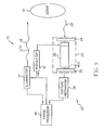
- an SRI camera 10 is shown as a laser radar that is used to illuminate a scene 12 and then to capture an image bundle comprising a minimum of three images of the scene 12.
- An illuminator 14 emits a beam of electromagnetic radiation whose frequency is controlled by a modulator 16.
- the illuminator 14 is a laser device which includes an optical diffuser in order to effect a wide-field illumination.
- the modulator 16 provides an amplitude varying sinusoidal modulation.
- the modulation frequency is sufficiently high (e.g., 12.5 MHz) to attain sufficiently accurate range estimates.
- the output beam 18 is directed toward the scene 12 and a reflected beam 20 is directed back toward a receiving section 22.
- the reflected beam 20 is a delayed version of the transmitted output beam 18, with the amount of phase delay being a function of the distance of the scene 12 from the range imaging system.
- the reflected beam 20 strikes a photocathode 24 within an image intensifier 26, thereby producing a modulated electron stream proportional to the input amplitude variations.
- the purpose of the image intensifier is not only to intensify the image, but also to act as a frequency mixer and shutter. Accordingly, the image intensifier 26 is connected to the modulator 16, causing the gain of a microchannel plate 30 to modulate.
- the electron stream from the photocathode 24 strikes the microchannel plate 30 and is mixed with a modulating signal from the modulator 16.
- the modulated electron stream is amplified through secondary emission by the microchannel plate 30.
- the intensified electron stream bombards a phosphor screen 32, which converts the energy into a visible light image.
- the intensified light image signal is captured by a capture mechanism 34, such as a charge-coupled device (CCD).
- CCD charge-coupled device
- the captured image signal is applied to a range processor 36 to determine the phase delay at each point in the scene.
- phase term ⁇ is not directly accessible from a single image.
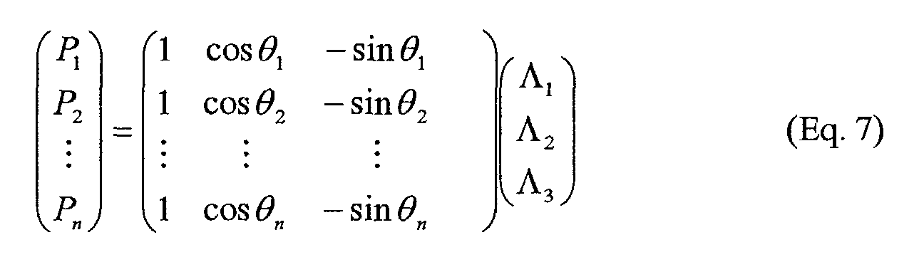
- equation (6) there are three unknown values and the form of the equation is quite simple.
- an image bundle shall be understood to constitute a collection of images which are of the same scene, but with each image having a distinct phase offset obtained from the modulation applied to the intensifier 26.
- an analogous analysis can be performed by phase shifting the illuminator 14 instead of the intensifier 26. If an image bundle comprising more than three images is captured, then the estimates of range can be enhanced by a least squares analysis using a singular value decomposition (see, e.g., W.H. Press, B.P. Flannery, S.A. Teukolsky and W.T. Vetterling, Numerical Recipes (the Art of Scientific Computing ), Cambridge University Press, Cambridge, 1986).
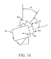
- Figure 10 shows the use of an SRI camera 10 in a panoramic imaging application.
- a single SRI camera 10 is mounted to pivot about a Y-axis (vertical axis) 50 through a number of capture positions 54, each separated by an angle ⁇ that provides an overlapping field of view between neighboring positions.
- the Y-axis 50 is arranged to be coincident with a focal point 50 of the lens 52 of the SRI camera 10. In this manner, a sequence of image inputs are obtained as the SRI camera 10 is rotated around the focal point 50 of the camera lens 52, causing each successive image to slightly overlap its neighboring image.
- each input corresponds to an image bundle
- a plurality of image bundles of the scene are acquired by rotating the SRI camera 10 about its Y-axis (vertical axis) 50, wherein there is an overlap region between adjacent image bundles.
- SRI scannerless range imaging
- the invention may be used in connection with other types of range imaging systems, such as scanned systems, and the claims, unless specifically directed to SRI systems, are intended to read without limitation on any kind of range imaging system.
- the collection of image bundles is the preferred embodiment, it should be understood that the invention is not limited to any specific image collection.
- there may be applications e.g., in creating virtual images of small objects, where the SRI camera may be stationary and the "scene" may be rotated, e.g., on a turntable, in order to obtain overlapping images.
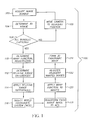
- a image processing method 100 for deriving a three-dimensional panorama from a plurality of image bundles of a scene generated from an SRI camera, including the steps of acquiring an image bundle 102 with the SRI camera, determining a range 104, capturing all image bundles 106, moving the SRI camera to an adjacent position 108, determining a warp function and a registration point 110, determining relative range differences 112, applying the relative range differences 114, selecting a world coordinate system 116, transforming each range image to the world coordinate system 118, warping the images 120, registering the adjacent warped images 122, and forming a 3D panoramic image 124.
- the image processing method 100 forms a complete three-dimensional scene panorama for virtual reality visualization.
- the method 100 uses an image bundle 102 to generate a corresponding spatial image, e.g. an (X,Y,Z) image, in step 104.
- An inquiry of whether all image bundles have been captured is performed 106.
- a negative response to the inquiry causes the SRI camera to move to an adjacent position 108.
- a warping function and registration point is computed 110 and used to determine the differences in constant offsets of the relative 3D range values between image bundles captured from adjacent positions 112. Once these differences have been determined, they are applied to the spatial images 114.
- An arbitrary reference three-dimensional world coordinate system is established in step 116 to uniquely describe the spatial property of the scene captured.
- All the estimated spatial images are transformed in step 118 to the reference three-dimensional world coordinate system with a homogeneous transformation matrix that is constructed based on the information of the capturing device.
- the transformed spatial images are stitched together to form a spatial panorama after a cylindrical warping procedure 120 and a registration process 122.
- the intensity images are stitched together to form an intensity panorama in step 124 after the same procedures. Both spatial and intensity panoramas are used in a virtual display with no further transformation operation needed.
- an image bundle 200 includes a combination of images captured by the SRI system as well as information pertinent to the individual images and information common to all the images.
- the image bundle contains two types of images: range images 202 related to the image capture portion of the SRI process and an intensity image 204, which may be a color image.
- Common information 206 in the image bundle 200 would typically include the number of range images in the bundle (three or more) and the modulation frequency used by the SRI system. Other information might be the number of horizontal and vertical pixels in the images, and/or data related to camera status at the time of the image capture.
- Image specific information will include the phase offset 1...N used for each (1...N) of the individual range images 202.
- the image bundle 200 includes a minimum of three such images, each of which are monochrome.
- the additional intensity image 204 is an image using an optical channel of the SRI camera that does not contain range capture components. For example, as disclosed in the aforementioned Serial No. 09/572,522, which is incorporated herein by reference, a beamsplitter is used to establish two optical paths: one path contains the range imaging elements and the other path contains regular optics for transmitting the intensity (e.g., color) image.
- An optical network (including light control means such as a shutter) recombines the image paths toward a single image responsive element, and a range image and a intensity image are separately, and sequentially, captured.
- the range imaging elements and regular optics may be interchanged in a single optical path.
- the intensity image may be a color image, it is preferably, but not necessarily, the same size as the range images 202.
- an image bundle is used to determine 3D range 104.
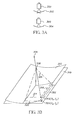
- images captured from a camera 300 are projections of objects through the nodal point of the taking lens into a plane, an inherent distortion exists. Objects near the center of an image appear smaller than objects near the edges; this distortion is evident in regions of overlap between images 302. In order to create a spatial panorama containing no distortion, the intensity images and 3D range images must eventually be warped.
- a cylindrical warp 110 where the images are warped onto a cylinder 304 about the vertical axis of the cylinder.
- This warping technique is described in detail in the aforementioned copending U.S. Patent Application Serial No. 09/383,573, "Method For Creating Environment Map Containing Information Extracted From Stereo Image Pairs", which is incorporated herein by reference. Briefly described, the warp can be described by a function W ( x p ,y p ) that maps pixel 324 ( x p ,y p ) in the image plane 318 to pixel 312 ( x c ,y c ) in the warped plane 310.
- the cylindrical warping function W ( x p ,y p ) can be determined in the following manner; suppose the real world point 306 is projected through the rear nodal point 308 of the taking lens onto the cylinder 304 at point 312 ( x c ,y c ), where x c is the horizontal pixel coordinate 314 and y c is the vertical pixel coordinate 316 (relative to the orthogonal projection of the nodal point 308 onto the image plane 318).
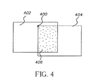
- the registration point 400 of adjacent images 402 and 404 warped by the warping function W must be found.
- Any of a variety of image alignment techniques can be used to register the warped left 402 and right 404 images; e.g., see C. D. Kuglin and D. C. Hines, "The Phase Correlation Image Alignment Method", Proc. 1975 International Conference on Cybernetics and Society, pp. 163-165, 1975, which is incorporated herein by reference.
- the adjacent warped intensity images and the adjacent warped range images may be separately registered, since the coordinates of the range images correspond exactly to those of the intensity images, common values in the adjacent warped intensity images are registered and then registration points in the warped range images are defined to be in the same locations as those used for registering the intensity images.
- the output of the image alignment method yields the overlap region 406 between the left 402 and right 404 warped intensity images.
- the registration point 400 is taken to be the upper left hand comer of the overlap region 406; but, in general, can be defined as any point which identifies the location of the overlap region.
- Figure 5B illustrates the difference in the local coordinate systems that describe the range values in the left 500 and right 502 images. Looking down the nodal axis of the SRI camera, 508 is parallel to the x -axis of the left image 500, and 510 is parallel to the x -axis of the right image 502.
- the real world point 306 projected into both images is found to have a 3D range value 512 of d 1 in the left image 500 and a 3D range value 514 of d 2 in the right image 502.
- the angle 518 between the image planes is known a priori , and is denoted ⁇ .
- Figure 6 describes the process 112 (referred to in Figure 1), whereby an estimate for ⁇ is determined.
- the right hand side of Equation 13 is evaluated, yielding d and 2 , an estimate of the 3D range value in the right image.
- the 3D range images are warped according to the warp function W , and then they are registered using the pre-determined registration point 400.
- the error between the predicted d and 2 values and the actual d 2 values in the overlap region 406 of the warped registered images are computed 606 by calculating the difference d and 2 - d 2 at each pixel, squaring this difference, and then summing the squared difference values for all overlapping pixels.
- the current estimate for ⁇ is chosen to be the relative range difference between the two images. According to 114 (referring to Figure 1), the relative range difference ⁇ is added to each 3D range value in the left image 500. Note that once the relative range difference has been applied, the range values in the left 500 and right 502 images will not be absolute; rather, they will still be relative, but with consistent constant offsets.
- the resulting corrected 3D values are used to form spatial images (X,Y,Z) for the scene.
- the resulting spatial images are valid for a local three-dimensional coordinate system only. That is, for image 500, the (X,Y,Z) values are given with respect to local three-dimensional coordinate system 1 XY 1 Z; for image 502, the 3D values are given with respect to local three-dimensional coordinate system 2 XY 2 Z. If a panoramic image sequence is composed with N pairs of images, there will be N different three-dimensional coordinate systems with respect to which the (X,Y,Z) values are computed.
- Figure 7 includes an example coordinate system transformation 700, a rotation direction 702, a reference coordinate system 704, a pre-transformation (A) coordinate system 706, a pre-transformation (B) coordinate system 708, an angle 710 between coordinate systems 706 and 704, an angle 712 between coordinate systems 708 and 704.
- A pre-transformation
- B pre-transformation
- Figure 8 shows a three-dimensional panoramic imaging system 800, including a panoramic 3D capturing system 802, a reference coordinate system 804, an image stitching system 806, a graphics display system 808, a plurality of intensity (R,G,B) images 810, a plurality of spatial (X,Y,Z) images, a sequence of transformed images 814, a stitched spatial panorama 816, and a stitched intensity panorama 818.
- a panoramic 3D capturing system 802 a reference coordinate system 804
- an image stitching system 806 a graphics display system 808, a plurality of intensity (R,G,B) images 810, a plurality of spatial (X,Y,Z) images, a sequence of transformed images 814, a stitched spatial panorama 816, and a stitched intensity panorama 818.
- the three-dimensional panoramic imaging system 800 enables the 3D panoramic capturing system 802 to produce a sequence of three-dimensional (X,Y,Z) images 812 as well as a sequence of (R,G,B) images 810.
- each of the (X,Y,Z) images generated from the captured sequence is transformed to a common three-dimensional coordinate system 804 from its local three-dimensional coordinate system at which the corresponding (R,G,B) image is taken and the original (X,Y,Z) image is computed.
- the transformed (X,Y,Z) images in a sequence are stitched together in the image stitching system 806 producing a stitched (X,Y,Z) panorama 816.
- the intensity (R,G,B) images are stitched together in the image stitching system 806 producing a (R,G,B) panorama 818.
- the stitched (X,Y,Z) panorama 816 and (R,G,B) panorama 818 are fed to a graphics display system 808 to generate a virtual world.
- a common reference three-dimensional coordinate system i.e. a world coordinate system
- all the (X,Y,Z) values computed for all the image pairs are transformed from their original local three-dimensional coordinate system to the selected world coordinate system.
- the coordinate system 2 XY 2 Z 704 is chosen as the world coordinate system, all data computed are then transformed to the world coordinate system with the method described below.
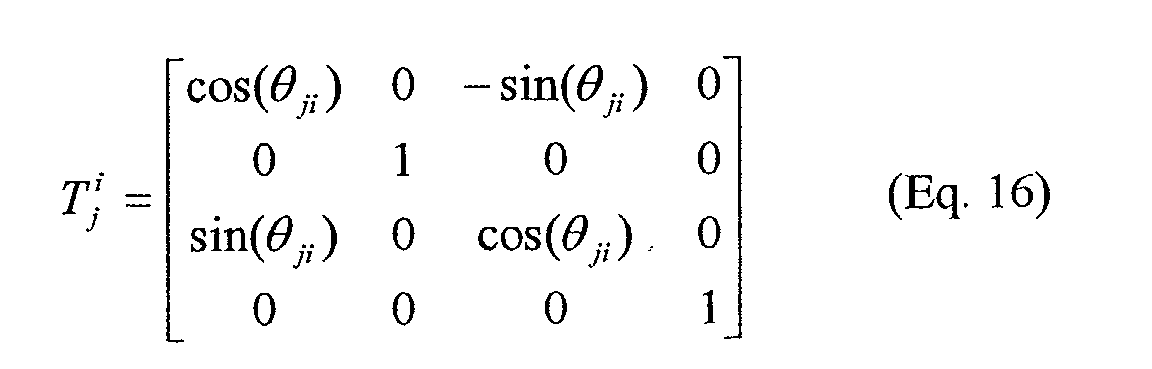
- j P [ j X p , j Y p , j Z p ,1]
- ⁇ ji is the rotation angle from local coordinate system j to world coordinate system i about the Y axis.
- Rotation angles ⁇ , ⁇ , and ⁇ are defined positive if they are counterclockwise when viewed from the positive end of their respective axes.
- Positive rotation angle ⁇ for example, is shown in Fig. 7 as ⁇ 32 710 for transforming coordinate system 3 XY 3 Z 706 to coordinate system 2 XY 2 Z 704. While ⁇ 12 712 is negative since the transformation is made from coordinate system 1 XY 1 Z 708 to coordinate system 1 XY 1 Z 704, which presents a clockwise rotation.
- Arrow 702 indicates the counterclockwise rotation.
- a sequence of transformed (X,Y,Z) images 814 from each of the local three-dimensional coordinate systems to the selected reference three-dimensional world coordinate system is produced.
- the sequence of transformed (X,Y,Z) images ready is stitched together in image stitch block 806 where the sequence of (R,G,B) images is also stitched. Since images are a perspective projection of real world objects onto a plane, an inherent distortion exists.
- the (R,G,B) and corresponding transformed (X,Y,Z) images must be first warped from a planar surface to another domain such as a cylindrical surface. Thus a plurality of warped images may be formed.
- the predetermined warp function W can be used. Then, the pre-identified registration points of adjacent sets of overlapping cylindrically warped (R,G,B) images are used to stitch together the cylindrically warped (R,G,B) images to form a (R,G,B) panorama 818.
- adjacent sets (inter-pair) of overlapping cylindrically warped (X,Y,Z) images can be stitched together to form a (X,Y,Z) panorama 816.
- Both (R,G,B) and (X,Y,Z) panoramas are then input to the graphics display system 808, such as the aforementioned VRML system, for visualization.
- the present invention is preferably practiced in an image processing system including a source of digital images, such as a scanner; a computer programmed to process digital images; and an output device such as a graphics display device, a thermal printer, or an inkjet printer.
- the method of the present invention may be sold as a computer program product including a computer readable storage medium bearing computer code for implementing the steps of the invention.
- Computer readable storage medium may include, for example: magnetic storage media such as a magnetic disc (e.g. a hard disk or a floppy disc) or magnetic tape; optical storage media such as optical disc or optical tape; bar code; solid state electronic storage devices such as random access memory (RAM) or read only memory (ROM); or any other physical device or medium employed to store a computer program.
Landscapes
- Engineering & Computer Science (AREA)
- Physics & Mathematics (AREA)
- General Physics & Mathematics (AREA)
- Theoretical Computer Science (AREA)
- Computer Vision & Pattern Recognition (AREA)
- Multimedia (AREA)
- Signal Processing (AREA)
- Image Processing (AREA)
- Stereoscopic And Panoramic Photography (AREA)
- Testing, Inspecting, Measuring Of Stereoscopic Televisions And Televisions (AREA)
- Processing Or Creating Images (AREA)
Abstract
Description


Claims (3)
- A method for deriving a three-dimensional panorama from a plurality of images of a scene generated by a range imaging camera of the type that produces ambiguities in range information, said method comprising the steps of:(a) acquiring a plurality of adjacent images of the scene, wherein there is an overlap region between the adjacent images and at least some of the adjacent images are range images;(b) providing offset data for the range images in order to recover corrected relative scene spatial information, wherein the step of providing offset data further comprises:(i) detecting a relative range difference between adjacent range images as a constant offset between the adjacent images;(ii) applying the constant offset to at least one of adjacent range images to correct for ambiguities in the relative ranges of the range images, thereby providing corrected range images; and(c) deriving a three-dimensional panorama from the corrected range images.
- The method as claimed in claim 1 wherein scene spatial information is provided as image values in a local three-dimensional coordinate system of each of the images and the step (c) of deriving a three-dimensional panorama comprises the steps of:(i) transforming the image values from each of the local three-dimensional coordinate systems of each of the images to a selected reference three-dimensional world coordinate system, thereby providing transformed range images;(ii) warping the transformed range images onto a cylindrical surface, and forming a plurality of warped range images;(iii) registering adjacent warped range images; and(iv) deriving the three-dimensional panorama using the warped range images.
- The method as claimed in claim 1 wherein the step (i) of detecting a relative range difference between adjacent range images as a constant offset comprises the steps of:(i1) predicting the relative range difference by an estimated constant offset;(i2) warping the range images onto a cylindrical surface using the estimated constant offset, and forming a plurality of warped range images;(i3) registering adjacent warped range images, thereby producing predicted range values;(i4) evaluating any error between the predicted range values and the actual range values in the overlap region;(i5) if the error is unacceptable, using an optimization routine to select another estimated constant offset; and(i6) repeating the steps (i2) through (i5) until the error is acceptable, thereby producing the constant offset.
Applications Claiming Priority (2)
| Application Number | Priority Date | Filing Date | Title |
|---|---|---|---|
| US09/803,802 US7194112B2 (en) | 2001-03-12 | 2001-03-12 | Three dimensional spatial panorama formation with a range imaging system |
| US803802 | 2001-03-12 |
Publications (2)
| Publication Number | Publication Date |
|---|---|
| EP1241898A2 true EP1241898A2 (en) | 2002-09-18 |
| EP1241898A3 EP1241898A3 (en) | 2004-08-18 |
Family
ID=25187458
Family Applications (1)
| Application Number | Title | Priority Date | Filing Date |
|---|---|---|---|
| EP02075795A Withdrawn EP1241898A3 (en) | 2001-03-12 | 2002-02-28 | Method for generating panoramic images from a plurality of images |
Country Status (4)
| Country | Link |
|---|---|
| US (1) | US7194112B2 (en) |
| EP (1) | EP1241898A3 (en) |
| JP (1) | JP2002366948A (en) |
| IL (1) | IL147768A0 (en) |
Cited By (2)
| Publication number | Priority date | Publication date | Assignee | Title |
|---|---|---|---|---|
| WO2008067197A2 (en) | 2006-11-17 | 2008-06-05 | Microsoft Corporation | Swarm imaging |
| CN103770706A (en) * | 2012-10-19 | 2014-05-07 | 通用汽车环球科技运作有限责任公司 | Dynamic rearview mirror display features |
Families Citing this family (76)
| Publication number | Priority date | Publication date | Assignee | Title |
|---|---|---|---|---|
| US7400782B2 (en) * | 2002-08-28 | 2008-07-15 | Arcsoft, Inc. | Image warping correction in forming 360 degree panoramic images |
| US8655051B2 (en) * | 2003-01-31 | 2014-02-18 | Fujitsu Limited | Image editing method, image editing apparatus, computer program, and memory product |
| US20040196282A1 (en) * | 2003-02-14 | 2004-10-07 | Oh Byong Mok | Modeling and editing image panoramas |
| JP4144377B2 (en) * | 2003-02-28 | 2008-09-03 | ソニー株式会社 | Image processing apparatus and method, recording medium, and program |
| US8064684B2 (en) * | 2003-04-16 | 2011-11-22 | Massachusetts Institute Of Technology | Methods and apparatus for visualizing volumetric data using deformable physical object |
| JP4325877B2 (en) * | 2004-06-03 | 2009-09-02 | 独立行政法人科学技術振興機構 | High-speed and high-precision singular value decomposition method, program, and apparatus for matrix |
| US20060069591A1 (en) * | 2004-09-29 | 2006-03-30 | Razzano Michael R | Dental image charting system and method |
| JP3882005B2 (en) * | 2005-03-02 | 2007-02-14 | 松下電器産業株式会社 | Image generation method, object detection method, object detection apparatus, and image generation program |
| JP2006270676A (en) * | 2005-03-25 | 2006-10-05 | Fujitsu Ltd | Panorama image generation program, panorama image generation apparatus, and panorama image generation method |
| US20070035542A1 (en) * | 2005-07-27 | 2007-02-15 | Mediapod Llc | System, apparatus, and method for capturing and screening visual images for multi-dimensional display |
| KR20080064864A (en) * | 2005-10-16 | 2008-07-09 | 미디어팟 엘엘씨 | Apparatus, Systems and Methods for Increasing the Quality of Digital Image Capture |
| KR100653200B1 (en) * | 2006-01-09 | 2006-12-05 | 삼성전자주식회사 | Method and device for providing panoramic image by calibrating geometric information |
| US7698014B2 (en) * | 2006-01-20 | 2010-04-13 | 3M Innovative Properties Company | Local enforcement of accuracy in fabricated models |
| US7840042B2 (en) | 2006-01-20 | 2010-11-23 | 3M Innovative Properties Company | Superposition for visualization of three-dimensional data acquisition |
| TWI303782B (en) * | 2006-03-10 | 2008-12-01 | Sony Taiwan Ltd | An optimized video stitching mehtod for asic implementation |
| US7778491B2 (en) * | 2006-04-10 | 2010-08-17 | Microsoft Corporation | Oblique image stitching |
| US7773126B1 (en) * | 2006-05-26 | 2010-08-10 | Itt Manufacturing Enterprises, Inc. | Mosaic image collector including an embedded atomic clock |
| KR100725053B1 (en) * | 2006-06-22 | 2007-06-08 | 삼성전자주식회사 | Panoramic photographing device and method of portable terminal |
| JP4872525B2 (en) * | 2006-08-14 | 2012-02-08 | カシオ計算機株式会社 | Projector, projector distance measurement method, projector projection plane tilt acquisition method, and program |
| KR101264804B1 (en) * | 2006-08-16 | 2013-05-15 | 삼성전자주식회사 | panorama photography method and apparatus capable of informing optimum position of photographing |
| EP2100273A2 (en) | 2006-11-13 | 2009-09-16 | Everyscape, Inc | Method for scripting inter-scene transitions |
| US8208129B2 (en) * | 2007-01-14 | 2012-06-26 | Microsoft International Holdings B.V. | Method, device and system for imaging |
| JP2009077363A (en) * | 2007-08-24 | 2009-04-09 | Sony Corp | Image processing apparatus, moving image reproduction apparatus, processing method and program therefor |
| US7961224B2 (en) * | 2008-01-25 | 2011-06-14 | Peter N. Cheimets | Photon counting imaging system |
| US20090232415A1 (en) * | 2008-03-13 | 2009-09-17 | Microsoft Corporation | Platform for the production of seamless orthographic imagery |
| US8737721B2 (en) | 2008-05-07 | 2014-05-27 | Microsoft Corporation | Procedural authoring |
| US8355042B2 (en) | 2008-10-16 | 2013-01-15 | Spatial Cam Llc | Controller in a camera for creating a panoramic image |
| US8160391B1 (en) * | 2008-06-04 | 2012-04-17 | Google Inc. | Panoramic image fill |
| US8204299B2 (en) * | 2008-06-12 | 2012-06-19 | Microsoft Corporation | 3D content aggregation built into devices |
| US8724007B2 (en) | 2008-08-29 | 2014-05-13 | Adobe Systems Incorporated | Metadata-driven method and apparatus for multi-image processing |
| US8368773B1 (en) | 2008-08-29 | 2013-02-05 | Adobe Systems Incorporated | Metadata-driven method and apparatus for automatically aligning distorted images |
| US8842190B2 (en) | 2008-08-29 | 2014-09-23 | Adobe Systems Incorporated | Method and apparatus for determining sensor format factors from image metadata |
| US8391640B1 (en) * | 2008-08-29 | 2013-03-05 | Adobe Systems Incorporated | Method and apparatus for aligning and unwarping distorted images |
| US8340453B1 (en) | 2008-08-29 | 2012-12-25 | Adobe Systems Incorporated | Metadata-driven method and apparatus for constraining solution space in image processing techniques |
| US8970690B2 (en) * | 2009-02-13 | 2015-03-03 | Metaio Gmbh | Methods and systems for determining the pose of a camera with respect to at least one object of a real environment |
| US20100304720A1 (en) * | 2009-05-27 | 2010-12-02 | Nokia Corporation | Method and apparatus for guiding media capture |
| CN101577795A (en) * | 2009-06-17 | 2009-11-11 | 深圳华为通信技术有限公司 | Method and device for realizing real-time viewing of panoramic picture |
| JP5418127B2 (en) * | 2009-10-09 | 2014-02-19 | ソニー株式会社 | Image processing apparatus and method, and program |
| JP2011166264A (en) * | 2010-02-05 | 2011-08-25 | Sony Corp | Image processing apparatus, imaging device and image processing method, and program |
| US20110242271A1 (en) * | 2010-03-31 | 2011-10-06 | Google Inc. | Synthesizing Panoramic Three-Dimensional Images |
| CN102959943B (en) | 2010-06-24 | 2016-03-30 | 富士胶片株式会社 | Stereoscopic panoramic image synthesizer and method and image capture apparatus |
| US8768101B1 (en) * | 2010-06-30 | 2014-07-01 | The United States Of America As Represented By The Secretary Of The Air Force | Target image registration and fusion |
| CN102972035A (en) | 2010-06-30 | 2013-03-13 | 富士胶片株式会社 | Stereoscopic panorama image synthesizing device and compound-eye imaging device as well as stereoscopic panorama image synthesizing method |
| KR20120046802A (en) * | 2010-10-27 | 2012-05-11 | 삼성전자주식회사 | Apparatus and method of creating 3 dimension panorama image by using a camera |
| US8548269B2 (en) | 2010-12-17 | 2013-10-01 | Microsoft Corporation | Seamless left/right views for 360-degree stereoscopic video |
| JP2012199752A (en) * | 2011-03-22 | 2012-10-18 | Sony Corp | Image processing apparatus, image processing method, and program |
| KR101776702B1 (en) * | 2011-03-25 | 2017-09-08 | 한화테크윈 주식회사 | Monitoring camera for generating 3 dimensional scene and method thereof |
| KR101685418B1 (en) | 2011-04-27 | 2016-12-12 | 한화테크윈 주식회사 | Monitoring system for generating 3-dimensional picture |
| PL2715449T3 (en) | 2011-05-31 | 2017-06-30 | Nokia Technologies Oy | Methods, apparatuses and computer program products for generating panoramic images using depth map data |
| US20130212538A1 (en) * | 2011-08-19 | 2013-08-15 | Ghislain LEMIRE | Image-based 3d environment emulator |
| WO2013033787A1 (en) * | 2011-09-07 | 2013-03-14 | Commonwealth Scientific And Industrial Research Organisation | System and method for three-dimensional surface imaging |
| JP6009753B2 (en) * | 2011-10-26 | 2016-10-19 | 株式会社トプコン | Image measuring device |
| US20130106990A1 (en) | 2011-11-01 | 2013-05-02 | Microsoft Corporation | Planar panorama imagery generation |
| US9324184B2 (en) | 2011-12-14 | 2016-04-26 | Microsoft Technology Licensing, Llc | Image three-dimensional (3D) modeling |
| US9406153B2 (en) | 2011-12-14 | 2016-08-02 | Microsoft Technology Licensing, Llc | Point of interest (POI) data positioning in image |
| US10008021B2 (en) | 2011-12-14 | 2018-06-26 | Microsoft Technology Licensing, Llc | Parallax compensation |
| US9147102B2 (en) * | 2012-01-02 | 2015-09-29 | Camtek Ltd. | Method and system for measuring bumps based on phase and amplitude information |
| US9124801B2 (en) * | 2012-07-26 | 2015-09-01 | Omnivision Technologies, Inc. | Image processing system and method using multiple imagers for providing extended view |
| US9330484B2 (en) * | 2012-08-02 | 2016-05-03 | Here Global B.V. | Plane panorama location correction in three-dimensional mapping |
| CN103970518B (en) * | 2013-01-31 | 2019-06-25 | 腾讯科技(深圳)有限公司 | A kind of the 3D rendering method and device of window logic |
| US9269187B2 (en) | 2013-03-20 | 2016-02-23 | Siemens Product Lifecycle Management Software Inc. | Image-based 3D panorama |
| WO2014178047A1 (en) | 2013-04-30 | 2014-11-06 | Inuitive Ltd. | System and method for video conferencing |
| EP3005232A4 (en) * | 2013-05-29 | 2017-03-15 | Kang-Huai Wang | Reconstruction of images from an in vivo multi-camera capsule |
| US9292913B2 (en) | 2014-01-31 | 2016-03-22 | Pictometry International Corp. | Augmented three dimensional point collection of vertical structures |
| JP2015186170A (en) * | 2014-03-26 | 2015-10-22 | ソニー株式会社 | Image processing apparatus and image processing method |
| JP2017208619A (en) * | 2016-05-16 | 2017-11-24 | 株式会社リコー | Image processing apparatus, image processing method, program and imaging system |
| US10560678B2 (en) * | 2016-11-09 | 2020-02-11 | Mediatek Inc. | Method and apparatus having video encoding function with syntax element signaling of rotation information of content-oriented rotation applied to 360-degree image content or 360-degree video content represented in projection format and associated method and apparatus having video decoding function |
| US10917626B2 (en) * | 2016-11-23 | 2021-02-09 | Microsoft Technology Licensing, Llc | Active illumination 3D imaging system |
| IT201700009585A1 (en) * | 2017-01-30 | 2018-07-30 | The Edge Company S R L | METHOD FOR RECOGNIZING OBJECTS FOR ENGINES OF REALITY INCREASED BY AN ELECTRONIC DEVICE |
| US10901073B2 (en) | 2017-07-11 | 2021-01-26 | Microsoft Technology Licensing, Llc | Illumination for zoned time-of-flight imaging |
| US10430958B2 (en) | 2017-07-11 | 2019-10-01 | Microsoft Technology Licensing, Llc | Active illumination 3D zonal imaging system |
| CN111354044B (en) * | 2020-02-28 | 2023-04-21 | 上海科技大学 | A panoramic visual compass estimation method based on sinusoidal curve fitting and its application |
| CN111462311B (en) * | 2020-03-31 | 2023-10-24 | 北京小米松果电子有限公司 | Panorama generation method and device, storage medium |
| KR102441485B1 (en) * | 2020-05-29 | 2022-09-07 | 주식회사 메디트 | METHOD AND APPARATUS FOR OBTAINING THREE Dimensional Data AND COMPUTER READABLE MEDIUM STORING A PROGRAM FOR PERFORMING THE SAME METHOD |
| US11615582B2 (en) * | 2021-06-08 | 2023-03-28 | Fyusion, Inc. | Enclosed multi-view visual media representation |
| CN114022386B (en) * | 2021-11-07 | 2024-11-19 | 桂林电子科技大学 | An image restoration method based on Helmholtz-Hodge decomposition |
Family Cites Families (11)
| Publication number | Priority date | Publication date | Assignee | Title |
|---|---|---|---|---|
| US4935616A (en) * | 1989-08-14 | 1990-06-19 | The United States Of America As Represented By The Department Of Energy | Range imaging laser radar |
| US5796386A (en) * | 1995-01-23 | 1998-08-18 | International Business Machines Corporation | Precise calibration procedure for sensor-based view point control system |
| US6044181A (en) * | 1997-08-01 | 2000-03-28 | Microsoft Corporation | Focal length estimation method and apparatus for construction of panoramic mosaic images |
| US6011558A (en) * | 1997-09-23 | 2000-01-04 | Industrial Technology Research Institute | Intelligent stitcher for panoramic image-based virtual worlds |
| US6023588A (en) * | 1998-09-28 | 2000-02-08 | Eastman Kodak Company | Method and apparatus for capturing panoramic images with range data |
| US6118946A (en) * | 1999-06-29 | 2000-09-12 | Eastman Kodak Company | Method and apparatus for scannerless range image capture using photographic film |
| US6542249B1 (en) * | 1999-07-20 | 2003-04-01 | The University Of Western Ontario | Three-dimensional measurement method and apparatus |
| US6288776B1 (en) * | 1999-11-24 | 2001-09-11 | Eastman Kodak Company | Method for unambiguous range estimation |
| US6349174B1 (en) * | 2000-05-17 | 2002-02-19 | Eastman Kodak Company | Method and apparatus for a color scannerless range imaging system |
| US6456793B1 (en) * | 2000-08-03 | 2002-09-24 | Eastman Kodak Company | Method and apparatus for a color scannerless range imaging system |
| US6754370B1 (en) * | 2000-08-14 | 2004-06-22 | The Board Of Trustees Of The Leland Stanford Junior University | Real-time structured light range scanning of moving scenes |
-
2001
- 2001-03-12 US US09/803,802 patent/US7194112B2/en not_active Expired - Lifetime
-
2002
- 2002-01-22 IL IL14776802A patent/IL147768A0/en unknown
- 2002-02-28 EP EP02075795A patent/EP1241898A3/en not_active Withdrawn
- 2002-03-11 JP JP2002064983A patent/JP2002366948A/en active Pending
Cited By (6)
| Publication number | Priority date | Publication date | Assignee | Title |
|---|---|---|---|---|
| WO2008067197A2 (en) | 2006-11-17 | 2008-06-05 | Microsoft Corporation | Swarm imaging |
| EP2098065A4 (en) * | 2006-11-17 | 2012-04-04 | Microsoft Corp | IMAGING BY ESSAIM |
| US8498497B2 (en) | 2006-11-17 | 2013-07-30 | Microsoft Corporation | Swarm imaging |
| US9042677B2 (en) | 2006-11-17 | 2015-05-26 | Microsoft Technology Licensing, Llc | Swarm imaging |
| CN103770706A (en) * | 2012-10-19 | 2014-05-07 | 通用汽车环球科技运作有限责任公司 | Dynamic rearview mirror display features |
| CN103770706B (en) * | 2012-10-19 | 2016-03-23 | 通用汽车环球科技运作有限责任公司 | Dynamic reversing mirror indicating characteristic |
Also Published As
| Publication number | Publication date |
|---|---|
| US7194112B2 (en) | 2007-03-20 |
| US20020154812A1 (en) | 2002-10-24 |
| JP2002366948A (en) | 2002-12-20 |
| IL147768A0 (en) | 2002-08-14 |
| EP1241898A3 (en) | 2004-08-18 |
Similar Documents
| Publication | Publication Date | Title |
|---|---|---|
| US7194112B2 (en) | Three dimensional spatial panorama formation with a range imaging system | |
| US7010158B2 (en) | Method and apparatus for three-dimensional scene modeling and reconstruction | |
| US6677982B1 (en) | Method for three dimensional spatial panorama formation | |
| US7342669B2 (en) | Three-dimensional shape measuring method and its device | |
| US6507665B1 (en) | Method for creating environment map containing information extracted from stereo image pairs | |
| KR100513055B1 (en) | 3D scene model generation apparatus and method through the fusion of disparity map and depth map | |
| JP2874710B2 (en) | 3D position measuring device | |
| US7015951B1 (en) | Picture generating apparatus and picture generating method | |
| US20120275688A1 (en) | Method for automated 3d imaging | |
| JP2004515832A (en) | Apparatus and method for spatio-temporal normalization matching of image sequence | |
| WO2012141235A1 (en) | Three-dimensional point group position data processing device, three-dimensional point group position data processing system, three-dimensional point group position data processing method and program | |
| JP2003203238A (en) | Scalable architecture that supports many video streams at frame rate | |
| US6349174B1 (en) | Method and apparatus for a color scannerless range imaging system | |
| CN113965721B (en) | Alignment method of image and depth transmission surveillance system | |
| EP3845922A1 (en) | Calibration system for combined depth and texture sensor | |
| Cai et al. | Visual Expansion and Real‐Time Calibration for Pan‐Tilt‐Zoom Cameras Assisted by Panoramic Models | |
| Partovi et al. | Automatic integration of laser scanning and photogrammetric point clouds: From acquisition to co-registration | |
| JP3912638B2 (en) | 3D image processing device | |
| US6856382B2 (en) | Formation of three-dimensional video sequences with a scannerless range imaging system | |
| Guan et al. | A unified approach to calibrate a network of camcorders and tof cameras | |
| Schiller et al. | Increasing realism and supporting content planning for dynamic scenes in a mixed reality system incorporating a time-of-flight camera | |
| Amini et al. | Development of a new stereo‐panorama system based on off‐the‐shelf stereo cameras | |
| JP2004340714A (en) | Optimum arrangement determination method of stereo camera and its system | |
| JP2006078291A (en) | Omnidirectional three-dimensional measuring device | |
| Helala et al. | Mosaic of near ground UAV videos under parallax effects |
Legal Events
| Date | Code | Title | Description |
|---|---|---|---|
| PUAI | Public reference made under article 153(3) epc to a published international application that has entered the european phase |
Free format text: ORIGINAL CODE: 0009012 |
|
| AK | Designated contracting states |
Kind code of ref document: A2 Designated state(s): AT BE CH CY DE DK ES FI FR GB GR IE IT LI LU MC NL PT SE TR |
|
| AX | Request for extension of the european patent |
Free format text: AL;LT;LV;MK;RO;SI |
|
| PUAL | Search report despatched |
Free format text: ORIGINAL CODE: 0009013 |
|
| AK | Designated contracting states |
Kind code of ref document: A3 Designated state(s): AT BE CH CY DE DK ES FI FR GB GR IE IT LI LU MC NL PT SE TR |
|
| AX | Request for extension of the european patent |
Extension state: AL LT LV MK RO SI |
|
| AKX | Designation fees paid | ||
| REG | Reference to a national code |
Ref country code: DE Ref legal event code: 8566 |
|
| DBV | Designated contracting states (deleted) | ||
| STAA | Information on the status of an ep patent application or granted ep patent |
Free format text: STATUS: THE APPLICATION IS DEEMED TO BE WITHDRAWN |
|
| 18D | Application deemed to be withdrawn |
Effective date: 20050219 |