EP1241532A2 - Image forming apparatus, control method thereof and control program therefor - Google Patents
Image forming apparatus, control method thereof and control program therefor Download PDFInfo
- Publication number
- EP1241532A2 EP1241532A2 EP02005926A EP02005926A EP1241532A2 EP 1241532 A2 EP1241532 A2 EP 1241532A2 EP 02005926 A EP02005926 A EP 02005926A EP 02005926 A EP02005926 A EP 02005926A EP 1241532 A2 EP1241532 A2 EP 1241532A2
- Authority
- EP
- European Patent Office
- Prior art keywords
- discharge
- setting
- recording
- image forming
- sheet
- Prior art date
- Legal status (The legal status is an assumption and is not a legal conclusion. Google has not performed a legal analysis and makes no representation as to the accuracy of the status listed.)
- Granted
Links
Images










Classifications
-
- G—PHYSICS
- G03—PHOTOGRAPHY; CINEMATOGRAPHY; ANALOGOUS TECHNIQUES USING WAVES OTHER THAN OPTICAL WAVES; ELECTROGRAPHY; HOLOGRAPHY
- G03G—ELECTROGRAPHY; ELECTROPHOTOGRAPHY; MAGNETOGRAPHY
- G03G15/00—Apparatus for electrographic processes using a charge pattern
- G03G15/65—Apparatus which relate to the handling of copy material
- G03G15/6588—Apparatus which relate to the handling of copy material characterised by the copy material, e.g. postcards, large copies, multi-layered materials, coloured sheet material
- G03G15/6594—Apparatus which relate to the handling of copy material characterised by the copy material, e.g. postcards, large copies, multi-layered materials, coloured sheet material characterised by the format or the thickness, e.g. endless forms
-
- G—PHYSICS
- G03—PHOTOGRAPHY; CINEMATOGRAPHY; ANALOGOUS TECHNIQUES USING WAVES OTHER THAN OPTICAL WAVES; ELECTROGRAPHY; HOLOGRAPHY
- G03G—ELECTROGRAPHY; ELECTROPHOTOGRAPHY; MAGNETOGRAPHY
- G03G15/00—Apparatus for electrographic processes using a charge pattern
- G03G15/65—Apparatus which relate to the handling of copy material
- G03G15/6588—Apparatus which relate to the handling of copy material characterised by the copy material, e.g. postcards, large copies, multi-layered materials, coloured sheet material
- G03G15/6591—Apparatus which relate to the handling of copy material characterised by the copy material, e.g. postcards, large copies, multi-layered materials, coloured sheet material characterised by the recording material, e.g. plastic material, OHP, ceramics, tiles, textiles
-
- G—PHYSICS
- G03—PHOTOGRAPHY; CINEMATOGRAPHY; ANALOGOUS TECHNIQUES USING WAVES OTHER THAN OPTICAL WAVES; ELECTROGRAPHY; HOLOGRAPHY
- G03G—ELECTROGRAPHY; ELECTROPHOTOGRAPHY; MAGNETOGRAPHY
- G03G2215/00—Apparatus for electrophotographic processes
- G03G2215/00362—Apparatus for electrophotographic processes relating to the copy medium handling
- G03G2215/00443—Copy medium
- G03G2215/00451—Paper
- G03G2215/00464—Non-standard format
-
- G—PHYSICS
- G03—PHOTOGRAPHY; CINEMATOGRAPHY; ANALOGOUS TECHNIQUES USING WAVES OTHER THAN OPTICAL WAVES; ELECTROGRAPHY; HOLOGRAPHY
- G03G—ELECTROGRAPHY; ELECTROPHOTOGRAPHY; MAGNETOGRAPHY
- G03G2215/00—Apparatus for electrophotographic processes
- G03G2215/00362—Apparatus for electrophotographic processes relating to the copy medium handling
- G03G2215/00443—Copy medium
- G03G2215/00451—Paper
- G03G2215/00476—Non-standard property
- G03G2215/00481—Thick
-
- G—PHYSICS
- G03—PHOTOGRAPHY; CINEMATOGRAPHY; ANALOGOUS TECHNIQUES USING WAVES OTHER THAN OPTICAL WAVES; ELECTROGRAPHY; HOLOGRAPHY
- G03G—ELECTROGRAPHY; ELECTROPHOTOGRAPHY; MAGNETOGRAPHY
- G03G2215/00—Apparatus for electrophotographic processes
- G03G2215/00362—Apparatus for electrophotographic processes relating to the copy medium handling
- G03G2215/00443—Copy medium
- G03G2215/00451—Paper
- G03G2215/00476—Non-standard property
- G03G2215/00485—Thin
-
- G—PHYSICS
- G03—PHOTOGRAPHY; CINEMATOGRAPHY; ANALOGOUS TECHNIQUES USING WAVES OTHER THAN OPTICAL WAVES; ELECTROGRAPHY; HOLOGRAPHY
- G03G—ELECTROGRAPHY; ELECTROPHOTOGRAPHY; MAGNETOGRAPHY
- G03G2215/00—Apparatus for electrophotographic processes
- G03G2215/00362—Apparatus for electrophotographic processes relating to the copy medium handling
- G03G2215/00443—Copy medium
- G03G2215/00493—Plastic
- G03G2215/00497—Overhead Transparency, i.e. OHP
-
- G—PHYSICS
- G03—PHOTOGRAPHY; CINEMATOGRAPHY; ANALOGOUS TECHNIQUES USING WAVES OTHER THAN OPTICAL WAVES; ELECTROGRAPHY; HOLOGRAPHY
- G03G—ELECTROGRAPHY; ELECTROPHOTOGRAPHY; MAGNETOGRAPHY
- G03G2215/00—Apparatus for electrophotographic processes
- G03G2215/00362—Apparatus for electrophotographic processes relating to the copy medium handling
- G03G2215/00789—Adding properties or qualities to the copy medium
- G03G2215/00818—Punch device
-
- G—PHYSICS
- G03—PHOTOGRAPHY; CINEMATOGRAPHY; ANALOGOUS TECHNIQUES USING WAVES OTHER THAN OPTICAL WAVES; ELECTROGRAPHY; HOLOGRAPHY
- G03G—ELECTROGRAPHY; ELECTROPHOTOGRAPHY; MAGNETOGRAPHY
- G03G2215/00—Apparatus for electrophotographic processes
- G03G2215/00362—Apparatus for electrophotographic processes relating to the copy medium handling
- G03G2215/00789—Adding properties or qualities to the copy medium
- G03G2215/00822—Binder, e.g. glueing device
-
- G—PHYSICS
- G03—PHOTOGRAPHY; CINEMATOGRAPHY; ANALOGOUS TECHNIQUES USING WAVES OTHER THAN OPTICAL WAVES; ELECTROGRAPHY; HOLOGRAPHY
- G03G—ELECTROGRAPHY; ELECTROPHOTOGRAPHY; MAGNETOGRAPHY
- G03G2215/00—Apparatus for electrophotographic processes
- G03G2215/00362—Apparatus for electrophotographic processes relating to the copy medium handling
- G03G2215/00789—Adding properties or qualities to the copy medium
- G03G2215/00877—Folding device
Definitions
- the present invention relates to an image forming apparatus for conveying a sheet into image forming means of a predetermined method, conducting image formation by such image forming means and then discharging the sheet from a discharge path, and a control method thereof and a control program therefor.
- the image forming apparatus has conventionally been supplied principally as a single-function apparatus such as a facsimile apparatus, a copying machine or a printers as a computer peripheral, but is recently available also in so-called digital composite apparatus in which the printer is combined with a scanner for image reading, a facsimile function and/or a communicating function through a LAN.
- the functions are highly diversified and there are often required various functions such as a function of, after recording, classifying and discharging the sheets to the respectively different plural discharge trays, for example, for copying, for a PC printer, for facsimile, etc., a finisher function of executing highly diversified post-treatments such as bookbinding or Z-folding, a function of recording on special paper such as a thick papers (or cardboard) or an OHP sheet and then discharging the paper.
- an image forming apparatus provided with first reception means for receiving print data from an external terminal, reading means for reading an image and outputting read print data, and recording means for recording an image on a recording medium based on the received or read print data, characterized by comprising discrimination means for discriminating whether the reception is made either from the first reception means or reading means, first sheet discharge means and second sheet discharge means for discharging the recording medium recorded by the recording means, sheet discharge setting means for setting whether to discharge the recording medium to the first sheet discharge means or to the second sheet discharge means respectively corresponding to the first reception means and the reading means, wherein the first discharge means is positioned between the reading means and the recording means and the second discharge means is so positioned as to be connectable to a post-treatment apparatus and to execute discharge to the exterior of the image forming apparatus, selection means for selecting either the first discharge means or the second discharge means, special paper setting means for setting special paper as the type of the recording medium to be recorded by the recording means, post-
- an image forming apparatus controlling program for controlling, from a remote external information processing terminal, an image forming apparatus provided with first reception means for receiving print data from an external terminal, reading means for reading an image and outputting read print data, and recording means for recording an image on a recording medium based on the received or read data, and further including discrimination means for discriminating whether the reception is made either from the first reception means or the reading means, first discharge means and second discharge means for discharging the recording medium recorded by the recording means, and sheet discharge setting means for setting whether to discharge the recording medium to the first discharge means or to the second discharge means respectively corresponding to the first reception means and the reading means, wherein the first discharge means is positioned between the reading means and the recording means and the second sheet discharge means is connectable to a post-treatment apparatus and is so positioned as to discharge the recording medium to the exterior of the apparatus, and selection means for selecting the first discharge means or the second discharge means.
- the program comprises a special paper setting step for setting special paper as the type of the recording medium, and a post-treatment setting step for setting post-treatment after recording by the recording means, wherein the special sheet setting means and the post-treatment setting means are selected in exclusive manner.
- the functions that can only be utilized in exclusive manner are controlled in exclusive manner in an operation program for control from the operation unit of the apparatus or from a PC or the like distant from the apparatus.
- Fig. 1 schematically shows the hardware configuration of a digital composite apparatus embodying the present invention, principally showing the configuration of a sheet conveying system in an image reading system and an image recording system.
- an electrophotographic recording unit 1 an original table 2 for reading an original, and an automatic original feeding unit 3 for feeding the original to a reading position.
- the original table 2 is also provided with an unrepresented operation unit.
- sheet cassette 11, 12, 13 for feeding recording sheets
- conveying path 14 for conveying the sheet fed from the sheet cassettes 11 to 13, and a manual sheet insertion unit 15.
- a conveying path 16 for guiding the sheet, fed from the sheet cassettes 11 to 13 or the manual sheet insertion unit 15, to an image forming unit (17, 18, 19, 20), a laser unit 17 for receiving an image signal and generating laser light corresponding to the image signal, a latent image forming drum 18 for generating a latent image based on the generated laser light, a transfer roller 19 for transferring a toner image, formed by developing the latent image formed on the latent image forming drum 18, onto a sheet, and thermal fixation rollers 20 for fixing the image transferred onto the sheet by the transfer roller 19.
- the first discharge path 22 has a smaller curvature (in general, reciprocal of the radius of curvature, the curving being less for a smaller curvature) than in the second and third discharge paths 23, 24. This is because, as the original table 2 is positioned in the upper part, the apparatus inevitably becomes bulky and the convenience of use thereof (original handling on the original table 2 or operability of the operation unit) is deteriorated if the curvature of the conveying path is made smaller (if the curving is made milder) in the second and third discharge paths 23, 24.
- the first discharge path 22 of the smaller curvature can pass the sheet of various types (special papers) such as cardboard (or thick paper), thin paper, postcard, free-size sheet, etc. (stated differently, such special paper can only be discharged from the first discharge path 22).
- special papers such as cardboard (or thick paper), thin paper, postcard, free-size sheet, etc.
- the second and third discharge paths, having a larger curvature is not suitable for passing the special paper but is suitable for discharging the ordinary paper.
- the installation area (footprint) of the apparatus can be made smaller by positioning the second discharge path above the first discharge path.
- the dual-side path 25 for recording on both sides of the sheet is provided with plural rollers and is so constructed as to invert and re-feed a sheet of which one side was subjected to the recording, by the laser unit 17, the latent image forming drum 18, the transfer roller 19 and the thermal fixation roller 20.
- a finisher 26 is rendered connectable to the second discharge path 23 and the third discharge path 24.
- the finisher 26 is formed compact since the original table 2 is positioned in the upper part and has limited functions such as tray shifting, stapling, etc.
- a finisher 27 connectable to the third sheet discharge path can be of a large size and can have multiple functions since it is not dimensionally limited in the upper or lower part. Thus, there can be realized such functions as stapling, Z-folding, book binding, punching, etc.
- Such arrangement of the third discharge path allows to limit the height of the apparatus and to improve the convenience of use of the apparatus (original handling on the original table 2 or operability of the operation unit).
- the two finishers 26, 27 need not be both connected, but may be sold as optional units according to the desire of the customer.
- the finisher 26 is supplied to a user who does not desire a large installation area of the apparatus, while the finisher 27 is supplied to a user who wishes a finisher of high performance even if the size thereof is large.
- the first discharge path 22 is always used even in case neither of the finishers 26, 27 are connected, so that at least the first discharge path 22 is so constructed as to be capable of passing the sheet of various types (cardboard, thin paper, postcard, free-size sheet, etc.).
- Such configuration provides the following advantages in case an existing printer is utilized for constructing a composite apparatus as in the present embodiment by attaching a scanner, an operation unit, a sheet discharge section, etc.
- the apparatus can be easily constructed by merely attaching a second discharge path, simply utilizing the first discharge path capable of passing the sheet of various types in the original existing printer. Also there is obtained an advantage that the first discharge path 22, being shortest sheet conveying path, least damages the sheet.
- the present apparatus is constructed as a digital composite apparatus and is rendered capable of being utilized as a printer or a scanner of a client terminal on a LAN, also recording data or outputting a copy of facsimile data or the like received through a public line. Therefore, the apparatus has such a configuration capable of setting the discharge path for the recorded print of the printer, facsimile or copying operation respectively from one of the first to third discharge paths.
- an original P In the original table 2 shown in the upper part of Fig. 1, there are shown an original P, an original tray 31, an original conveying path 32, an original 33 of which the rear surface is to be read, an original discharge path 34 for reading the original in conveying motion and discharging such original onto an original discharge tray, an original discharge tray 36 for stacking the read originals, an original support table 35 for reading a book-type original, mirrors 37, 38, 39 for guiding the light reflected from the original to a reading sensor 40, and the reading sensor 40 comprises a reading element composed of a CCD for photoelectric conversion of the light reflected from the original.
- the distance A from the bottom face of the apparatus to the dual-side path is 443 mm
- the height B in the dual-side path is 34 mm
- the distance C from the dual-side path to the position of the fixing rollers is 80 mm
- the distance D from the bottom face of the apparatus to the starting position of curvature of the first discharge path is 723 mm
- the distance E from the bottom face of the apparatus to the original table (operation unit) is 970 mm. It is empirically known that the height of the operation unit or the original table is desirably about 970 mm in consideration of the operability.
- the height difference F between the start position of curvature of the first discharge path and the discharge position thereof is selected as 72 mm
- the height difference G between the start position of curvature of the second discharge path and the discharge position thereof is selected as 42 mm
- the height difference H between the discharge positions of the first and second discharge paths is 87.5 mm.
- Fig. 2 shows the configuration of a control system of the apparatus shown in Fig. 1.
- a main CPU 101 constitutes a controller for controlling the entire apparatus and controls a reading control unit 105 (corresponding to the original table 2 in Fig. 1) and an electrophotographic recording unit 107 (corresponding to the electrophotographic recording unit 1 in Fig. 1).
- a reading control unit 105 controls an automatic document feeder (ADF) 106.
- the electrophotographic recording unit 107 controls a laser unit 117, a photosensitive drum 18, the transfer unit 19, the thermal fixation unit 20, various motors, a finisher 108 and sheet cassettes.
- the CPU 101 executes control according to a program stored in a ROM 110.
- Fig. 2 there are shown the reading control unit 105 for transmitting read image data to the CPU 101, a LAN interface unit 102 for data exchange with a client on a LAN, a FAX interface unit 103 constituting an interface with a FAX unit for facsimile transmission and reception, a printer interface unit 104 for controlling an interface with a PDL development unit for executing image data development by interpreting the printer description language or the like, and an operation panel 112 for executing various settings or issuing various commands such as copy or FAX, and the CPU 101 is connected with and controls the above-mentioned blocks to achieve the desired operation.
- a RAM 111 is used for example as a work area for executing the program.
- the CPU 101 controls various units so as to output print from the LAN, facsimile print or copy.
- the CPU 101 controls various units so as to output print from the LAN, facsimile print or copy.
- the print of the printer, the FAX print and the copy are discharged in classified manner, so that the user can easily take out the desired print.
- the CPU 101 executes discharge from the first discharge path under control to be explained later, regardless of the setting of the discharge path.
- Such control minimizes the danger of damaging the special paper since the first discharge path has the smallest curvature.
- the discharge path for the special paper can be utilized without a cumbersome operation of changing the discharge path for the print of the printer, the FAX print or the copy each time, whereby the throughput of the apparatus can be improved.
- Such configuration allows to provide a compact apparatus, since the function for passing the special paper or the high performance post-treatment function need not be provided in all the plural discharge paths.
- the first discharge path being the shortest sheet conveying path, minimizes the danger of damaging the sheet even in case of passing the special paper.
- such smaller curvature than in other discharge paths and such control of the apparatus allow to limit the height of the apparatus and to improve the convenience of use of the apparatus (original handing on the original table 2 and operability of the operation unit).
- the configuration of placing the dual-side path 25 under the latent image forming drum 18, the transfer roller 19 and the thermal fixation rollers 20 allows to meet the strict requirement in the height of the apparatus.
- the unrepresented large-sized finisher 27 capable of Z-folding, book binding, etc. can be connected to the third discharge path 23 shown in Fig. 1.
- the CPU 101 designates the third discharge path regardless of the aforementioned setting of the discharge path in case a function such as Z-folding or book binding is designated by the control to be explained later.
- the specified finisher function can be utilized without a cumbersome operation of changing the discharge path for the print of the printer, the FAX print or the copy each time, whereby the throughput of the apparatus can be improved.
- Such configuration allows to provide a compact apparatus, since the function for passing the special paper or the high performance post-treatment function need not be provided in all the plural discharge paths.
- Such configuration allows to limit the height of the apparatus and to improve the convenience of use of the apparatus (original handing on the original table 2 and operability of the operation unit). Also in case of placing the dual-side path 25 under the latent image forming drum 18, the transfer roller 19 and the thermal fixation rollers 20, there can be met the strict requirement in the height of the apparatus.
- Fig. 3 is a view showing a more detailed configuration of the electrophotographic recording unit 107 shown in Fig. 2, wherein an MPU 201 controls various motors to be explained later, emission of the laser light in a latent image forming unit, voltage of a charging unit and temperature of the thermal fixation unit under the instruction from the CPU 101.
- an MPU 201 controls various motors to be explained later, emission of the laser light in a latent image forming unit, voltage of a charging unit and temperature of the thermal fixation unit under the instruction from the CPU 101.
- a RAM 202 is used as a work area for the MPU 201 in executing various programs, and a ROM 203 stores programs for the MPU 201.
- the programs of the MPU 201 are stored in the ROM 203, but there may also be used any medium capable of storing a program such as a hard disk or a CD-ROM.
- An I/O port 204 is provided between a motor driver and a system bus 214 of the MPU 201, and is used for controlling following motors.
- a stepping motor 205 is used for picking up a sheet from the sheet cassettes 11 to 13.
- a driving mechanism 206 for conveying the picked up sheet, may be composed of an independent motor, but, in the present embodiment, is composed of a speed varying mechanism (or transmission) connected to a main motor 208 to be explained later and a clutch (not shown).
- the MPU 201 is rendered capable of controlling at least such clutch through the I/O port 204.
- Other motors 207 to 213 are composed of respectively independent motors and includes a motor 207 for further guiding the sheet to the image forming unit, a motor 208 for driving the latent image forming unit and the transfer unit for executing formation of the latent image and image transfer onto the sheet, a DC motor 209 for driving the thermal fixation unit, a stepping motor 210 for conveying and discharging the sheet after image formation, a stepping motor 212 for discharging the sheet after image formation to another discharge section, and a stepping motor 213 for discharging the sheet to second and third discharge ports.
- the above-described configuration employing stepping motors particularly in the motors 205, 206, 207, 210, 212 and 213 provides the advantage of setting various target speeds, also easily controlling acceleration and deceleration, and achieving the acceleration and deceleration control at a low noise level.
- system bus 214 There are also shown a system bus 214, an I/O port 215 provided between the finisher 26 and the system bus 214, a finisher 216 corresponding to that 26 in Fig. 1, an I/O port 217 provided between the finisher 27 and the system bus 214, and a finisher 218 corresponding to that 27 in Fig. 1.
- the MPU 201 is capable of recognizing the type, function, state, etc. of the mounted finisher through an I/O port 215.
- An I/O port 219 is provided for transmitting information, indicating the state of sensors 301 to 311, to the MPU 201.
- Fig. 4 shows the detailed configuration of a sheet conveying system in the electrophotographic recording unit 1 of the apparatus shown in Fig. 1.
- Fig. 4 shows the electrophotographic recording unit 1 of the apparatus of Fig. 1 in a magnified manner, wherein motors for driving various rollers are indicated by numbers same as those in Fig. 3, and the rollers driven by a same motor are indicated by a curved circle.
- the sensors 301 to 311 for detecting the presence or absence of sheet are composed for example of optical sensors.
- a roller 401 for picking up the sheet and rollers 402 for conveying the sheet are driven by the motor 205.
- Fig. 4 only shows the configuration on the cassette 11, but other cassettes are provided with similar configurations.
- the motor 205 can be composed of a stepping motor.
- the roller 401 for picking up the sheet is normally in a position separated from the sheet on the cassette 11, but is pressed thereto at a timing of picking up the sheet.
- the power source for pressing the roller 401 to the sheet on the cassette 11 may be composed of an unrepresented independent motor or solenoid, but, in the present embodiment, the driving power of the motor 208 is utilized to control the contact/separation of the roller 401 with or from the sheet through levers, cams, etc.
- the motor 205 drives the rollers 401, 402 so as to convey the sheet with a sheet conveying speed of 210 mm/sec.
- Rollers 403, 404 for vertically conveying the sheet fed from the cassettes in the lower part of the apparatus or from the dual-side unit to be explained later and executing registration of the sheet are driven by a driving mechanism 206.
- the driving mechanism 206 is connected to the main motor 208 through an unrepresented clutch and an unrepresented speed varying mechanism (or transmission), and drives the rollers 403, 404 so as to convey the sheet with a sheet conveying speed of 280 mm/sec.
- Such speed is a double of the speed of the main motor 208 as will be explained later.
- Rollers 405 for sheet conveying and registration are driven by the motor 207, which can also be composed of a stepping motor.
- the motor 207 drives the rollers 405 in such a manner that the sheet conveying speed is decelerated from 280 mm/sec to 140 mm/sec which is same as the speed of the main motor 208 to be explained later.
- Rollers 406 for conveying the sheet and a transfer roller 19 for transferring a toner image, obtained by developing the latent image, onto the sheet, are driven by the main motor 208.
- the latent image forming drum 18 and the transfer roller 19 are also driven by the main motor 208, which has the sheet conveying speed of 140 mm/sec.
- the thermal fixation roller 20 for fixing the image transferred onto the sheet and rollers 409 for conveying the sheet toward the discharge paths are driven by the motor 209.
- the motor 209 is composed of a DC motor and has a sheet conveying speed of 140 mm/sec which is same as that of the main motor 208.
- Rollers 410, 411 for conveying the sheet toward the first discharge path 22 are driven by the motor 210, which can be composed of a stepping motor.
- the motor 210 is capable of providing the sheet conveying speed from 140 mm/sec same as that of the main motor 208 to 350 mm/sec at maximum.
- Rollers 412, 413 for conveying the sheet toward the second and third discharge paths 23, 24 are driven by the stepping motor 213, which is capable of providing the sheet conveying speed from 140 mm/sec same as that of the main motor 208 to 350 mm/sec at maximum.
- Rollers 415, 416, 417 for conveying the sheet in the dual-side unit are driven by the motor 211, which can be composed of a stepping motor.
- the motor 211 is capable of providing the sheet conveying speed from 140 mm/sec same as that of the main motor 208 to 350 mm/sec at maximum.
- the dual-side recording is made possible by inverting and re-feeding the sheet by the rollers 415, 416, 417 to the rollers 404, 418, 405,.., but, since the apparatus is made compact in the vertical size, the dual-side unit has a relatively short distance between the rollers 417 and 405 in such a manner that the rollers 417 and 405 simultaneously engage with the rear and front ends of a long sheet for example of A3 size.
- Rollers 414 for conveying the sheet are driven by the motor 212, which can be composed of a stepping motor.
- the motor 212 is capable of providing the sheet conveying speed from 140 mm/sec same as that of the main motor 208 to 350 mm/sec at maximum.
- a flapper 501 is provided for switching the conveying path so as to guide the sheet from the main conveying path including the latent image forming drum 18 either to discharge paths in the upper left part of the drawing or to the dual-side unit in the lower part.
- flapper 502 for switching the sheet discharge direction either toward the first discharge path 22 or toward the second and third discharge paths 23, 24, and a flapper 503 for switching the sheet discharge direction either toward the second discharge path 23 or toward the third discharge path 24.
- the curvature of the first discharge path 22 is made smaller than that of the second and third discharge paths 23, 24.
- the conveying system around the image forming means namely around the latent image forming drum 18 (driven by the motor 208) is capable of conveying the sheet with a speed of 140 mm/sec.
- the conveying system around the latent image forming drum 18 has a speed of 140 mm/sec but the conveying systems driven by other drive sources employ the conveying speed of 210, 280 or 350 mm/sec.
- the details of the speed control will be explained later, but, in order to achieve the conveying speed control explained above, the conveying speed is decelerated to 140 mm/sec mentioned above by the rollers 405 in front of the latent image forming drum 18 and the sheet is conveyed with the aforementioned higher speed as far as possible in front of or after the latent image forming drum 18.
- the driving force of the driving mechanism at the upstream side (namely driving mechanism 206 in the present embodiment) is released whenever necessary.
- the driving force of the driving mechanism at the upstream side namely driving mechanism 206 in the present embodiment
- the rollers 417 and 405 simultaneously engage with the rear and front ends of the sheet as explained in the foregoing, and the clutch of the driving mechanism 206 at the upstream side is released when the deceleration is started by the rollers 405.
- the user can set in advance the sheet discharge paths to specified applications.
- the first to third discharge paths 22 to 24 are respectively assigned to the copy mode/FAX mode/printer mode.
- the recorded result of the FAX reception is outputted to a specified one of the discharge paths.
- the first to third discharge paths 22 to 24 are respectively assigned for example to a specified job, a user or a client terminal generating a print command.
- the recorded result of a print job received from a certain client terminal is outputted to a specified one of the discharge paths. In this manner the user can easily take out the desired print since the apparatus discharges the prints of the printer mode, FAX mode and copy mode in classified manner.
- the present embodiment in addition to the aforementioned user setting for the discharge paths, executes sheet discharge by automatically selecting a discharge path different from the user setting of the discharge paths under specified conditions.
- a specified finisher function such as book binding or folding
- the user setting for the discharge paths is disregarded and there is automatically selected a discharge path that can be utilized by such finisher function.
- an error such as jamming is detected in the discharge path determined by the user setting
- such user setting for the discharge paths is disregarded and there is automatically selected another discharge path free of the error.
- the CPU 101 executes the following process according to a program stored in the ROM 110.
- Fig. 5 shows a start factor monitoring task executed by the CPU 101 for example at every 5 msec.
- the start factor monitoring task discriminates commands entered by predetermined operations in the PC terminal on the LAN, the FAX unit 103 for executing facsimile transmission and reception, or the operation panel 112, and activates respectively corresponding tasks.
- the start factor monitoring task at first discriminates whether a print command is received (step S101), and, if received, activates a discharge path selecting task (S104).
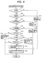
- Fig. 6 shows the discharge path selecting task (step S104), which, upon activation, discriminates whether there is designated a function specific to the large-sized finisher 27 such as book binding or Z-folding (steps S111, S112). If designated, the third discharge path capable of connecting the finisher 27 is selected (S118). Also the positioning of the third discharge path on a lateral face of the apparatus not dimensionally limited in the upward or downward direction allows to limit the height of the apparatus and to improve the convenience of use of the apparatus (original handing on the original table 2 and operability of the operation unit). Also the configuration of placing the dual-side path 25 under the latent image forming drum 18, the transfer roller 19 and the thermal fixation rollers 20 allows to meet the strict requirement in the height of the apparatus.
- the specified finisher function can be utilized without a cumbersome operation of changing the discharge path for the print of the printer, the FAX print or the copy each time, whereby the throughput of the apparatus can be improved. Also such configuration allows to provide a compact apparatus, since the function for passing the special paper or the high performance post-treatment function need not be provided in all the plural discharge paths.
- the discharge path capable of discharging the special paper can be utilized without a cumbersome operation of changing the discharge path for the print of the printer, the FAX print or the copy each time, whereby the throughput of the apparatus can be improved. Also such configuration allows to provide a compact apparatus, since the function for passing the special paper or the high performance post-treatment function need not be provided in all the plural discharge paths.
- a print instruction command generating task (S124) whereupon the present task is terminated. Also in case the print command is not from the PC terminal on the LAN, the present task is terminated.
- the print command having such a format allowing discrimination of the image input means utilized for image input by the judgment of the print command itself, but equivalent discrimination is naturally possible by directly judging whether the image input means utilized for image input is the FAX interface unit 103, the LAN interface unit 102 or the printer interface unit 104.
- the priority is at first given to the setting of book binding, folding or special paper in the steps S111 to S113.
- Next priority is given to the discharge setting determined by the print command or by the operation panel 112.
- the discharge path setting determined by the copy mode/FAX mode/printer mode has the lowest priority. Stated differently, there is normally utilized the discharge path determined according to the copy mode/FAX mode/printer mode, but, in case the function of a specified discharge path (third discharge path in the present embodiment) is required for example for the setting of book binding, folding or special paper, there is selected such discharge path.
- the discharge path for specified finisher function or for passing the special paper can be utilized without a cumbersome operation of changing the discharge path for the print of the printer, the FAX print or the copy each time, whereby the throughput of the apparatus can be improved. Also such configuration allows to provide a compact apparatus, since the function for passing the special paper or the high performance post-treatment function need not be provided in all the plural discharge paths.
- the discharge path selecting task has been explained as the control by the CPU 101, but a similar control may be executed in the printer driver of the PC terminal on the LAN. If suitable communication means and protocol are given, it is easy for those skilled in the art to execute the discharge path selecting control, similar to that explained in the foregoing, by the printer driver of the PC terminal while acquiring the status of the present apparatus serving as a printer.
- Fig. 7 shows a print instruction command generating task, which generates a print instruction command describing the content of a print process to be executed by the electrophotographic recording unit 107 in a specified format and issuing such command to the electrophotographic recording unit 107.
- step S131 there is at first set either dual-side printing or single-side printing in the print instruction command, based in the input print command (step S131). Then there are set the discharge path information selected in the discharge path selecting task (S132), and the number of prints (S133). Then there is set special paper information (S134) set in a special paper setting task to be explained later, and thus generated print instruction command is outputted, together with the print data, to the electrophotographic recording unit 107 (S135).
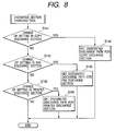
- Fig. 8 shows a discharge section changing task, which is activated when the setting of the discharge path is changed by the operation panel 112 or from the PC terminal on the LAN.
- step S141 At first there is discriminated whether the setting of the copy discharge section is changed (step S141), and, if changed, the designated discharge path is set as the discharge section for the copy (S144). Then there is discriminated whether the setting of the FAX discharge section is changed (S142), and, if changed, the designated discharge path is set as the discharge section for the facsimile (S145). Then there is discriminated whether the setting of the printer discharge path is changed (S143), and, if changed, the designated discharge path is set as the discharge port for the printer (S146).
- the discharge path designated in the above-described process is naturally any of the first to third discharge paths 22 to 24.
- the discharge paths to be employed in the recording processes of the copy/FAX/printer are respectively assigned to the first to third discharge paths 22 to 24.
- Fig. 8 shows a case of changing the discharge ports for the copy/FAX/printer, but such example is not restrictive and it is also possible to execute such setting as to change the discharge port for each client terminal or for each job.
- control as to execute the output of a printing designated from the client terminal or of a print job by a specified discharge port.
- Fig. 9 shows a special paper setting task, which is activated when the special paper is set by the operation panel 112 or by the PC terminal in the LAN.
- this task there is discriminated whether cardboard, thin paper, OHP sheet or free-size sheet is set (steps S151 to S154), and, if set, respectively corresponding special paper modes are set (S155 to S158) and such mode is set in the RAM 111 whereupon the present task is terminated.
- Fig. 10 shows a communication task to be used for exchanging commands between the CPU 101 and the MPU 201 and informing the CPU 101 of the state information, etc. of the electrophotographic recording unit 107.
- the MPU 201 discriminates whether there exists a print instruction command (generated by the print instruction command generating task shown in Fig. 7) from the CPU 101 (step S161).
- the print instruction command contains not only the print instruction but also information indicating the resolution required for printing, recording sheet size, and designated sheet cassette stage, also information indicating dual-size recording or single-side recording as shown in Fig. 7 and information on the discharge port for the recording sheet.
- Such information to be informed to the CPU 101 includes information on the sheet jamming in various units, information on the connected finisher and information on the state thereof.
- Fig. 11 is a sensor state monitoring task of the MPU 201.
- the sensor state monitoring task is activated at every 2 msec for example by timer interruption, and acquires the on/off state information of the sensors 301 to 311 (information whether each sensor detects the sheet) (step S171) and stores the acquired sensor information in the RAM 202 (S172).
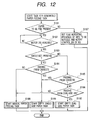
- Fig. 12 shows the mode of activation of the task for generating the paper feed task.
- the MPU 201 discriminates whether the paper feed section such as a designated sheet cassette contains a feedable sheet (step S181). For such sheet detection, there are used unrepresented sensors provided in the positions of the cassettes 11 to 13. In the absence of paper, there is set a flag indicating the information is present (S187), and the communication task shown in Fig. 10 informs the CPU 101 of a fact that the print instruction command cannot be executed and the reason therefor, whereupon the present task is terminated.
- S189 In case of sheet feeding from the cassette, there is activated an available single-side paper task (S189).
- the single-side paper task is present in plural units in order that the plural sheets of different feed timings can be simultaneously present in the apparatus. In this manner a next sheet can be fed before the discharge of the fed sheet is not yet completed, whereby the throughput of the apparatus can be improved.
- step S191 When the single-side paper task is activated, power supply is initiated to the heater of the thermal fixation unit, etc. to activate the main motor 208 and the DC motor 209 (step S191).
- the motor 209 is so controlled as to convey the recording sheet at a speed of 140 mm/sec, which enables latent image formation, image transfer and thermal fixation in a stable manner.
- the pickup roller 401 is rotated by the motor 205 and is pressed down by the driving force of the main motor 208, transmitted by an unrepresented clutch (S192).
- the motor 205 (stepping motor) is activated, whereby the roller 401 starts to rotate under acceleration so as to convey the recording sheet at a speed of 210 mm/sec (faster than the speed of 140 mm/sec enabling the aforementioned latent image forming drum 18 to execute the recording operation), thereby picking up the recording sheet (S194).
- the pickup roller 401 is lifted (S196).
- the clutch of the driving mechanism 206 is turned on to rotate the rollers 403, 404 by the driving force of the main motor 208 transmitted through the driving mechanism 206, so as to convey the sheet at a speed of 280 mm/sec (S198).
- the motor 205 is decelerated and is then stopped (S200). This operation is to prevent erroneous conveying of a next sheet by the rotation of the rollers 402. In this manner there can be prevented a situation wherein the trailing end of a preceding sheet stops in a state caught in the rollers 402 and a next sheet is erroneously conveyed, and such sheet is conveyed by the rollers 403. Since the motor 205 is composed of a stepping motor, there is executed such control as to decelerate and then stop the motor 205 in order to reduce the noises, but there may also be employed a configuration of simply turning off a clutch or the like.
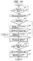
- step S201, S202 in Fig. 14 the clutch of the driving mechanism 206 is once turned off in the presence of a preceding sheet, thereby stopping the drive for the rollers 403, 404 (S203, S204).
- the presence of the preceding sheet is discriminated by an unrepresented task, and the preceding sheet is judged absent or present respectively if the leading end of such preceding sheet is detected after the lapse of a predetermined time, determined by the sheet size, from the passing of the trailing end of the preceding sheet through the sensor 302 or if such detection of the leading end takes place before the lapse of such predetermined time.
- Such discrimination is made in order to adjust the sheet gap to the preceding sheet and to adjust the sheet registration.
- the sheet gap is variable according to the sheet size and is 36.5 mm in case of A4/letter size.
- control can be achieved by stopping the drive of the rollers 403, 404 by the driving mechanism 206 (turning off the clutch for transmitting the power of the main motor 208) for a predetermined time determined by the size of the preceding sheet. After the lapse of the predetermined time (S205), the clutch of the driving mechanism 206 for transmitting the power of the main motor 208 is turned on to redrive the rollers 403, 404 (S206).
- the motor 207 is so accelerated as to convey the sheet with a speed of 280 mm/sec (S210).
- the stepping motor 207 enters a control of decelerating to a speed capable of conveying the sheet at a speed of 140 mm/sec (S212), because the process speed of image development, image transfer, image fixation, etc. is as low as 140 mm/sec.
- the clutch of the deriving mechanism 206 for transmitting the power of the main motor 208 is turned off to stop the rollers 403, 404 (S213).
- Such control is to avoid a situation where the sheet generates a large loop at the position of the rollers 405 by the speed difference between the motors 207 and 206, thus resulting in a Z-fold or a jamming in the sheet.
- the clutch of the driving mechanism 206 is turned off, but such objective can also be attained by decelerating the motor 206 so as to obtain a sheet conveying speed same as or lower than the rotation of the rollers 405.
- the timing of forming the latent image by the laser light recording and process-related control such as image development and image transfer (S215).
- the exposure by the laser unit 17, development of the latent image on the latent image forming drum 18, transfer by the transfer roller 19 and toner fixation by the thermal fixation rollers 20 are executed.
- the senor 304 is composed of a mechanical actuator, of which movement detects the presence or absence of the sheet. In such configuration, there is generated a time difference between the actual time of passing of the trailing end of the sheet and the detection of passing of the trailing end of the sheet. For this reason, the sensor 304 is not used for controlling the timing for terminating the laser light emission.
- step S219 identifies the presence of a succeeding sheet
- the sequence proceeds to a next step (S221 in Fig. 16) without terminating the power supply to the high voltage section of the process unit.
- the motor 210 is driven so as to convey the sheet with a speed of 140 mm/sec (S223).
- the discharge path of the rollers 411 (first discharge port 22), the discharge path of the rollers 412 (second discharge port 23), the discharge path of the rollers 413 (third discharge port 24) or the dual-side path 25 is selected as the set discharge port (S226, S227, S228), and the discharge port is selected according to such discrimination.
- the first discharge task is activated in case of discharge to the first discharge port (S229)
- the second discharge task is activated in case of discharge to the second discharge port (S230)
- the third discharge task is activated in case of discharge to the third discharge port (S231)
- the dual-side path task is activated in case of guiding the sheet to the dual-side path (S232).
- Fig. 17 shows the above-mentioned first discharge task.
- the flappers 501, 502 are switched in a direction toward the first discharge port 22 (S241).
- the flappers are switched, in case the discharge path is changed between a preceding sheet and the present sheet, in such a manner that the respective flapper is switched at a timing when the trailing end of the preceding sheet passes through such flapper, to be determined by the number of steps after the passing of the trailing end of the preceding sheet through the sensor 305.
- the acceleration control of the motor 210 is started at a timing when the trailing end of the sheet is disengaged from the rollers 409.
- the stepping motor 210 executes acceleration control from the process speed of 140 mm/sec to a speed of 350 mm/sec (S244). Such acceleration is made in order to reduce the first copy time (staying time of the sheet in the apparatus).
- the motor 210 does not execute acceleration but continues the conveying operation at 140 mm/sec.
- the acceleration to 350 mm/sec is not executed in order to improve the stacking property of the sheets after discharge.
- the sheets are discharged in succession at a speed of 350 mm/sec, the discharged sheets are stacked on the tray in a distorted manner because of the high discharging speed.
- the presence of the succeeding sheet is discriminated, as explained in the foregoing, in an unrepresented task whether the succeeding sheet is in the course of feeding or whether a next print instruction is given from the CPU 101 when the trailing end of the sheet passes the sensor 304, and the succeeding sheet is judged absent or present respectively if both conditions are negated or if either of the conditions is affirmative.
- the rollers 411 of the discharge path are driven by the motor 210, same as that for the rollers 410, and discharge the conveyed sheet to the exterior of the apparatus.
- the sensor 306 detects the leading end of the sheet (S245) and then the trailing end thereof (S246), whereupon, in the absence of the succeeding sheet (S247), the motor 210 is decelerated and stopped (S248).
- the CPU 101 In case special paper such as cardboard, thin paper, OHP sheet or free-size sheet is selected as the sheet, the CPU 101 generates such print instruction command as to execute the discharge from the first discharge port 22, namely the discharge path of the rollers 411, regardless of the setting of the discharge port.
- the discharge path of the rollers 411 (first discharge port) has a smaller curvature in the discharge path than in the discharge path of the rollers 412 (second discharge port) or that of the rollers 413 (third discharge port) and is the shortest sheet discharge path, thereby decreasing the stress given to the sheet.
- Such configuration allows to limit the height of the apparatus and to improve the convenience of use of the apparatus (original handing on the original table 2 and operability of the operation unit).
- the configuration of placing the dual-side path 25 under the latent image forming drum 18, the transfer roller 19 and the thermal fixation rollers 20 allows to meet the strict requirement in the height of the apparatus.
- the special paper is discharged from the first discharge path because of the smallest curvature thereof, but a same effect can naturally be obtained by selecting any discharge path having a small curvature.
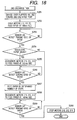
- Fig. 18 shows the second discharge task.
- the flappers 501, 502 are switched in a direction toward the second discharge port (step S251).
- the flappers are switched in such a manner that the respective flapper is switched at a timing when the trailing end of the preceding sheet passes through such flapper, to be determined by the number of steps after the passing of the trailing end of the preceding sheet through the sensor 305.
- the motors 212, 213 are driven at a speed of 140 mm/sec (S252), and, when the sensor 305 detects the passing of the trailing end of the sheet (S253), in the absence of the succeeding sheet as explained in the foregoing (S254), the acceleration control of the motors 210, 212, 213 is started at a timing when the trailing end of the sheet is disengaged from the rollers 409 (S255).
- These three motors are accelerated simultaneously in order to prevent bending or breakage of a large-sized sheet such as of A3 or B4 size as the rollers driven by such motors engage with such large-sized sheet.
- a step S255 the motors 210, 212, 213 are accelerated from the process speed of 140 mm/sec to a speed of 350 mm/sec. Such acceleration is made in order to reduce the first copy time (staying time of the sheet in the apparatus). On the other hand, in the absence of the succeeding sheet, the stepping motor 210 is not accelerated but continues the conveying operation at 140 mm/sec.
- the sheet is conveyed by a number of steps determined by the sheet size (S257) and the motors 210, 212, 213 are decelerated to 140 mm/sec (S258) thereby discharging the sheet from the second discharge port 23.
- the sheet is decelerated in the vicinity of the discharge port in case of sheet discharge from the second discharge port positioned above the first discharge port 22, because the stacking property of the sheets after discharge tends to be deteriorated in comparison with the sheet discharge from the first discharge port since the conveying path has a larger curvature (stronger curving) in the vicinity of the discharge port.
- the motors 210, 212, 213 are stopped (S260).
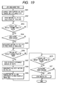
- Fig. 19 shows the third discharge task.
- the flappers 501, 502 are switched in a direction toward the second discharge port (S261).
- the timing of flapper switching is same as explained before.
- the motors 212, 213 are driven at a speed of 140 mm/sec (S262), and, when the sensor 305 detects the passing of the trailing end of the sheet (S263), in the absence of the succeeding sheet as explained in the foregoing (S264), the acceleration control of the motors 210, 212, 213 is started at a timing when the trailing end of the sheet is disengaged from the rollers 409 (S265).
- These three motors are accelerated simultaneously in order to prevent bending or breakage of a large-sized sheet such as of A3 or B4 size as the rollers driven by such motors engage with such large-sized sheet.
- a step S265 the motors 210, 212, 213 are accelerated from the process speed of 140 mm/sec to a speed of 350 mm/sec. Such acceleration is made in order to reduce the first copy time (staying time of the sheet in the apparatus). On the other hand, in the absence of the succeeding sheet, the speed of the stepping motor 210 is not changed.
- the sheet is conveyed by a number of steps determined by the sheet size to a position where the trailing end of the sheet is caught by the rollers 412 (S267) and then the motors 210, 212, 213 are decelerated and stopped (S268).
- the flapper 503 is so switched that the sheet does not move backward to the upstream side of the conveying path, and the motor 213 is driven in the reverse direction (S269).
- the motor 213 is accelerated to 350 mm/sec. Such acceleration is made in order to reduce the first copy time (staying time of the sheet in the apparatus).
- the sensor 308 detects the passing of the trailing end of the sheet (S270), and, in the absence of the succeeding sheet (S271), the motor 213 is stopped (S272).
- the large-sized finisher 27 capable of Z-folding, book binding, etc. can be mounted on the third discharge port. Therefore, in case the function such as Z-folding or book binding is designated, the CPU 101 designates the third discharge path by the print instruction command regardless of the setting of the discharge port. Also such configuration allows to limit the height of the apparatus and to improve the convenience of use of the apparatus (original handing on the original table 2 and operability of the operation unit). Also the configuration of placing the dual-side path 25 under the latent image forming drum 18, the transfer roller 19 and the thermal fixation rollers 20 allows to meet the strict requirement in the height of the apparatus. Also in case the large-sized finisher 27 capable of Z-folding, book binding, etc.
- the CPU 101 executes sheet discharge through another discharge port regardless of the setting of the discharge path, as long as the first and second discharge ports are free from abnormality and the function of the large-sized finisher such as Z-folding or book binding is not utilized. This is also adopted in case a jam is generated in the second discharge port.
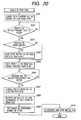
- Fig. 20 shows a dual-side path task for inverting the sheet after recording on a side, for conveying into the dual-side unit.
- the flappers 501, 502 are switched to the first discharge port (step S281), at a timing explained in the foregoing.
- the motor 210 conveys the sheet at the process speed in the presence of the succeeding sheet (S283) or with acceleration to 350 mm/sec in the absence of the succeeding sheet (S284). It is then stopped after conveying the sheet, after passing the sensor 305, by a number of steps determined by the sheet size and corresponding to a position where the trailing end of the sheet passes through the flapper 501 (S285).
- the sensors 309, 310 are used to discriminate whether a preceding sheet is present in the dual-side path (S286), and the flapper 501 is switched to the dual-side path under the condition that the preceding sheet is absent (S287). Also the stepping motors 210, 211 are reversed and accelerate the rollers 410, 415, 416, 417 to 350 mm/sec (S288). Also in case of discrimination that the preceding sheet is present, the reversing of the motor 210 is started after waiting until the sensors 309, 310 discriminate that the preceding sheet is absent.
- the sheet is conveyed by a predetermined number of steps (S289), and the motor 211 is decelerated and stopped when the sheet is conveyed to the vicinity of the upstream side, in the conveying direction, of the jointing point of the conveying path 14 and the dual-side path 25 (S290) whereupon the present task is terminated.
- the sheet is not stopped at the position of the sensor 310 but is conveyed to the vicinity of the jointing point at the downstream side in the sheet conveying direction, in order not to cause collision with the sheet fed from the sheet cassette and to reduce the gap to the preceding sheet as far as possible.
- the sheet discharging speed from the first or third discharge port is 350 mm/sec while the sheet conveying speed to a position in front of the latent image forming drum 18 (position of the rollers 405) is 280 mm/sec, in order to avoid damage to the sheet by rapid deceleration in case of deceleration of the sheet conveying speed in such position and to minimize the staying time of the sheet in the apparatus.
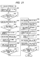
- Fig. 21 shows the dual-side paper task, which is to convey again (re-feed) the sheet, conveyed into the dual-side unit by the dual-side path task shown in Fig. 20, into the rollers 404, 405,.. from the dual-side unit.
- step S291 if a print instruction command for recording on the rear side of the sheet from the CPU 101, the motor 211 conveys the sheet with acceleration to 210 mm/sec (step S291).
- the sensor 302 detects the leading end of the sheet (S292), and, after the lapse of a predetermined time (required by the leading end of the sheet to reach a position of about 10 mm at the downstream side of the sensor 404) (S293), there is discriminated whether a preceding sheet is present (S294).
- the discrimination of the presence/absence of the preceding sheet is executed in the same manner as in the single-side paper task.
- the clutch for transmitting the power from the main motor 208 is once turned off and the drive of the motor 211 is stopped (S295).
- the clutch for transmitting the power from the main motor 208 is turned on and the motor 211 is re-activated (S297).
- the stopping control of the steps S295 to S297 is not executed.
- the motor (stepping motor) 207 is driven under acceleration to convey the sheet at a speed of 280mm/sec (S301).
- the motor 207 is decelerated to a speed capable of conveying the sheet at a speed of 140 mm/sec (S303).
- the clutch of the driving mechanism 206 is turned off and the motor 211 is decelerated and stopped (S304). Then, after the motor 211 is stopped for about 50 msec (S305), the motor 211 is re-activated in a state where the clutch of the driving mechanism 206 remains turned off so that the rollers 403, 404 can freely rotate (S306). The re-activation of the motor 211 is continued until the trailing end of the sheet passes through the position of the sensor 310.
- the motor 211 is stopped for about 50 msec because a loop will be formed in the sheet if the rollers 417 are decelerated while they still engage with the trailing end portion of a long sheet such as of A3 size. Also, the motor 211 is activated again immediately thereafter in order to push the sheet by the rollers 417, since the rollers 405 alone cannot provide a sufficient conveying force for a long sheet.
- step S307 there is executed a process same as the process D in the single-side paper task (step S207 and the ensuing steps in Fig. 14).
- the process is so illustrated, for the purpose of simplicity, as if it jumps to the position D in the single-side paper task, but, in practice, the process does not jump but is executed in the same manner in another task.
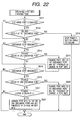
- Fig. 22 shows the discharge port information changing task, which is to change the discharge port according to an abnormality in the discharge port designated by the print instruction command and periodically monitors the abnormality in the discharge port.
- the MPU 201 discriminates whether the first discharge port 22 is designated as the discharge port (step S311). If designated, there is discriminated, based on the information from the sensor 306 and the finisher 26, whether the first discharge port 22 is in an abnormal state for example by paper jamming (S312). If the first discharge port 22 is in an abnormal state, the function of the printer unit is terminated as a printer abnormality for example by paper jamming (S318). The function of the printer unit is terminated because the abnormality in the first discharge port, being in the most upstream position, may possibly clog the conveying paths to other discharge ports.
- the second discharge port 23 is designated (S313). If designated, there is discriminated, based on the information from the sensor 307 and the finisher 26, whether the second discharge port 23 is in an abnormal state for example by paper jamming (S314). If the second discharge port 23 is in an abnormal state, and if the discharge to the first discharge port is possible for the job for which the second discharge port is set, the discharge port information is changed to the first discharge port and the presence of a change is informed (S319). In this manner there can be utilized a discharge path without abnormality, without a cumbersome operation of changing the discharge path for the print of the printer, the FAX print or the copy each time, whereby the throughput of the apparatus can be improved.
- the sensor 308 is used for discriminating whether an abnormality such as paper jamming is present in the third discharge port 24 (S315, S316). This process is same also in case the second discharge port 23 is not designated or in case the second discharge port 23 is not abnormal.
- the third discharge port 24 has an abnormality such as paper jamming
- the discharge to the second discharge port 23 also becomes abnormal since the second discharge port 23 constitutes the conveying path to the third discharge port 24.
- the job for which the third discharge port 24 is designated cannot use the second discharge port, so that, if the discharge to the first discharge port is possible, the discharge port information is changed to the first discharge port and the presence of a change is informed (S320). In this manner there can be utilized a discharge path without abnormality, without a cumbersome operation of changing the discharge path for the print of the printer, the FAX print or the copy each time, whereby the throughput of the apparatus can be improved.
- the third discharge port 24 is not in an abnormal state, there is discriminated whether an abnormality such as paper jamming is present in the finisher 27 (S317).
- an abnormality in the finisher 27 for the job for which the third discharge port 24 is set, the setting is changed to the available first discharge port 22 or second discharge port 23 and such change is informed (S321), whereupon the present task is terminated.
- the paper jamming is assumed to be an abnormality in the discharge port, but there may also be detected other phenomena such as a failure in the finisher or absence of staple in the stapler as the abnormality.
- the aforementioned control is assumed to be executed by the MPU 201, but such example is not restrictive and a similar control can be executed by the CPU 101 or by the printer driver of the PC terminal on the LAN.
- the information indicating the presence of a change in the discharge port information, set in the aforementioned control is utilized in the single-side paper task explained in the foregoing.
- rollers other than those 403, 404 are assumed to be driven by independent stepping motors or DC motors, but such other rollers may also be driven, like the rollers 403 and 404, by the motor 208, utilizing a speed varying mechanism and a clutch as in the driving mechanism 206.
- rollers 403, 404 it is also possible to drive the rollers 403, 404 with the independent motors.
- clutches or the like are provided between the motors and the rollers 403, 404 to release the same from the driving force thereby enabling free rotation of the rollers 403, 404 at the sheet deceleration as in the aforementioned step S304 or at the sheet pushing operation by the rollers 417 of the dual-side unit.
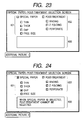
- Figs. 23 to 25 show an example of the user interface for designating special paper or a post-treatment such as book binding or folding (special paper selecting control corresponds to the aforementioned process in Fig. 9).
- the process shown in Figs. 23 to 25 may be constructed as a program for the CPU 101 and stored in the ROM 110.
- the special paper is discharged to the first discharge path 22, while the third discharge path 24 is selected in case a function of the finisher 27 is selected. Therefore the special paper and the post-treatment setting are not compatible.
- Figs. 23 to 25 show an image (or screen) on the operation panel 112 for selecting the special paper and the mode of post-treatment, and such interface allows the user to set the special paper and the post-treatment within a same image.
- this image there are provided buttons 601 for selecting the mode of special paper, those 602 for selecting the mode of post-treatment, and an echo area 603 for displaying an error (or alarm) message.
- the user can execute setting of the special paper and that of the post-treatment by operating the aforementioned buttons 601, 602 by an unrepresented pointing device (mouse or the like) or by a touch panel provided on the display of the operation panel 112.
- the present user interface executes control in such a manner that the designation of special paper and the designation of post-treatment can be selected only in exclusive manner.
- the CPU 101 has to execute the discharge by the first discharge path 22, so that the image is so controlled as to disable the setting on the finisher 27. More specifically, after a button 601 for selecting a mode of special paper is selected as shown in Fig. 24, the buttons 602 for selecting the modes of post-treatment are displayed with a lowered display luminance (or a lowered density) to indicate that the selection is disabled (also input on the buttons 602 being disregarded). Also the echo area 603 is used to display an alarm message "Post-treatment cannot be selected when special paper is selected".
- the CPU 101 has to execute the discharge by the third discharge path 24, so that the image is so controlled as to disable the setting on the special paper. More specifically, after a button 602 for selecting a mode of post-treatment is selected as shown in Fig. 25, the buttons 601 for selecting the modes of special paper are displayed with a lowered display luminance (or a lowered density) to indicate that the selection is disabled (also input on the buttons 601 being disregarded). Also the echo area 603 is used to display an alarm message "Special paper cannot be selected when post-treatment is selected".
- a driver software of the client PC on the LAN contains in advance the processes shown in Figs. 23 to 25 and may be stored in a hard disk shown in Fig. 28.
- driver software enables the user of PC to execute such control as to select the designation of special paper and the designation of post-treatment only in exclusive manner, without going to the location of the apparatus, thus providing an advantage for the PC user.
- the image is so constructed as to execute the selections of special paper and post-treatment within a same image, but there is only required such control that the settings of special paper and post-treatment are not compatible in the setting image and it is not necessary to execute the setting of special paper and that of post-treatment within a same image as shown in Figs. 23 to 25.
- Fig. 26 shows another embodiment of the present invention, wherein the lower discharge path has a larger curvature (stronger curve) while the upper discharge path has a smaller curvature (milder curve).
- Such configuration also limits the height of the apparatus and improves the convenience of use thereof (original handing on the original table 2 and operability of the operation unit) as in the embodiment shown in Fig. 1.
- the upper discharge path 22 with smaller curvature is used as the first discharge path 22 shown in Fig. 1 and the lower discharge path 23 is used as the second discharge path 23 shown in Fig. 1.
- Fig. 27 is a perspective view of the image forming apparatus of the another embodiment shown in Fig. 26.
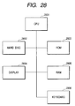
- Fig. 28 shows the configuration of a PC connected to the LAN interface unit 102, wherein provided are a CPU 2801 for controlling the entire PC, a hard disk 2802 storing programs, including a driver software for remote control of the image forming apparatus in the control as shown in Figs. 23 to 25, a ROM 2803 storing programs to be executed by the CPU 2801, a display 2804 for displaying images as shown in Figs. 23 to 25, a RAM 2805 to be used as a work area in the program execution, and an operation unit 2806 including a mouse, a keyboard, etc.
- the driver software as shown in Figs. 23 to 25 there are executed selection of discharge paths, setting of special paper and post-treatment.
- the aforementioned embodiments provide following excellent effects in the control of the sheet conveying speed.
- a configuration of conveying sheet, in the conveying paths before and after the latent image forming drum (image forming means) 18, at a higher conveying speed than the conveying speed (140 mm/sec) in the vicinity of the latent image forming drum 18 provides an excellent effect of reducing the staying time of the sheet in the apparatus, thereby significantly improving the throughput of the image forming process.
- the sheet conveying from the sheet cassettes to the latent image forming drum 18 can be made faster by a configuration of conveying the sheet from the sheet cassettes 11 to 13 by the rollers 402 at a speed of 210 mm/sec faster than the sheet conveying speed of 140 mm/sec in the vicinity of the latent image forming drum 18, then accelerating the sheet to 280 mm/sec by the rollers 403, 404 and decelerating the sheet by the rollers 405 immediately in front of the latent image forming drum 18 to the sheet conveying speed (140 mm/sec) in the vicinity of the latent image forming drum 18.
- the sheet conveying in the conveying path after the latent image forming drum (image forming means) 18 can be made faster by a configuration of accelerating the sheet to 350 mm/sec at maximum for the sheet discharge, after passing the latent image forming drum 18, thermal fixation roller 20 and rollers 409.
- the sheet conveying in the conveying path after the latent image forming drum (image forming means) 18 can be made faster by accelerating the sheet to 350 mm/sec at maximum for re-feeding in the dual-side unit.
- the sheet is discharged from the discharge path by accelerating to 350 mm/sec only in the absence of the succeeding sheet but such acceleration is not executed in the presence of the succeeding sheet, so that there can be achieved high-speed and appropriate discharge control satisfying both the high-speed sheet conveying and the sheet alignment on the discharge tray.
- the rollers 403, 404 are released from the driving power of the driving mechanism 206 whereby appropriate sheet re-feeding can be achieved without generating a loop even in a long sheet which may simultaneously engage with the rollers 417, 405, thus without causing jamming, deformation or breakage of the sheet or deterioration of the recorded image quality and also without deficiency in the conveying power.
- the first discharge path 22 is given a smaller curvature to enable discharge of special paper while other discharge paths are given a larger curvature. In this manner there is obtained an excellent effect of meeting the requirement for the height of the apparatus and also passing special paper without damaging.
- a configuration of selecting a specified one of the plural discharge paths according to the function state of the apparatus such as designation of specified post-treatment, designation of special paper or an error state, regardless of the default conditions for controlling the discharge paths, provides an excellent effect that the plural discharge paths can be appropriately selected and that the plural discharge paths can be automatically selected without requiring any cumbersome selecting operation. Furthermore, there can be obtained an excellent effect that the discharge path for special paper or that for finisher can also be used for the classified discharge for the prints of printer mode/FAX mode/printer mode, whereby the apparatus can be made compact.
- the configuration of selecting a specified on of the discharge paths according to the designation of special paper or post-treatment, regardless of the default conditions for controlling the discharge paths, is very effective in the configuration utilizing in-body sheet discharge and also utilizing an external large-sized finisher as in the foregoing embodiments.
- the discharge to the third discharge path 24 is necessary in case of designation of a specified post-treatment to be executed in the external finisher 27 which is not limited in space in the upper or lower part thereof.
- the external finisher 27 which is not limited in space in the upper or lower part thereof.
- a control capable, in case of an error in sheet conveying such as sheet jamming, of selecting a discharge path for discharge different from the discharge path in which the error is detected, provides an excellent effect of automatically and appropriately selecting the plural discharge paths without requiring any cumbersome selecting operation.
- a configuration of prohibiting either of the designation of the post-treatment and the designation of the special paper in case the other is designated by the user provides an excellent effect of preventing erroneous function of the apparatus by a useless designating operation and allowing the user to recognize the function of the apparatus and the method of use thereof while the apparatus in actual use.
- the first discharge path has such a curvature capable of discharging special paper, there can be obtained an excellent effect that any paper can be passed therein in a standard configuration without the post-treatment apparatus.
- the first discharge path has such a curvature capable of discharging special paper and smaller than the curvature of the second discharge path, there can be obtained an excellent effect that any paper can be passed therein in a standard configuration without the post-treatment apparatus and that the height of the apparatus can be limited even in the presence of the second discharge path.
- an image forming apparatus provided with plural discharge paths and adapted, after image formation by image forming means of a predetermined system, to discharge an image bearing sheet from any of such discharge paths to the exterior of the apparatus
- a control method for the image forming apparatus and a control program for the image forming apparatus there is adopted such control as to set one of the plural discharge paths for each of the print of printer mode/FAX mode/copy mode and to select specified one of the plural discharge paths for discharge, regardless of the aforementioned setting, according to the function state of the apparatus (selection of special paper, selection of post-treatment function or abnormality in the discharge path), so that there can be obtained an excellent effect of appropriately setting the selection of the plural discharge paths of the image forming apparatus and automatically and appropriately selecting the plural discharge paths according to other conditions such as designation of a specified post-treatment, designation of special paper or error generation, without requiring a cumbersome selecting operation.
- the first discharge path has such a curvature capable of discharging special paper, there can be obtained an excellent effect that any paper can be passed therein in a standard configuration without the post-treatment apparatus.
- the first discharge path has such a curvature capable of discharging special paper and smaller than the curvature of the second discharge path, there can be obtained an excellent effect that any paper can be passed therein in a standard configuration without the post-treatment apparatus and that the height of the apparatus can be limited even in the presence of the second discharge path.
- control is executed in such a manner that the setting of special paper and the setting of post-treatment are selected exclusively in order to avoid erroneous function of the apparatus.
Landscapes
- Physics & Mathematics (AREA)
- General Physics & Mathematics (AREA)
- Engineering & Computer Science (AREA)
- Ceramic Engineering (AREA)
- Textile Engineering (AREA)
- Control Or Security For Electrophotography (AREA)
- Separation, Sorting, Adjustment, Or Bending Of Sheets To Be Conveyed (AREA)
- Accessory Devices And Overall Control Thereof (AREA)
- Facsimiles In General (AREA)
- Paper Feeding For Electrophotography (AREA)
Abstract
Description
Claims (23)
- An image forming apparatus provided with:wherein said special paper setting means and said post-treatment setting means are selected in exclusive manner.first reception means for receiving print data from an external terminal;reading means for reading an image and outputting read print data; andrecording means for recording an image on a recording medium based on the received data, the apparatus characterized by comprising:discrimination means for discriminating whether said print data are received either from said first reception means or said reading means;first discharge means and second discharge means for discharging the recording medium recorded by said recording means;discharge setting means for setting whether to discharge the recording medium to said first discharge means or to said second discharge means respectively corresponding to said first reception means and said reading means,wherein said first discharge means is positioned between said reading means and said recording means and said second discharge means is connectable to a post-treatment apparatus and is so positioned as to execute discharge to the exterior of said image forming apparatus;selection means for selecting either said first discharge means or said second discharge means;special paper setting means for setting special paper as the type of the recording medium to be recorded by said recording means;post-treatment setting means for setting post-treatment after recording by said recording means; andpost-treatment means adapted to execute said post-treatment and connected to said second discharge means,
- An image forming apparatus according to claim 1, comprisingwherein said selection means selects said first discharge means regardless of the setting by said discharge setting means in case special paper is set by said special paper setting means.discrimination means for discriminating whether the reception is made either from said first reception means or said reading means,recording means for recording an image on a recording medium based on received data,first discharge means and second discharge means for discharging the recording medium recorded by said recording means,discharge setting means for setting whether to discharge the recording medium to said first discharge means or to said second discharge means respectively corresponding to said first reception means and said reading means,selection means for selecting either said first discharge means or said second discharge means, andspecial paper setting means for setting special paper as the type of the recording medium to be recorded by said recording means,
- An image forming apparatus according to claim 1, comprising:wherein said selection means selects said second discharge means regardless of the setting by said discharge setting means in case post-treatment is set by said post-treatment setting means.discrimination means for discriminating whether the reception is made either from said first reception means or said reading means;recording means for recording an image on a recording medium based on received data;first discharge means and second discharge means for discharging the recording medium recorded by said recording means;discharge setting means for setting whether to discharge the recording medium to said first discharge means or to said second discharge means respectively corresponding to said first reception means and said reading means;selection means for selecting either said first discharge means or said second discharge means;post-treatment setting means for setting post-treatment after recording by said recording means; andpost-treatment means adapted to execute said post-treatment and connected to said second discharge means,
- An image forming apparatus according to claim 1, comprisingwherein said selection means selects said first discharge means regardless of the setting by said discharge setting means in case said second detection means detects abnormality in said second discharge means and the discharge to said first discharge means is possible.discrimination means for discriminating whether the reception is made either from said first reception means or said reading means,recording means for recording an image on a recording medium based on received data,first discharge means and second discharge means for discharging the recording medium recorded by said recording means,discharge setting means for setting whether to discharge the recording medium to said first discharge means or to said second discharge means respectively corresponding to said first reception means and said reading means,selection means for selecting either said first discharge means or said second discharge means, andfirst detection means and second detection means for respectively detecting whether said first discharge means and said second discharge means are abnormal,
- An image forming apparatus according to any of claims 1 to 4, further comprisingsecond reception means for receiving print data from a public line, wherein said discrimination means discriminates whether the reception is made from said first reception means, said reading means or said second reception means, andthird discharge means for discharging the recording medium recorded by said recording means,wherein said discharge setting means sets whether to discharge the recording medium to said first discharge means, said second discharge means or said third discharge means respectively corresponding to said first reception means, said reading means and said second reception means; andsaid selection means selects any of said first discharge means, said second discharge means and said third discharge means.
- An image forming apparatus according to claim 5, wherein said first discharge means and said third discharge means are positioned between said reading means and said recording means, and said second discharge means is so positioned as to be connectable to a post-treatment apparatus and to execute discharge to the exterior of said image forming apparatus.
- An image forming apparatus according to claim 1, wherein said first discharge means has a curvature capable of discharging special paper.
- An image forming apparatus according to claim 5, wherein said first discharge means has a curvature capable of discharging special paper and smaller than the curvature of said third discharge means.
- An image forming apparatus according to claim 5, further comprising third detection means for detecting whether said third discharge means is abnormal wherein said selection means selects said first discharge means regardless of the setting by said discharge setting means in case said third detection means detects an abnormality in said third discharge means and the discharge to said first discharge means is possible.
- An image forming apparatus according to claim 4, wherein said first discharge means is positioned at the upstream side of said second discharge means.
- An image forming apparatus according to claim 5, wherein said first discharge means and said third discharge means are positioned between said reading means and said recording means, said second discharge means is so positioned as to be connectable to a post-treatment apparatus and to execute discharge to the exterior of said image forming apparatus, and said first discharge means is positioned at the upstream side of said second and third discharge means.
- A control program for controlling, from a remote external information processing terminal, an image forming apparatus provided with first reception means for receiving print data from an external terminal, reading means for reading an image and outputting read print data, and recording means for recording an image on a recording medium based on the received or read data, the apparatus further including discrimination means for discriminating whether the reception is made either from said first reception means or said reading means, first discharge means and second discharge means for discharging the recording medium recorded by said recording means, and sheet discharge setting means for setting whether to discharge the recording medium to said first discharge means or to said second discharge means respectively corresponding to said first reception means and said reading means, wherein said first discharge means is positioned between said reading means and said recording means, and said second discharge means is connectable to a post-treatment apparatus and is so positioned as to discharge the recording medium to the exterior of said image forming apparatus,wherein said special paper setting step and said post-treatment setting step are exclusively selected.the program comprising:a special paper setting step of setting special paper as the type of the recording medium; anda post-treatment setting step of setting post-treatment after recording by said recording means,
- A method for controlling an image forming apparatus, comprising steps of:providing first reception means for receiving print data from an external terminal;providing reading means for reading an image and outputting read print data; andproviding recording means for recording an image on a recording medium based on the received data, the apparatus further including:providing discrimination means for discriminating whether said print data are received either from said first reception means or said reading means;providing first discharge means and second discharge means for discharging the recording medium recorded by said recording means;providing discharge setting means for setting whether to discharge the recording medium to said first discharge means or to said second discharge means respectively corresponding to said first reception means and said reading means,wherein said first discharge means is positioned between said reading means and said recording means and said second discharge means is connectable to a post-treatment apparatus and is so positioned as to execute discharge to the exterior of said image forming apparatus;providing selection means for selecting either said first discharge means or said second discharge means;providing special paper setting means for setting special paper as the type of the recording medium to be recorded by said recording means;providing post-treatment setting means for setting post-treatment after recording by said recording means;providing post-treatment means adapted to execute said post-treatment and connected to said second discharge means; andselecting said special paper setting means and said post-treatment setting means in exclusive manner.
- A method for controlling an image forming apparatus according to claim 13, including steps ofproviding discrimination means for discriminating whether the reception is made either from said first reception means or said reading means,providing recording means for recording an image on a recording medium based on received data,providing first discharge means and second discharge means for discharging the recording medium recorded by said recording means,providing discharge setting means for setting whether to discharge the recording medium to said first discharge means or to said second discharge means respectively corresponding to said first reception means and said reading means,providing selection means for selecting either said first discharge means or said second discharge means,providing special paper setting means for setting special paper as the type of the recording medium to be recorded by said recording means, andselecting, by said selection means, said first discharge means regardless of the setting by said discharge setting means in case special paper is set by said special paper setting means.
- A method for controlling an image forming apparatus according to claim 13, including steps ofproviding discrimination means for discriminating whether the reception is made either from said first reception means or said reading means,providing recording means for recording an image on a recording medium based on received data,providing first discharge means and second discharge means for discharging the recording medium recorded by said recording means,providing discharge setting means for setting whether to discharge the recording medium to said first discharge means or to said second discharge means respectively corresponding to said first reception means and said reading means,providing selection means for selecting either said first discharge means or said second discharge means,providing post-treatment setting means for setting post-treatment after recording by said recording means,providing post-treatment means adapted to execute said post-treatment and connected to said second discharge means, andselecting, by said selection means, said second discharge means regardless of the setting by said discharge setting means in case post-treatment is set by said post-treatment setting means.
- A method for controlling an image forming apparatus according to claim 13, including steps ofproviding discrimination means for discriminating whether the reception is made either from said first reception means or said reading means,providing recording means for recording an image on a recording medium based on received data,providing first discharge means and second discharge means for discharging the recording medium recorded by said recording means,providing discharge setting means for setting whether to discharge the recording medium to said first discharge means or to said second discharge means respectively corresponding to said first reception means and said reading means,providing selection means for selecting either said first discharge means or said second discharge means,providing first detection means and second detection means for respectively detecting whether said first discharge means and said second discharge means are abnormal, andselecting, by said selection means, said first discharge means regardless of the setting by said discharge setting means in case said second detection means detects abnormality in said second discharge means and the discharge to said first discharge means is possible.
- A method for controlling an image forming apparatus according to any of claims 13 to 16, said method further including steps ofproviding second reception means for receiving print data from a public line, wherein said discrimination means discriminates whether the reception is made from said first reception means, said reading means or said second reception means,providing third discharge means for discharging the recording medium recorded by said recording means,setting, by said discharge setting means, whether to discharge the recording medium to said first discharge means, said second discharge means or said third discharge means respectively corresponding to said first reception means, said reading means and said second reception means, andselecting, by said selection means, any of said first discharge means, said second discharge means and said third discharge means.
- An image forming method for use in an image forming apparatus according to claim 17, wherein said first discharge means and said third discharge means are positioned between said reading means and said recording means, and said second discharge means is so positioned as to be connectable to a post-treatment apparatus and to execute discharge to the exterior of said image forming apparatus.
- A method for controlling an image forming apparatus according to claim 13, wherein said first discharge means has a curvature capable of discharging special paper.
- A method for controlling an image forming apparatus according to claim 17, wherein said first discharge means has a curvature capable of discharging special paper and smaller than the curvature of said third discharge means.
- A method for controlling an image forming apparatus according to claim 17, further including steps ofproviding third detection means for detecting whether said third discharge means is abnormal, andselecting, by said selection means, said first discharge means regardless of the setting by said discharge setting means in case said third detection means detects an abnormality in said third discharge means and the discharge to said first discharge means is possible.
- A method for controlling an image forming apparatus according to claim 16, wherein said first discharge means is positioned at the upstream side of said second discharge means.
- A method for controlling an image forming apparatus according to claim 17, wherein said first discharge means and said third discharge means are positioned between said reading means and said recording means said second discharge means is so positioned as to be connectable to a post-treatment apparatus and to execute discharge to the exterior of said image forming apparatus, and said first discharge means is positioned at the upstream side of said second and third discharge means.
Applications Claiming Priority (6)
| Application Number | Priority Date | Filing Date | Title |
|---|---|---|---|
| JP2001074022 | 2001-03-15 | ||
| JP2001074022 | 2001-03-15 | ||
| JP2001115392 | 2001-04-13 | ||
| JP2001115392 | 2001-04-13 | ||
| JP2002045549 | 2002-02-22 | ||
| JP2002045549A JP3768900B2 (en) | 2001-03-15 | 2002-02-22 | Image forming apparatus, image forming apparatus control method, and image forming apparatus control program |
Publications (3)
| Publication Number | Publication Date |
|---|---|
| EP1241532A2 true EP1241532A2 (en) | 2002-09-18 |
| EP1241532A3 EP1241532A3 (en) | 2006-04-12 |
| EP1241532B1 EP1241532B1 (en) | 2010-02-17 |
Family
ID=27346253
Family Applications (1)
| Application Number | Title | Priority Date | Filing Date |
|---|---|---|---|
| EP02005926A Expired - Lifetime EP1241532B1 (en) | 2001-03-15 | 2002-03-14 | Image forming apparatus, control method thereof and control program therefor |
Country Status (5)
| Country | Link |
|---|---|
| US (1) | US6671472B2 (en) |
| EP (1) | EP1241532B1 (en) |
| CN (1) | CN100354761C (en) |
| AT (1) | ATE458212T1 (en) |
| DE (1) | DE60235334D1 (en) |
Cited By (1)
| Publication number | Priority date | Publication date | Assignee | Title |
|---|---|---|---|---|
| US8302950B2 (en) | 2007-10-05 | 2012-11-06 | Oce-Technologies B.V. | Printing system and folding module |
Families Citing this family (24)
| Publication number | Priority date | Publication date | Assignee | Title |
|---|---|---|---|---|
| EP1296202A3 (en) * | 2001-09-21 | 2003-06-18 | Ricoh Company, Ltd. | Method and apparatus for producing duplex prints and image forming system using the same |
| JP4356306B2 (en) * | 2001-12-20 | 2009-11-04 | 富士ゼロックス株式会社 | Image forming apparatus |
| US6972532B2 (en) * | 2002-08-29 | 2005-12-06 | Xerox Corporation | Controlled motor coast in media handling system |
| US20050094200A1 (en) * | 2003-10-31 | 2005-05-05 | Canon Kabushiki Kaisha | Image processing apparatus, image processing method, and control program |
| JP4333446B2 (en) * | 2004-03-31 | 2009-09-16 | 富士ゼロックス株式会社 | Image forming apparatus |
| EP1588972B1 (en) * | 2004-04-19 | 2013-02-27 | Canon Finetech Inc. | Sheet treating apparatus and image forming apparatus provided therewith |
| JP4497543B2 (en) * | 2004-12-15 | 2010-07-07 | コニカミノルタビジネステクノロジーズ株式会社 | Image forming system |
| JP4508921B2 (en) * | 2005-03-28 | 2010-07-21 | キヤノン株式会社 | Paper transport system |
| JP2007197206A (en) * | 2006-01-30 | 2007-08-09 | Canon Inc | Printing apparatus and printing method |
| USD573176S1 (en) * | 2006-03-14 | 2008-07-15 | Konica Minolta Business Technologies, Inc. | Electronic copying machine |
| JP2007271881A (en) * | 2006-03-31 | 2007-10-18 | Toshiba Corp | Image forming apparatus and sheet conveyance control method |
| JP2007292798A (en) * | 2006-04-20 | 2007-11-08 | Toshiba Corp | Image forming apparatus and sheet medium processing apparatus |
| JP4443584B2 (en) * | 2007-04-09 | 2010-03-31 | シャープ株式会社 | Printing device |
| US20080292329A1 (en) * | 2007-05-25 | 2008-11-27 | Kabushiki Kaisha Toshiba | Driver apparatus, sheet arrangement management method, sheet arrangement management program |
| JP4897656B2 (en) * | 2007-12-10 | 2012-03-14 | 株式会社リコー | Image forming apparatus |
| US8195083B2 (en) * | 2007-12-27 | 2012-06-05 | Lexmark International, Inc. | Duplex architecture for an imaging apparatus |
| JP4590466B2 (en) * | 2008-05-21 | 2010-12-01 | シャープ株式会社 | Image forming apparatus |
| US20100092202A1 (en) * | 2008-10-09 | 2010-04-15 | Kabushiki Kaisha Toshiba | Multi-arrange able and image forming apparatus |
| US8401458B2 (en) * | 2009-01-12 | 2013-03-19 | Samsung Electronics Co., Ltd. | Image forming apparatus including a reversing feeding unit |
| JP5338763B2 (en) * | 2010-07-26 | 2013-11-13 | ブラザー工業株式会社 | Printing device |
| JP5240254B2 (en) | 2010-08-19 | 2013-07-17 | ブラザー工業株式会社 | Printing device |
| JP5680492B2 (en) * | 2011-06-30 | 2015-03-04 | 京セラドキュメントソリューションズ株式会社 | Image forming apparatus |
| JP7321719B2 (en) | 2019-02-18 | 2023-08-07 | キヤノン株式会社 | image forming device |
| CN114684634A (en) * | 2020-12-29 | 2022-07-01 | 兄弟工业株式会社 | Image forming apparatus with a toner supply device |
Family Cites Families (16)
| Publication number | Priority date | Publication date | Assignee | Title |
|---|---|---|---|---|
| US4496238A (en) | 1982-03-31 | 1985-01-29 | Canon Kabushiki Kaisha | Image recording apparatus |
| US4728991A (en) | 1984-09-19 | 1988-03-01 | Canon Kabushiki Kaisha | Image forming apparatus |
| US5280308A (en) | 1989-02-23 | 1994-01-18 | Canon Kabushiki Kaisha | Sheet feeding device |
| US5073801A (en) * | 1989-08-09 | 1991-12-17 | Konica Corporation | Color image forming apparatus having different ejection parts for different paper thickness |
| JP2969853B2 (en) * | 1990-07-26 | 1999-11-02 | ミノルタ株式会社 | Paper storage device |
| JPH0630185A (en) * | 1992-07-09 | 1994-02-04 | Konica Corp | Picture forming device |
| DE69512574T2 (en) * | 1994-07-06 | 2000-05-04 | Canon K.K., Tokio/Tokyo | Imaging device with a priority interrupt controller |
| JPH08239159A (en) * | 1995-03-06 | 1996-09-17 | Mita Ind Co Ltd | Sorter-equipped image forming device |
| JP3786444B2 (en) * | 1995-03-06 | 2006-06-14 | 京セラミタ株式会社 | Image forming apparatus |
| JPH08259095A (en) * | 1995-03-29 | 1996-10-08 | Canon Inc | Image forming device |
| JP3394359B2 (en) * | 1995-06-01 | 2003-04-07 | 株式会社リコー | Image forming device |
| JPH10240047A (en) | 1997-02-21 | 1998-09-11 | Canon Inc | Image forming device |
| JP2001058754A (en) * | 1999-06-08 | 2001-03-06 | Ricoh Co Ltd | Sheet sorting device and sheet discharging device |
| US6393232B1 (en) * | 1999-07-30 | 2002-05-21 | Canon Kabushiki Kaisha | Image forming apparatus capable of selecting discharge means according to material selection |
| US6272297B1 (en) | 2000-02-18 | 2001-08-07 | Toshiba Tec Kabushiki Kaisha | Image processing apparatus having function for controlling eject sheets, and control method therefor |
| US6714747B2 (en) * | 2001-02-27 | 2004-03-30 | Canon Kabushiki Kaisha | Image forming apparatus with different recording sheets feeding and discharging features |
-
2002
- 2002-03-12 US US10/095,052 patent/US6671472B2/en not_active Expired - Lifetime
- 2002-03-14 DE DE60235334T patent/DE60235334D1/en not_active Expired - Lifetime
- 2002-03-14 AT AT02005926T patent/ATE458212T1/en not_active IP Right Cessation
- 2002-03-14 EP EP02005926A patent/EP1241532B1/en not_active Expired - Lifetime
- 2002-03-15 CN CNB021205973A patent/CN100354761C/en not_active Expired - Fee Related
Cited By (1)
| Publication number | Priority date | Publication date | Assignee | Title |
|---|---|---|---|---|
| US8302950B2 (en) | 2007-10-05 | 2012-11-06 | Oce-Technologies B.V. | Printing system and folding module |
Also Published As
| Publication number | Publication date |
|---|---|
| DE60235334D1 (en) | 2010-04-01 |
| CN1380587A (en) | 2002-11-20 |
| US6671472B2 (en) | 2003-12-30 |
| ATE458212T1 (en) | 2010-03-15 |
| EP1241532A3 (en) | 2006-04-12 |
| US20020131787A1 (en) | 2002-09-19 |
| EP1241532B1 (en) | 2010-02-17 |
| CN100354761C (en) | 2007-12-12 |
Similar Documents
| Publication | Publication Date | Title |
|---|---|---|
| EP1241532B1 (en) | Image forming apparatus, control method thereof and control program therefor | |
| US6701099B2 (en) | Image forming apparatus capable of forming images on recording materials of various types and sizes | |
| US6785507B2 (en) | Image forming apparatus having function of automatically selecting one of sheet feeders, method of controlling the image forming apparatus and storage medium | |
| US6427058B1 (en) | Image forming apparatus having a 1 to N mode of dividing an original into a plurality of regions | |
| US8262078B2 (en) | Image-forming apparatus and control method thereof | |
| US7976011B2 (en) | Image-forming apparatus and control method thereof | |
| JP2011194726A (en) | Printing device and method for controlling the same | |
| US20020131802A1 (en) | Image forming apparatus, control method thereof and control program therefor | |
| JP4277201B2 (en) | Image forming apparatus | |
| JP3193487B2 (en) | Image forming apparatus and display control method | |
| JP3817433B2 (en) | Image forming apparatus, image forming apparatus control method, and image forming apparatus control program | |
| US7187480B2 (en) | Image forming apparatus with control for interrupting an image formation job, method of controlling said image forming apparatus, and storage medium with a program stored thereon for performing image forming apparatus control | |
| JP3768900B2 (en) | Image forming apparatus, image forming apparatus control method, and image forming apparatus control program | |
| JP2002372817A (en) | Image forming apparatus, control method for image forming apparatus, and control program for image forming apparatus | |
| JP2008216293A (en) | Data processing apparatus, control method therefor, control program, and storage medium | |
| JP2000125143A (en) | Image forming device | |
| EP0409154B1 (en) | Image forming apparatus capable of performing serial page copy | |
| JP2006199022A (en) | Printing apparatus and printing method | |
| JPH07250190A (en) | Copier with facsimile function | |
| JP2002152442A (en) | Image forming apparatus, control method for image forming apparatus, and storage medium | |
| JP3422445B2 (en) | Image forming device | |
| JP2000159391A (en) | Image forming device | |
| JPH1195625A (en) | Image forming device | |
| JP2003182929A (en) | Image formation device | |
| JP2005275057A (en) | Printer |
Legal Events
| Date | Code | Title | Description |
|---|---|---|---|
| PUAI | Public reference made under article 153(3) epc to a published international application that has entered the european phase |
Free format text: ORIGINAL CODE: 0009012 |
|
| AK | Designated contracting states |
Kind code of ref document: A2 Designated state(s): AT BE CH CY DE DK ES FI FR GB GR IE IT LI LU MC NL PT SE TR |
|
| AX | Request for extension of the european patent |
Free format text: AL;LT;LV;MK;RO;SI |
|
| PUAL | Search report despatched |
Free format text: ORIGINAL CODE: 0009013 |
|
| AK | Designated contracting states |
Kind code of ref document: A3 Designated state(s): AT BE CH CY DE DK ES FI FR GB GR IE IT LI LU MC NL PT SE TR |
|
| AX | Request for extension of the european patent |
Extension state: AL LT LV MK RO SI |
|
| 17P | Request for examination filed |
Effective date: 20061012 |
|
| AKX | Designation fees paid |
Designated state(s): AT BE CH CY DE DK ES FI FR GB GR IE IT LI LU MC NL PT SE TR |
|
| 17Q | First examination report despatched |
Effective date: 20070423 |
|
| GRAP | Despatch of communication of intention to grant a patent |
Free format text: ORIGINAL CODE: EPIDOSNIGR1 |
|
| GRAS | Grant fee paid |
Free format text: ORIGINAL CODE: EPIDOSNIGR3 |
|
| GRAA | (expected) grant |
Free format text: ORIGINAL CODE: 0009210 |
|
| AK | Designated contracting states |
Kind code of ref document: B1 Designated state(s): AT BE CH CY DE DK ES FI FR GB GR IE IT LI LU MC NL PT SE TR |
|
| REG | Reference to a national code |
Ref country code: GB Ref legal event code: FG4D |
|
| REG | Reference to a national code |
Ref country code: CH Ref legal event code: EP |
|
| REG | Reference to a national code |
Ref country code: IE Ref legal event code: FG4D |
|
| REF | Corresponds to: |
Ref document number: 60235334 Country of ref document: DE Date of ref document: 20100401 Kind code of ref document: P |
|
| REG | Reference to a national code |
Ref country code: NL Ref legal event code: VDEP Effective date: 20100217 |
|
| PG25 | Lapsed in a contracting state [announced via postgrant information from national office to epo] |
Ref country code: PT Free format text: LAPSE BECAUSE OF FAILURE TO SUBMIT A TRANSLATION OF THE DESCRIPTION OR TO PAY THE FEE WITHIN THE PRESCRIBED TIME-LIMIT Effective date: 20100617 Ref country code: ES Free format text: LAPSE BECAUSE OF FAILURE TO SUBMIT A TRANSLATION OF THE DESCRIPTION OR TO PAY THE FEE WITHIN THE PRESCRIBED TIME-LIMIT Effective date: 20100528 |
|
| PG25 | Lapsed in a contracting state [announced via postgrant information from national office to epo] |
Ref country code: FI Free format text: LAPSE BECAUSE OF FAILURE TO SUBMIT A TRANSLATION OF THE DESCRIPTION OR TO PAY THE FEE WITHIN THE PRESCRIBED TIME-LIMIT Effective date: 20100217 Ref country code: AT Free format text: LAPSE BECAUSE OF FAILURE TO SUBMIT A TRANSLATION OF THE DESCRIPTION OR TO PAY THE FEE WITHIN THE PRESCRIBED TIME-LIMIT Effective date: 20100217 |
|
| PG25 | Lapsed in a contracting state [announced via postgrant information from national office to epo] |
Ref country code: SE Free format text: LAPSE BECAUSE OF FAILURE TO SUBMIT A TRANSLATION OF THE DESCRIPTION OR TO PAY THE FEE WITHIN THE PRESCRIBED TIME-LIMIT Effective date: 20100217 Ref country code: NL Free format text: LAPSE BECAUSE OF FAILURE TO SUBMIT A TRANSLATION OF THE DESCRIPTION OR TO PAY THE FEE WITHIN THE PRESCRIBED TIME-LIMIT Effective date: 20100217 Ref country code: MC Free format text: LAPSE BECAUSE OF NON-PAYMENT OF DUE FEES Effective date: 20100331 Ref country code: GR Free format text: LAPSE BECAUSE OF FAILURE TO SUBMIT A TRANSLATION OF THE DESCRIPTION OR TO PAY THE FEE WITHIN THE PRESCRIBED TIME-LIMIT Effective date: 20100518 Ref country code: CY Free format text: LAPSE BECAUSE OF FAILURE TO SUBMIT A TRANSLATION OF THE DESCRIPTION OR TO PAY THE FEE WITHIN THE PRESCRIBED TIME-LIMIT Effective date: 20100217 Ref country code: BE Free format text: LAPSE BECAUSE OF FAILURE TO SUBMIT A TRANSLATION OF THE DESCRIPTION OR TO PAY THE FEE WITHIN THE PRESCRIBED TIME-LIMIT Effective date: 20100217 |
|
| REG | Reference to a national code |
Ref country code: CH Ref legal event code: PL |
|
| PLBE | No opposition filed within time limit |
Free format text: ORIGINAL CODE: 0009261 |
|
| REG | Reference to a national code |
Ref country code: FR Ref legal event code: ST Effective date: 20101130 |
|
| STAA | Information on the status of an ep patent application or granted ep patent |
Free format text: STATUS: NO OPPOSITION FILED WITHIN TIME LIMIT |
|
| 26N | No opposition filed |
Effective date: 20101118 |
|
| PG25 | Lapsed in a contracting state [announced via postgrant information from national office to epo] |
Ref country code: DK Free format text: LAPSE BECAUSE OF FAILURE TO SUBMIT A TRANSLATION OF THE DESCRIPTION OR TO PAY THE FEE WITHIN THE PRESCRIBED TIME-LIMIT Effective date: 20100217 Ref country code: FR Free format text: LAPSE BECAUSE OF NON-PAYMENT OF DUE FEES Effective date: 20100419 Ref country code: IE Free format text: LAPSE BECAUSE OF NON-PAYMENT OF DUE FEES Effective date: 20100314 |
|
| PG25 | Lapsed in a contracting state [announced via postgrant information from national office to epo] |
Ref country code: LI Free format text: LAPSE BECAUSE OF NON-PAYMENT OF DUE FEES Effective date: 20100331 Ref country code: CH Free format text: LAPSE BECAUSE OF NON-PAYMENT OF DUE FEES Effective date: 20100331 |
|
| PG25 | Lapsed in a contracting state [announced via postgrant information from national office to epo] |
Ref country code: IT Free format text: LAPSE BECAUSE OF FAILURE TO SUBMIT A TRANSLATION OF THE DESCRIPTION OR TO PAY THE FEE WITHIN THE PRESCRIBED TIME-LIMIT Effective date: 20100217 |
|
| PG25 | Lapsed in a contracting state [announced via postgrant information from national office to epo] |
Ref country code: LU Free format text: LAPSE BECAUSE OF NON-PAYMENT OF DUE FEES Effective date: 20100314 |
|
| PG25 | Lapsed in a contracting state [announced via postgrant information from national office to epo] |
Ref country code: TR Free format text: LAPSE BECAUSE OF FAILURE TO SUBMIT A TRANSLATION OF THE DESCRIPTION OR TO PAY THE FEE WITHIN THE PRESCRIBED TIME-LIMIT Effective date: 20100217 |
|
| PGFP | Annual fee paid to national office [announced via postgrant information from national office to epo] |
Ref country code: GB Payment date: 20170322 Year of fee payment: 16 |
|
| PGFP | Annual fee paid to national office [announced via postgrant information from national office to epo] |
Ref country code: DE Payment date: 20170331 Year of fee payment: 16 |
|
| REG | Reference to a national code |
Ref country code: DE Ref legal event code: R119 Ref document number: 60235334 Country of ref document: DE |
|
| GBPC | Gb: european patent ceased through non-payment of renewal fee |
Effective date: 20180314 |
|
| PG25 | Lapsed in a contracting state [announced via postgrant information from national office to epo] |
Ref country code: DE Free format text: LAPSE BECAUSE OF NON-PAYMENT OF DUE FEES Effective date: 20181002 |
|
| PG25 | Lapsed in a contracting state [announced via postgrant information from national office to epo] |
Ref country code: GB Free format text: LAPSE BECAUSE OF NON-PAYMENT OF DUE FEES Effective date: 20180314 |