EP1241461A2 - Method for measuring light transmittance of lenses and apparatus therefor - Google Patents
Method for measuring light transmittance of lenses and apparatus therefor Download PDFInfo
- Publication number
- EP1241461A2 EP1241461A2 EP02004958A EP02004958A EP1241461A2 EP 1241461 A2 EP1241461 A2 EP 1241461A2 EP 02004958 A EP02004958 A EP 02004958A EP 02004958 A EP02004958 A EP 02004958A EP 1241461 A2 EP1241461 A2 EP 1241461A2
- Authority
- EP
- European Patent Office
- Prior art keywords
- lens
- light
- examined
- measuring light
- measuring
- Prior art date
- Legal status (The legal status is an assumption and is not a legal conclusion. Google has not performed a legal analysis and makes no representation as to the accuracy of the status listed.)
- Granted
Links
- 238000002834 transmittance Methods 0.000 title claims abstract description 60
- 238000000034 method Methods 0.000 title claims abstract description 20
- 238000005259 measurement Methods 0.000 claims abstract description 30
- 230000003287 optical effect Effects 0.000 abstract description 9
- 230000001747 exhibiting effect Effects 0.000 description 11
- 238000001514 detection method Methods 0.000 description 8
- 238000010586 diagram Methods 0.000 description 8
- 230000000694 effects Effects 0.000 description 8
- 238000007796 conventional method Methods 0.000 description 6
- 230000035945 sensitivity Effects 0.000 description 5
- 230000003247 decreasing effect Effects 0.000 description 3
- 230000002411 adverse Effects 0.000 description 1
- 230000005540 biological transmission Effects 0.000 description 1
- 238000010276 construction Methods 0.000 description 1
- 230000023077 detection of light stimulus Effects 0.000 description 1
Images



Classifications
-
- G—PHYSICS
- G01—MEASURING; TESTING
- G01B—MEASURING LENGTH, THICKNESS OR SIMILAR LINEAR DIMENSIONS; MEASURING ANGLES; MEASURING AREAS; MEASURING IRREGULARITIES OF SURFACES OR CONTOURS
- G01B11/00—Measuring arrangements characterised by the use of optical techniques
- G01B11/02—Measuring arrangements characterised by the use of optical techniques for measuring length, width or thickness
-
- G—PHYSICS
- G01—MEASURING; TESTING
- G01M—TESTING STATIC OR DYNAMIC BALANCE OF MACHINES OR STRUCTURES; TESTING OF STRUCTURES OR APPARATUS, NOT OTHERWISE PROVIDED FOR
- G01M11/00—Testing of optical apparatus; Testing structures by optical methods not otherwise provided for
- G01M11/02—Testing optical properties
- G01M11/0285—Testing optical properties by measuring material or chromatic transmission properties
Definitions
- the present invention relates to a method for relatively easily measuring light transmittance of an optical lens such as a spectacle lens according to claim 1 and also to an apparatus according to claim 3 for carrying out the inventive method.
- the method for measuring the light transmittance a method in which the light transmittance is measured by using an integrating sphere in a system detecting light accurately without causing error in the value obtained by the measurement even when the light of measurement is diffused or converged by the lens for examination is known.
- the integrating sphere is expensive and it is difficult that the integrating sphere is widely distributed among spectacle lens stores.
- Fig. 6 shows a diagram describing the principle of the method disclosed in Japanese Patent Application Laid-Open No. Heisei 11(1999)-211617 described above.
- rays of the measuring light L emitted from a light source 1 are arranged into parallel rays by a convex lens 2, are passed through a lens 3 to be examined and an interference filter 4 and are detected by a light receiving element 5.
- Light transmittance of the light having a wavelength in the range narrowed by the interference filter 4 can be easily obtained from the ratio of the intensity of light detected by the light receiving element 5 in the absence of the lens 3 to be examined to the intensity of the light detected by the light receiving element 5 in the presence of the lens 3 to be examined.
- the convex lens 2 shown in Fig. 6 is removed and a bundle of rays narrowed to a necessary amount by a pinhole 7 is sent to the lens 3 to be examined.
- a convex lens 6 is disposed between an interference filter 4 and the light receiving element 5 in the system shown in Fig. 7 and rays passed through the lens 3 to be examined converge and are sent into the light receiving element.
- the above methods for measuring light transmittance have a drawback in that the error in the measurement increases as the dioptric power of the lens for examination increases although the light transmittance can be easily measured.
- the area, the position, the direction and the amount of the incident rays of the measuring light are different depending on the dioptric power of the lens to be examined within the area of light detection of the light detector and an error is considered to arise in the measurement of the amount of light due to these effects.
- the sensitivity of light detection on the surface of the light detection is not always uniform within the entire surface of the light detection.
- the obtained sensitivity varies due to the difference in the sensitivity among the positions within the surface of the light detection.
- an error arises in the measurement.
- the sectional area and the direction of the bundle of rays of the measuring light tend to vary to a great degree depending on the dioptric power of the lens to be examined.
- the position of the incident measuring light in the light detector is different to a great degree depending on the dioptric power of the lens to be examined and an error is considered to arise in the obtained result.
- the sensitivity of the detection changes considerably depending on the angle of the incident measuring light with respect to the surface of the light detection. In other words, the obtained sensitivity fluctuates depending on the incident angle of the rays.
- each ray constituting the bundle of rays of the measuring light passes through and is refracted by the lens to be examined at one of positions having various curved shapes.
- the degree of the refraction of the ray varies depending on the dioptric power of the lens to be examined.
- the incident angle of each ray of the measuring light with respect to the light detector is different among the rays and an error is considered to arise in the measurement.
- the total thickness of the lens to be examined through which the bundle of rays of the measuring light pass is different depending on the dioptric power of the lens to be examined.
- the sectional area of the bundle of rays of the measuring light is relatively great and the difference in the dioptric power is great, the difference in attenuation of the amount of light cannot be neglected and an error is considered to arise in the measurement.
- the dioptric power of the lens to be examined must be known in advance in order that the light transmittance of the lens to be examined is obtained and this adversely affect the easiness of the measurement significantly.
- the present invention has been made to overcome the above drawbacks and it is an object of the present invention to provide a method for measuring light transmittance which enables an inexpensive and easy measurement of light transmittance of an optical lens having refractive power with excellent accuracy and an apparatus therefor.
- a method for measuring light transmittance which comprises deriving the light transmittance of a lens to be examined from a value corresponding to a ratio of an intensity of the measuring light detected by a means for detecting light when the lens to be examined is placed in a path of the light of measurement emitted from a light source and reaching the means for detecting light and the measuring light passing through the lens to be examined to an intensity of the measuring light detected by the means for detecting light when the lens to be examined is not placed in the path of the measuring light and the measuring light does not pass through the lens to be examined, wherein the measuring light passes through the lens to be examined in a condition such that rays of the measuring light converge at or in a vicinity of a position where the lens to be examined is disposed.
- an apparatus for measuring light transmittance which comprises a light source emitting measuring light, a light detector for detecting the measuring light, an apparatus for holding a lens to be examined which is disposed between the light source and the light detector and can hold or release the lens to be examined as desired and a first convergence lens through which rays of the measuring light converge at or in a vicinity of a position where the lens to be examined is disposed.
- the apparatus for measuring light transmittance of the present embodiment comprises two apparatuses for measuring light transmittance which have the same optical system and different wavelength for the measurement. One of the two apparatuses is shown and the other apparatus is not shown in Fig. 1.
- a light source 10 a pinhole plate 11, a ball lens 20, an apparatus for holding a lens 31 to be examined, an interference filter 40, a hemisphere lens 60 and a light receiving element 50 are disposed successively from the left to the right in Fig. 1 in a manner such that optical axes are placed on the same optical axis O.
- the light source 10 emits rays of measurement L.
- a light emitting body which emits light containing light having the wavelength used for the measurement in a great amount is used as the light source.
- two apparatuses for measuring light transmittance are used so that the light transmittance can be measured at two different wavelengths of 380 nm and 550 nm.
- a cold cathode tube which emits light having a peak of the intensity at a wavelength of 390 nm is used as the light source 10 and, in the other of the two apparatuses for measuring light transmittance, a cold cathode tube which emits light having a peak of the intensity at a wavelength of 545 nm is used as the light source 10.
- the peak of the intensity described above is obtained in a graph exhibiting the relation between the wavelength of the emitted light which is taken as the abscissa and the intensity of the emitted light which is taken as the coordinate.
- a black light, a fluorescent lamp or an incandescent lamp may also be used as the light source 10.
- the pinhole plate 11 is used for narrowing the bundle of rays of the measuring light L emitted from the light source 10 by a pinhole 11a disposed on the optical axis O.
- the ball lens 20 is used for forming an image of the pinhole from the incident bundle of rays narrowed by the pinhole 11a on or in the vicinity of the surface of the lens to be examined at the side of the light source.
- the pinhole plate 11 comprises a plate having a prescribed thickness so that the pinhole 11a has a prescribed depth in the direction of the optical axis O. This structure further plays a role of eliminating unnecessary bundle of rays.
- Another type of lens may be used in place of the above ball lens 20 (the first convergence lens). Any lens which exhibits the effect of convergence so that the measuring light L converges at a prescribed position, such a convex lens, can be used.
- the apparatus for holding a lens 31 to be examined holds the lens 30 to be examined in a manner such that the lens 30 to be examined can be held or removed as desired.
- the apparatus is constituted in a manner such that, when the lens 30 to be examined is held, the point of convergence P of the measuring light L by the effect of the ball lens 20 is on or in the vicinity of the surface of the lens 30 to be examined at the side of the light source. It is preferable that the point of convergence P is on the surface of the lens 30 to be examined at the side of the light source. However, the point of convergence P may be off the surface of the lens to be examined as long as the point of convergence P is in the vicinity of the surface of the lens to be examined.
- the interference filter 40 is a filter which selectively transmits light having a wavelength in the vicinity of the wavelength used for the measurement.
- the wavelengths used for the measurement are 380 nm and 550 nm
- one of the two apparatuses for measuring light transmittance has an interference filter which selectively transmits light having a wavelength of 380 ⁇ 5 nm and the other apparatus has an interference filter which selectively transmits light having a wavelength of 550 ⁇ 10 nm.
- the interference filter 40 should be suitably selected in accordance with the wavelength used for the measurement.
- the hemisphere lens 60 (the second convergence lens) is a lens used for convergence of the bundle of rays of the measuring light L at the light receiving sensor 50.
- another type of lens may be used in place of the above hemisphere lens 60. Any lens exhibiting the effect of the convergence such as a convex lens may be used.
- the light receiving element 50 (the light detector) a photoelectric sensor which detects the measurment light L and outputs an electric voltage corresponding to the amount of the light is used.
- a photodiode is used. It is sufficient that the light receiving element 50 can convert the energy of the light incident into the light receiving surface into the electric energy in an amount corresponding to the intensity of the light.
- Other light detectors such as a phototransistor and a Cd cell may be used.
- the value of the output electric voltage or power from the light receiving element 50 when the lens 30 to be examined is held at the apparatus for holding a lens 31 to be examined and the value of the output electric voltage or power from the light receiving element 50 when the lens 30 to be examined is not held at the apparatus for holding a lens 31 to be examined can be obtained.
- the light transmittance can be obtained from the ratio of these two values.
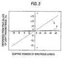
- Fig. 3 shows a graph exhibiting accuracy of the measurement when the apparatus of the above embodiment or a conventional apparatus was used.
- various spectacle lenses having different dioptric powers were used as the lens to be examined. True values of the light transmittance of these spectacle lenses were obtained by using a high accuracy spectrometer comprising an integral sphere.
- the difference from the true value (the unit: %), which is the difference a between the light transmittance obtained by using the apparatus of the present embodiment and the above true value of the light transmittance or the difference b between the light transmittance obtained by using the conventional apparatus and the above true value of the light transmittance, is taken as the coordinate and the dioptric power of the lens to be examined (the unit: dioptry) is taken as the abscissa.
- the difference from the true value b obtained by using the conventional apparatus for measuring light transmission was positive, i.e., the obtained value was greater than the true value, in the measurements of lenses having positive dioptric powers and negative, i.e., the obtained value was smaller than the true value, in the measurements of lenses having negative dioptric powers.
- the difference from the true value a obtained by using the apparatus of the present embodiment was small, i.e., the obtained value was very close to the true value obtained by using the high accuracy spectrometer comprising an integral sphere, in the measurements of lenses having dioptric powers different in a wide range.
- the high accuracy measurement could be achieved by using the apparatus of the present embodiment. It is very difficult that the accuracy shown above is obtained by using a conventional apparatus for measuring light transmittance which can be easily used.
- the above result can be obtained because the measuring light passes through the lens to be examined in a condition such that the bundle of rays of the light of measurement converges approximately on the surface of the lens to be examined and, therefore, the area of the measuring light incident into the surface of light detection in the light receiving element 50 can be held constant independently of the dioptric power of the lens to be examined.
- the sectional area of the bundle of rays of the measuring light passing through the lens to be examined can be remarkably decreased when the measuring light passes through the lens to be examined in a condition such that the bundle of rays of the measuring light converges approximately on the surface of the lens to be examined.
- the sectional area of the bundle of rays of the measuring light passing through the lens to be examined is held approximately constant by placing the point of convergence on the surface of the lens to be examined at the side of the light source.
- Figs. 4 and 5 show diagrams exhibiting modified apparatuses for measuring light transmittance as other embodiments of the present invention.
- the interference filter 40 and the hemisphere lens 60 are removed from the apparatus shown in Fig. 1.
- the hemisphere lens 60 alone is removed from the apparatus shown in Fig. 1.
- the measurement can be satisfactorily conducted by using these apparatuses when it is suitable for the object of the measurement.
- the object of the present invention can be sufficiently achieved by using the apparatuses having the modified constructions shown in Figs.
- the method for measuring light transmittance of the present invention comprises deriving light transmittance of a lens to be examined from a value corresponding to a ratio of an intensity of measuring light detected by a means for detecting light when the lens to be examined is placed in a path of the measuring light emitted from a light source and reaching the means for detecting light and the measuring light passes through the lens to be examined to an intensity of the measuring light detected by the means for detecting light when the lens to be examined is not placed in the path of the measuring light and the measuring light does not pass through the lens to be examined and is characterized in that the measuring light passes through the lens to be examined in a condition such that rays of the measuring light converge at or in a vicinity of a position where the lens to be examined is disposed.
- the apparatus of the present invention is used for the above process.
- the light transmittance of an optical lens having refractive power can be measured inexpensively and easily with excellent accuracy.
Landscapes
- Physics & Mathematics (AREA)
- General Physics & Mathematics (AREA)
- Chemical & Material Sciences (AREA)
- Analytical Chemistry (AREA)
- Testing Of Optical Devices Or Fibers (AREA)
- Investigating Or Analysing Materials By Optical Means (AREA)
- Spectrometry And Color Measurement (AREA)
- Eyeglasses (AREA)
- Photometry And Measurement Of Optical Pulse Characteristics (AREA)
Abstract
wherein the measuring light L passes through the lens 30 to be examined in a condition such that rays of the measuring light L converge at or in a vicinity of a position where the lens 30 to be examined is disposed.
Description
wherein the measuring light passes through the lens to be examined in a condition such that rays of the measuring light converge at or in a vicinity of a position where the lens to be examined is disposed.
Claims (7)
- A method for measuring light transmittance which comprises deriving light transmittance of a lens to be examined from a value corresponding to a ratio of an intensity of measuring light detected by a light detecting means when the lens to be examined is placed in a path of the measuring light emitted from a light source and reaching said light detecting means and the measuring light passes through the lens to be examined with an intensity of the measuring light detected by said light detecting means when the lens to be examined is not placed in the path of the measuring light and the measuring light does not pass through the lens to be examined,
wherein the measuring light passes through the lens to be examined in a condition such that rays of the measuring light converge at or in a vicinity of a position where the lens to be examined is disposed. - A method for measuring light transmittance according to Claim 1, wherein the rays of the measuring light converge on a surface of the lens to be examined at a side of the light source.
- An apparatus for measuring light transmittance which comprises a light source emitting a measuring light, a light detector for detecting the light of measurement, an apparatus for holding a lens to be examined which is disposed between the light source and the light detector and can hold or release the lens to be examined as desired and a first convergence lens through which rays of the measuring light converge at or in a vicinity of a position where the lens to be examined is disposed.
- An apparatus for measuring light transmittance according to Claim 3, wherein the rays of the measuring light of converge on a surface of the lens to be examined at a side of the light source through the first convergence lens.
- An apparatus for measuring light transmittance according to Claim 3 or 4, which further comprises a second convergence lens which is disposed between the apparatus for holding a lens to be examined and the light detector and sends the rays of the measuring light into the light detector in a condition such that the rays converge.
- An apparatus for measuring light transmittance according to any one of Claims 3, 4 and 5, which further comprises a interference filter which is disposed on a path of rays of the measuring light and transmits mostly light having a wavelength within a specific range.
- An apparatus for measuring light transmittance which comprises a plurality of apparatuses for measuring light transmittance described in Claim 6 so that light transmittance can be measured in a plurality of specific ranges of wavelength of light.
Applications Claiming Priority (2)
| Application Number | Priority Date | Filing Date | Title |
|---|---|---|---|
| JP2001072766 | 2001-03-14 | ||
| JP2001072766A JP3814155B2 (en) | 2001-03-14 | 2001-03-14 | Transmittance measuring method and apparatus |
Publications (3)
| Publication Number | Publication Date |
|---|---|
| EP1241461A2 true EP1241461A2 (en) | 2002-09-18 |
| EP1241461A3 EP1241461A3 (en) | 2003-07-30 |
| EP1241461B1 EP1241461B1 (en) | 2006-06-07 |
Family
ID=18930303
Family Applications (1)
| Application Number | Title | Priority Date | Filing Date |
|---|---|---|---|
| EP02004958A Expired - Lifetime EP1241461B1 (en) | 2001-03-14 | 2002-03-05 | Method for measuring light transmittance of lenses and apparatus therefor |
Country Status (7)
| Country | Link |
|---|---|
| US (1) | US6816246B2 (en) |
| EP (1) | EP1241461B1 (en) |
| JP (1) | JP3814155B2 (en) |
| KR (1) | KR100474864B1 (en) |
| CN (1) | CN100354620C (en) |
| AT (1) | ATE329242T1 (en) |
| DE (1) | DE60211986T2 (en) |
Cited By (3)
| Publication number | Priority date | Publication date | Assignee | Title |
|---|---|---|---|---|
| EP1568984A3 (en) * | 2004-02-27 | 2006-02-08 | Nidek Co., Ltd. | Lens meter |
| WO2022115422A1 (en) | 2020-11-24 | 2022-06-02 | Applied Materials, Inc. | Optical resolution measurement method for optical devices |
| EP4229385A4 (en) * | 2020-10-15 | 2024-10-16 | Applied Materials, Inc. | TRANSPARENCY METROLOGY SYSTEMS, APPARATUSES AND METHODS FOR OPTICAL DEVICES |
Families Citing this family (16)
| Publication number | Priority date | Publication date | Assignee | Title |
|---|---|---|---|---|
| KR100681693B1 (en) * | 2005-10-21 | 2007-02-09 | 재단법인 포항산업과학연구원 | Optical disturbance isolation system and method for radiation temperature instrument |
| JP2012047732A (en) * | 2010-07-30 | 2012-03-08 | Hoya Corp | Transmittance measuring instrument, photomask transmittance inspection device, transmittance inspection method, photomask manufacturing method, pattern transfer method, and photomask product |
| CN102455290B (en) * | 2010-10-18 | 2013-03-27 | 北京众智同辉科技有限公司 | Testing method of electro-induced liquid crystal frost glass optical inhomogeneity |
| KR20120077330A (en) * | 2010-12-30 | 2012-07-10 | 삼성코닝정밀소재 주식회사 | Apparatus for measuring the degree of transmission of a patterned glass substrate |
| CN103018213B (en) * | 2011-09-26 | 2015-04-15 | 同济大学 | Method and device for measuring wide spectral transmittance in 0-70-degree incidence of optical film |
| CN103926054A (en) * | 2013-01-15 | 2014-07-16 | 上海雄博精密仪器股份有限公司 | Common optical path collection device for measuring vertex power and UV transmissivity of spectacle lens simultaneously |
| CN104111238A (en) * | 2013-04-16 | 2014-10-22 | 烁光特晶科技有限公司 | Optical material transmittance testing system and testing method thereof |
| CN104207787B (en) * | 2014-09-28 | 2016-06-29 | 广州视源电子科技股份有限公司 | Human body identification method |
| CN104236864B (en) * | 2014-09-29 | 2017-09-26 | 大连耐斯特科技发展有限公司 | Glasses detection instrument |
| US9733567B2 (en) * | 2014-09-30 | 2017-08-15 | Sii Semiconductor Corporation | Reticle transmittance measurement method, and projection exposure method using the same |
| CN105628346B (en) * | 2016-04-05 | 2019-05-21 | 中国工程物理研究院激光聚变研究中心 | Lens transmittance test system and method |
| US10859494B2 (en) * | 2018-09-03 | 2020-12-08 | Chongqing Hkc Optoelectronics Technology Co., Ltd. | Transmittance measuring method, device and computer readable storage medium |
| US10908065B2 (en) * | 2018-09-17 | 2021-02-02 | Inguran, Llc | Light collection from objects within a fluid column |
| CN112763187B (en) * | 2020-11-30 | 2022-10-14 | 青岛歌尔声学科技有限公司 | Transmission optical performance testing system and method of film material based on telephoto optical path |
| CN117470026A (en) * | 2023-11-22 | 2024-01-30 | 西安北方光电科技防务有限公司 | A detection device and measurement method for the transmittance of a gunner's sight |
| CN119164898B (en) * | 2024-11-08 | 2026-04-21 | 深圳市锦兆电子科技股份有限公司 | Spectroscopic testing methods and systems for lens assemblies |
Family Cites Families (13)
| Publication number | Priority date | Publication date | Assignee | Title |
|---|---|---|---|---|
| US3904294A (en) * | 1973-12-28 | 1975-09-09 | Polaroid Corp | Automatic lens testing apparatus |
| JPS5720636A (en) * | 1980-07-12 | 1982-02-03 | Olympus Optical Co Ltd | Measuring device for transmittance of lens |
| US4611913A (en) * | 1982-04-19 | 1986-09-16 | Sugino Paul S | Method and apparatus for analyzing ophthalmic elements and the like |
| US4549081A (en) * | 1984-03-15 | 1985-10-22 | Ace Sophisticates, Inc. | Spectrophotometer for measuring absorption characteristics of a complex lens |
| FR2654513B1 (en) * | 1989-11-10 | 1993-07-16 | Essilor Int | METHOD AND DEVICE FOR DETERMINING THE CHARACTERISTICS OF A LENS, AND IN PARTICULAR OF ITS POWER. |
| TW283201B (en) * | 1993-08-13 | 1996-08-11 | Ricoh Kk | |
| JPH0792084A (en) * | 1993-09-24 | 1995-04-07 | Asahi Glass Co Ltd | Optical system transmittance measuring device and measuring method |
| US6072570A (en) * | 1997-07-24 | 2000-06-06 | Innotech | Image quality mapper for progressive eyeglasses |
| JP3871415B2 (en) * | 1997-11-06 | 2007-01-24 | 株式会社トプコン | Spectral transmittance measuring device |
| JPH11211617A (en) * | 1998-01-22 | 1999-08-06 | Topcon Corp | Lens identification device |
| JP3762120B2 (en) * | 1998-10-20 | 2006-04-05 | 株式会社トーメーコーポレーション | Lens meter |
| KR20000000411A (en) * | 1999-10-20 | 2000-01-15 | 강정근 | The Light Explorer that is using lens to generate a straight ray |
| US6577387B2 (en) * | 2000-12-29 | 2003-06-10 | Johnson & Johnson Vision Care, Inc. | Inspection of ophthalmic lenses using absorption |
-
2001
- 2001-03-14 JP JP2001072766A patent/JP3814155B2/en not_active Expired - Fee Related
-
2002
- 2002-03-05 EP EP02004958A patent/EP1241461B1/en not_active Expired - Lifetime
- 2002-03-05 DE DE60211986T patent/DE60211986T2/en not_active Expired - Lifetime
- 2002-03-05 AT AT02004958T patent/ATE329242T1/en not_active IP Right Cessation
- 2002-03-07 KR KR10-2002-0012100A patent/KR100474864B1/en not_active Expired - Fee Related
- 2002-03-08 US US10/092,442 patent/US6816246B2/en not_active Expired - Fee Related
- 2002-03-13 CN CNB021071837A patent/CN100354620C/en not_active Expired - Fee Related
Cited By (8)
| Publication number | Priority date | Publication date | Assignee | Title |
|---|---|---|---|---|
| EP1568984A3 (en) * | 2004-02-27 | 2006-02-08 | Nidek Co., Ltd. | Lens meter |
| US7209224B2 (en) | 2004-02-27 | 2007-04-24 | Nidek Co., Ltd. | Lens meter |
| EP4229385A4 (en) * | 2020-10-15 | 2024-10-16 | Applied Materials, Inc. | TRANSPARENCY METROLOGY SYSTEMS, APPARATUSES AND METHODS FOR OPTICAL DEVICES |
| US12229940B2 (en) | 2020-10-15 | 2025-02-18 | Applied Materials, Inc. | In-line metrology systems, apparatus, and methods for optical devices |
| US12236575B2 (en) | 2020-10-15 | 2025-02-25 | Applied Materials, Inc. | In-line metrology systems, apparatus, and methods for optical devices |
| WO2022115422A1 (en) | 2020-11-24 | 2022-06-02 | Applied Materials, Inc. | Optical resolution measurement method for optical devices |
| EP4251964A4 (en) * | 2020-11-24 | 2024-10-16 | Applied Materials, Inc. | METHOD FOR MEASURING OPTICAL RESOLUTIONS FOR OPTICAL DEVICES |
| US12165341B2 (en) | 2020-11-24 | 2024-12-10 | Applied Materials, Inc. | Optical resolution measurement method for optical devices |
Also Published As
| Publication number | Publication date |
|---|---|
| DE60211986T2 (en) | 2007-03-01 |
| EP1241461A3 (en) | 2003-07-30 |
| JP2002277348A (en) | 2002-09-25 |
| JP3814155B2 (en) | 2006-08-23 |
| KR100474864B1 (en) | 2005-03-09 |
| CN1375690A (en) | 2002-10-23 |
| DE60211986D1 (en) | 2006-07-20 |
| KR20020073255A (en) | 2002-09-23 |
| US20020131038A1 (en) | 2002-09-19 |
| EP1241461B1 (en) | 2006-06-07 |
| CN100354620C (en) | 2007-12-12 |
| ATE329242T1 (en) | 2006-06-15 |
| US6816246B2 (en) | 2004-11-09 |
Similar Documents
| Publication | Publication Date | Title |
|---|---|---|
| EP1241461B1 (en) | Method for measuring light transmittance of lenses and apparatus therefor | |
| US5745234A (en) | Variable angle reflectometer employing an integrating sphere and a light concentrator | |
| US20110109907A1 (en) | Optical sensor system and method of sensing | |
| DE60018540D1 (en) | Wavefront sensor with multifocal Hartmann plate and its use in a lens measuring device or an active optical reflection telescope | |
| EP0334536B1 (en) | Particle measuring apparatus | |
| JPH07509315A (en) | Spectrometer for Renzometer | |
| JP2015504524A (en) | Support, apparatus and method for performing spectacle lens reflection measurements | |
| US4893929A (en) | Particle analyzing apparatus | |
| JPS6465430A (en) | Manufacture of measuring device and fiber for transparent object and fiber manufactured thereby | |
| CN206399566U (en) | Glass surface stress detection device and the detection prism for it | |
| US20070222987A1 (en) | Optical Design of a Particulate measurement system | |
| EP2573546A1 (en) | Gas sensor | |
| KR840002359B1 (en) | Infrared film thickness meter | |
| CN112437871B (en) | System and method for real-time high-precision measurement of atmospheric attenuation of electromagnetic radiation from at least one source | |
| CN218481439U (en) | Glasses optical lens piece defect detecting device | |
| CN106908144A (en) | A kind of ultraweak starlight illumination measurement apparatus and method | |
| RU2460988C1 (en) | Method of measuring particle size distribution in wide range of concentrations and apparatus for realising said method (versions) | |
| US4494869A (en) | Apparatus and method for photometric measurement of oil present on human skin | |
| RU2202814C1 (en) | Cat's eye index meter for optoelectronic devices | |
| CN114414063A (en) | Double-focusing infrared high-temperature measuring device | |
| CN115307736B (en) | Light collecting system of spectrocolorimeter | |
| JP7633245B2 (en) | Optical power meter for safe operation of optical wireless power systems | |
| CN104101481A (en) | Lens scattered light detector with dual optical paths | |
| KR101456273B1 (en) | Optical system for measurement gas | |
| JPH11326125A (en) | Auto-lens meter |
Legal Events
| Date | Code | Title | Description |
|---|---|---|---|
| PUAI | Public reference made under article 153(3) epc to a published international application that has entered the european phase |
Free format text: ORIGINAL CODE: 0009012 |
|
| AK | Designated contracting states |
Kind code of ref document: A2 Designated state(s): AT BE CH CY DE DK ES FI FR GB GR IE IT LI LU MC NL PT SE TR |
|
| AX | Request for extension of the european patent |
Free format text: AL;LT;LV;MK;RO;SI |
|
| PUAL | Search report despatched |
Free format text: ORIGINAL CODE: 0009013 |
|
| AK | Designated contracting states |
Designated state(s): AT BE CH CY DE DK ES FI FR GB GR IE IT LI LU MC NL PT SE TR |
|
| AX | Request for extension of the european patent |
Extension state: AL LT LV MK RO SI |
|
| 17P | Request for examination filed |
Effective date: 20040130 |
|
| AKX | Designation fees paid |
Designated state(s): AT BE CH CY DE DK ES FI FR GB GR IE IT LI LU MC NL PT SE TR |
|
| GRAP | Despatch of communication of intention to grant a patent |
Free format text: ORIGINAL CODE: EPIDOSNIGR1 |
|
| GRAS | Grant fee paid |
Free format text: ORIGINAL CODE: EPIDOSNIGR3 |
|
| GRAA | (expected) grant |
Free format text: ORIGINAL CODE: 0009210 |
|
| AK | Designated contracting states |
Kind code of ref document: B1 Designated state(s): AT BE CH CY DE DK ES FI FR GB GR IE IT LI LU MC NL PT SE TR |
|
| PG25 | Lapsed in a contracting state [announced via postgrant information from national office to epo] |
Ref country code: IT Free format text: LAPSE BECAUSE OF FAILURE TO SUBMIT A TRANSLATION OF THE DESCRIPTION OR TO PAY THE FEE WITHIN THE PRESCRIBED TIME-LIMIT;WARNING: LAPSES OF ITALIAN PATENTS WITH EFFECTIVE DATE BEFORE 2007 MAY HAVE OCCURRED AT ANY TIME BEFORE 2007. THE CORRECT EFFECTIVE DATE MAY BE DIFFERENT FROM THE ONE RECORDED. Effective date: 20060607 Ref country code: CH Free format text: LAPSE BECAUSE OF FAILURE TO SUBMIT A TRANSLATION OF THE DESCRIPTION OR TO PAY THE FEE WITHIN THE PRESCRIBED TIME-LIMIT Effective date: 20060607 Ref country code: FI Free format text: LAPSE BECAUSE OF FAILURE TO SUBMIT A TRANSLATION OF THE DESCRIPTION OR TO PAY THE FEE WITHIN THE PRESCRIBED TIME-LIMIT Effective date: 20060607 Ref country code: AT Free format text: LAPSE BECAUSE OF FAILURE TO SUBMIT A TRANSLATION OF THE DESCRIPTION OR TO PAY THE FEE WITHIN THE PRESCRIBED TIME-LIMIT Effective date: 20060607 Ref country code: LI Free format text: LAPSE BECAUSE OF FAILURE TO SUBMIT A TRANSLATION OF THE DESCRIPTION OR TO PAY THE FEE WITHIN THE PRESCRIBED TIME-LIMIT Effective date: 20060607 Ref country code: BE Free format text: LAPSE BECAUSE OF FAILURE TO SUBMIT A TRANSLATION OF THE DESCRIPTION OR TO PAY THE FEE WITHIN THE PRESCRIBED TIME-LIMIT Effective date: 20060607 |
|
| REG | Reference to a national code |
Ref country code: GB Ref legal event code: FG4D |
|
| REG | Reference to a national code |
Ref country code: CH Ref legal event code: EP |
|
| REG | Reference to a national code |
Ref country code: IE Ref legal event code: FG4D |
|
| REF | Corresponds to: |
Ref document number: 60211986 Country of ref document: DE Date of ref document: 20060720 Kind code of ref document: P |
|
| PG25 | Lapsed in a contracting state [announced via postgrant information from national office to epo] |
Ref country code: SE Free format text: LAPSE BECAUSE OF FAILURE TO SUBMIT A TRANSLATION OF THE DESCRIPTION OR TO PAY THE FEE WITHIN THE PRESCRIBED TIME-LIMIT Effective date: 20060907 Ref country code: DK Free format text: LAPSE BECAUSE OF FAILURE TO SUBMIT A TRANSLATION OF THE DESCRIPTION OR TO PAY THE FEE WITHIN THE PRESCRIBED TIME-LIMIT Effective date: 20060907 |
|
| PG25 | Lapsed in a contracting state [announced via postgrant information from national office to epo] |
Ref country code: ES Free format text: LAPSE BECAUSE OF FAILURE TO SUBMIT A TRANSLATION OF THE DESCRIPTION OR TO PAY THE FEE WITHIN THE PRESCRIBED TIME-LIMIT Effective date: 20060918 |
|
| PG25 | Lapsed in a contracting state [announced via postgrant information from national office to epo] |
Ref country code: PT Free format text: LAPSE BECAUSE OF FAILURE TO SUBMIT A TRANSLATION OF THE DESCRIPTION OR TO PAY THE FEE WITHIN THE PRESCRIBED TIME-LIMIT Effective date: 20061107 |
|
| REG | Reference to a national code |
Ref country code: CH Ref legal event code: PL |
|
| ET | Fr: translation filed | ||
| PLBE | No opposition filed within time limit |
Free format text: ORIGINAL CODE: 0009261 |
|
| STAA | Information on the status of an ep patent application or granted ep patent |
Free format text: STATUS: NO OPPOSITION FILED WITHIN TIME LIMIT |
|
| 26N | No opposition filed |
Effective date: 20070308 |
|
| PG25 | Lapsed in a contracting state [announced via postgrant information from national office to epo] |
Ref country code: IE Free format text: LAPSE BECAUSE OF NON-PAYMENT OF DUE FEES Effective date: 20070305 Ref country code: MC Free format text: LAPSE BECAUSE OF NON-PAYMENT OF DUE FEES Effective date: 20070331 |
|
| PG25 | Lapsed in a contracting state [announced via postgrant information from national office to epo] |
Ref country code: GR Free format text: LAPSE BECAUSE OF FAILURE TO SUBMIT A TRANSLATION OF THE DESCRIPTION OR TO PAY THE FEE WITHIN THE PRESCRIBED TIME-LIMIT Effective date: 20060908 |
|
| PG25 | Lapsed in a contracting state [announced via postgrant information from national office to epo] |
Ref country code: CY Free format text: LAPSE BECAUSE OF FAILURE TO SUBMIT A TRANSLATION OF THE DESCRIPTION OR TO PAY THE FEE WITHIN THE PRESCRIBED TIME-LIMIT Effective date: 20060607 Ref country code: LU Free format text: LAPSE BECAUSE OF NON-PAYMENT OF DUE FEES Effective date: 20070305 |
|
| PG25 | Lapsed in a contracting state [announced via postgrant information from national office to epo] |
Ref country code: TR Free format text: LAPSE BECAUSE OF FAILURE TO SUBMIT A TRANSLATION OF THE DESCRIPTION OR TO PAY THE FEE WITHIN THE PRESCRIBED TIME-LIMIT Effective date: 20060607 |
|
| PGFP | Annual fee paid to national office [announced via postgrant information from national office to epo] |
Ref country code: GB Payment date: 20130228 Year of fee payment: 12 Ref country code: DE Payment date: 20130227 Year of fee payment: 12 Ref country code: FR Payment date: 20130325 Year of fee payment: 12 |
|
| PGFP | Annual fee paid to national office [announced via postgrant information from national office to epo] |
Ref country code: NL Payment date: 20130316 Year of fee payment: 12 |
|
| REG | Reference to a national code |
Ref country code: DE Ref legal event code: R119 Ref document number: 60211986 Country of ref document: DE |
|
| REG | Reference to a national code |
Ref country code: NL Ref legal event code: V1 Effective date: 20141001 |
|
| GBPC | Gb: european patent ceased through non-payment of renewal fee |
Effective date: 20140305 |
|
| REG | Reference to a national code |
Ref country code: FR Ref legal event code: ST Effective date: 20141128 |
|
| REG | Reference to a national code |
Ref country code: DE Ref legal event code: R119 Ref document number: 60211986 Country of ref document: DE Effective date: 20141001 |
|
| PG25 | Lapsed in a contracting state [announced via postgrant information from national office to epo] |
Ref country code: GB Free format text: LAPSE BECAUSE OF NON-PAYMENT OF DUE FEES Effective date: 20140305 Ref country code: DE Free format text: LAPSE BECAUSE OF NON-PAYMENT OF DUE FEES Effective date: 20141001 Ref country code: FR Free format text: LAPSE BECAUSE OF NON-PAYMENT OF DUE FEES Effective date: 20140331 |
|
| PG25 | Lapsed in a contracting state [announced via postgrant information from national office to epo] |
Ref country code: NL Free format text: LAPSE BECAUSE OF NON-PAYMENT OF DUE FEES Effective date: 20141001 |