EP1241452A2 - Method for determining the filling level of a tank in motor vehicles - Google Patents
Method for determining the filling level of a tank in motor vehicles Download PDFInfo
- Publication number
- EP1241452A2 EP1241452A2 EP02003875A EP02003875A EP1241452A2 EP 1241452 A2 EP1241452 A2 EP 1241452A2 EP 02003875 A EP02003875 A EP 02003875A EP 02003875 A EP02003875 A EP 02003875A EP 1241452 A2 EP1241452 A2 EP 1241452A2
- Authority
- EP
- European Patent Office
- Prior art keywords
- level
- value
- motor vehicle
- level value
- tank
- Prior art date
- Legal status (The legal status is an assumption and is not a legal conclusion. Google has not performed a legal analysis and makes no representation as to the accuracy of the status listed.)
- Withdrawn
Links
Images


Classifications
-
- G—PHYSICS
- G01—MEASURING; TESTING
- G01F—MEASURING VOLUME, VOLUME FLOW, MASS FLOW OR LIQUID LEVEL; METERING BY VOLUME
- G01F9/00—Measuring volume flow relative to another variable, e.g. of liquid fuel for an engine
- G01F9/008—Measuring volume flow relative to another variable, e.g. of liquid fuel for an engine where the other variable is the flight or running time
-
- G—PHYSICS
- G01—MEASURING; TESTING
- G01F—MEASURING VOLUME, VOLUME FLOW, MASS FLOW OR LIQUID LEVEL; METERING BY VOLUME
- G01F23/00—Indicating or measuring liquid level or level of fluent solid material, e.g. indicating in terms of volume or indicating by means of an alarm
- G01F23/80—Arrangements for signal processing
- G01F23/802—Particular electronic circuits for digital processing equipment
- G01F23/804—Particular electronic circuits for digital processing equipment containing circuits handling parameters other than liquid level
Definitions
- level measuring devices are used to measure the level of the fuel (petrol, diesel ...) in the fuel tank.
- the current level will be communicated to the motor vehicle driver via a display, so that he has the expected range of the motor vehicle with the fuel remaining in the tank and the need to fill up the tank.
- Level measuring devices for tanks have been known for more than 20 years, in which the Buoyancy body of a rotatably mounted float in the area of the liquid level the liquid in the tank in question is floating.
- the axis of rotation of the Float which is usually below the highest possible liquid level connected to the input side of a mechanical transmission, on the output side a magnet is mounted.
- the angular position depending on the level of the liquid the float is thus transferred to the magnet, the angular position of which is a The measure of the level is.
- the magnet is located near the outside of the tank. Its rotational position is in older embodiments of the known level measuring device through a housing wall through a second rotatably mounted Detected magnet, which is mechanically coupled to a display device.
- This level measuring device is suitable for tanks in which flammable or explosive Liquids are stored. Because with the gearbox that is in the potentially explosive area is arranged is not a problematic implementation with regard to its tightness required by the tank wall.
- the magnet stored outside the tank interior replaced a magnetic field sensor, which is connected to an electronic evaluation device is. This sensor detects the magnetic field depending on the angular position of the magnet, which is a measure of the level and with the help of the evaluation device into one Level value can be converted.
- DE 199 25 185 A1 relates to a level measuring device for a tank with a an axis of rotation rotatably mounted float and with a first end and one second end tube which is set up with its second end to reach the outside of the tank and sealed against the interior of the tank is.
- a magnet is attached to the float.
- a magnetic field sensor is arranged, which is set up to one of the angular position of the float-dependent signal via an electrical line to an evaluation device issue.
- DE 40 25 184 A1 relates to a sensor for detecting the acceleration or inclination, especially for motor vehicles. It has a cylindrical liquid container, in which there is an electrically conductive liquid. Protrude into the liquid container from below two electrodes, which are coated with a dielectric. The electrodes and the conductive liquid work as a condenser. From the capacities of these capacitors the position of the sensor and thus its inclination is determined.
- acceleration sensors are known in the prior art. According to the automotive paperback, Bosch, 23rd edition, Viehweg Verlag (1999), pages 103 to 109, the following sensors are suitable, for example, for detecting corner accelerations and changes in speed: inductive sensors, Hall sensors, micromechanical silicon rotation rate sensors, Hall acceleration sensors, piezoelectric sensors or capacitive silicon acceleration sensors.
- the current fill level means that at a certain point in time portion of the tank volume filled with fuel.
- the initial level is the one Level, which is immediately after the start of the motor vehicle engine with the level measuring device measured level is determined and then as an input value is used for the subsequent process steps until there is a new input value results.
- the level measuring device may be a conventional one in the prior art act used level measuring device for a tank.
- a level measuring device is conceivable which contains a float rotatably mounted about an axis of rotation, its angular position, for example with the help of a magnet and a magnetic field sensor or is determined using a potentiometer.
- Level sensors are also used conceivable, the capacitance or resistance between arranged in the tank Measure electrodes.
- any other are for the present invention Types of level measuring device suitable.
- the consumption value of the motor vehicle lies in engines with fuel injection in the prior art.
- a window around a level value means an area around the level value, i.e. a range of values that in each case contains the level value itself, but also includes larger and / or smaller values surrounding the level value.
- the display of the new input value as the current fill level can be done by a the technology already existing in the motor vehicle level indicator. It can are, for example, an analog display that is in the driver information area of the motor vehicle, possibly as part of the instrument cluster.
- the advantages of the method according to the invention can be seen in the fact that the accuracy the level indicator is increased and that a more precise determination of the range of the Motor vehicle is possible.
- the accuracy is mainly increased by the fact that the State of the art existing influence of the dynamics of the tank content on the display, especially when sloshing and cornering is eliminated.
- Another The advantage is that inaccuracies in the residual quantity range due to the Floats of the level measuring device can occur on the tank bottom, largely be eliminated. It is also advantageous that those required to use the method Measuring devices, sensors and computers already exist in the motor vehicle are. Required extensions of the previous fuel gauge only appear in the form of Software on, hardware is also not required, which in turn has a positive effect on the Cost of the procedure affects.
- the fill level of the tank at the start of the motor vehicle engine can therefore be from a the fill level measured above can be determined. It can be assumed that the motor vehicle is at the start of the motor vehicle engine not moved and thus errors in the measured level due to the dynamics of the Tank contents can be excluded. Furthermore, the level can be determined at the start of the motor vehicle engine a correction with the level measuring device measured starting fill level, in particular measurement errors that are due to the inclination or inclination of the motor vehicle. By an inclination or An inclination of the motor vehicle is followed by an inclination or inclination of the fuel surface in the tank, which can lead to a distortion of the measured level.
- the Correction of the measured fill level can be carried out according to an embodiment of the invention with the help of vehicle location information. These can be the inclination or incline of the motor vehicle, these two sizes by at least one sensor can be detected. Sensors for the detection of motor vehicle position information are already integrated in the motor vehicle in the prior art.
- the correction of the The measured fill level is preferably carried out with the aid of the position of the motor vehicle and / or Acceleration information.
- the vehicle location information can include the inclination or incline of the motor vehicle, these two Sizes are detected by at least one sensor.
- the sensors required for Detection of the vehicle position and acceleration information are in modern Vehicles already included, for example those for vehicle dynamics systems such as ESP or for the headlamp leveling required vehicle position or acceleration sensors.
- the influence of the vehicle position and acceleration on the level measuring device can be corrected using correction algorithms.
- the correction algorithms are based among other things on the knowledge of the course of the measured by the level measuring device Level depending on the vehicle position and the acceleration.
- the information about the current consumption is for engines with fuel injection already before.
- the instantaneous consumption is integrated in order to know the absolute consumption, which is subtracted from the input value to calculate the second level value.
- the input value is either the measured (and possibly corrected) level directly after the start of the vehicle or the last time on the level indicator displayed level.
- the window is calculated from the error in the consumption calculation. This error increases due to the accumulation of small sizes (integration) over time. This window then defines the area in which the fill level of the Motor vehicle tanks located real. It is limited by the maximum and the minimum possible level, which results from the largest possible error.
- the first level value is the new input value, if the first Level value in the window is around the second level value and that the second level value the new input value is if the first level value is outside the window around the second level value.
- the window is the next The procedure is very small because the level value is assumed to be exact and the calculation of the absolute consumption is based on this new "exact" input value.
- the window becomes larger the next time the process is run the integration of the current consumption is continued and the error thereby increased. The resulting error that increases over time from the consumption calculation is due to the combination with the corrected measured value of the level measuring device kept as low as possible.
- the measured values of the level measuring device, the inclination and inclination sensors, the acceleration sensors and the Combined sensors for the determination of instantaneous consumption is that the extension of a modern motor vehicle to carry out the method according to the invention only in Form of software is required. Hardware is also not required because the required Components in the prior art are already present in the motor vehicle.
- the Required calculations and correction algorithms can already be done in the vehicle located computers, for example the engine control unit or the control unit of the Combi instruments are carried out.
- the level of the motor vehicle tank is indicated to the driver of the motor vehicle via suitable ones Display instruments that are connected to the computers mentioned above.
- the display is digital Display. This was previously not possible in the prior art because the level displayed fluctuated too much, making a digital display bad would have been readable. In the more accurate determined according to the present invention Level, the fluctuations are greatly reduced and therefore is a digital display possible.
- the range of a motor vehicle is to be understood as the way that can be driven with the fuel remaining in the motor vehicle tank.
- the correction of the level measurement errors resulting from the vehicle position can alternatively to the methods described above by skillfully installing one or more fuel level sensors as a level measuring device.
- a centrally arranged tank level sensor serves as a level measuring device. It is advantageous that there is an inclination of the fuel surface has the least impact on the measured level at the central point.
- a Another embodiment of the invention serve in a saddle tank at least two in Tank level sensor arranged in both chambers as a level measuring device.
- the invention further relates to the use of the method according to the invention for Checking the function of the level measuring device, with each pass of the Procedure after comparing the first level with the window around the second Level value is checked how often the first level value within the window lies. If the first level value is often in the window, the calculated level is correct and the level measured by the level measuring device often coincides with the level measuring device works. If the values rarely match, it can be assumed that the level measuring device is defective.
- Figure 1 shows a flow chart of a method according to the invention.
- the start fill level 2 in the motor vehicle tank is measured by a fill level measuring device 3.
- the measured start fill level F S is corrected 4 on the basis of motor vehicle position information, from which the initial fill level F A results, which is the input value F E serves.
- the input value F E can be passed on to the fill level indicator 7 so that it displays the input value F E as the current fill level.
- the calculation 6 of the second fill level value F 2 can be carried out from the input value F E and by integrating the instantaneous consumption 5.
- a window ⁇ F around the second fill level value F 2 is formed from the error ⁇ F of the consumption V, which results from the integration of the instantaneous consumption 8.
- the first fill level value F 1 is determined, by measuring the fill level 9 with a fill level measuring device, correcting 10 the measured fill level F G on the basis of vehicle position and acceleration information (F K ) and by forming the moving average 11 (F M ).
- the calculated moving average F M is the first level value F 1 .
- it is checked whether the first fill level value F 1 lies in the window ⁇ F. In the first case 13, the first fill level value F 1 is not in the window ⁇ F and the second fill level value F 2 serves as the new input value F E (F E F 2 ) 15.
- the level indicator 7 shows the new input value F E as the current level.
- Figure 2 shows the basic arrangement for implementing the method according to the invention based on a multi-sensor concept.
- a fill level measuring device 3 sensors for determining the instantaneous consumption 20, inclination and inclination sensors 21 and acceleration sensors 22 are connected to an information path 23 present in the motor vehicle, for example a CAN bus.
- the measured values of the sensors that is to say measured fill level F G , instantaneous consumption V m , inclination and inclination information I N, S and / or acceleration information I B are passed on to computer 24 via information path 23.
- the computer 24 can be, for example, a control unit of the instrument cluster or the engine control.
- the computer 24 carries out the necessary calculations and correction algorithms. This includes the correction of the level F G measured with the level measuring device 3 on the basis of the inclination / inclination and / or acceleration information (I N, S , I B ).
- the computer 24 It is also the task of the computer 24 to form the moving average value F M. Furthermore, the computer 24 is used to integrate the instantaneous consumption V m and to calculate the second fill level F 2 and the window ⁇ F. After the case distinction 12 has taken place, a new input value F E and possibly the calculated range R are passed on from the computer 24 via the information path 23 to the level indicator (or the range indicator) 25.
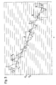
- FIG. 3 shows an example of the fill level curve determined by the method according to the invention.
- the course of the corrected level F K measured with the level measuring device and the input value F E indicated by the level indicator are shown as a function of time t.
- the corrected measured level F K shows significant fluctuations in the order of magnitude of several liters. These fluctuations are a consequence of the dynamics of the tank content.
- the input value F E resulting from the method according to the invention which is communicated to the motor vehicle driver via the fill level indicator, is significantly smoother. Many intersections of the input value F E with the corrected measured fill level F K can be seen.
- the input value F E indicated by the level indicator achieves an accuracy of +/- 11.
- the influence of the dynamics of the tank content on the corrected measured level F K in particular in sloshing and cornering is eliminated by the method according to the invention, in particular by taking into account the current consumption.
- FIG. 4 shows the enlarged section A from FIG. 3.
- the window ⁇ F widens clearly around F 2 , since the errors increase due to the integration of the instantaneous consumption.
- the second level value F 2 is accepted as the input value F E , the errors increase.
- the first fill level value F 1 adopted as the input value F E and the error in consumption is set to zero. This can be clearly seen at point X.
- the width of the window ⁇ F is again set to zero at this point X.
Abstract
Description
In modernen Kraftfahrzeugen dienen Füllstandmeßvorrichtungen zur Erfassung des Füllstands des Kraftstoffs (Benzin, Diesel...) in dem Kraftstofftank. Der aktuelle Füllstand wird dem Kraftfahrzeugfahrer über eine Anzeige mitgeteilt, so daß er die zu erwartende Reichweite des Kraftfahrzeugs mit dem im Tank verbleibenden Kraftstoff und die Notwendigkeit, den Tank aufzufüllen, einschätzen kann.In modern motor vehicles, level measuring devices are used to measure the level of the fuel (petrol, diesel ...) in the fuel tank. The current level will be communicated to the motor vehicle driver via a display, so that he has the expected range of the motor vehicle with the fuel remaining in the tank and the need to fill up the tank.
Seit mehr als 20 Jahren sind Füllstandmeßvorrichtungen für Tanks bekannt, bei denen der Auftriebskörper eines drehbar gelagerten Schwimmers im Bereich des Flüssigkeitsspiegels der in dem betreffenden Tank befindlichen Flüssigkeit schwimmt. Die Drehachse des Schwimmers, die in der Regel unterhalb des höchstmöglichen Flüssigkeitsstandes liegt, ist mit der Eingangsseite eines mechanischen Getriebes verbunden, an dessen Ausgangsseite ein Magnet montiert ist. Die von dem Füllstand der Flüssigkeit abhängende Winkelstellung des Schwimmers wird so auf den Magneten übertragen, dessen Winkelstellung somit ein Maß für den Füllstand ist. Der Magnet befindet sich in der Nähe der Außenseite des Tanks. Seine Drehstellung wird bei älteren Ausführungsformen der vorbekannten Füllstandmeßvorrichtung durch eine Gehäusewandung hindurch von einem zweiten drehbar gelagerten Magneten erfaßt, der mechanisch mit einer Anzeigeeinrichtung gekoppelt ist. Diese Füllstandmeßvorrichtung eignet sich für Tanks, in denen brennbare oder explosionsgefährdete Flüssigkeiten gelagert werden. Denn bei dem Getriebe, das im explosionsgefährdeten Bereich angeordnet ist, ist keine hinsichtlich ihrer Dichtheit problematische Durchführung durch die Tankwandung erforderlich. In späteren Ausführungsformen der vorbekannten Füllstandmeßvorrichtung ist der außerhalb des Tankinnenraums gelagerte Magnet durch einen Magnetfeldsensor ersetzt, der mit einer elektronischen Auswerteeinrichtung verbunden ist. Dieser Sensor erfaßt das von der Winkelstellung des Magneten abhängende Magnetfeld, das ein Maß für den Füllstand ist und mit Hilfe der Auswerteeinrichtung in einen Füllstandwert umgewandelt werden kann.Level measuring devices for tanks have been known for more than 20 years, in which the Buoyancy body of a rotatably mounted float in the area of the liquid level the liquid in the tank in question is floating. The axis of rotation of the Float, which is usually below the highest possible liquid level connected to the input side of a mechanical transmission, on the output side a magnet is mounted. The angular position depending on the level of the liquid the float is thus transferred to the magnet, the angular position of which is a The measure of the level is. The magnet is located near the outside of the tank. Its rotational position is in older embodiments of the known level measuring device through a housing wall through a second rotatably mounted Detected magnet, which is mechanically coupled to a display device. This level measuring device is suitable for tanks in which flammable or explosive Liquids are stored. Because with the gearbox that is in the potentially explosive area is arranged is not a problematic implementation with regard to its tightness required by the tank wall. In later embodiments of the known Level measuring device is the magnet stored outside the tank interior replaced a magnetic field sensor, which is connected to an electronic evaluation device is. This sensor detects the magnetic field depending on the angular position of the magnet, which is a measure of the level and with the help of the evaluation device into one Level value can be converted.
DE 199 25 185 A1 betrifft eine Füllstandmeßvorrichtung für einen Tank mit einem um eine Drehachse drehbar gelagerten Schwimmer und mit einem ein erstes Ende und ein zweites Ende aufweisenden Rohr, das dazu eingerichtet ist, mit seinem zweiten Ende bis zur Außenseite des Tanks zu reichen und das gegenüber dem Innenraum des Tanks abgedichtet ist. Im Bereich des ersten Endes des Rohrs und außerhalb des Rohrs an der Drehachse des Schwimmers ist ein Magnet montiert. Gegenüber dem Magnet im Innenraum des Rohrs ist ein Magnetfeldsensor angeordnet, der dazu eingerichtet ist, ein von der Winkelstellung des Schwimmers abhängiges Signal über eine elektrische Leitung an einer Auswerteeinrichtung auszugeben.DE 199 25 185 A1 relates to a level measuring device for a tank with a an axis of rotation rotatably mounted float and with a first end and one second end tube which is set up with its second end to reach the outside of the tank and sealed against the interior of the tank is. In the area of the first end of the tube and outside the tube on the axis of rotation a magnet is attached to the float. Opposite the magnet in the interior of the Rohrs a magnetic field sensor is arranged, which is set up to one of the angular position of the float-dependent signal via an electrical line to an evaluation device issue.
In D. Sparks, T. Noll, D. Agrotis, T. Betzner, K. Gschwend, Multi-Sensor Modules with Data Bus Communication Capability, SAE Technical Paper Series 1999-01-1277 wird ein Multisensorkonzept diskutiert, das in einem Kraftfahrzeug den Datenaustausch über einen Datenbus realisiert. Dabei wird eine Vielzahl von Sensoren in einem Gehäuse zu einer Gruppe zusammengefaßt. Dieses Multisensormodul teilt sich ein einziges Set von Kommunikationschips und wird dadurch zu einem "intelligenten" Sensornetzwerk.D. Sparks, T. Noll, D. Agrotis, T. Betzner, K. Gschwend, Multi-Sensor Modules with Data Bus Communication Capability , SAE Technical Paper Series 1999-01-1277 discusses a multi-sensor concept that is used in a motor vehicle Data exchange realized via a data bus. A large number of sensors are grouped together in one housing. This multi-sensor module shares a single set of communication chips and thus becomes an "intelligent" sensor network.
DE 40 25 184 A1 betrifft einen Sensor zur Erfassung der Beschleunigung bzw. Neigung, insbesondere für Kraftfahrzeuge. Er weist einen zylinderförmigen Flüssigkeitsbehälter auf, in dem sich eine elektrisch leitfähige Flüssigkeit befindet. In den Flüssigkeitsbehälter ragen von unten zwei Elektroden, die mit einem Dielektrikum überzogen sind. Die Elektroden und die leitfähige Flüssigkeit arbeiten als Kondensator. Aus den Kapazitäten dieser Kondensatoren wird die Lage des Sensors und damit dessen Neigung ermittelt.DE 40 25 184 A1 relates to a sensor for detecting the acceleration or inclination, especially for motor vehicles. It has a cylindrical liquid container, in which there is an electrically conductive liquid. Protrude into the liquid container from below two electrodes, which are coated with a dielectric. The electrodes and the conductive liquid work as a condenser. From the capacities of these capacitors the position of the sensor and thus its inclination is determined.
Im Stande der Technik sind verschiedene Beschleunigungssensoren bekannt. Gemäß dem Kraftfahrtechnischen Taschenbuch, Bosch, 23. Auflage, Viehweg Verlag (1999), Seiten 103 bis 109 eignen sich zum Beispiel folgende Sensoren zur Erfassung von Kurvenbeschleunigungen und Geschwindigkeitsänderungen: induktive Sensoren, Hall-Sensoren, mikromechanische Silicium-Drehratensensoren, Hall-Beschleunigungssensoren, piezoelektrische Sensoren oder kapazitive Silicium-Beschleunigungssensoren.Various acceleration sensors are known in the prior art. According to the automotive paperback, Bosch, 23rd edition, Viehweg Verlag (1999), pages 103 to 109, the following sensors are suitable, for example, for detecting corner accelerations and changes in speed: inductive sensors, Hall sensors, micromechanical silicon rotation rate sensors, Hall acceleration sensors, piezoelectric sensors or capacitive silicon acceleration sensors.
Vorrichtungen und Verfahren zur Ermittlung des momentanen Kraftstoffverbrauchs in einem Kraftfahrzeugmotor existieren bereits im Stande der Technik. Devices and methods for determining the current fuel consumption in one Motor vehicle engines already exist in the prior art.
Nachteile der im Stande der Technik verwendeten Füllstandmeßvorrichtungen sind, daß die Meßwerte durch Schwappbewegungen, insbesondere bei der Beschleunigung und Verzögerung des Kraftfahrzeugs, durch Kurven und durch Steigungsfahrten verfälscht werden, so daß die Tankanzeige Werte anzeigt, die nicht korrekt sind oder stark schwanken. Zusätzlich gibt es hauptsächlich im Restmengenbereich Ungenauigkeiten, die durch das Anstoßen des Schwimmers auf dem Tankboden verursacht werden.Disadvantages of the level measuring devices used in the prior art are that Measured values through sloshing movements, especially during acceleration and deceleration of the motor vehicle, are distorted by curves and through inclines, so that the fuel gauge shows values that are incorrect or fluctuate greatly. additionally there are mainly inaccuracies in the residual quantity area caused by the toasting caused by the float on the bottom of the tank.
Die vorliegende Erfindung offenbart ein Verfahren zur Bestimmung des aktuellen Füllstands
eines Kraftfahrzeugtanks, das folgende Verfahrensschritte umfaßt:
Der aktuelle Füllstand bedeutet in diesem Zusammenhang der zu einem bestimmten Zeitpunkt mit Kraftstoff gefüllte Anteil des Tankvolumens. Der Anfangsfüllstand ist derjenige Füllstand, der direkt nach dem Start des Kraftfahrzeugmotors aus dem mit der Füllstandmeßvorrichtung gemessenen Füllstand ermittelt wird und anschließend als Eingangswert für die nachfolgenden Verfahrensschritte verwendet wird, bis sich ein neuer Eingangswert ergibt. In this context, the current fill level means that at a certain point in time portion of the tank volume filled with fuel. The initial level is the one Level, which is immediately after the start of the motor vehicle engine with the level measuring device measured level is determined and then as an input value is used for the subsequent process steps until there is a new input value results.
Bei der Füllstandmeßvorrichtung kann es sich um eine herkömmliche, im Stande der Technik verwendete Füllstandmeßvorrichtung für einen Tank handeln. Denkbar ist eine Füllstandmeßvorrichtung, die einen um eine Drehachse drehbar gelagerten Schwimmer enthält, dessen Winkelstellung beispielsweise mit Hilfe eines Magneten und eines Magnetfeldsensors oder unter Verwendung eines Potentiometers ermittelt wird. Ebenso sind Füllstandsensoren denkbar, die die Kapazität oder den Widerstand zwischen im Tank angeordneten Elektroden messen. Für die vorliegende Erfindung sind jedoch auch jegliche andere Bauarten von Füllstandmeßvorrichtung geeignet.The level measuring device may be a conventional one in the prior art act used level measuring device for a tank. A level measuring device is conceivable which contains a float rotatably mounted about an axis of rotation, its angular position, for example with the help of a magnet and a magnetic field sensor or is determined using a potentiometer. Level sensors are also used conceivable, the capacitance or resistance between arranged in the tank Measure electrodes. However, any other are for the present invention Types of level measuring device suitable.
Der Verbrauchswert des Kraftfahrzeugs, beispielsweise der momentane Verbrauch, liegt bei Motoren mit Kraftstoffeinspritzung im Stande der Technik bereits vor.The consumption value of the motor vehicle, for example the current consumption, lies in engines with fuel injection in the prior art.
Ein Fenster um einen Füllstandwert bedeutet in diesem Zusammenhang einen Bereich um den Füllstandwert, also einen Wertebereich, der in jedem Fall den Füllstandwert selbst enthält, aber auch den Füllstandwert umgebende größere und/oder kleinere Werte einschließt.In this context, a window around a level value means an area around the level value, i.e. a range of values that in each case contains the level value itself, but also includes larger and / or smaller values surrounding the level value.
Die Anzeige des neuen Eingangswertes als aktuellen Füllstand kann durch eine im Stande der Technik bereits im Kraftfahrzeug vorhandene Füllstandanzeige erfolgen. Dabei kann es sich zum Beispiel um eine analoge Anzeige handeln, die sich in dem Fahrerinformationsbereich des Kraftfahrzeugs befindet, möglicherweise als Bestandteil des Kombiinstruments.The display of the new input value as the current fill level can be done by a the technology already existing in the motor vehicle level indicator. It can are, for example, an analog display that is in the driver information area of the motor vehicle, possibly as part of the instrument cluster.
Falls der Kraftfahrzeugmotor ausgeschaltet ist, ändert sich der Füllstand nicht mehr. Eine erneute Bestimmung des Tankfüllstandes ist demnach überflüssig.If the motor vehicle engine is switched off, the fill level no longer changes. A redetermining the tank level is therefore superfluous.
Die Vorteile des erfindungsgemäßen Verfahrens sind darin zu sehen, daß die Genauigkeit der Füllstandanzeige erhöht wird und daß eine genauere Reichweitenbestimmung des Kraftfahrzeugs möglich wird. Die Genauigkeit wird vor allem dadurch erhöht, daß der im Stande der Technik vorhandene Einfluß der Dynamik des Tankinhaltes auf die Anzeige, insbesondere bei Schwappvorgängen und Kurvenfahrten eliminiert wird. Ein weiterer Vorteil ist, daß Ungenauigkeiten, die im Restmengenbereich durch Anstoßen des Schwimmers der Füllstandmeßvorrichtung auf dem Tankboden auftreten können, weitgehend beseitigt werden. Vorteilhaft ist ebenso, daß die zur Anwendung des Verfahrens benötigten Meßvorrichtungen, Sensoren und Rechner bereits in dem Kraftfahrzeug vorhanden sind. Erforderliche Erweiterungen der bisherigen Tankanzeige treten nur in Form von Software auf, Hardware wird zusätzlich nicht benötigt, was sich wiederum positiv auf die Kosten des Verfahrens auswirkt. The advantages of the method according to the invention can be seen in the fact that the accuracy the level indicator is increased and that a more precise determination of the range of the Motor vehicle is possible. The accuracy is mainly increased by the fact that the State of the art existing influence of the dynamics of the tank content on the display, especially when sloshing and cornering is eliminated. Another The advantage is that inaccuracies in the residual quantity range due to the Floats of the level measuring device can occur on the tank bottom, largely be eliminated. It is also advantageous that those required to use the method Measuring devices, sensors and computers already exist in the motor vehicle are. Required extensions of the previous fuel gauge only appear in the form of Software on, hardware is also not required, which in turn has a positive effect on the Cost of the procedure affects.
Bei einer Ausführungsform der Erfindung umfaßt die Bestimmung des Anfangsfüllstands des Kraftfahrzeugtanks beim Start des Kraftfahrzeugmotors mindestens einen der folgenden Schritte:
- Messung des Füllstands mit der Füllstandmeßvorrichtung und
- Korrektur des gemessenen Füllstands.
- Level measurement with the level measuring device and
- Correction of the measured level.
Der Füllstand des Tanks beim Start des Kraftfahrzeugmotors kann demnach aus einem mit der oben beschriebenen Füllstandmeßvorrichtung gemessenen Füllstand ermittelt werden. Dabei ist davon auszugehen, daß sich das Kraftfahrzeug beim Start des Kraftfahrzeugmotors nicht bewegt und somit Fehler des gemessenen Füllstands aufgrund der Dynamik des Tankinhaltes ausgeschlossen werden können. Des weiteren kann die Bestimmung des Füllstands beim Start des Kraftfahrzeugmotors eine Korrektur des mit der Füllstandmeßvorrichtung gemessenen Startfüllstandes umfassen, insbesondere Meßfehler, die sich aufgrund der Neigung oder Schräglage des Kraftfahrzeugs ergeben. Durch eine Neigung oder Schräglage des Kraftfahrzeugs folgt eine Neigung oder Schräglage der Kraftstoffoberfläche in dem Tank, die zu einer Verfälschung des gemessenen Füllstands führen können. Die Korrektur des gemessenen Füllstands kann gemäß einer Ausführungsform der Erfindung unter Zuhilfenahme von Kraftfahrzeuglage-Informationen erfolgen. Diese können die Neigung oder Schräglage des Kraftfahrzeugs umfassen, wobei diese beiden Größen durch mindestens einen Sensor erfaßt werden. Sensoren zur Erfassung von Kraftfahrzeuglage-Informationen sind im Stande der Technik bereits in das Kraftfahrzeug integriert.The fill level of the tank at the start of the motor vehicle engine can therefore be from a the fill level measured above can be determined. It can be assumed that the motor vehicle is at the start of the motor vehicle engine not moved and thus errors in the measured level due to the dynamics of the Tank contents can be excluded. Furthermore, the level can be determined at the start of the motor vehicle engine a correction with the level measuring device measured starting fill level, in particular measurement errors that are due to the inclination or inclination of the motor vehicle. By an inclination or An inclination of the motor vehicle is followed by an inclination or inclination of the fuel surface in the tank, which can lead to a distortion of the measured level. The Correction of the measured fill level can be carried out according to an embodiment of the invention with the help of vehicle location information. These can be the inclination or incline of the motor vehicle, these two sizes by at least one sensor can be detected. Sensors for the detection of motor vehicle position information are already integrated in the motor vehicle in the prior art.
Bei einer Ausführungsform der vorliegenden Erfindung umfaßt die Ermittlung des Füllstandwertes aus dem mit der Füllstandmeßvorrichtung gemessenen Füllstand mindestens einen der folgenden drei Schritte:
- Messung des Füllstands mit der Füllstandmeßvorrichtung;
- Korrektor des gemessenen Füllstands und
- Bildung des gleitenden Mittelwertes.
- Level measurement with the level measuring device;
- Corrector of the measured level and
- Formation of the moving average.
Als Füllstandmeßvorrichtung sind wiederum Füllstandmeßvorrichtungen jeglicher Bauart geeignet, insbesondere bereits aus dem Stande der Technik bekannte. Die Korrektur des gemessenen Füllstands erfolgt vorzugsweise unter Zuhilfenahme von Kraftfahrzeuglageund/oder Beschleunigungsinformationen. Die Kraftfahrzeuglage-Informationen können dabei die Neigung oder die Schräglage des Kraftfahrzeugs umfassen, wobei diese beiden Größen durch mindestens einen Sensor erfaßt werden. Die erforderlichen Sensoren zur Erfassung der Kraftfahrzeuglage und Beschleunigungsinformationen sind in modernen Fahrzeugen bereits enthalten, zum Beispiel die für Fahrdynamiksysteme wie ESP oder für die Leuchtweitenregulierung erforderliche Fahrzeuglage- oder Beschleunigungssensoren. Der Einfluß der Fahrzeuglage- und der Beschleunigung auf die Füllstandmeßvorrichtung kann durch Korrekturalgorithmen korrigiert werden. Die Korrekturalgorithmen basieren unter anderem auf der Kenntnis des Verlaufs des durch die Füllstandmeßvorrichtung gemessenen Füllstands in Abhängigkeit von der Fahrzeuglage und der Beschleunigung. Durch die Korrektur des gemessenen Füllstands wird auf den Füllstand, den das Fahrzeug in der Ebene aufweisen würde, zurückgerechnet. Durch diese rechnerische Korrektur wirkt es sich auf den ermittelten ersten Füllstandwert nicht mehr aus, daß sich das Fahrzeug längere Zeit auf einer Steigungs- oder Gefällefahrt, in Schräglage oder in einer Beschleunigungsphase befindet. Der so erhaltene korrigierte Füllstand unterliegt jedoch Schwankungen, die auf die Dynamik des Tankinhaltes wie z.B. Schwappvorgänge zurückzuführen sind. Diese Schwankungen können durch Bildung eines gleitenden Mittelwertes über einen längeren Zeitraum bis zu einem bestimmten Maß kompensiert, jedoch nicht völlig eliminiert werden. Unter einem gleitenden Mittelwert ist in diesem Zusammenhang ein Mittelwert zu verstehen, der mit den Werten in einem bestimmten Intervall vor dem aktuell gemessenen Wert berechnet wird. Dabei handelt es sich um ein Kurvenglättungsverfahren, durch das Spitzenwerte und Ausreißer geglättet werden. Es existieren verschiedene Berechnungsarten für gleitende Mittelwerte, so daß sich beispielsweise ein arithmetischer, ein exponentiell gewichteter, ein linear gewichteter oder ein quadratisch gewichteter gleitender Mittelwert ergibt.As a level measuring device are again level measuring devices of any type suitable, in particular already known from the prior art. The correction of the The measured fill level is preferably carried out with the aid of the position of the motor vehicle and / or Acceleration information. The vehicle location information can include the inclination or incline of the motor vehicle, these two Sizes are detected by at least one sensor. The sensors required for Detection of the vehicle position and acceleration information are in modern Vehicles already included, for example those for vehicle dynamics systems such as ESP or for the headlamp leveling required vehicle position or acceleration sensors. The influence of the vehicle position and acceleration on the level measuring device can be corrected using correction algorithms. The correction algorithms are based among other things on the knowledge of the course of the measured by the level measuring device Level depending on the vehicle position and the acceleration. By correcting the measured level, the level that the vehicle has would have in the plane, calculated back. This arithmetical correction works it no longer affects the determined first level value that the vehicle is longer Time on an uphill or downhill slope, at an incline or in an acceleration phase located. However, the corrected level obtained in this way is subject to fluctuations, based on the dynamics of the tank content, e.g. Sloshing processes are. These fluctuations can be determined by forming a moving average over a compensated for a longer period to a certain extent, but not completely eliminated become. In this context, a moving average is an average to understand that with the values in a certain interval before the currently measured Value is calculated. It is a curve smoothing process, which smoothes peak values and outliers. There are different types of calculation for moving averages, so that, for example, an arithmetic one exponentially weighted, a linearly weighted or a square-weighted sliding Mean results.
Nach einer bevorzugten Ausführungsform der vorliegenden Erfindung umfaßt die Ermittlung des zweiten Füllstandwertes und des Fensters um den zweiten Füllstandwert folgende Schritte:
- Bestimmung des Verbrauchs durch Aufintegration des Momentanverbrauchs;
- Berechnung des zweiten Füllstandwertes durch Bildung der Differenz von Eingangswert und Verbrauch und
- Berechnung des Fensters um den zweiten Füllstandwert aus den Fehlern in der Bestimmung des Verbrauchs.
- Determination of consumption by integrating current consumption;
- Calculation of the second level value by forming the difference between the input value and consumption and
- Calculation of the window around the second level value from the errors in the determination of the consumption.
Die Information über den Momentanverbrauch liegt bei Motoren mit Kraftstoffeinspritzung bereits vor. Der Momentanverbrauch wird aufintegriert, um den Absolutverbrauch zu kennen, der von dem Eingangswert abgezogen wird, um den zweiten Füllstandwert zu berechnen. Der Eingangswert ist dabei entweder der gemessene (und eventuell korrigierte) Füllstand direkt nach dem Start des Kraftfahrzeugs oder der zuletzt auf der Füllstandanzeige angezeigte Füllstand. Das Fenster wird aus dem Fehler der Verbrauchsermittlung berechnet. Dieser Fehler nimmt aufgrund der Aufsummierung kleiner Größen (Aufintegration) mit der Zeit zu. Dieses Fenster definiert dann den Bereich, in dem sich der Füllstand des Kraftfahrzeugtanks real befindet. Es wird begrenzt durch den maximal und den minimal möglichen Füllstand, der sich aus dem größtmöglichen Fehler ergibt.The information about the current consumption is for engines with fuel injection already before. The instantaneous consumption is integrated in order to know the absolute consumption, which is subtracted from the input value to calculate the second level value. The input value is either the measured (and possibly corrected) level directly after the start of the vehicle or the last time on the level indicator displayed level. The window is calculated from the error in the consumption calculation. This error increases due to the accumulation of small sizes (integration) over time. This window then defines the area in which the fill level of the Motor vehicle tanks located real. It is limited by the maximum and the minimum possible level, which results from the largest possible error.
Aus der Kombination von erstem und zweitem Füllstandwert, also von korrigiertem gemessenen Füllstand und der Momentanverbrauchsinformation resultiert ein genauerer Füllstand, der durch die Füllstandanzeige angezeigt wird und als neuer Eingangswert dient. Es ist dabei zweckmäßig, daß der erste Füllstandwert der neue Eingangswert ist, falls der erste Füllstandwert in dem Fenster um den zweiten Füllstandwert liegt und daß der zweite Füllstandwert der neue Eingangswert ist, falls der erste Füllstandwert außerhalb des Fensters um den zweiten Füllstandwert liegt. Im ersten Fall wird das Fenster bei dem nächsten Durchlauf des Verfahrens sehr klein, da der Füllstandwert als genau angenommen wird und die Berechnung des Absolutverbrauchs von diesem neuen "genauen" Eingangswert ausgeht. Im zweiten Fall wird das Fenster beim nächsten Durchlauf des Verfahrens größer, da die Aufintegration des Momentanverbrauchs fortgesetzt wird und sich der Fehler dadurch vergrößert. Der sich ergebende, mit der Zeit anwachsende Fehler aus der Verbrauchsberechnung wird durch die Kombination mit dem korrigierten Meßwert der Füllstandmeßvorrichtung so gering wie möglich gehalten.From the combination of the first and second level value, i.e. from the corrected measured level Level and the current consumption information results in a more precise level, which is indicated by the level indicator and serves as a new input value. It it is useful that the first level value is the new input value, if the first Level value in the window is around the second level value and that the second level value the new input value is if the first level value is outside the window around the second level value. In the first case, the window is the next The procedure is very small because the level value is assumed to be exact and the calculation of the absolute consumption is based on this new "exact" input value. In the second case, the window becomes larger the next time the process is run the integration of the current consumption is continued and the error thereby increased. The resulting error that increases over time from the consumption calculation is due to the combination with the corrected measured value of the level measuring device kept as low as possible.
Vorteilhaft bei dem vorliegenden Multisensorprinzip, das Meßwerte der Füllstandmeßvorrichtung, der Neigungs- und Schräglagesensoren, der Beschleunigungssensoren und der Sensoren zur Momentanverbrauchsbestimmung kombiniert, ist, daß die Erweiterung eines modernen Kraftfahrzeugs zur Durchführung des erfindungsgemäßen Verfahrens nur in Form von Software erforderlich ist. Hardware wird zusätzlich nicht benötigt, da die benötigten Komponenten im Stande der Technik bereits im Kraftfahrzeug vorhanden sind. Die erforderlichen Berechnungen und Korrekturalgorithmen können von bereits im Fahrzeug befindlichen Rechnern, beispielsweise dem Motorsteuergerät oder dem Steuergerät des Kombi-Instruments durchgeführt werden.Advantageous with the present multi-sensor principle, the measured values of the level measuring device, the inclination and inclination sensors, the acceleration sensors and the Combined sensors for the determination of instantaneous consumption is that the extension of a modern motor vehicle to carry out the method according to the invention only in Form of software is required. Hardware is also not required because the required Components in the prior art are already present in the motor vehicle. The Required calculations and correction algorithms can already be done in the vehicle located computers, for example the engine control unit or the control unit of the Combi instruments are carried out.
Dem Fahrer des Kraftfahrzeugs wird der Füllstand des Kraftfahrzeugtanks über geeignete Anzeigeninstrumente, die mit den oben genannten Rechnern verbunden sind, mitgeteilt. In einer bevorzugten Ausführungsform der vorliegenden Erfindung ist die Anzeige eine digitale Anzeige. Dies war bisher im Stande der Technik nicht möglich, da der angezeigte Füllstand zu starken Schwankungen unterworfen war und eine digitale Anzeige somit schlecht ablesbar gewesen wäre. Bei dem gemäß der vorliegenden Erfindung ermittelten genaueren Füllstand sind die Schwankungen stark reduziert und deshalb ist eine digitale Anzeige möglich. The level of the motor vehicle tank is indicated to the driver of the motor vehicle via suitable ones Display instruments that are connected to the computers mentioned above. In In a preferred embodiment of the present invention, the display is digital Display. This was previously not possible in the prior art because the level displayed fluctuated too much, making a digital display bad would have been readable. In the more accurate determined according to the present invention Level, the fluctuations are greatly reduced and therefore is a digital display possible.
Bei einer Ausführungsform der Erfindung erfolgt eine Anzeige der sich aus dem aktuellen Füllstand ergebenden erwarteten Reichweite des Kraftfahrzeugs. Durch die genauere Kenntnis des Füllstands des Kraftfahrzeugtanks erhöht sich auch die Genauigkeit der erwarteten Reichweite. Unter der Reichweite eines Kraftfahrzeugs ist dabei der Weg zu verstehen, der mit dem im Kraftfahrzeugtank verbleibenden Kraftstoff gefahren werden kann.In one embodiment of the invention, there is a display that results from the current Level expected range of the motor vehicle. By the more precise Knowing the fill level of the motor vehicle tank also increases the accuracy of the expected Range. The range of a motor vehicle is to be understood as the way that can be driven with the fuel remaining in the motor vehicle tank.
Die Korrektur der aus der Fahrzeuglage resultierenden Füllstandmeßfehler kann alternativ zu den oben beschriebenen Methoden durch geschickten Einbau einer oder mehrerer Tankstandgeber als Füllstandmeßvorrichtung erfolgen. In einer Ausführungsform der Erfindung dient bei einem symmetrischen Tank ein zentral angeordneter Tankstandgeber als Füllstandmeßvorrichtung. Vorteilhaft ist dabei, daß sich eine Neigung der Kraftstoffoberfläche an der zentralen Stelle am geringsten auf den gemessenen Füllstand auswirkt. In einer weiteren Ausführungsform der Erfindung dienen bei einem Satteltank mindestens zwei in beiden Kammern angeordnete Tankstandgeber als Füllstandmeßvorrichtung.The correction of the level measurement errors resulting from the vehicle position can alternatively to the methods described above by skillfully installing one or more fuel level sensors as a level measuring device. In one embodiment of the invention In the case of a symmetrical tank, a centrally arranged tank level sensor serves as a level measuring device. It is advantageous that there is an inclination of the fuel surface has the least impact on the measured level at the central point. In a Another embodiment of the invention serve in a saddle tank at least two in Tank level sensor arranged in both chambers as a level measuring device.
Weiterhin betrifft die Erfindung die Verwendung des erfindungsgemäßen Verfahrens zur Überprüfung der Funktion der Füllstandmeßvorrichtung, wobei bei jedem Durchlauf des Verfahrens nach dem Vergleich des ersten Füllstandwerts mit dem Fenster um den zweiten Füllstandwert kontrolliert wird, wie häufig der erste Füllstandwert innerhalb des Fensters liegt. Liegt der erste Füllstandwert häufig in dem Fenster, so stimmen errechneter Füllstand und durch die Füllstandmeßvorrichtung gemessener Füllstand häufig überein und die Füllstandmeßvorrichtung funktioniert. Stimmen die Werte selten überein, so ist davon auszugehen, daß die Füllstandmeßvorrichtung defekt ist.The invention further relates to the use of the method according to the invention for Checking the function of the level measuring device, with each pass of the Procedure after comparing the first level with the window around the second Level value is checked how often the first level value within the window lies. If the first level value is often in the window, the calculated level is correct and the level measured by the level measuring device often coincides with the level measuring device works. If the values rarely match, it can be assumed that the level measuring device is defective.
Anhand der Zeichnung wird die Erfindung nachstehend näher erläutert.The invention is explained in more detail below with the aid of the drawing.
Es zeigt:
Figur 1- einen Ablaufplan eines erfindungsgemäßen Verfahrens;
- Figur 2
- die prinzipielle Anordnung zur Realisierung des erfindungsgemäßen Verfahrens nach einem Multisensorkonzept;
- Figur 3
- ein Beispiel für den durch das erfindungsgemäße Verfahren ermittelten Füllstandsverlauf und
- Figur 4
- einen vergrößerten Ausschnitt aus Figur 3.
- Figure 1
- a flow chart of a method according to the invention;
- Figure 2
- the basic arrangement for implementing the inventive method according to a multi-sensor concept;
- Figure 3
- an example of the level curve determined by the method according to the invention and
- Figure 4
- an enlarged section of Figure 3.
Figur 1 zeigt einen Ablaufplan eines erfindungsgemäßen Verfahrens.Figure 1 shows a flow chart of a method according to the invention.
Direkt nach dem Start des Kraftfahrzeugmotors 1 folgt eine Messung des Startfüllstands 2
im Kraftfahrzeugtank durch eine Füllstandmeßvorrichtung 3. Der gemessene Startfüllstand
FS erfährt eine Korrektur 4 auf der Grundlage von Kraftfahrzeuglage-Informationen, woraus
sich der Anfangsfüllstand FA ergibt, der als Eingangswert FE dient. Der Eingangswert
FE kann an die Füllstandanzeige 7 weitergegeben werden, so daß diese den Eingangswert
FE als aktuellen Füllstand anzeigt. Aus dem Eingangswert FE und durch eine Aufintegration
des Momentanverbrauchs 5 kann die Berechnung 6 des zweiten Füllstandwertes F2 erfolgen.
Aus dem Fehler ΔF des Verbrauchs V, der sich aus der Aufintegration des Momentanverbrauchs
ergibt, wird ein Fenster ΔF um den zweiten Füllstandwert F2 gebildet 8.
Parallel zur Ermittlung des zweiten Füllstandwerts F2 und des Fensters ΔF wird der erste
Füllstandwert F1 ermittelt, durch Messung des Füllstands 9 mit einer Füllstandmeßvorrichtung,
Korrektur 10 des gemessenen Füllstands FG auf der Grundlage von Fahrzeuglage
und Beschleunigungsinformationen (FK) und durch Bildung des gleitenden Mittelwerts 11
(FM). Der errechnete gleitende Mittelwert FM ist der erste Füllstandwert F1. In der anschließenden
Fallunterscheidung 12 wird geprüft, ob der erste Füllstandwert F1 in dem Fenster
ΔF liegt. Im ersten Fall 13 liegt der erste Füllstandwert F1 nicht in dem Fenster ΔF und der
zweite Füllstandwert F2 dient als neuer Eingangswert FE (FE = F2) 15. Im zweiten Fall 14
liegt der erste Füllstandwert F1 innerhalb des Fensters ΔF und der erste Füllstandwert F1
dient als neuer Eingangswert FE (FE = F1) 16. Die Füllstandanzeige 7 zeigt den neuen Eingangswert
FE als aktuellen Füllstand an. Dann wird das Verfahren beendet 19, falls der
Kraftfahrzeugmotor abgestellt ist 17 und falls der Kraftfahrzeugmotor läuft 18, beginnt das
Verfahren wieder mit der erneuten parallelen Ermittlung des ersten und des zweiten Füllstandwertes
(F1, F2). Diese Prozedur wird wiederholt, solange das Kraftfahrzeug in Betrieb
ist.Immediately after the start of the
Figur 2 zeigt die prinzipielle Anordnung zur Realisierung des erfindungsgemäßen Verfahrens nach einem Multisensorkonzept. Figure 2 shows the basic arrangement for implementing the method according to the invention based on a multi-sensor concept.
Eine Füllstandmeßvorrichtung 3, Sensoren zur Ermittlung des Momentanverbrauchs 20,
Neigungs- und Schräglagesensoren 21 und Beschleunigungssensoren 22 sind mit einem im
Kraftfahrzeug vorhandenen Informationsweg 23, zum Beispiel einem CAN-Bus, verbunden.
Die Meßwerte der Sensoren, also gemessener Füllstand FG, Momentanverbrauch Vm,
Neigungs- und Schräglageinformationen IN,S und/oder Beschleunigungsinformationen IB
werden über den Informationsweg 23 an einen Rechner 24 weitergegeben. Bei dem Rechner
24 kann es sich beispielsweise um ein Steuergerät des Kombiinstruments oder der
Motorsteuerung handeln. Der Rechner 24 führt die erforderlichen Berechnungen und Korrekturalgorithmen
durch. Dazu gehören die Korrektur des mit der Füllstandmeßvorrichtung
3 gemessenen Füllstands FG auf der Grundlage der Neigungs-/Schräglage- und/oder Beschleunigungsinformationen
(IN,S, IB). Die Bildung des gleitenden Mittelwerts FM ist ebenfalls
Aufgabe des Rechners 24. Des weiteren dient der Rechner 24 zur Aufintegration des
Momentanverbrauchs Vm und zur Berechnung des zweiten Füllstandwerts F2 und des Fensters
ΔF. Nachdem die Fallunterscheidung 12 stattgefunden hat, wird ein neuer Eingangswert
FE und eventuell die berechnete Reichweite R von dem Rechner 24 über den Informationsweg
23 an die Füllstandanzeige (bzw. die Reichweitenanzeige) 25 weitergegeben.A fill level measuring device 3, sensors for determining the
Figur 3 zeigt ein Beispiel für den durch das erfindungsgemäße Verfahren ermittelten Füllstandverlauf.FIG. 3 shows an example of the fill level curve determined by the method according to the invention.
Der Verlauf des korrigierten, mit der Füllstandmeßvorrichtung gemessenen Füllstands FK und der von der Füllstandanzeige angezeigte Eingangswert FE sind als Funktion der Zeit t dargestellt. Der korrigierte gemessene Füllstand FK weist deutliche Schwankungen in der Größenordnung von mehreren Litern auf. Diese Schwankungen sind eine Folge der Dynamik des Tankinhalts. Der aus dem erfindungsgemäßen Verfahren resultierende Eingangswert FE, der dem Kraftfahrzeugfahrer über die Füllstandanzeige mitgeteilt wird, ist deutlich glatter. Es sind viele Schnittpunkte des Eingangswertes FE mit dem korrigierten gemessenen Füllstand FK zu erkennen. Mit Hilfe des Multisensorkonzepts, bestehend aus Füllstandmeßvorrichtung, Momentanverbrauchsmessung, Schräglagen- und Neigungssensoren oder Beschleunigungssensoren, erreicht der durch die Füllstandanzeige angezeigte Eingangswert FE eine Genauigkeit von +/- 11. Der Einfluß der Dynamik des Tankinhalts auf den korrigierten gemessenen Füllstand FK, insbesondere bei Schwappvorgängen und Kurvenfahrten, wird durch das erfindungsgemäße Verfahren eliminiert, insbesondere durch die Berücksichtigung des Momentanverbrauchs. The course of the corrected level F K measured with the level measuring device and the input value F E indicated by the level indicator are shown as a function of time t. The corrected measured level F K shows significant fluctuations in the order of magnitude of several liters. These fluctuations are a consequence of the dynamics of the tank content. The input value F E resulting from the method according to the invention, which is communicated to the motor vehicle driver via the fill level indicator, is significantly smoother. Many intersections of the input value F E with the corrected measured fill level F K can be seen. With the help of the multi-sensor concept, consisting of level measuring device, instantaneous consumption measurement, inclination and inclination sensors or acceleration sensors, the input value F E indicated by the level indicator achieves an accuracy of +/- 11. The influence of the dynamics of the tank content on the corrected measured level F K , in particular in sloshing and cornering is eliminated by the method according to the invention, in particular by taking into account the current consumption.
Liegt ein größerer Zeitabschnitt zwischen zwei Schnittpunkten des korrigierten gemessenen Füllstands FK mit dem Maximal- oder Minimalwert des Fensters ΔF um den 2.Füllstandwert F2, wie beispielsweise Zeitabschnitt Z, so erkennt man eine Ausweitung des Fehlerfensters ΔF um den 2.Füllstandwert F2. F2 ist innerhalb dieses Zeitabschnitts Z der Eingangswert FE. Das Fenster ΔF soll anhand der Figur 4 näher erläutert werden.If there is a larger time period between two points of intersection of the corrected measured level F K with the maximum or minimum value of the window ΔF by the second level value F 2 , such as time period Z, an extension of the error window ΔF by the second level value F 2 can be seen , F 2 is the input value F E within this time period Z. The window ΔF will be explained in more detail with reference to FIG. 4.
Figur 4 zeigt den vergrößerten Ausschnitt A aus Figur 3. Zwischen dem Zeitpunkt t1 und dem Zeitpunkt t2 liegt kein Schnittpunkt des korrigierten gemessenen Füllstands FK mit dem Maximal- oder Minimalwert des Fensters ΔF um den 2.Füllstandwert F2. Um F2 weitet sich in diesem Bereich deutlich erkennbar das Fenster ΔF auf, da die Fehler aufgrund der Aufintegration des Momentanverbrauchs anwachsen. Solange der zweite Füllstandwert F2 als Eingangswert FE übernommen wird, wachsen die Fehler an. Erst bei einem Schnittpunkt, wenn der erste Füllstandwert F1 in dem Fenster ΔF liegt, wird der erste Füllstandwert F1 als Eingangswert FE übernommen und der Fehler des Verbrauchs auf Null gesetzt. Dies ist am Punkt X deutlich zu erkennen. Die Breite des Fensters ΔF wird an diesem Punkt X erneut auf Null gesetzt. FIG. 4 shows the enlarged section A from FIG. 3. Between the point in time t 1 and the point in time t 2 there is no intersection of the corrected measured fill level F K with the maximum or minimum value of the window ΔF around the second fill level value F 2 . In this area, the window ΔF widens clearly around F 2 , since the errors increase due to the integration of the instantaneous consumption. As long as the second level value F 2 is accepted as the input value F E , the errors increase. Only at an intersection when the first fill level value F 1 lies in the window ΔF, is the first fill level value F 1 adopted as the input value F E and the error in consumption is set to zero. This can be clearly seen at point X. The width of the window ΔF is again set to zero at this point X.
- 11
- Start des KraftfahrzeugmotorsStart of the motor vehicle engine
- 22
- Messung des StartfüllstandsMeasurement of the starting level
- 33
- FüllstandmeßvorrichtungFüllstandmeßvorrichtung
- 44
- Korrektur des gemessenen StartfüllstandsCorrection of the measured starting level
- 55
- Aufintegration des MomentanverbrauchsIntegration of instantaneous consumption
- 66
- Berechnung des zweiten FüllstandwertesCalculation of the second level value
- 77
- Füllstandanzeigelevel indicator
- 88th
- Bildung eines Fensters um den zweiten FüllstandwertFormation of a window around the second level value
- 99
- Messung des FüllstandsLevel measurement
- 1010
- Korrektur des gemessenen FüllstandsCorrection of the measured level
- 1111
- Bildung des gleitenden MittelwertsForming the moving average
- 1212
- FallunterscheidungCase distinction
- 1313
- erster Fall: F1 liegt nicht in ΔFfirst case: F 1 is not in ΔF
- 1414
- zweiter Fall: F1 liegt in ΔFsecond case: F 1 lies in ΔF
- 1515
- FE = F2 F E = F 2
- 1616
- FE = F1 F E = F 1
- 1717
- Kraftfahrzeugmotor abgestelltMotor vehicle engine turned off
- 1818
- Kraftfahrzeugmotor läuftMotor vehicle engine is running
- 1919
- Verfahren beendetProcedure ended
- 2020
- Sensoren zur Ermittlung des MomentanverbrauchsSensors for determining the current consumption
- 2121
- Neigungs- und SchräglagesensorenInclination and inclination sensors
- 2222
- Beschleunigungssensorenaccelerometers
- 2323
- Informationsweginformation path
- 2424
- Rechnercomputer
- 2525
- Füllstandanzeige und/oder ReichweitenanzeigeLevel indicator and / or range indicator
- AA
- Ausschnittneckline
- FA F A
- Anfangsfüllstandearly level
- FE F E
- Eingangswertinput value
- FG F G
- gemessener Füllstandmeasured level
- FK F K
- korrigierter gemessener Füllstandcorrected measured level
- FM F M
- gleitender Mittelwertmoving average
- FS F S
- Startfüllstandstart level
- F1 F 1
- erster Füllstandwertfirst level value
- F2 F 2
- zweiter Füllstandwertsecond level value
- ΔF.DELTA.F
- Fensterwindow
- IB I B
- Beschleunigungsinformationen acceleration information
- IN,S I N, S
- Neigungs- und SchräglageinformationIncline and tilt information
- RR
- ReichweiteRange
- tt
- Zeittime
- VV
- Verbrauchconsumption
- Vm V m
- MomentanverbrauchCurrent consumption
- ΔV.DELTA.V
- Fehler des VerbrauchsError of consumption
- ZZ
- Zeitabschnittperiod
Claims (12)
Applications Claiming Priority (2)
| Application Number | Priority Date | Filing Date | Title |
|---|---|---|---|
| DE10111923A DE10111923A1 (en) | 2001-03-13 | 2001-03-13 | Method for tank level determination in motor vehicles |
| DE10111923 | 2001-03-13 |
Publications (2)
| Publication Number | Publication Date |
|---|---|
| EP1241452A2 true EP1241452A2 (en) | 2002-09-18 |
| EP1241452A3 EP1241452A3 (en) | 2007-03-14 |
Family
ID=7677212
Family Applications (1)
| Application Number | Title | Priority Date | Filing Date |
|---|---|---|---|
| EP02003875A Withdrawn EP1241452A3 (en) | 2001-03-13 | 2002-02-21 | Method for determining the filling level of a tank in motor vehicles |
Country Status (3)
| Country | Link |
|---|---|
| US (1) | US6666084B2 (en) |
| EP (1) | EP1241452A3 (en) |
| DE (1) | DE10111923A1 (en) |
Cited By (3)
| Publication number | Priority date | Publication date | Assignee | Title |
|---|---|---|---|---|
| DE102004024513A1 (en) * | 2004-05-18 | 2005-12-15 | Adam Opel Ag | Filling level measuring device for use in motor vehicle fuel tank, has detectable swivel bracket between float and lever |
| EP1489393A3 (en) * | 2003-06-03 | 2007-05-30 | Endress + Hauser GmbH + Co. KG | Arrangement and method for level measurement |
| WO2009004020A1 (en) * | 2007-07-04 | 2009-01-08 | Robert Bosch Gmbh | Method and device for detecting a tank level |
Families Citing this family (24)
| Publication number | Priority date | Publication date | Assignee | Title |
|---|---|---|---|---|
| JP2004203156A (en) * | 2002-12-25 | 2004-07-22 | Fuji Heavy Ind Ltd | Fuel level display device |
| JP2005283127A (en) * | 2004-03-26 | 2005-10-13 | Nissan Motor Co Ltd | Fuel amount processor |
| PL1846133T3 (en) * | 2005-02-04 | 2012-09-28 | Davco Tech L L C | Apparatus and method for determining a fluid level within an enclosed container |
| US8161814B2 (en) * | 2008-06-09 | 2012-04-24 | Luna Labs, Inc. | Self-calibrating capacitive transducer for determining level of fluent materials |
| JP5332989B2 (en) * | 2009-07-10 | 2013-11-06 | ソニー株式会社 | Liquid tank and fuel cell |
| DE102010026771A1 (en) * | 2010-07-10 | 2012-01-12 | Gm Global Technology Operations Llc (N.D.Ges.D. Staates Delaware) | Device for determining current fuel supply available for vehicle, has evaluation unit determining current fuel supply based on fuel amount determined before entry of deviation layer in fuel tank by considering determined fuel consumption |
| EP2466278B1 (en) * | 2010-12-16 | 2015-01-28 | Fiat Powertrain Technologies S.p.A. | Method for estimating the fuel level in a vehicle tank and corresponding fuel level estimation system |
| US9170148B2 (en) * | 2011-04-18 | 2015-10-27 | Bradley Fixtures Corporation | Soap dispenser having fluid level sensor |
| CN103717945B (en) * | 2011-07-29 | 2016-06-08 | 艾里逊变速箱公司 | oil level measurement system and method |
| US9217690B2 (en) * | 2012-01-25 | 2015-12-22 | GM Global Technology Operations LLC | Coolant loss detection and remediation in a liquid cooled battery pack |
| US8813545B2 (en) * | 2013-01-04 | 2014-08-26 | Delphi Technologies, Inc. | Method for diagnosing component failure in a saddle-type fuel tank assembly |
| US9454856B2 (en) * | 2014-01-21 | 2016-09-27 | GM Global Technology Operations LLC | Liquefied petroleum gas tank leak detection systems and methods |
| DE102014009634A1 (en) * | 2014-06-27 | 2015-12-31 | Audi Ag | Fuel tank with an activated carbon filter and method for displaying the fuel level in the fuel tank with signal suppression at a critical negative pressure during the regeneration of the activated carbon filter |
| JP6150839B2 (en) * | 2015-04-14 | 2017-06-21 | 本田技研工業株式会社 | Fuel filling system and fuel filling method thereof |
| CN106556454A (en) * | 2015-09-24 | 2017-04-05 | 大陆汽车电子(芜湖)有限公司 | The oil mass display packing of automobile instrument |
| US10408666B2 (en) * | 2015-10-13 | 2019-09-10 | Medallion Instrumentation Systems, Llc | Fluid level sensor |
| JP6278032B2 (en) | 2015-11-16 | 2018-02-14 | トヨタ自動車株式会社 | Fuel level indicator |
| DE102016206129A1 (en) | 2016-04-13 | 2017-10-19 | Bayerische Motoren Werke Aktiengesellschaft | Method for determining a residual range of a motor vehicle |
| DE102017200291A1 (en) * | 2017-01-10 | 2018-07-12 | Robert Bosch Gmbh | Water injection device, in particular an internal combustion engine, and method for operating such a water injection device |
| CN110017884B (en) * | 2018-01-08 | 2021-09-07 | 宝沃汽车(中国)有限公司 | Vehicle fault detection method and system, vehicle cloud platform and vehicle |
| FR3083608B1 (en) | 2018-07-06 | 2021-07-16 | Ifp Energies Now | METHOD OF ESTIMATING A QUANTITY OF FUEL ACTUALLY ADDED WHEN FILLING IN A VEHICLE TANK |
| US11493378B2 (en) * | 2020-09-22 | 2022-11-08 | Caterpillar Inc. | Fuel level measurement system for a machine |
| US11566575B2 (en) * | 2021-03-19 | 2023-01-31 | Intangles Lab Pvt. Ltd. | Sub-resolution measurement of fuel in fuel tank |
| DE102022102822A1 (en) | 2022-02-07 | 2023-08-10 | Vega Grieshaber Kg | Sensor for determining and validating a fill level |
Family Cites Families (8)
| Publication number | Priority date | Publication date | Assignee | Title |
|---|---|---|---|---|
| DE3021374A1 (en) * | 1980-06-06 | 1981-12-17 | Bayerische Motoren Werke AG, 8000 München | Automobile fuel tank level indicator - compares variation in corrected measured level signal with max. variation to cut connection between level monitor and store |
| WO1983002322A1 (en) * | 1981-12-28 | 1983-07-07 | Kobayashi, Hiroshi | Fuel gauge for automobile |
| FR2530807B1 (en) * | 1982-07-26 | 1987-01-30 | Jaeger | METHOD AND DEVICE FOR MEASURING THE QUANTITY OF FLUID CONTAINED IN A TANK |
| DE3725752A1 (en) * | 1987-08-04 | 1989-03-02 | Vdo Schindling | METHOD AND DEVICE FOR DISPLAYING THE LIQUID LEVEL IN A MOTOR VEHICLE TANK |
| DE4025184A1 (en) * | 1990-08-09 | 1992-02-20 | Vdo Schindling | Sensor detecting acceleration or inclination of motor vehicle - has metal anodes with protective oxide coatings in electrolyte in container forming cathode |
| US6516661B1 (en) * | 1999-01-28 | 2003-02-11 | Simmonds Precision Products, Inc. | Volume measurement system and method for volume element counting |
| DE19925185C2 (en) * | 1999-05-26 | 2002-11-28 | Fafnir Gmbh | Level measuring device |
| FR2794526B1 (en) * | 1999-06-03 | 2001-10-12 | Peugeot Citroen Automobiles Sa | SYSTEM FOR ESTIMATING THE QUANTITY OF FUEL REMAINING IN THE TANK OF A MOTOR VEHICLE |
-
2001
- 2001-03-13 DE DE10111923A patent/DE10111923A1/en not_active Ceased
-
2002
- 2002-02-21 EP EP02003875A patent/EP1241452A3/en not_active Withdrawn
- 2002-03-13 US US10/096,634 patent/US6666084B2/en not_active Expired - Fee Related
Non-Patent Citations (1)
| Title |
|---|
| None |
Cited By (4)
| Publication number | Priority date | Publication date | Assignee | Title |
|---|---|---|---|---|
| EP1489393A3 (en) * | 2003-06-03 | 2007-05-30 | Endress + Hauser GmbH + Co. KG | Arrangement and method for level measurement |
| DE102004024513A1 (en) * | 2004-05-18 | 2005-12-15 | Adam Opel Ag | Filling level measuring device for use in motor vehicle fuel tank, has detectable swivel bracket between float and lever |
| WO2009004020A1 (en) * | 2007-07-04 | 2009-01-08 | Robert Bosch Gmbh | Method and device for detecting a tank level |
| US8733167B2 (en) | 2007-07-04 | 2014-05-27 | Robert Bosch Gmbh | Method and device for detecting a tank level |
Also Published As
| Publication number | Publication date |
|---|---|
| US20020194910A1 (en) | 2002-12-26 |
| DE10111923A1 (en) | 2002-10-02 |
| EP1241452A3 (en) | 2007-03-14 |
| US6666084B2 (en) | 2003-12-23 |
Similar Documents
| Publication | Publication Date | Title |
|---|---|---|
| EP1241452A2 (en) | Method for determining the filling level of a tank in motor vehicles | |
| DE3342553C2 (en) | ||
| DE19540674C2 (en) | Adaptation procedure for correcting tolerances of an encoder wheel | |
| DE3725752C2 (en) | ||
| DE3326719C2 (en) | ||
| DE4225198C2 (en) | Method and device for controlling the amount of fuel for an internal combustion engine | |
| WO2000063657A1 (en) | Method for measuring level and level sensor | |
| WO1985001256A1 (en) | Process and circuit for determining the fuel consumption-optimum gear for an engine of a motor vehicle | |
| DE2849066A1 (en) | Vehicle fuel tank level indicator - uses low-pass filter to eliminate interference caused by vehicle movement mounted between tank transducer and indicators | |
| DE102018130217A1 (en) | Offset detection for a fuel level sensor error | |
| WO2001001087A1 (en) | Method of determining a remaining distance to be covered and system for this purpose | |
| DE4215938C2 (en) | Misfire detection system in an internal combustion engine | |
| EP1387153A1 (en) | Process and device for determining a vehicle's mass | |
| DE102004026639A1 (en) | Method for determining a height or slope information in a motor vehicle | |
| WO2006089686A2 (en) | Motor vehicle control device | |
| EP1364189B1 (en) | Method for determining the amount of an operating medium in a motor vehicle | |
| DE3526515C2 (en) | ||
| DE3939548A1 (en) | ELECTRONIC CONTROL SYSTEM FOR FUEL MEASURING IN AN INTERNAL COMBUSTION ENGINE | |
| DE102014220522B4 (en) | Determination of a corrected pressure signal | |
| DE19844911B4 (en) | Method and device for monitoring an acceleration sensor used in a vehicle | |
| EP1055058B1 (en) | Method for establishing an operating variable to be determined of a motor vehicle | |
| DE2841233C2 (en) | Device for displaying and monitoring the fuel consumption of a motor vehicle | |
| EP1521065A1 (en) | Method for measuring the filling level in a container and a corresponding level measuring device | |
| DE3049158C2 (en) | ||
| WO2021078507A1 (en) | Sensor system for vehicles, in particular motor vehicles, for detecting the vehicle speed, the vehicle level and/or the state of the vehicle suspension, arrangement for such a sensor system and vehicle having such a sensor system |
Legal Events
| Date | Code | Title | Description |
|---|---|---|---|
| PUAI | Public reference made under article 153(3) epc to a published international application that has entered the european phase |
Free format text: ORIGINAL CODE: 0009012 |
|
| AK | Designated contracting states |
Kind code of ref document: A2 Designated state(s): AT BE CH CY DE DK ES FI FR GB GR IE IT LI LU MC NL PT SE TR |
|
| AX | Request for extension of the european patent |
Free format text: AL;LT;LV;MK;RO;SI |
|
| PUAL | Search report despatched |
Free format text: ORIGINAL CODE: 0009013 |
|
| AK | Designated contracting states |
Kind code of ref document: A3 Designated state(s): AT BE CH CY DE DK ES FI FR GB GR IE IT LI LU MC NL PT SE TR |
|
| AX | Request for extension of the european patent |
Extension state: AL LT LV MK RO SI |
|
| 17P | Request for examination filed |
Effective date: 20070914 |
|
| AKX | Designation fees paid |
Designated state(s): DE FR GB IT SE |
|
| 17Q | First examination report despatched |
Effective date: 20091023 |
|
| STAA | Information on the status of an ep patent application or granted ep patent |
Free format text: STATUS: THE APPLICATION IS DEEMED TO BE WITHDRAWN |
|
| 18D | Application deemed to be withdrawn |
Effective date: 20150901 |