EP1241412A2 - Ceramic glow plug and structure for mounting the same onto cylinder head - Google Patents
Ceramic glow plug and structure for mounting the same onto cylinder head Download PDFInfo
- Publication number
- EP1241412A2 EP1241412A2 EP02251858A EP02251858A EP1241412A2 EP 1241412 A2 EP1241412 A2 EP 1241412A2 EP 02251858 A EP02251858 A EP 02251858A EP 02251858 A EP02251858 A EP 02251858A EP 1241412 A2 EP1241412 A2 EP 1241412A2
- Authority
- EP
- European Patent Office
- Prior art keywords
- metallic
- cylindrical member
- diameter
- cylindrical
- glow plug
- Prior art date
- Legal status (The legal status is an assumption and is not a legal conclusion. Google has not performed a legal analysis and makes no representation as to the accuracy of the status listed.)
- Granted
Links
Images





Classifications
-
- F—MECHANICAL ENGINEERING; LIGHTING; HEATING; WEAPONS; BLASTING
- F23—COMBUSTION APPARATUS; COMBUSTION PROCESSES
- F23Q—IGNITION; EXTINGUISHING-DEVICES
- F23Q7/00—Incandescent ignition; Igniters using electrically-produced heat, e.g. lighters for cigarettes; Electrically-heated glowing plugs
- F23Q7/001—Glowing plugs for internal-combustion engines
Definitions
- the present invention relates to a ceramic glow plug used for accelerating start-up of a diesel engine or a like application.
- Fig. 9 of the accompanying drawings shows a ceramic glow plug 1 for use in a diesel engine.
- the ceramic glow plug 1 is configured in the following manner: a round-bar-like (columnar) ceramic heater 2 is fixedly fitted into the interior (cylindrical bore) of a straight tubular, metallic, cylindrical member 3 such that a heater end 2a projects from a front end 3a of the metallic, cylindrical member (hereinafter may be referred to as merely a cylindrical member) 3; and the resultant assembly consisting of the ceramic heater 2 and the cylindrical member 3 is fixedly fitted into (united with) a metallic, cylindrical plug body (hereinafter may be referred to as merely a plug body or body) 4 such that the front end 3a of the cylindrical member 3 projects from a front end 4a of the body 4.
- a metallic, cylindrical plug body hereinafter may be referred to as merely a plug body or body
- the cylindrical member 3 used in this structure serves as a cover for protecting the ceramic heater 2 from various external forces (impact induced by dropping, a bending force to be imposed in the course of mounting on an engine, etc.) that may be imposed on the ceramic heater 2 in the course of manufacture of the glow plug 1 and handling of the manufactured glow plug 1.
- Such a ceramic glow plug 1 is usually assembled in the following manner. First, the ceramic heater 2 is loosely fitted into the cylindrical member 3, and a molten brazing metal (not shown) is poured into the gap therebetween. Thermal expansion of the cylindrical member 3 induced by the poured, molten brazing metal and contraction of the cylindrical member 3 induced by cooling are utilized for hermetically fixing the ceramic heater 2 in the cylindrical member 3 through squeezing action of the cylindrical member 3. Similarly, the assembly consisting of the ceramic heater 2 and the cylindrical member 3, together with other necessary components, is loosely fitted into the body 4, and a molten brazing metal is poured into the gap therebetween (brazing), thereby completing assembly. Instead of employing such brazing, the assembly consisting of the ceramic heater 2 and the cylindrical member 3 may be press-fitted into the body 4. However, this method is not put into practical use, because of a drawback to be described later.
- the thus-assembled glow plug 1 is mounted onto a cylinder head 101 of a diesel engine via a threaded portion 6 formed on the outer circumferential surface of the body 4.
- a mounting bore 104 for mounting the glow plug 1, the mounting bore 104 communicating with a prechamber 103, is provided on the cylinder head 101.
- the glow plug 1 is inserted from its end into the mounting bore 104.
- the threaded portion 6 of the body 4 is engaged with a threaded portion 105 formed in the mounting bore 104 such that the heater end 2a partially projects into the prechamber 103.
- the mounting bore 104 is configured in the following manner.
- a cylindrical bore 106 formed at a deep location of the mounting bore 104 allows the cylindrical portion 7 to be loosely fitted thereinto, and the front end 4a of the cylindrical portion 7 is located at a deep location of the cylindrical bore 106 and pressed against a dead end portion 107, whose bore diameter is smaller than the thread diameter.
- a cylindrical, small bore 108, whose diameter is equal to the bore diameter of the dead end portion 107, is formed at a location deeper than the dead end portion 107.
- the cylindrical member 3 is disposed in the cylindrical, small bore 108 in a loosely fit condition.
- a heating member embedded in the ceramic heater 2 When current is applied to the thus-mounted glow plug 1 via electricity supply leads 15 and 16, a heating member embedded in the ceramic heater 2 generates heat through resistance to thereby accelerate start-up of an engine.
- the ceramic heater 2 is exposed to significant temperature variations (thermal shock) and blast wave during combustion of the engine. In the course of use, vibration and temperature rise may cause loosening at a joint between the cylindrical member 3 and the body 4. Such loosening potentially causes the cylindrical member 3 united with the ceramic heater 2 to drop off the inner circumferential surface of the body 4 into the prechamber 103.
- An object of the present invention is to facilitate realization of a structure for mounting a glow plug on a cylinder head, the structure preventing an assembly consisting of a cylindrical member and a ceramic heater from dropping off a body and entering an engine (prechamber), regardless of the means for joining the body and the cylindrical member, even when looseness arises in a joint between the body and the cylindrical member in the course of use of a glow plug mounted on the cylinder head.
- the present invention provides a ceramic glow plug in which a ceramic heater is fixedly disposed in a metallic, cylindrical member such that a front end thereof projects from a front end of the metallic, cylindrical member, and a resultant assembly consisting of the ceramic heater and the metallic, cylindrical member is fixedly disposed in a metallic, cylindrical plug body such that the front end of the metallic, cylindrical member projects from a front end of the metallic, cylindrical plug body.
- the ceramic glow plug is characterized in that a portion of the metallic, cylindrical member which projects from the front end of the metallic, cylindrical plug body and extends over a predetermined range from the front end of the metallic, cylindrical member toward a rear end of the metallic, cylindrical member is smaller in outside diameter than a portion of the metallic, cylindrical member which is fixedly disposed within the metallic, cylindrical plug body, and that a front-end-oriented end face is formed in a diameter transition region of the metallic, cylindrical member where the outside diameter changes between those of the two portions.
- the above-described front-end-oriented end face is formed on the cylindrical member, thereby facilitating realization of a structure for preventing entry of the cylindrical member into the cylinder head (prechamber) when the ceramic glow plug is mounted in a glow plug mounting bore (hereinafter may be referred to merely as a mounting bore) formed in the cylinder head.
- the ceramic glow plug is mounted onto the cylinder head via a threaded portion formed on an outer circumferential surface of the plug body in such a manner as to be screwed into a threaded portion of a ceramic glow plug mounting bore formed in the cylinder head until the front end of the plug body is pressed against a dead end portion (seat face) located at a deep location of the mounting bore and having a bore diameter smaller than a thread diameter of the threaded portion of the mounting bore.
- movement prevention means is provided in the mounting bore for preventing movement of the front-end-oriented end face deep into the mounting bore so as to prevent the metallic, cylindrical member from moving deep into the mounting bore and into the interior of the cylinder head. That is, the present invention may form, in the mounting bore, a structural feature which the front-end-oriented end face abuts so as to prevent entry of the metallic, cylindrical member into the interior of the prechamber.
- the present invention can easily and reliably prevent a serious accident, such as an accident arising conventionally in which the cylindrical member that holds the ceramic heater separates from the body and drops into the cylinder head due to loosening at the joint between the body and the cylindrical member.
- a portion of the metallic, cylindrical member which projects from the front end of the metallic, cylindrical plug body and is smaller in outside diameter than a portion of the metallic, cylindrical member fixedly disposed within the metallic, cylindrical plug body may extend over a predetermined range from the front end of the metallic, cylindrical member toward a rear end of the metallic, cylindrical member. Therefore, the small-diameter portion of the metallic, cylindrical member may be the entire portion which projects from the front end of the metallic, cylindrical plug body, or may be most of or part of the projecting portion which extends from the front end toward the rear end.
- the front-end-oriented end face formed in the diameter transition region of the metallic, cylindrical member and the front end of the metallic, cylindrical plug body are substantially aligned with each other in the axial direction of the ceramic heater.
- the movement prevention means for preventing movement of the front-end-oriented end face deep into the mounting bore can be implemented by rendering the bore diameter of the dead end portion of the mounting bore smaller than the outside diameter of the large-diameter portion having a relatively large diameter and being located on the side toward the rear end with respect to the front-end-oriented end face, thereby avoiding a complex mounting structure.
- the front-end-oriented end face is to be substantially aligned with the front end of the metallic, cylindrical plug body, the front-end-oriented end face is shifted slightly toward the rear end from the front end of the plug body.
- the ceramic glow plug is further characterized in that the difference in outside diameter between a small-diameter portion of the metallic, cylindrical member and a large-diameter portion of the metallic, cylindrical member is not less than 0.3 mm, the small-diameter portion having a relatively small diameter and being located on a side toward the front end with respect to the front-end-oriented end face, which is formed in the diameter transition region of the metallic, cylindrical member, and the large-diameter portion having a relatively large diameter and being located on a side toward the rear end with respect to front-end-oriented end face.
- the metallic, cylindrical member may be press-fitted into the metallic, cylindrical plug body, or the metallic, cylindrical member may be fixedly disposed in the metallic, cylindrical plug body via a brazing metal (hereinafter this process may be referred to as brazing).
- brazing a brazing metal
- a conventional glow plug may suffer the separation of the cylindrical member and the body even when either fixation structure is employed.
- the present invention can easily solve the problems even when either fixation structure is employed.
- the present invention allows practical use of fixation through press fitting, which has conventionally encountered difficulty in being put into practical use, since dimensional tolerance of press fit can be alleviated, thereby realizing a low-cost glow plug.
- a further aspect of the invention provides a structure for mounting a ceramic glow plug on a cylinder, configured in the following manner.
- a ceramic glow plug ⁇ in which a ceramic heater is fixedly disposed in a metallic, cylindrical member such that a front end thereof projects from a front end of the metallic, cylindrical member, and a resultant assembly consisting of the ceramic heater and the metallic, cylindrical member is fixedly disposed in a metallic, cylindrical plug body such that the front end of the metallic, cylindrical member projects from a front end of the metallic, cylindrical plug body ⁇ is mounted onto a cylinder head via a threaded portion formed on an outer circumferential surface of the metallic, cylindrical plug body in such a manner as to be screwed into a threaded portion of a ceramic glow plug mounting bore formed in the cylinder head until the front end of the metallic, cylindrical plug body is pressed against a dead end portion located at a deep location of the mounting bore and having a bore diameter smaller than a thread diameter of the threaded portion of the mounting bore.
- the structure for mounting a ceramic glow plug on a cylinder head is characterized in that a portion of the metallic, cylindrical member which projects from the front end of the metallic, cylindrical plug body and extends over a predetermined range from the front end of the metallic, cylindrical member toward a rear end of the metallic, cylindrical member is smaller in outside diameter than a portion of the metallic, cylindrical member which is fixedly disposed within the metallic, cylindrical plug body, and a front-end-oriented end face is formed in a diameter transition region of the metallic, cylindrical member where the outside diameter changes between those of the two portions.
- the structure for mounting a ceramic glow plug on a cylinder head is further characterized in that movement prevention means is provided in the mounting bore for preventing movement of the front-end-oriented end face deep into the mounting bore so as to prevent the metallic, cylindrical member from moving deep into the mounting bore and into interior of the cylinder head.
- the movement prevention means is implemented by rendering the bore diameter of the dead end portion of the mounting bore smaller than an outside diameter of a large-diameter portion having a relatively large diameter and being located on a side toward the rear end with respect to the front-end-oriented end face.
- the movement prevention means is implemented by rendering a diameter of the mounting bore as measured at a location located deeper than the dead end portion smaller than an outside diameter of a large-diameter portion having a relatively large diameter and being located on a side toward the rear end with respect to the front-end-oriented end face.
- reference numeral 1 denotes a ceramic glow plug.
- the ceramic glow plug 1 is configured in the following manner: a round-bar-like (columnar) ceramic heater 2 is loose fitted into the interior (a cylindrical bore) of a tubular, metallic, cylindrical member 3 such that a front end 2a projects from a front end 3a of a metallic, cylindrical member (hereinafter may be referred to as merely a cylindrical member) 3, and a rear end 2c projects from a rear end 3c of the cylindrical member 3; and a brazing metal is interposed therebetween for fixation of the two components.
- the ceramic heater 2 is configured such that an unillustrated heating member is embedded in a ceramic substrate formed of silicon nitride. When current is applied to the heating member connected to electricity supply leads 15 and 16, the heating member generates heat through resistance.
- the metallic, cylindrical member 3, in which the ceramic heater 2 is fixedly disposed, is press-fitted into, for example, a diametrally reduced, straight tubular, cylindrical portion 7 of a stepped metallic, cylindrical plug body 4 as shown in Fig. 1, the portion 7 being located on the side toward a front end 4a, such that a portion of the cylindrical member 3 located on the side toward the front end 3a projects from the front end 4a of the cylindrical portion 7.
- the front end 4a of the cylindrical portion 7, which is a front end of the plug body 4 is steeply tapered down.
- the body 4 includes a threaded portion 6, which is formed on the outer circumferential surface of an intermediate portion thereof extending along axis G.
- the body 4 is mounted onto a cylinder head such that the threaded portion 6 thereof is screwed into a threaded portion of a mounting bore formed in the cylinder head. This configuration is similar to that of a conventional glow plug.
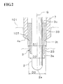
- a portion (a small-diameter portion) 23 of the cylindrical member 3 which projects from the front end 4a of the plug body 4 is smaller in outside diameter than a portion (a large-diameter portion) 33 which is fixedly disposed within the plug body 4 and is concentric with the portion 23; specifically, outside diameter D2 of the portion 23 is smaller than outside diameter D1 of the portion 33.
- An annular front-end-oriented end face 3t is formed in a diameter transition region where the outside diameter changes between outside diameters D2 and D1.
- the front-end-oriented end face 3t is tapered in the same manner as is the front end 4a of the cylindrical portion 7, whereby the two end faces 3t and 4a form a single taper surface.
- the annular front-end-oriented end face 3t which is formed in the diameter transition region of the metallic, cylindrical member 3 is aligned, in the direction of axis G of the ceramic heater 2, with the front end 4a of the plug body 4 in the form of a taper surface.
- the annular front-end-oriented end face 3t can be disposed within the plug body 4, that is the front-end-oriented end face 3t is preferably shifted toward the rear end from the front end of the plug body. More preferably, the annular front-end-oriented end face 3t can be disposed within the tapered front end 4a of the plug body 4 as shown in Fig. 5. It is because such a structure can prevent a pressure concentration at the front end of the front-end-oriented end face 3t.
- the large-diameter portion 33 which is located on the side toward the rear end with respect to the front-end-oriented end face 3t and has a relatively large diameter, has an outside diameter D1 of 6 mm; and the small-diameter portion 23, which is located on the side toward the front end with respect to the front-end-oriented end face 3t and has a relatively small diameter, has an outside diameter D2 of 5 mm.
- the difference between D1 and D2 is 1 mm.
- the cylindrical member 3 in the present embodiment is formed of SUS430 defined by JIS G 4308 (1981) and joined with the ceramic heater 2 in the following manner.
- the ceramic heater 2 is loosely fitted into the cylindrical member 3, and a molten brazing metal (not shown) is poured into the gap therebetween.
- Thermal expansion of the cylindrical member 3 induced by the poured, molten brazing metal and contraction of the cylindrical member 3 induced by cooling are utilized for hermetically fixing the ceramic heater 2 in the cylindrical member 3 through squeezing action of the cylindrical member 3.
- the body 4 is formed of a steel equivalent to S40C defined in JIS G 4051 (1979), such as STKM16 defined by JIS G 3445 (1983).
- the large-diameter portion 33, located on the side toward the rear end, of the cylindrical member 3 united with the ceramic heater 2 is press-fitted at a press fit tolerance of 10 ⁇ m (as measured diametrically) into the cylindrical portion 7 of the body 4 until the front-end-oriented end face 3t formed in the diameter transfer region thereof is aligned with the taper of the front end 4a of the body 4, to thereby be fixed on the inner circumferential surface of the cylindrical portion 7.
- the thus-configured glow plug 1 of the present embodiment is mounted onto a cylinder head 101 of a diesel engine via the thread portion 6 formed on the outer circumferential surface of the body 2.
- the cylinder head 101 has the glow plug mounting bore 104 formed therein in such a manner as to extend therethrough to the prechamber 103.
- the glow plug 1 is inserted, from its front end, into the mounting bore 104 and screw-engaged with the threaded portion 105 of the mounting bore 104 via the threaded portion 6 formed on the outer circumferential surface of the body 4 to thereby be mounted.
- the following structural feature is employed.
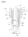
- the mounting bore 104 has the threaded portion 105, into which the threaded portion 6 of the body 4 can be screwed. As shown in Fig. 4, at a location located deeper than the threaded portion 105, the mounting bore 104 has a cylindrical bore 106, into which the cylindrical portion 7, located on the side toward the front end 4a, of the body 4 can be loosely fitted. At a deep location, the cylindrical bore 106 has a dead end portion 107, whose bore diameter is smaller than the thread diameter of the threaded portion 105 and which assumes the form of an annular tapered seat face.
- the dead end portion 107 is tapered in the same manner as are the body front end 4a and the front-end-oriented end face 3t of the cylindrical member 3, thereby allowing the front end 4a and the front-end-oriented end face 3t to abut the same.
- a cylindrical, small bore 108 is formed concentric with the cylindrical bore 106.
- the cylindrical, small bore 108 has diameter D3 which is smaller than the diameter of the cylindrical bore 106 and slightly larger than outside diameter D2 of the small-diameter portion 23 of the cylindrical member 3.
- Diameter D3 of the cylindrical, small bore 108 is set at about 5.8 mm, smaller than outside diameter D1 of the large-diameter portion 33 of the cylindrical member 3 and larger than outside diameter D2 of the small-diameter portion 23.
- the glow plug 1 is inserted, from its front end 2a, into the mounting bore 104.
- the threaded portion 6 formed on the outer circumferential surface of the body 4 is screwed into the threaded portion 105 of the mounting bore 104, whereby the glow plug 1 is mounted in the mounting bore 104.
- the front end 4a of the cylindrical portion 7 of the body 4 and the front-end-oriented end Face 3t of the cylindrical member 3 rests on and is pressed against the dead end portion 107 located at a deep location of the cylindrical bore 106.
- the glow plug 1 is mounted onto the cylinder head 101 while sealing against the cylinder head 101.
- the dead end portion 107 provided within the mounting bore 104 serves as movement prevention means for preventing movement of the metallic, cylindrical member 3 into the cylinder head 101.
- the front-end-oriented end face 3t of the cylindrical member 3 is disposed at the dead end portion 107 such that further movement toward the glow plug front end is prevented; i.e., entry into the prechamber 103 is prevented. Accordingly, the glow plug mounting structure can be such that, even when fixation of the cylindrical member 3 and the body 4 becomes loose, the cylindrical member 3 does not enter (drop into) the prechamber 103.
- the present invention can reliably prevent the worst case where the cylindrical member 3 drops into the prechamber 103 and thus can realize fixation through press fitting whose lower limit of tolerance is set low. Therefore, the cylindrical member to which the heater is fixedly attached can be fixedly attached to the body without employment of troublesome brazing, whereby the cost of a glow plug is reduced.
- the present invention is not limited to the above-described embodiment, but may be embodied as appropriate through modification of design without departing from the spirit or scope of the invention.
- the front end 4a of the body 4 may assume the form of a plane perpendicular to axis G
- the front-end-oriented end face 3t formed in the diameter transition region of the cylindrical member 3 may also assume the form of a plane perpendicular to axis G.
- the dead end portion 107 of a mounting bore formed in a cylinder head may also assume the form of a plane, so that the front end 4a of the body 4 and the front-end-oriented end face 3t of the metallic, cylindrical member 3 can be pressed against the dead end portion 107 while being aligned with each other.
- the second embodiment shown in Fig. 6 differs from the above-described embodiment only in the above-described structural feature. Therefore, portions similar to those in Figs. 1 to 4 are denoted by common reference numerals, and repeated description thereof is omitted. This also applies to embodiments to be described below.
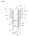
- the glow plug shown in Fig. 6 may be configured such that, as in the case of a third embodiment shown in Fig. 7, the dead end portion 107 of the mounting bore is tapered as described above in relation to the first embodiment.
- the front-end-oriented end face 3t of the cylindrical member 3 in a normal state, is not pressed against the dead end portion 107.
- the front-end-oriented end face 3t of the cylindrical member 3 moves to the dead end portion 107, further movement toward the glow plug front end is prevented, whereby entry into the interior of the cylinder head is prevented.
- the mounting structure may be such that, as in the case of a fourth embodiment shown in Fig. 8, the front-end-oriented end face 3t of the cylindrical member 3 is located ahead of the front end 4a of the body 4 toward the glow plug front end in the direction of axis G.
- the front end 4a of the body 4 is pressed against the dead end portion 107, whereas the front-end-oriented end face 3t of the cylindrical member 3 is located deeper than the dead end portion 107 and disposed within an intermediate bore 109, whose diameter D4 is greater than outside diameter D1 of the large-diameter portion 33 of the cylindrical member 3.
- Diameter D5 of a deep portion of the intermediate bore 109 is set smaller than outside diameter D1 of the large-diameter portion 33 of the cylindrical member 3.
- a rear-end-oriented end face 110 is formed at a deep location of the intermediate bore 109 and serves as movement prevention means for preventing the front-end-oriented end face 3t from moving deep.
- the front-end-oriented end face 3t of the cylindrical member 3 in a normal state, is not pressed against the rear-end-oriented end face 110.
- the front-end-oriented end face 3t of the cylindrical member 3 moves to the rear-end-oriented end face 110, further movement toward the glow plug front end is prevented.
- the structure for mounting a ceramic glow plug on a cylinder head of the present invention may be such that movement prevention means for preventing the front-end-oriented end face of a metallic, cylindrical member from moving deep into the mounting bore is provided in the mounting bore so as to prevent the metallic, cylindrical member from moving deep into the mounting bore and then into the interior of the cylinder head.
- the present invention can also be embodied such that a metallic, cylindrical member is fixedly disposed within a metallic, cylindrical plug body via a brazing metal.
- fixation may be effected in the following manner.
- a cylindrical member joined with a ceramic heater is loosely fitted into a cylindrical portion of a body.
- a heated, molten brazing metal e.g., silver brazing metal
- a heated, molten brazing metal is poured into the gap therebetween, followed by cooling for solidification.
- the glow plug of the present invention readily provides a glow plug mounting structure such that, even when loosening arises at a joint between a body and a cylindrical member after the glow plug is mounted onto a cylinder head, an assembly consisting of the cylindrical member and a ceramic heater is prevented from dropping off the body and entering an engine (prechamber).
- a mounting structure reliably prevents an assembly consisting of a cylindrical member and a heater from dropping off a body and entering an engine (prechamber) regardless of means for joining the body and the cylindrical member.
Landscapes
- Engineering & Computer Science (AREA)
- Chemical & Material Sciences (AREA)
- Combustion & Propulsion (AREA)
- Mechanical Engineering (AREA)
- General Engineering & Computer Science (AREA)
- Resistance Heating (AREA)
- Cylinder Crankcases Of Internal Combustion Engines (AREA)
- Combustion Methods Of Internal-Combustion Engines (AREA)
Abstract
Description
Claims (10)
- A ceramic glow plug (1) comprising a ceramic heater (2) fixedly disposed in a metallic, cylindrical member (3) such that a front end (2a) thereof projects from a front end (3a) of the metallic, cylindrical member (3), and wherein the resultant assembly consisting of the ceramic heater (2) and the metallic, cylindrical member (3) is fixedly disposed in a metallic, cylindrical plug body (4) such that the front end (3a) of the metallic, cylindrical member (3) projects from a front end (4a) of the metallic, cylindrical plug body (4),
characterized in that a portion (23) of the metallic, cylindrical member (3) which projects from the front end (4a) of the metallic, cylindrical plug body (4) and extends over a predetermined range from the front end (3a) of the metallic, cylindrical member (3) toward a rear end (3c) of the metallic, cylindrical member (3) is smaller in outside diameter than a portion (33) of the metallic, cylindrical member (3) which is fixedly disposed within the metallic, cylindrical plug body (4), and that a front-end-oriented end face (3t) is formed in a diameter transition region of the metallic, cylindrical member (3) where the outside diameter changes between those of the two portions (23, 33). - A ceramic glow plug according to claim 1, wherein the front-end-oriented end face (3t) formed in the diameter transition region of the metallic, cylindrical member (3) and the front end (4a) of the metallic, cylindrical plug body (4) are substantially aligned with each other.
- A ceramic glow plug according to claim 1 or 2, wherein the front-end-oriented end face (3t) formed in the diameter transition region of the metallic, cylindrical member (3) is disposed within the metallic, cylindrical plug body (4).
- A ceramic glow plug according to claim 1, 2 or 3, wherein the front-end-oriented end face (3t) formed in the diameter transition region of the metallic, cylindrical member (3) is disposed within a tapered front end (4a) of the metallic, cylindrical plug body (4).
- A ceramic glow plug according to any one of the preceding claims, wherein a difference in outside diameter between a small-diameter portion (23) of the metallic, cylindrical member (3) and a large-diameter portion (33) of the metallic, cylindrical member (3) is not less than 0.3 mm, the small-diameter portion (23) having a relatively smaller diameter (D2) and being located on a side toward the front end (3a) with respect to the front-end-oriented end face (3t), which is formed in the diameter transition region of the metallic, cylindrical member (3), and the large-diameter portion (33) having a relatively larger diameter (D1) and being located on a side toward the rear end (3c) with respect to front-end-oriented end face (3t).
- A ceramic glow plug according to any one of the preceding claims, wherein the metallic, cylindrical member (3) is press-fitted into the metallic, cylindrical plug body (4).
- A ceramic glow plug according to any one of claims 1 to 5, wherein the metallic, cylindrical member (3) is fixedly disposed in the metallic, cylindrical plug body (4) via a brazing metal.
- A structure for mounting a ceramic glow plug (1) on a cylinder head (101) wherein a glow plug is mounted onto a cylinder head (101) via a threaded portion (6) formed on an outer circumferential surface of the metallic, cylindrical plug body (4) in such a manner as to be screwed into a threaded portion (105) of a ceramic glow plug mounting bore (104) formed in the cylinder head (101) until the front end (4a) of the metallic, cylindrical plug body (4) is pressed against a dead end portion (107) located at a deep location of the mounting bore (104) and having a bore diameter (D3) smaller than a thread diameter of the threaded portion (105) of the mounting bore (104),
the structure for mounting a ceramic glow plug (1) on a cylinder head (101) being characterized by comprising a ceramic glow plug according any one of the preceding claims, and
further characterized in that movement prevention means (107, 110) is provided in the mounting bore (104) for preventing movement of the front-end-oriented end face (3t) deep into the mounting bore (104) so as to prevent the metallic, cylindrical member (3) from moving deep into the mounting bore (104) and into the interior of the cylinder head (101). - A structure for mounting a ceramic glow plug on a cylinder head (101) according to claim 8, wherein the movement prevention means (107) is implemented by rendering the bore diameter (D3) of the dead end portion (107) of the mounting bore (104) smaller than an outside diameter (D1) of a large-diameter portion (33) having a relatively larger diameter (D1) and being located on a side toward the rear end (3c) with respect to the front-end-oriented end face (3t).
- A structure for mounting a ceramic glow plug on a cylinder head (101) according to claim 8, wherein the movement prevention means (110) is implemented by rendering a diameter (D5) of the mounting bore (104) as measured at a location located deeper than the dead end portion (107) smaller than an outside diameter (D1) of a large-diameter portion (33) having a relatively larger diameter and being located on a side toward the rear end (3c) with respect to the front-end-oriented end face (3t).
Applications Claiming Priority (2)
| Application Number | Priority Date | Filing Date | Title |
|---|---|---|---|
| JP2001077151A JP4441136B2 (en) | 2001-03-16 | 2001-03-16 | Ceramic glow plug and its mounting structure to cylinder head |
| JP2001077151 | 2001-03-16 |
Publications (3)
| Publication Number | Publication Date |
|---|---|
| EP1241412A2 true EP1241412A2 (en) | 2002-09-18 |
| EP1241412A3 EP1241412A3 (en) | 2005-03-02 |
| EP1241412B1 EP1241412B1 (en) | 2008-01-23 |
Family
ID=18933951
Family Applications (1)
| Application Number | Title | Priority Date | Filing Date |
|---|---|---|---|
| EP02251858A Expired - Lifetime EP1241412B1 (en) | 2001-03-16 | 2002-03-15 | Ceramic glow plug and structure for mounting the same onto cylinder head |
Country Status (4)
| Country | Link |
|---|---|
| US (1) | US6831253B2 (en) |
| EP (1) | EP1241412B1 (en) |
| JP (1) | JP4441136B2 (en) |
| DE (1) | DE60224741T2 (en) |
Cited By (3)
| Publication number | Priority date | Publication date | Assignee | Title |
|---|---|---|---|---|
| FR2830924A1 (en) * | 2001-10-16 | 2003-04-18 | Denso Corp | Preheating plug for diesel engine, comprises cylindrical box fixed to cylinder head, cylindrical sleeve partly within the box and heating element supported by sleeve and made from a ceramic |
| EP1434005A3 (en) * | 2002-12-26 | 2006-08-30 | Ngk Spark Plug Co., Ltd. | Glow plug and glow-plug-mounting structure |
| CN102216689A (en) * | 2008-10-23 | 2011-10-12 | 费德罗-莫格尔点火公司 | Glow plug with improved seal, heater probe assembly therefor and method of construction thereof |
Families Citing this family (15)
| Publication number | Priority date | Publication date | Assignee | Title |
|---|---|---|---|---|
| US6727473B2 (en) * | 2001-03-09 | 2004-04-27 | Ngk Spark Plug Co., Ltd. | Ceramic heater device and method for manufacturing the device |
| JP4093175B2 (en) * | 2003-11-17 | 2008-06-04 | 株式会社デンソー | Glow plug |
| US7115836B2 (en) * | 2004-06-29 | 2006-10-03 | Ngk Spark Plug Co., Ltd. | Glow plug |
| ATE544034T1 (en) * | 2004-09-15 | 2012-02-15 | Beru Ag | PRESSURE MEASUREMENT GLOW PLUG FOR A DIESEL ENGINE |
| US20100078421A1 (en) * | 2008-10-01 | 2010-04-01 | Federal-Mogul Italy Sr1 | Glow plug adn heater assembly therefor with an improved connection between a central electrode and a heater probe of the heater assembly |
| CN102224381B (en) * | 2008-11-27 | 2013-10-16 | 博格华纳贝鲁系统有限责任公司 | Glow plug and method for producing the same |
| DE102009011415B4 (en) * | 2009-03-03 | 2013-09-26 | Beru Ag | Ceramic glow plug |
| JP5363653B2 (en) | 2011-02-25 | 2013-12-11 | 日本特殊陶業株式会社 | Glow plug with combustion pressure sensor |
| WO2012140892A1 (en) * | 2011-04-15 | 2012-10-18 | 日本特殊陶業株式会社 | Glow plug |
| EP2701459B1 (en) * | 2011-04-19 | 2018-03-28 | NGK Spark Plug Co., Ltd. | Ceramic heater and manufacturing method thereof |
| JP6251578B2 (en) * | 2014-01-20 | 2017-12-20 | 日本特殊陶業株式会社 | Glow plug |
| WO2017091761A1 (en) | 2015-11-25 | 2017-06-01 | Yeti Coolers, Llc | Insulating container having vacuum insulated panels and method |
| JP6848388B2 (en) * | 2016-11-22 | 2021-03-24 | 株式会社デンソー | Glow plug mounting structure with combustion pressure sensor and glow plug with combustion pressure sensor |
| USD821824S1 (en) | 2017-05-16 | 2018-07-03 | Yeti Coolers, Llc | Insulating device |
| CN116950796A (en) * | 2023-07-18 | 2023-10-27 | 上海夏雪科技有限公司 | Internal combustion engine |
Family Cites Families (14)
| Publication number | Priority date | Publication date | Assignee | Title |
|---|---|---|---|---|
| GB861842A (en) * | 1958-06-27 | 1961-03-01 | Bosch Gmbh Robert | Improvements in glow plugs for internal combustion engines |
| US4346679A (en) * | 1979-02-01 | 1982-08-31 | Lucas Industries Limited | Starting aids for internal combustion engines |
| JPS6030606Y2 (en) * | 1980-12-29 | 1985-09-13 | いすゞ自動車株式会社 | Ceramic glow plug |
| JPS58132177U (en) * | 1982-03-02 | 1983-09-06 | 日産自動車株式会社 | Diesel engine preheating device |
| JPS59231323A (en) * | 1983-06-13 | 1984-12-26 | Ngk Spark Plug Co Ltd | Ceramic glow plug |
| JPH025270Y2 (en) * | 1984-09-05 | 1990-02-08 | ||
| JPS6325416A (en) * | 1986-07-17 | 1988-02-02 | Ngk Spark Plug Co Ltd | Ceramic glow plug |
| US5084607A (en) * | 1989-07-28 | 1992-01-28 | Caterpillar Inc. | Interference connection between a heating element and body of a glow plug |
| JP2835209B2 (en) * | 1991-07-08 | 1998-12-14 | 京セラ株式会社 | Ceramic heater |
| JPH06288333A (en) * | 1993-03-31 | 1994-10-11 | Jidosha Kiki Co Ltd | Preheater for diesel engine |
| JPH07217881A (en) * | 1994-01-26 | 1995-08-18 | Ngk Spark Plug Co Ltd | Ceramic glow plug |
| US6285007B1 (en) * | 1999-08-18 | 2001-09-04 | Delphi Technologies, Inc. | Ion sensor glow plug assembly |
| US6248980B1 (en) * | 1999-08-19 | 2001-06-19 | Delphi Technologies, Inc. | Ion sensor glow plug assembly |
| US6512204B1 (en) * | 2000-03-14 | 2003-01-28 | Delphi Technologies, Inc. | Ion sensor glow plug assembly |
-
2001
- 2001-03-16 JP JP2001077151A patent/JP4441136B2/en not_active Expired - Fee Related
-
2002
- 2002-03-15 DE DE60224741T patent/DE60224741T2/en not_active Expired - Lifetime
- 2002-03-15 US US10/097,594 patent/US6831253B2/en not_active Expired - Fee Related
- 2002-03-15 EP EP02251858A patent/EP1241412B1/en not_active Expired - Lifetime
Cited By (5)
| Publication number | Priority date | Publication date | Assignee | Title |
|---|---|---|---|---|
| FR2830924A1 (en) * | 2001-10-16 | 2003-04-18 | Denso Corp | Preheating plug for diesel engine, comprises cylindrical box fixed to cylinder head, cylindrical sleeve partly within the box and heating element supported by sleeve and made from a ceramic |
| EP1434005A3 (en) * | 2002-12-26 | 2006-08-30 | Ngk Spark Plug Co., Ltd. | Glow plug and glow-plug-mounting structure |
| CN102216689A (en) * | 2008-10-23 | 2011-10-12 | 费德罗-莫格尔点火公司 | Glow plug with improved seal, heater probe assembly therefor and method of construction thereof |
| EP2338001A4 (en) * | 2008-10-23 | 2012-07-18 | Federal Mogul Ignition Co | Glow plug with improved seal, heater probe assembly therefor and method of construction thereof |
| US8410403B2 (en) | 2008-10-23 | 2013-04-02 | Federal Mogul Ignition Company | Glow plug with improved seal, heater probe assembly therefor and method of construction thereof |
Also Published As
| Publication number | Publication date |
|---|---|
| US20020130121A1 (en) | 2002-09-19 |
| EP1241412B1 (en) | 2008-01-23 |
| DE60224741T2 (en) | 2009-01-22 |
| DE60224741D1 (en) | 2008-03-13 |
| US6831253B2 (en) | 2004-12-14 |
| JP2002276942A (en) | 2002-09-25 |
| EP1241412A3 (en) | 2005-03-02 |
| JP4441136B2 (en) | 2010-03-31 |
Similar Documents
| Publication | Publication Date | Title |
|---|---|---|
| EP1241412B1 (en) | Ceramic glow plug and structure for mounting the same onto cylinder head | |
| EP1434005B1 (en) | Glow plug and glow-plug-mounting structure | |
| US8003917B2 (en) | Seal for a glow plug | |
| KR101674976B1 (en) | Ignitor for air/fuel mixture and engine therewith and method of assembly thereof into a cylinder head | |
| US6286995B1 (en) | Temperature sensor | |
| US9964306B2 (en) | Glow plug | |
| CN110573724B (en) | Spark plug sleeve | |
| EP1707883B1 (en) | Ceramic heater-type glow plug | |
| US6155236A (en) | Fuel injection nozzle injecting onto the combustion space of an internal combustion engine | |
| JP5327270B2 (en) | Ceramic heater | |
| JP2000356343A (en) | Ceramic heater type glow plug | |
| JP2005207721A (en) | Glow plug | |
| EP2679901B1 (en) | Glow plug with combustion pressure sensor | |
| JP4632565B2 (en) | Ceramic heater device and manufacturing method thereof | |
| EP1457736A1 (en) | Glow plug for diesel engine and method of manufacturing the glow plug | |
| JP2002303424A (en) | Glow plug for diesel engine | |
| US20090050480A1 (en) | Exhaust gas sensor | |
| JPH045896Y2 (en) | ||
| US20190063390A1 (en) | Fuel injector | |
| JPH08609Y2 (en) | Ceramic glow plug | |
| JP3870859B2 (en) | Glow plug | |
| EP1308672B1 (en) | Glow plug for diesel engine and method of manufacturing same | |
| JPH07217881A (en) | Ceramic glow plug | |
| JP4921039B2 (en) | Spark plug | |
| JP2010032211A (en) | Ceramic glow plug and its mounting structure to cylinder head |
Legal Events
| Date | Code | Title | Description |
|---|---|---|---|
| PUAI | Public reference made under article 153(3) epc to a published international application that has entered the european phase |
Free format text: ORIGINAL CODE: 0009012 |
|
| AK | Designated contracting states |
Kind code of ref document: A2 Designated state(s): AT BE CH CY DE DK ES FI FR GB GR IE IT LI LU MC NL PT SE TR |
|
| AX | Request for extension of the european patent |
Free format text: AL;LT;LV;MK;RO;SI |
|
| PUAL | Search report despatched |
Free format text: ORIGINAL CODE: 0009013 |
|
| AK | Designated contracting states |
Kind code of ref document: A3 Designated state(s): AT BE CH CY DE DK ES FI FR GB GR IE IT LI LU MC NL PT SE TR |
|
| AX | Request for extension of the european patent |
Extension state: AL LT LV MK RO SI |
|
| 17P | Request for examination filed |
Effective date: 20050712 |
|
| AKX | Designation fees paid |
Designated state(s): DE FR GB IT |
|
| 17Q | First examination report despatched |
Effective date: 20061222 |
|
| GRAP | Despatch of communication of intention to grant a patent |
Free format text: ORIGINAL CODE: EPIDOSNIGR1 |
|
| GRAS | Grant fee paid |
Free format text: ORIGINAL CODE: EPIDOSNIGR3 |
|
| GRAA | (expected) grant |
Free format text: ORIGINAL CODE: 0009210 |
|
| AK | Designated contracting states |
Kind code of ref document: B1 Designated state(s): DE FR GB IT |
|
| REG | Reference to a national code |
Ref country code: GB Ref legal event code: FG4D |
|
| REF | Corresponds to: |
Ref document number: 60224741 Country of ref document: DE Date of ref document: 20080313 Kind code of ref document: P |
|
| EN | Fr: translation not filed | ||
| PLBE | No opposition filed within time limit |
Free format text: ORIGINAL CODE: 0009261 |
|
| STAA | Information on the status of an ep patent application or granted ep patent |
Free format text: STATUS: NO OPPOSITION FILED WITHIN TIME LIMIT |
|
| GBPC | Gb: european patent ceased through non-payment of renewal fee |
Effective date: 20080423 |
|
| 26N | No opposition filed |
Effective date: 20081024 |
|
| PG25 | Lapsed in a contracting state [announced via postgrant information from national office to epo] |
Ref country code: FR Free format text: LAPSE BECAUSE OF FAILURE TO SUBMIT A TRANSLATION OF THE DESCRIPTION OR TO PAY THE FEE WITHIN THE PRESCRIBED TIME-LIMIT Effective date: 20081114 |
|
| PG25 | Lapsed in a contracting state [announced via postgrant information from national office to epo] |
Ref country code: GB Free format text: LAPSE BECAUSE OF NON-PAYMENT OF DUE FEES Effective date: 20080423 |
|
| PG25 | Lapsed in a contracting state [announced via postgrant information from national office to epo] |
Ref country code: IT Free format text: LAPSE BECAUSE OF FAILURE TO SUBMIT A TRANSLATION OF THE DESCRIPTION OR TO PAY THE FEE WITHIN THE PRESCRIBED TIME-LIMIT Effective date: 20080123 |
|
| REG | Reference to a national code |
Ref country code: DE Ref legal event code: R082 Ref document number: 60224741 Country of ref document: DE Representative=s name: KLUNKER IP PATENTANWAELTE PARTG MBB, DE |
|
| PGFP | Annual fee paid to national office [announced via postgrant information from national office to epo] |
Ref country code: DE Payment date: 20180227 Year of fee payment: 17 |
|
| REG | Reference to a national code |
Ref country code: DE Ref legal event code: R119 Ref document number: 60224741 Country of ref document: DE |
|
| PG25 | Lapsed in a contracting state [announced via postgrant information from national office to epo] |
Ref country code: DE Free format text: LAPSE BECAUSE OF NON-PAYMENT OF DUE FEES Effective date: 20191001 |