EP1241029A2 - Method and device for determining the driving status of a vehicle in the case of failure of or signal errors from a speed sensor - Google Patents
Method and device for determining the driving status of a vehicle in the case of failure of or signal errors from a speed sensor Download PDFInfo
- Publication number
- EP1241029A2 EP1241029A2 EP02001218A EP02001218A EP1241029A2 EP 1241029 A2 EP1241029 A2 EP 1241029A2 EP 02001218 A EP02001218 A EP 02001218A EP 02001218 A EP02001218 A EP 02001218A EP 1241029 A2 EP1241029 A2 EP 1241029A2
- Authority
- EP
- European Patent Office
- Prior art keywords
- vehicle
- values
- frequency
- travel
- determining
- Prior art date
- Legal status (The legal status is an assumption and is not a legal conclusion. Google has not performed a legal analysis and makes no representation as to the accuracy of the status listed.)
- Granted
Links
Images


Classifications
-
- B—PERFORMING OPERATIONS; TRANSPORTING
- B60—VEHICLES IN GENERAL
- B60G—VEHICLE SUSPENSION ARRANGEMENTS
- B60G17/00—Resilient suspensions having means for adjusting the spring or vibration-damper characteristics, for regulating the distance between a supporting surface and a sprung part of vehicle or for locking suspension during use to meet varying vehicular or surface conditions, e.g. due to speed or load
- B60G17/015—Resilient suspensions having means for adjusting the spring or vibration-damper characteristics, for regulating the distance between a supporting surface and a sprung part of vehicle or for locking suspension during use to meet varying vehicular or surface conditions, e.g. due to speed or load the regulating means comprising electric or electronic elements
- B60G17/0195—Resilient suspensions having means for adjusting the spring or vibration-damper characteristics, for regulating the distance between a supporting surface and a sprung part of vehicle or for locking suspension during use to meet varying vehicular or surface conditions, e.g. due to speed or load the regulating means comprising electric or electronic elements characterised by the regulation being combined with other vehicle control systems
-
- B—PERFORMING OPERATIONS; TRANSPORTING
- B60—VEHICLES IN GENERAL
- B60G—VEHICLE SUSPENSION ARRANGEMENTS
- B60G17/00—Resilient suspensions having means for adjusting the spring or vibration-damper characteristics, for regulating the distance between a supporting surface and a sprung part of vehicle or for locking suspension during use to meet varying vehicular or surface conditions, e.g. due to speed or load
- B60G17/015—Resilient suspensions having means for adjusting the spring or vibration-damper characteristics, for regulating the distance between a supporting surface and a sprung part of vehicle or for locking suspension during use to meet varying vehicular or surface conditions, e.g. due to speed or load the regulating means comprising electric or electronic elements
- B60G17/018—Resilient suspensions having means for adjusting the spring or vibration-damper characteristics, for regulating the distance between a supporting surface and a sprung part of vehicle or for locking suspension during use to meet varying vehicular or surface conditions, e.g. due to speed or load the regulating means comprising electric or electronic elements characterised by the use of a specific signal treatment or control method
- B60G17/0185—Resilient suspensions having means for adjusting the spring or vibration-damper characteristics, for regulating the distance between a supporting surface and a sprung part of vehicle or for locking suspension during use to meet varying vehicular or surface conditions, e.g. due to speed or load the regulating means comprising electric or electronic elements characterised by the use of a specific signal treatment or control method for failure detection
-
- B—PERFORMING OPERATIONS; TRANSPORTING
- B60—VEHICLES IN GENERAL
- B60G—VEHICLE SUSPENSION ARRANGEMENTS
- B60G17/00—Resilient suspensions having means for adjusting the spring or vibration-damper characteristics, for regulating the distance between a supporting surface and a sprung part of vehicle or for locking suspension during use to meet varying vehicular or surface conditions, e.g. due to speed or load
- B60G17/015—Resilient suspensions having means for adjusting the spring or vibration-damper characteristics, for regulating the distance between a supporting surface and a sprung part of vehicle or for locking suspension during use to meet varying vehicular or surface conditions, e.g. due to speed or load the regulating means comprising electric or electronic elements
- B60G17/019—Resilient suspensions having means for adjusting the spring or vibration-damper characteristics, for regulating the distance between a supporting surface and a sprung part of vehicle or for locking suspension during use to meet varying vehicular or surface conditions, e.g. due to speed or load the regulating means comprising electric or electronic elements characterised by the type of sensor or the arrangement thereof
-
- B—PERFORMING OPERATIONS; TRANSPORTING
- B60—VEHICLES IN GENERAL
- B60W—CONJOINT CONTROL OF VEHICLE SUB-UNITS OF DIFFERENT TYPE OR DIFFERENT FUNCTION; CONTROL SYSTEMS SPECIALLY ADAPTED FOR HYBRID VEHICLES; ROAD VEHICLE DRIVE CONTROL SYSTEMS FOR PURPOSES NOT RELATED TO THE CONTROL OF A PARTICULAR SUB-UNIT
- B60W40/00—Estimation or calculation of non-directly measurable driving parameters for road vehicle drive control systems not related to the control of a particular sub unit, e.g. by using mathematical models
- B60W40/10—Estimation or calculation of non-directly measurable driving parameters for road vehicle drive control systems not related to the control of a particular sub unit, e.g. by using mathematical models related to vehicle motion
-
- B—PERFORMING OPERATIONS; TRANSPORTING
- B60—VEHICLES IN GENERAL
- B60W—CONJOINT CONTROL OF VEHICLE SUB-UNITS OF DIFFERENT TYPE OR DIFFERENT FUNCTION; CONTROL SYSTEMS SPECIALLY ADAPTED FOR HYBRID VEHICLES; ROAD VEHICLE DRIVE CONTROL SYSTEMS FOR PURPOSES NOT RELATED TO THE CONTROL OF A PARTICULAR SUB-UNIT
- B60W50/00—Details of control systems for road vehicle drive control not related to the control of a particular sub-unit, e.g. process diagnostic or vehicle driver interfaces
- B60W50/02—Ensuring safety in case of control system failures, e.g. by diagnosing, circumventing or fixing failures
- B60W50/0205—Diagnosing or detecting failures; Failure detection models
-
- B—PERFORMING OPERATIONS; TRANSPORTING
- B60—VEHICLES IN GENERAL
- B60G—VEHICLE SUSPENSION ARRANGEMENTS
- B60G2400/00—Indexing codes relating to detected, measured or calculated conditions or factors
- B60G2400/20—Speed
- B60G2400/204—Vehicle speed
-
- B—PERFORMING OPERATIONS; TRANSPORTING
- B60—VEHICLES IN GENERAL
- B60G—VEHICLE SUSPENSION ARRANGEMENTS
- B60G2400/00—Indexing codes relating to detected, measured or calculated conditions or factors
- B60G2400/20—Speed
- B60G2400/206—Body oscillation speed; Body vibration frequency
-
- B—PERFORMING OPERATIONS; TRANSPORTING
- B60—VEHICLES IN GENERAL
- B60G—VEHICLE SUSPENSION ARRANGEMENTS
- B60G2400/00—Indexing codes relating to detected, measured or calculated conditions or factors
- B60G2400/25—Stroke; Height; Displacement
- B60G2400/252—Stroke; Height; Displacement vertical
-
- B—PERFORMING OPERATIONS; TRANSPORTING
- B60—VEHICLES IN GENERAL
- B60G—VEHICLE SUSPENSION ARRANGEMENTS
- B60G2400/00—Indexing codes relating to detected, measured or calculated conditions or factors
- B60G2400/90—Other conditions or factors
- B60G2400/91—Frequency
-
- B—PERFORMING OPERATIONS; TRANSPORTING
- B60—VEHICLES IN GENERAL
- B60G—VEHICLE SUSPENSION ARRANGEMENTS
- B60G2600/00—Indexing codes relating to particular elements, systems or processes used on suspension systems or suspension control systems
- B60G2600/08—Failure or malfunction detecting means
-
- B—PERFORMING OPERATIONS; TRANSPORTING
- B60—VEHICLES IN GENERAL
- B60W—CONJOINT CONTROL OF VEHICLE SUB-UNITS OF DIFFERENT TYPE OR DIFFERENT FUNCTION; CONTROL SYSTEMS SPECIALLY ADAPTED FOR HYBRID VEHICLES; ROAD VEHICLE DRIVE CONTROL SYSTEMS FOR PURPOSES NOT RELATED TO THE CONTROL OF A PARTICULAR SUB-UNIT
- B60W10/00—Conjoint control of vehicle sub-units of different type or different function
- B60W10/22—Conjoint control of vehicle sub-units of different type or different function including control of suspension systems
-
- B—PERFORMING OPERATIONS; TRANSPORTING
- B60—VEHICLES IN GENERAL
- B60W—CONJOINT CONTROL OF VEHICLE SUB-UNITS OF DIFFERENT TYPE OR DIFFERENT FUNCTION; CONTROL SYSTEMS SPECIALLY ADAPTED FOR HYBRID VEHICLES; ROAD VEHICLE DRIVE CONTROL SYSTEMS FOR PURPOSES NOT RELATED TO THE CONTROL OF A PARTICULAR SUB-UNIT
- B60W50/00—Details of control systems for road vehicle drive control not related to the control of a particular sub-unit, e.g. process diagnostic or vehicle driver interfaces
- B60W50/02—Ensuring safety in case of control system failures, e.g. by diagnosing, circumventing or fixing failures
- B60W50/0205—Diagnosing or detecting failures; Failure detection models
- B60W2050/0215—Sensor drifts or sensor failures
-
- B—PERFORMING OPERATIONS; TRANSPORTING
- B60—VEHICLES IN GENERAL
- B60W—CONJOINT CONTROL OF VEHICLE SUB-UNITS OF DIFFERENT TYPE OR DIFFERENT FUNCTION; CONTROL SYSTEMS SPECIALLY ADAPTED FOR HYBRID VEHICLES; ROAD VEHICLE DRIVE CONTROL SYSTEMS FOR PURPOSES NOT RELATED TO THE CONTROL OF A PARTICULAR SUB-UNIT
- B60W50/00—Details of control systems for road vehicle drive control not related to the control of a particular sub-unit, e.g. process diagnostic or vehicle driver interfaces
- B60W50/02—Ensuring safety in case of control system failures, e.g. by diagnosing, circumventing or fixing failures
- B60W50/029—Adapting to failures or work around with other constraints, e.g. circumvention by avoiding use of failed parts
- B60W2050/0292—Fail-safe or redundant systems, e.g. limp-home or backup systems
-
- B—PERFORMING OPERATIONS; TRANSPORTING
- B60—VEHICLES IN GENERAL
- B60W—CONJOINT CONTROL OF VEHICLE SUB-UNITS OF DIFFERENT TYPE OR DIFFERENT FUNCTION; CONTROL SYSTEMS SPECIALLY ADAPTED FOR HYBRID VEHICLES; ROAD VEHICLE DRIVE CONTROL SYSTEMS FOR PURPOSES NOT RELATED TO THE CONTROL OF A PARTICULAR SUB-UNIT
- B60W2520/00—Input parameters relating to overall vehicle dynamics
- B60W2520/10—Longitudinal speed
Definitions
- the invention relates to a method for determining the Driving state of a vehicle in the event of failure or absence of a Speed sensor and a device for performing of the procedure.
- the object of the present invention is to specify a procedure and a facility with which even if a vehicle speed sensor fails or is missing a distinction is made between driving and standstill can, for example, also in such a case, a control intervention in a level control or shock absorber control to be able to carry out or control and an existing one Check vehicle speed sensor for plausibility to be able to.
- a facility for performing the method is in Claim 4 specified.
- the invention enables plausibility monitoring of vehicle speed sensors possible. Even in the event of failure or lack of a vehicle speed sensor can be caused by distinguished the invention between driving and standstill become.
- the invention enables the determination of Vibration frequency of the spring travel or the spring travel.
- Functionalities of level control or shock absorber control those when driving, stationary or certain Oscillation frequencies of the suspension travel or the suspension travel blocked or should be activated can with the help of the invention be blocked or activated.
- the invention Method and the device according to the invention works regardless of the static deflection of the travel or the travel.
- the invention is applicable to vehicles with at least a travel sensor on at least one wheel or at least one axis.
- the invention is also applicable for vehicles that have at least one suspension travel sensor additionally an electronically controlled level control or electronic shock absorber control or regulation have and / or additionally via an electronic Speed sensor.
- the invention enables Equip vehicles with additional functionalities, which is otherwise only available for vehicles with a vehicle speed sensor are conceivable.
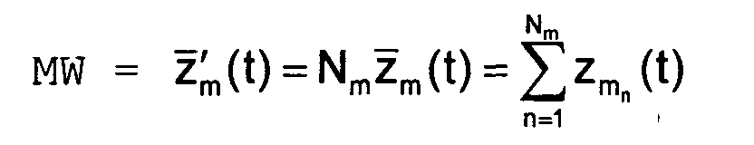
- the sum MW can be entered in block 2 the recorded current travel values z m n (t) are formed. Provided that the travel values z m n (t) are in integer format, this procedure allows operations in integer arithmetic and avoids floating point operations.
- this frequency f m becomes critical with a predeterminable critical value f m assigned to the vehicle standstill, or the number N E m the extremes determined during the observation period T B with a predeterminable, critical value N E assigned to the vehicle standstill m , compared.
- the determination of the frequency f m of the vertical relative movement or the determination of the number N E m Ascertained extremes of the vertical relative movement of the vehicle body and the axis are carried out continuously, as described, with the observation period T B.
- a device 14 is provided for determining the amounts of change of the mean values or of the sums MW of the captured spring travel of the vertical relative movement, i.e.
- a comparator 16 with a definable critical value crit compared, which controls the counter 8, such that a local extremum is only counted when the amount of change in the mean values or the sum MW of the spring travel recorded for the vertical relative movement exceeds the critical value d crit , ie when the sum MW is considered
- the method described above can be adapted to the vibration properties of a vehicle and the resolution of the travel sensors.
- the quantity MW corresponds to the integer sum z ' m (t) of the recorded travel values z m n (t) .
Landscapes
- Engineering & Computer Science (AREA)
- Mechanical Engineering (AREA)
- Automation & Control Theory (AREA)
- Transportation (AREA)
- Physics & Mathematics (AREA)
- Mathematical Physics (AREA)
- Human Computer Interaction (AREA)
- Vehicle Body Suspensions (AREA)
Abstract
Description
Die Erfindung betrifft ein Verfahren zur Ermittlung des Fahrzustandes eines Fahrzeugs bei Ausfall oder Fehlen eines Geschwindigkeitssensors sowie eine Einrichtung zur Durchführung des Verfahrens.The invention relates to a method for determining the Driving state of a vehicle in the event of failure or absence of a Speed sensor and a device for performing of the procedure.
Bei Ausfall oder Fehlen eines Geschwindigkeitssensors kann nicht mehr zwischen Fahrt und Stillstand eines Fahrzeugs unterschieden werden, was bspw. für die Funktionsfähigkeit von Niveau- und Stoßdämpferregelungen nachteilig ist.In the event of failure or lack of a speed sensor can no longer between driving and standstill of a vehicle a distinction is made, for example, for functionality of level and shock absorber regulations disadvantageous is.
Aus der DE 196 48 176 ist eine Niveauregeleinrichtung zur Regelung des Abstandes zwischen einem Fahrzeugchassis und einem Fahrzeugaufbau eines luftgefederten Fahrzeugs mit Steuerung der Schwingungsdämpfer bekannt. Für diese Steuerung wird ein Stellsignal verwendet, das einem nach bekannter Weise ermittelten Dämpfungsbedarf für die Bewegung des Fahrzeugaufbaus entspricht. Dieser Dämpfungsbedarf wird durch eine den Straßenzustand beschreibende Schlechtweg-Kenngröße modifiziert, um die Fahrsicherheit und den Komfort zu verbessern. Die Berechnung der Schlechtweg-Kenngröße erfolgt unter Verwendung der Beschleunigung des Federweges, die durch zweifache Differentiation des gemessenen Federweges erzeugt wird. Die zu dämpfenden Aufbaubewegungen sind durch die Ermittlung von Walkwinkel und Walkfrequenz sowie von Nickwinkel und Nickfrequenz des Fahrzeugaufbaus festgelegt. Diese bekannte Regeleinrichtung ist für die Unterscheidung zwischen Fahrt und Stillstand eines Fahrzeugs sowie für die Ermittlung der Frequenz des zeitlichen Verlaufs der Federwege und damit für
- eine Plausibilitätsüberwachung eines Fahrgeschwindigkeitssensors,
- das Sperren oder Aktivieren beliebiger Funktionen einer elektronisch gesteuerten Niveauregulierung, je nach ermitteltem Fahrzustand (Stillstand oder Fahrt) oder je nach ermittelter Frequenz des zeitlichen Verlaufs der Federwege, und
- das Sperren oder Aktivieren beliebiger Funktionen einer elektronischen Stoßdämpfersteuerung oder -regelung, je nach ermitteltem Fahrzustand (Stillstand oder Fahrt) oder je nach ermittelter Frequenz des zeitlichen Verlaufs der Federwege
- plausibility monitoring of a vehicle speed sensor,
- blocking or activating any functions of an electronically controlled level control, depending on the determined driving state (standstill or driving) or depending on the frequency determined for the time course of the spring travel, and
- the blocking or activation of any functions of an electronic shock absorber control or regulation, depending on the determined driving condition (standstill or driving) or depending on the frequency determined in the course of the spring travel over time
Die Aufgabe der vorliegenden Erfindung besteht darin, ein Verfahren und eine Einrichtung anzugeben, mit denen auch bei Ausfall oder Fehlen eines Fahrgeschwindigkeitssensors zwischen Fahrt und Stillstand unterschieden werden kann, um bspw. auch in einem derartigen Fall einen Regeleingriff in eine Niveauregulierung oder Stoßdämpfersteuerung oder -regelung durchführen zu können und einen vorhandenen Fahrgeschwindigkeitssensor auf Plausibilität prüfen zu können. The object of the present invention is to specify a procedure and a facility with which even if a vehicle speed sensor fails or is missing a distinction is made between driving and standstill can, for example, also in such a case, a control intervention in a level control or shock absorber control to be able to carry out or control and an existing one Check vehicle speed sensor for plausibility to be able to.
Diese Aufgabe wird durch die Erfindung gemäß Anspruch 1
gelöst.This object is achieved by the invention according to
Eine Einrichtung zur Durchführung des Verfahrens ist im Anspruch 4 angegeben.A facility for performing the method is in Claim 4 specified.
Vorteilhafte und zweckmäßige Weiterbildungen sowie Anwendungen der Erfindung sind in den weiteren Ansprüchen angegeben.Advantageous and practical training and applications the invention are specified in the further claims.
Durch die Erfindung ist eine Plausibilitätsüberwachung von Fahrgeschwindigkeitssensoren möglich. Auch bei Ausfall oder Fehlen eines Fahrgeschwindigkeitssensors kann durch die Erfindung zwischen Fahrt und Stillstand unterschieden werden. Die Erfindung ermöglicht die Feststellung der Schwingungsfrequenz des Federweges bzw. der Federwege. Funktionalitäten von Niveauregulierungen oder Stoßdämpferregelungen, die bei Fahrt, Stillstand oder bestimmten Schwingungsfrequenzen des Federweges oder der Federwege gesperrt bzw. aktiviert sein sollen, können mit Hilfe der Erfindung gesperrt bzw. aktiviert werden. Das erfindungsgemäße Verfahren bzw. die erfindungsgemäße Einrichtung funktioniert unabhängig von der statischen Auslenkung des Federweges bzw. der Federwege.The invention enables plausibility monitoring of vehicle speed sensors possible. Even in the event of failure or lack of a vehicle speed sensor can be caused by distinguished the invention between driving and standstill become. The invention enables the determination of Vibration frequency of the spring travel or the spring travel. Functionalities of level control or shock absorber control, those when driving, stationary or certain Oscillation frequencies of the suspension travel or the suspension travel blocked or should be activated can with the help of the invention be blocked or activated. The invention Method and the device according to the invention works regardless of the static deflection of the travel or the travel.
Die Erfindung ist anwendbar bei Fahrzeugen mit mindestens einem Federwegsensor an mindestens einem Rad oder mindestens einer Achse. Ferner ist die Erfindung anwendbar bei Fahrzeugen, die außer mindestens einem Federwegsensor zusätzlich eine elektronisch gesteuerte Niveauregulierung oder eine elektronische Stoßdämpfersteuerung oder -regelung aufweisen und/oder die zusätzlich über einen elektronischen Fahrgeschwindigkeitssensor verfügen. Die Erfindung ermöglicht, Fahrzeuge mit zusätzlichen Funktionalitäten auszustatten, die sonst nur bei Fahrzeugen mit Fahrgeschwindigkeitssensor denkbar sind.The invention is applicable to vehicles with at least a travel sensor on at least one wheel or at least one axis. The invention is also applicable for vehicles that have at least one suspension travel sensor additionally an electronically controlled level control or electronic shock absorber control or regulation have and / or additionally via an electronic Speed sensor. The invention enables Equip vehicles with additional functionalities, which is otherwise only available for vehicles with a vehicle speed sensor are conceivable.
Die Erfindung soll nachfolgend anhand der beigefügten Zeichnung näher erläutert werden.The invention will now be described with reference to the accompanying Drawing will be explained in more detail.
Es zeigt
- Fig. 1
- ein Blockschaltbild einer erfindungsgemäßen Einrichtung zur Durchführung des erfindungsgemäßen Verfahrens und
- Fig. 2
- ein Diagramm zur Erläuterung der Bestimmung lokaler Extrema der Relativbewegung zwischen Fahrzeugaufbau und Fahrzeugachse mit zwei Federwegsensoren.
- Fig. 1
- a block diagram of an inventive device for performing the inventive method and
- Fig. 2
- a diagram for explaining the determination of local extremes of the relative movement between the vehicle body and the vehicle axle with two travel sensors.
Um festzustellen, ob sich ein Fahrzeug in Fahrt befindet,
wird zunächst der zeitliche Verlauf der Federwege des
Fahrzeuges mit mindestens der doppelten Radeigenfrequenz
mittels Federwegsensoren abgetastet. Zwecks Elimination der
Rollbewegungen des Fahrzeugaufbaues wird in einem ersten
Block 2 für jede Fahrzeugachse m zu jedem Abtastzeitpunkt t
mit
- k:
- Fortschrittszahl der Abtastung,
- T:
- Abtastperiode,

- m:
- Index der Achse und
- Nm:
- Anzahl der Federwegsensoren an der Achse m,
- k:
- Progress number of the scan,
- T:
- sampling
- m:
- Index of the axis and
- N m :
- Number of travel sensors on the axis m,
Anstelle des Mittelwertes kann im Block 2 die Summe MW
mit
Innerhalb einer festlegbaren Beobachtungsperiode TB
werden die lokalen Extrema des zeitlichen Verlaufes des
Mittelwertes
Liegt die derart ermittelte Frequenz fm oberhalb des
kritischen Wertes fm,krit bzw. liegt die Anzahl NE
Die Bestimmung der Frequenz fm der vertikalen Relativbewegung
bzw. die Ermittlung der Anzahl NE
Bei der Erkennung lokaler Extrema muß allerdings ein
Quantisierungsrauschen im Mittelwert 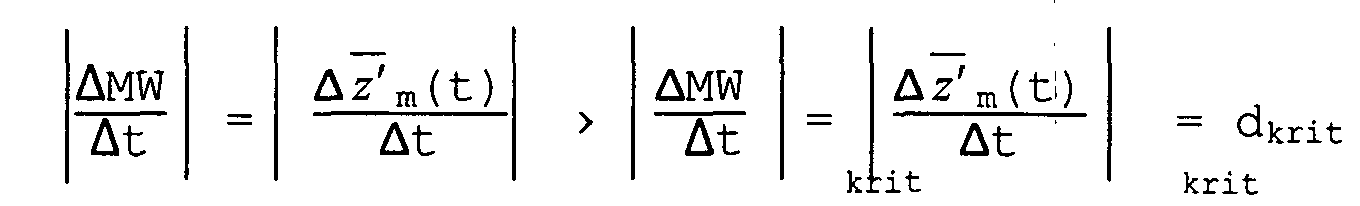
Durch Einstellung der Werte fm,krit bzw. NE
Die Fig. 2 zeigt die Anwendung des oben beschriebenen
Verfahrens zur Bestimmung lokaler Extrema der Relativbewegung
zwischen Fahrzeugaufbau und der Achse am Beispiel einer
Fahrzeugachse mit zwei Federwegsensoren und einem angenommenen
Wert dkrit = 2. In dieser Fig. 2 entspricht die
Größe MW der ganzzahligen Summe
Wenn der Betrag der Änderung des mitgeführten Mittelwertes MW' die Schwelle dkrit überschreitet, so wird die Zähleinrichtung für die Anzahl innerhalb der laufenden Beobachtungsperiode TB ermittelter lokaler Extrema inkrementiert.If the amount of change of the entrained average MW 'exceeds the threshold d crit, so the counting of the number within the current observation period T B is incremented determined local extrema.
Claims (9)
Applications Claiming Priority (2)
| Application Number | Priority Date | Filing Date | Title |
|---|---|---|---|
| DE10112159 | 2001-03-14 | ||
| DE10112159A DE10112159A1 (en) | 2001-03-14 | 2001-03-14 | Method and device for determining the driving condition of vehicles in the event of failure or lack of a speed sensor |
Publications (3)
| Publication Number | Publication Date |
|---|---|
| EP1241029A2 true EP1241029A2 (en) | 2002-09-18 |
| EP1241029A3 EP1241029A3 (en) | 2007-03-28 |
| EP1241029B1 EP1241029B1 (en) | 2009-12-09 |
Family
ID=7677364
Family Applications (1)
| Application Number | Title | Priority Date | Filing Date |
|---|---|---|---|
| EP02001218A Expired - Lifetime EP1241029B1 (en) | 2001-03-14 | 2002-01-17 | Method and device for determining the driving status of a vehicle in the case of failure of or signal errors from a speed sensor |
Country Status (3)
| Country | Link |
|---|---|
| US (1) | US6522961B2 (en) |
| EP (1) | EP1241029B1 (en) |
| DE (2) | DE10112159A1 (en) |
Families Citing this family (5)
| Publication number | Priority date | Publication date | Assignee | Title |
|---|---|---|---|---|
| WO2011080798A1 (en) * | 2009-12-28 | 2011-07-07 | トヨタ自動車株式会社 | Vehicle control device |
| WO2011121637A1 (en) * | 2010-03-29 | 2011-10-06 | トヨタ自動車株式会社 | Vehicle controller |
| EP2674341B1 (en) | 2011-02-10 | 2016-02-10 | Toyota Jidosha Kabushiki Kaisha | Hybrid vehicle and method for controlling hybrid vehicle |
| DE102019100984A1 (en) * | 2019-01-16 | 2020-07-16 | Dr. Ing. H.C. F. Porsche Aktiengesellschaft | Method for recognizing a kinematic state of a vehicle from level information |
| DE102019100976A1 (en) * | 2019-01-16 | 2020-07-16 | Dr. Ing. H.C. F. Porsche Aktiengesellschaft | METHOD FOR DETECTING A MOVEMENT STATE OF A VEHICLE FROM LEVEL INFORMATION |
Citations (4)
| Publication number | Priority date | Publication date | Assignee | Title |
|---|---|---|---|---|
| WO1991019261A1 (en) * | 1990-06-08 | 1991-12-12 | Monroe Auto Equipment Company | Method and apparatus for dynamic leveling |
| EP0538965A2 (en) * | 1989-02-10 | 1993-04-28 | Lord Corporation | Vibration attenuating method utilizing continuously variable semiactive damper |
| EP0545130A2 (en) * | 1991-12-06 | 1993-06-09 | Robert Bosch Gmbh | Process and device for chassis control |
| DE19648176A1 (en) * | 1996-11-21 | 1998-05-28 | Wabco Gmbh | Level control device with control of the vibration dampers of the chassis |
Family Cites Families (9)
| Publication number | Priority date | Publication date | Assignee | Title |
|---|---|---|---|---|
| DE3437799A1 (en) * | 1984-10-16 | 1986-04-24 | August Bilstein GmbH & Co KG, 5828 Ennepetal | Method for the monitoring and influencing of shock absorbers |
| DE4015960A1 (en) * | 1989-07-12 | 1991-01-17 | Bosch Gmbh Robert | Very safe operation method for vehicle - involves repeated sensor functionality checks with special checking of sensors with ambiguous min. failure signal levels |
| GB2242716B (en) * | 1990-03-28 | 1994-04-06 | Nissan Motor | Control apparatus with fail-safe faculty |
| DE4107090C2 (en) * | 1990-04-12 | 1999-12-16 | Bosch Gmbh Robert | System for generating signals for controlling or regulating a running gear that can be controlled or regulated in its movement sequences |
| IT1245490B (en) * | 1990-07-27 | 1994-09-27 | Orlando Bonavigo | DEVICE FOR THE VERIFICATION OF THE SENSORS AND REGULARITY OF ELECTRICAL CONNECTIONS IN VEHICLE SYSTEMS |
| DE4133237C2 (en) * | 1991-10-05 | 2001-10-11 | Bosch Gmbh Robert | Suspension control system |
| DE4240614A1 (en) * | 1992-12-03 | 1994-06-09 | Bosch Gmbh Robert | System for regulating and / or controlling an adjustable and / or controllable undercarriage |
| US6311110B1 (en) * | 1999-06-17 | 2001-10-30 | Lord Corporation | Adaptive off-state control method |
| US6360148B1 (en) * | 1999-11-16 | 2002-03-19 | Michael W. Halpin | Method and apparatus for controlling hydraulic dampers |
-
2001
- 2001-03-14 DE DE10112159A patent/DE10112159A1/en not_active Withdrawn
-
2002
- 2002-01-17 EP EP02001218A patent/EP1241029B1/en not_active Expired - Lifetime
- 2002-01-17 DE DE50214060T patent/DE50214060D1/en not_active Expired - Lifetime
- 2002-03-13 US US10/096,632 patent/US6522961B2/en not_active Expired - Lifetime
Patent Citations (4)
| Publication number | Priority date | Publication date | Assignee | Title |
|---|---|---|---|---|
| EP0538965A2 (en) * | 1989-02-10 | 1993-04-28 | Lord Corporation | Vibration attenuating method utilizing continuously variable semiactive damper |
| WO1991019261A1 (en) * | 1990-06-08 | 1991-12-12 | Monroe Auto Equipment Company | Method and apparatus for dynamic leveling |
| EP0545130A2 (en) * | 1991-12-06 | 1993-06-09 | Robert Bosch Gmbh | Process and device for chassis control |
| DE19648176A1 (en) * | 1996-11-21 | 1998-05-28 | Wabco Gmbh | Level control device with control of the vibration dampers of the chassis |
Also Published As
| Publication number | Publication date |
|---|---|
| US20020165651A1 (en) | 2002-11-07 |
| DE50214060D1 (en) | 2010-01-21 |
| DE10112159A1 (en) | 2002-09-19 |
| US6522961B2 (en) | 2003-02-18 |
| EP1241029B1 (en) | 2009-12-09 |
| EP1241029A3 (en) | 2007-03-28 |
Similar Documents
| Publication | Publication Date | Title |
|---|---|---|
| DE3421253C2 (en) | ||
| EP3116761B1 (en) | Obstacle detection device and method for railway vehicles | |
| DE102005047021B3 (en) | Arrangement for determining an absolute angle of inclination with respect to the horizontal | |
| EP0960752A2 (en) | Method and device for determining of oscillation and moving vehicle specific quantities and use thereof | |
| DE102012017118A1 (en) | Method for optimizing performance of motor vehicle while driving, involves predicting vehicle movement behavior when driving over driving surface by a model, and setting chassis of motor vehicle based on predicted movement behavior | |
| DE102005013524A1 (en) | Vehicle control device | |
| DE4216374A1 (en) | Vehicular suspension adjuster responsive to bodywork vertical acceleration - varies damping force in three or more steps along with hardening of suspension against protracted oscillations | |
| DE4040376A1 (en) | SUSPENSION CONTROL DEVICE | |
| DE102015202405A1 (en) | Use of high-frequency excitation profiles for a forward-looking chassis control | |
| DE102008042277A1 (en) | Method for determining frictional connection or force transfer, particularly controlling units, particularly for person, involves detecting frictional connection or force transfer of defined size by sensor | |
| DE4218087C2 (en) | Method for determining the damping coefficient of a wheel suspension of a motor vehicle | |
| EP3445598B1 (en) | Control device and method for adjusting the damper hardness of a vibration damper of a motor vehicle | |
| EP0434784A1 (en) | Device for controlling a vehicle's chassis as a function of the road surface | |
| EP0546295B1 (en) | Semi-active undercarriage control system | |
| EP1470978B1 (en) | Method and device for detecting a driving condition | |
| DE10354944B4 (en) | Method and arrangement for determining a driving speed | |
| EP1241029A2 (en) | Method and device for determining the driving status of a vehicle in the case of failure of or signal errors from a speed sensor | |
| EP2159561A2 (en) | Method and device for testing a built-in vibration damper of a motor vehicle | |
| EP0544108B1 (en) | Semi-active suspension control system for cars | |
| DE102004036692B4 (en) | Acceleration detecting device and occupant protection system using the same | |
| DE19502670A1 (en) | Chassis for railway vehicle | |
| DE102020211410A1 (en) | Method for operating a weight recording system for a motor vehicle or a trailer, corresponding weight recording system and motor vehicle and trailer | |
| EP0703431A2 (en) | Movement processes acquisition system | |
| DE10020520B4 (en) | Method and device for monitoring the driving properties of a rail vehicle | |
| EP4355639A1 (en) | Method and detection unit for detecting a probability that a steering element of a vehicle is held by a hand of a driver |
Legal Events
| Date | Code | Title | Description |
|---|---|---|---|
| PUAI | Public reference made under article 153(3) epc to a published international application that has entered the european phase |
Free format text: ORIGINAL CODE: 0009012 |
|
| AK | Designated contracting states |
Kind code of ref document: A2 Designated state(s): AT BE CH CY DE DK ES FI FR GB GR IE IT LI LU MC NL PT SE TR |
|
| AX | Request for extension of the european patent |
Free format text: AL;LT;LV;MK;RO;SI |
|
| RAP1 | Party data changed (applicant data changed or rights of an application transferred) |
Owner name: WABCO GMBH |
|
| PUAL | Search report despatched |
Free format text: ORIGINAL CODE: 0009013 |
|
| AK | Designated contracting states |
Kind code of ref document: A3 Designated state(s): AT BE CH CY DE DK ES FI FR GB GR IE IT LI LU MC NL PT SE TR |
|
| AX | Request for extension of the european patent |
Extension state: AL LT LV MK RO SI |
|
| 17P | Request for examination filed |
Effective date: 20070928 |
|
| AKX | Designation fees paid |
Designated state(s): DE FR GB IT |
|
| GRAP | Despatch of communication of intention to grant a patent |
Free format text: ORIGINAL CODE: EPIDOSNIGR1 |
|
| GRAS | Grant fee paid |
Free format text: ORIGINAL CODE: EPIDOSNIGR3 |
|
| GRAA | (expected) grant |
Free format text: ORIGINAL CODE: 0009210 |
|
| AK | Designated contracting states |
Kind code of ref document: B1 Designated state(s): DE FR GB IT |
|
| REG | Reference to a national code |
Ref country code: GB Ref legal event code: FG4D Free format text: NOT ENGLISH |
|
| REF | Corresponds to: |
Ref document number: 50214060 Country of ref document: DE Date of ref document: 20100121 Kind code of ref document: P |
|
| PLBE | No opposition filed within time limit |
Free format text: ORIGINAL CODE: 0009261 |
|
| STAA | Information on the status of an ep patent application or granted ep patent |
Free format text: STATUS: NO OPPOSITION FILED WITHIN TIME LIMIT |
|
| 26N | No opposition filed |
Effective date: 20100910 |
|
| REG | Reference to a national code |
Ref country code: FR Ref legal event code: PLFP Year of fee payment: 15 |
|
| REG | Reference to a national code |
Ref country code: FR Ref legal event code: PLFP Year of fee payment: 16 |
|
| REG | Reference to a national code |
Ref country code: FR Ref legal event code: PLFP Year of fee payment: 17 |
|
| REG | Reference to a national code |
Ref country code: DE Ref legal event code: R081 Ref document number: 50214060 Country of ref document: DE Owner name: ZF CV SYSTEMS HANNOVER GMBH, DE Free format text: FORMER OWNER: WABCO GMBH, 30453 HANNOVER, DE |
|
| PGFP | Annual fee paid to national office [announced via postgrant information from national office to epo] |
Ref country code: FR Payment date: 20210120 Year of fee payment: 20 |
|
| PGFP | Annual fee paid to national office [announced via postgrant information from national office to epo] |
Ref country code: GB Payment date: 20210122 Year of fee payment: 20 Ref country code: DE Payment date: 20210131 Year of fee payment: 20 |
|
| PGFP | Annual fee paid to national office [announced via postgrant information from national office to epo] |
Ref country code: IT Payment date: 20210129 Year of fee payment: 20 |
|
| REG | Reference to a national code |
Ref country code: DE Ref legal event code: R071 Ref document number: 50214060 Country of ref document: DE |
|
| REG | Reference to a national code |
Ref country code: GB Ref legal event code: PE20 Expiry date: 20220116 |
|
| PG25 | Lapsed in a contracting state [announced via postgrant information from national office to epo] |
Ref country code: GB Free format text: LAPSE BECAUSE OF EXPIRATION OF PROTECTION Effective date: 20220116 |