EP1241026A2 - Tire, device for extruding unvulcanized tread rubber for the tire, and method of extruding unvulcanized tread rubber for the tire - Google Patents
Tire, device for extruding unvulcanized tread rubber for the tire, and method of extruding unvulcanized tread rubber for the tire Download PDFInfo
- Publication number
- EP1241026A2 EP1241026A2 EP02251699A EP02251699A EP1241026A2 EP 1241026 A2 EP1241026 A2 EP 1241026A2 EP 02251699 A EP02251699 A EP 02251699A EP 02251699 A EP02251699 A EP 02251699A EP 1241026 A2 EP1241026 A2 EP 1241026A2
- Authority
- EP
- European Patent Office
- Prior art keywords
- rubber
- tire
- unvulcanized
- extruding
- groove
- Prior art date
- Legal status (The legal status is an assumption and is not a legal conclusion. Google has not performed a legal analysis and makes no representation as to the accuracy of the status listed.)
- Granted
Links
- 229920001971 elastomer Polymers 0.000 title claims abstract description 257
- 239000005060 rubber Substances 0.000 title claims abstract description 257
- 238000000034 method Methods 0.000 title claims description 11
- 238000001125 extrusion Methods 0.000 claims description 24
- 238000007599 discharging Methods 0.000 claims description 9
- 238000011144 upstream manufacturing Methods 0.000 claims description 7
- 238000000926 separation method Methods 0.000 abstract description 5
- 239000002131 composite material Substances 0.000 description 9
- 230000007123 defense Effects 0.000 description 9
- 230000000694 effects Effects 0.000 description 6
- 238000005096 rolling process Methods 0.000 description 4
- 239000012141 concentrate Substances 0.000 description 3
- 238000002474 experimental method Methods 0.000 description 3
- 238000010008 shearing Methods 0.000 description 3
- 230000006866 deterioration Effects 0.000 description 2
- 230000020169 heat generation Effects 0.000 description 2
- 230000001629 suppression Effects 0.000 description 2
- 239000004636 vulcanized rubber Substances 0.000 description 2
- 208000032765 Device extrusion Diseases 0.000 description 1
- 230000009172 bursting Effects 0.000 description 1
- 238000010276 construction Methods 0.000 description 1
- 238000005336 cracking Methods 0.000 description 1
- 239000000203 mixture Substances 0.000 description 1
- 238000000465 moulding Methods 0.000 description 1
- 230000003014 reinforcing effect Effects 0.000 description 1
- 238000009864 tensile test Methods 0.000 description 1
- 239000010409 thin film Substances 0.000 description 1
- 238000004073 vulcanization Methods 0.000 description 1
Images









Classifications
-
- B—PERFORMING OPERATIONS; TRANSPORTING
- B60—VEHICLES IN GENERAL
- B60C—VEHICLE TYRES; TYRE INFLATION; TYRE CHANGING; CONNECTING VALVES TO INFLATABLE ELASTIC BODIES IN GENERAL; DEVICES OR ARRANGEMENTS RELATED TO TYRES
- B60C11/00—Tyre tread bands; Tread patterns; Anti-skid inserts
- B60C11/03—Tread patterns
- B60C11/13—Tread patterns characterised by the groove cross-section, e.g. for buttressing or preventing stone-trapping
- B60C11/1307—Tread patterns characterised by the groove cross-section, e.g. for buttressing or preventing stone-trapping with special features of the groove walls
- B60C11/1346—Tread patterns characterised by the groove cross-section, e.g. for buttressing or preventing stone-trapping with special features of the groove walls covered by a rubber different from the tread rubber
-
- B—PERFORMING OPERATIONS; TRANSPORTING
- B29—WORKING OF PLASTICS; WORKING OF SUBSTANCES IN A PLASTIC STATE IN GENERAL
- B29C—SHAPING OR JOINING OF PLASTICS; SHAPING OF MATERIAL IN A PLASTIC STATE, NOT OTHERWISE PROVIDED FOR; AFTER-TREATMENT OF THE SHAPED PRODUCTS, e.g. REPAIRING
- B29C48/00—Extrusion moulding, i.e. expressing the moulding material through a die or nozzle which imparts the desired form; Apparatus therefor
- B29C48/03—Extrusion moulding, i.e. expressing the moulding material through a die or nozzle which imparts the desired form; Apparatus therefor characterised by the shape of the extruded material at extrusion
- B29C48/12—Articles with an irregular circumference when viewed in cross-section, e.g. window profiles
-
- B—PERFORMING OPERATIONS; TRANSPORTING
- B29—WORKING OF PLASTICS; WORKING OF SUBSTANCES IN A PLASTIC STATE IN GENERAL
- B29C—SHAPING OR JOINING OF PLASTICS; SHAPING OF MATERIAL IN A PLASTIC STATE, NOT OTHERWISE PROVIDED FOR; AFTER-TREATMENT OF THE SHAPED PRODUCTS, e.g. REPAIRING
- B29C48/00—Extrusion moulding, i.e. expressing the moulding material through a die or nozzle which imparts the desired form; Apparatus therefor
- B29C48/16—Articles comprising two or more components, e.g. co-extruded layers
- B29C48/18—Articles comprising two or more components, e.g. co-extruded layers the components being layers
- B29C48/19—Articles comprising two or more components, e.g. co-extruded layers the components being layers the layers being joined at their edges
-
- B—PERFORMING OPERATIONS; TRANSPORTING
- B29—WORKING OF PLASTICS; WORKING OF SUBSTANCES IN A PLASTIC STATE IN GENERAL
- B29C—SHAPING OR JOINING OF PLASTICS; SHAPING OF MATERIAL IN A PLASTIC STATE, NOT OTHERWISE PROVIDED FOR; AFTER-TREATMENT OF THE SHAPED PRODUCTS, e.g. REPAIRING
- B29C48/00—Extrusion moulding, i.e. expressing the moulding material through a die or nozzle which imparts the desired form; Apparatus therefor
- B29C48/16—Articles comprising two or more components, e.g. co-extruded layers
- B29C48/18—Articles comprising two or more components, e.g. co-extruded layers the components being layers
- B29C48/21—Articles comprising two or more components, e.g. co-extruded layers the components being layers the layers being joined at their surfaces
-
- B—PERFORMING OPERATIONS; TRANSPORTING
- B29—WORKING OF PLASTICS; WORKING OF SUBSTANCES IN A PLASTIC STATE IN GENERAL
- B29C—SHAPING OR JOINING OF PLASTICS; SHAPING OF MATERIAL IN A PLASTIC STATE, NOT OTHERWISE PROVIDED FOR; AFTER-TREATMENT OF THE SHAPED PRODUCTS, e.g. REPAIRING
- B29C48/00—Extrusion moulding, i.e. expressing the moulding material through a die or nozzle which imparts the desired form; Apparatus therefor
- B29C48/25—Component parts, details or accessories; Auxiliary operations
- B29C48/36—Means for plasticising or homogenising the moulding material or forcing it through the nozzle or die
- B29C48/49—Means for plasticising or homogenising the moulding material or forcing it through the nozzle or die using two or more extruders to feed one die or nozzle
-
- B—PERFORMING OPERATIONS; TRANSPORTING
- B29—WORKING OF PLASTICS; WORKING OF SUBSTANCES IN A PLASTIC STATE IN GENERAL
- B29D—PRODUCING PARTICULAR ARTICLES FROM PLASTICS OR FROM SUBSTANCES IN A PLASTIC STATE
- B29D30/00—Producing pneumatic or solid tyres or parts thereof
- B29D30/06—Pneumatic tyres or parts thereof (e.g. produced by casting, moulding, compression moulding, injection moulding, centrifugal casting)
- B29D30/52—Unvulcanised treads, e.g. on used tyres; Retreading
-
- B—PERFORMING OPERATIONS; TRANSPORTING
- B60—VEHICLES IN GENERAL
- B60C—VEHICLE TYRES; TYRE INFLATION; TYRE CHANGING; CONNECTING VALVES TO INFLATABLE ELASTIC BODIES IN GENERAL; DEVICES OR ARRANGEMENTS RELATED TO TYRES
- B60C11/00—Tyre tread bands; Tread patterns; Anti-skid inserts
- B60C11/03—Tread patterns
- B60C11/04—Tread patterns in which the raised area of the pattern consists only of continuous circumferential ribs, e.g. zig-zag
- B60C11/042—Tread patterns in which the raised area of the pattern consists only of continuous circumferential ribs, e.g. zig-zag further characterised by the groove cross-section
- B60C11/047—Tread patterns in which the raised area of the pattern consists only of continuous circumferential ribs, e.g. zig-zag further characterised by the groove cross-section the groove bottom comprising stone trapping protection elements, e.g. ribs
-
- B—PERFORMING OPERATIONS; TRANSPORTING
- B60—VEHICLES IN GENERAL
- B60C—VEHICLE TYRES; TYRE INFLATION; TYRE CHANGING; CONNECTING VALVES TO INFLATABLE ELASTIC BODIES IN GENERAL; DEVICES OR ARRANGEMENTS RELATED TO TYRES
- B60C11/00—Tyre tread bands; Tread patterns; Anti-skid inserts
- B60C11/03—Tread patterns
- B60C11/13—Tread patterns characterised by the groove cross-section, e.g. for buttressing or preventing stone-trapping
-
- B—PERFORMING OPERATIONS; TRANSPORTING
- B29—WORKING OF PLASTICS; WORKING OF SUBSTANCES IN A PLASTIC STATE IN GENERAL
- B29C—SHAPING OR JOINING OF PLASTICS; SHAPING OF MATERIAL IN A PLASTIC STATE, NOT OTHERWISE PROVIDED FOR; AFTER-TREATMENT OF THE SHAPED PRODUCTS, e.g. REPAIRING
- B29C48/00—Extrusion moulding, i.e. expressing the moulding material through a die or nozzle which imparts the desired form; Apparatus therefor
- B29C48/03—Extrusion moulding, i.e. expressing the moulding material through a die or nozzle which imparts the desired form; Apparatus therefor characterised by the shape of the extruded material at extrusion
- B29C48/07—Flat, e.g. panels
-
- B—PERFORMING OPERATIONS; TRANSPORTING
- B29—WORKING OF PLASTICS; WORKING OF SUBSTANCES IN A PLASTIC STATE IN GENERAL
- B29L—INDEXING SCHEME ASSOCIATED WITH SUBCLASS B29C, RELATING TO PARTICULAR ARTICLES
- B29L2030/00—Pneumatic or solid tyres or parts thereof
- B29L2030/002—Treads
Definitions
- the present invention relates to a tire, and more specifically, a tire used for heavy-load vehicles such as trucks, construction vehicles, and the like.
- the present invention relates to a tire in which thin grooves which extend along the circumferential direction (so-called defense grooves) are provided in vicinities of the shoulder portions of the tread in order to improve partial wear resistance.
- grooves formed in the circumferential direction which are relatively narrow (i.e., having widths of about 1 to 4 mm) and which are often called defense grooves, are provided to improve partial wear resistance of the tread rubber so that partial wear which arises in vicinities of the shoulder portions does not progress or grow toward the tire equatorial plane.
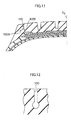
- the defense groove as a narrow groove must have a relatively small radius of curvature of the bottom portion thereof (about 1 to 3 mm). As a result, as shown in Fig. 11, a problem arises in that, due to the rubber deterioration and the like due to traveling, cracks 102A, B and the like may be relatively easily generated in the bottom portion of a defense groove 100 provided in the tread.
- a tire has been conceived of in which the tread rubber is improved, and, as shown in Fig. 12, the vicinity of the groove bottom of the defense groove 100 is formed to have a substantially circular cross-section.
- a groove fence 104 which is formed from a pair of projections 102, is provided within a circumferential direction main groove 100, a concentration of shearing stress arises at the bottom portion of the groove bottom between the respective projections 102, due to the dynamic strain (strain which enlarges and reduces the groove width) at the time the tire rolling, whereby a problem arises in that a crack 106 forms.
- a first object of the present invention is to provide a tire which is applied to vehicles for heavy loads, in which tire the generation of cracks from the groove bottoms of circumferential direction grooves is suppressed and the growth of cracks which have been generated is suppressed.
- a second object of the present invention is to provide a device for extruding an unvulcanized tread rubber for a tire, which device extrusion molds an unvulcanized rubber member to be used for producing a tire which is in accordance with the above first object.
- a third object of the present invention is to provide a method of extruding an unvulcanized tread rubber, for producing a tire which is in accordance with the above first object.
- a tire in a first aspect of the present invention, comprises a tread; and a plurality of grooves provided in the tread, wherein, at at least one of the grooves, a crack suppressing rubber having crack resistance which is superior to crack resistance of surrounding rubber is disposed so as to reinforce a vicinity of a groove bottom.
- the crack suppressing rubber which has crack resistance which is superior to that of the surrounding rubber (the surrounding rubber being the rubber forming the main portion of the tread), is disposed so as to reinforce a vicinity of the groove bottom of the groove. Accordingly, the generation of cracks from a vicinity of the groove bottom, at a time when land portions at the side of the groove are greatly deformed due to a large lateral force or to recesses and projections on the road surface or the like, can be suppressed, and thus the advance or growth of generated cracks can be suppressed.
- the groove of the tire of the first aspect is a circumferential groove which extends in a circumferential direction and which is disposed at an outermost side in a widthwise direction of the tire.
- the crack suppressing rubber which has crack resistance which is superior to that of the surrounding rubber (the surrounding rubber being the rubber forming the main portion of the tread), is disposed so as to reinforce a vicinity of the groove bottom of the circumferential groove at the outermost side in the widthwise direction of the tire. Accordingly, the generation of cracks from a vicinity of the groove bottom at a time when the land portions, which are disposed at the outer side of the circumferential groove at the outermost side in the widthwise direction of the tire, are greatly deformed due to a large lateral force or due to recesses and projections on the road surface or the like, can be suppressed. As a result, the advance or growth of generated cracks can be suppressed.
- elongation-at-break of the crack suppressing rubber of the tire is 130% or more of elongation-at-break of a rubber generally forming a tread surface of the tread.
- the elongation-at-break of the crack suppressing rubber is 130% or more of the elongation-at-break of the rubber which forms the tread surface of the tread, whereby the generation of cracks can be reliably suppressed.
- elongation-at-break means the elongation-at-break (%) as put forth in the JIS standard vulcanized rubber tensile test method (K6251).
- the rubber forming the tread surface of the tread is the cap rubber.
- the crack suppressing rubber of the tire is provided at 10% or more of a groove depth dimension, at least from the groove bottom toward an opening portion of the groove.
- the crack suppressing rubber is preferably provided over a range of 10% or more of the groove depth dimension, at least from the groove bottom toward the groove opening portion.
- the crack suppressing rubber may be provided so as to reinforce the entire circumferential direction groove from the groove bottom to the groove opening portion.
- a thickness of the crack suppressing rubber of the tire is 1 mm or more.
- the thickness of the crack suppressing rubber is preferably 1 mm or more.
- the thickness of the crack suppressing rubber of the tire is greater than or equal to 2 mm and less than or equal to 5 mm.
- the crack suppressing effect is further improved.
- the thickness of the crack suppressing rubber exceeding 5 mm is not preferable because the balance with the other properties, such as the heat generation property, deteriorates.
- the tire further comprises a projection which extends from at least one of the groove bottom and a groove wall of the groove toward an inner side of the groove, an end portion of the projection being disposed in the vicinity of the groove bottom.
- the grooves formed in the tread tend to cause columnar resonance due to rolling of the tire. Therefore, the noise generated by the tire may become worse as a result of the provision of the grooves. However, by providing projections in the grooves, the columnar resonance can be significantly reduced.
- the crack suppressing rubber which has excellent crack resistance, is disposed in the vicinity of the groove bottom, generation of cracks due to a concentration of stress can be reliably prevented.
- a device for extruding an unvulcanized tread rubber for a tire comprises: a first extruding device main body which extrudes a first unvulcanized rubber which forms a main portion of a tread; a second extruding device main body which extrudes a second unvulcanized rubber which is different from the first unvulcanized rubber; an extrusion head which connects respective distal end portions of the first extruding device main body and the second extruding device main body; and a flow path forming mold which, at a distal end portion of the extrusion head, guides the first unvulcanized rubber and the second unvulcanized rubber out to a mouthpiece, wherein the flow path forming mold has: a first flow path through which the first unvulcanized rubber flows toward the mouthpiece; and a second flow path through which the second unvulcanized rubber flows toward the mouthpiece, and a rubber discharging portion of the second flow path opens
- the first unvulcanized rubber is extruded from the first extruding device main body
- the second unvulcanized rubber is extruded from the second extruding device main body.
- the first unvulcanized rubber moves toward the mouthpiece via the first flow path of the flow path forming mold
- the second vulcanized rubber moves toward the mouthpiece via the second flow path of the flow path forming mold
- the rubber discharging portion of the second flow path is open at an intermediate portion of the first flow path, which intermediate portion is set apart from the path wall surfaces of the first flow path (i.e., is an interior portion of the flow path between the path wall surfaces thereof).
- an unvulcanized rubber member for a tire in which, as seen in cross-section, the second unvulcanized rubber is disposed within the first unvulcanized rubber, can be extruded from the mouthpiece.
- the intermediate region here may be any region provided that it is a region which is within the first flow path and which is set apart from the path wall surfaces of the first flow path, as seen in a cross-section orthogonal to the flow of rubber in the first flow path.
- the rubber discharging portion opens at a position which is 50 mm or less from the mouthpiece.
- the rubber discharging portion is preferably open at a position which is 50 mm or less from the mouthpiece.
- a method of extruding an unvulcanized rubber for a tire which, by using an extrusion device, extrudes, into a first unvulcanized rubber which forms a main portion of a tread, a second unvulcanized rubber which is different than the first unvulcanized rubber, comprises the steps of: (a) extruding the second unvulcanized rubber into a flow of the first unvulcanized rubber at an upstream side of a mouthpiece of the extruding device; and (b) extruding, from the mouthpiece, an unvulcanized tread rubber for a tire in which the second unvulcanized rubber is disposed within the first unvulcanized rubber.
- the second unvulcanized rubber is extruded into the flow of the first unvulcanized rubber at the upstream side of the mouthpiece.
- a first embodiment of a pneumatic tire of the present invention will be described in accordance with Figs. 1 through 5.
- circumferential direction main grooves 14 are formed in a tread 12 (having a tread width W) of a pneumatic tire 10 of the present embodiment, along a circumferential direction of the tire (the direction of arrow S), at both sides in the widthwise direction (i.e. the direction of arrow L and the direction of arrow R) of a tire equatorial plane CL.
- Circumferential direction main grooves 16, which extend linearly along the circumferential direction of the tire, are formed at the outer sides, in the widthwise direction of the tire, of the circumferential direction main grooves 14.
- a plurality of stone-catching preventing projections 18 are formed along the longitudinal directions of the grooves, at the bottom portions of the circumferential direction grooves 14. The position of the peak portion of the stone-catching preventing projection 18 is set to be lower than the tread surface of the tread 12.
- a plurality of short sipes 26, which extend in the axial direction of the tire, are formed in the circumferential direction of the tire at the tread surface side edge portions of the center rib 22, which edge portions are at the circumferential direction main groove 14 sides.
- a plurality of short sipes 32 which extend in the axial direction of the tire, are formed, in the circumferential direction of the tire, at the tread surface side edge portions of the second rib 28, which edge portions include those at the circumferential direction main groove 14 side and those at the circumferential direction main groove 16 side.
- a plurality of short sipes 36 which extend in the axial direction of the tire, are formed in the circumferential direction of the tire, at the tread surface side edge portion of a shoulder rib 34, which edge portion is at the circumferential direction main groove 16 side.
- a circumferential direction narrow groove 38 which extends linearly along the circumferential direction near the shoulder portion and which is narrower than the circumferential direction main groove 16, is formed in the shoulder rib 34.
- a groove width W1 of the circumferential direction narrow groove 38 is a groove width which is 3% or less than the tread width W, so that a sudden change in ground-contact pressure in the shoulder rib 34 does not arise.
- the groove width W1 is about 0.3 to 2% of the tread width W so that the groove walls substantially contact one another at the ground-contact region at the time when the tire is rolling while loaded.
- a groove depth D1 must be 30% or more of a depth D of the adjacent circumferential direction main groove 16, and preferably is less than or equal to 100% of the depth D.
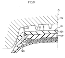
- the tread 12 of the present embodiment has a so-called cap-base structure formed from a cap rubber 12A which is at the tread surface side, and a base rubber 12B which is disposed at the inner side of the cap rubber 12A in the radial direction of the tire.
- the types of rubbers of the cap rubber 12A and base rubber 12B are as in conventional art.
- the rubber is selected mainly in consideration of the partial wear resistance
- the rubber is selected in consideration of heat build-up durability.
- a vicinity of the groove bottom of the circumferential direction narrow groove 38 is reinforced by a crack suppressing rubber 12C which is for suppressing the generation and the growth of cracks.
- the crack suppressing rubber 12C is a rubber whose elongation-at-break is greater than that of the cap rubber 12A.
- the crack suppressing rubber 12C is preferably provided over a range which is 10% or more of the groove depth D1, from the groove bottom (the deepest portion) of the circumferential direction narrow groove 38 toward the opening portion of the groove.
- a thickness t1 of the crack suppressing rubber 12C is preferably 1 mm or more in the vicinity of the groove bottom (at least at the inner side, in the radial direction of the tire, of the groove bottom, and at the tire widthwise direction sides of the groove bottom). Note that the thickness t1 of the crack suppressing rubber 12C is more preferably greater than or equal to 2 mm and less than or equal to 5 mm.
- the thickness t1 of the crack suppressing rubber 12C exceeding 5 mm is not preferable because the balance with the other properties, such as the heat generation property, deteriorates.
- the elongation-at-break of the crack suppressing rubber 12C is preferably 130% or more of that of the cap rubber 12A forming the tread surface of the tread 12.
- the crack suppressing rubber 12 is preferably exposed at the groove walls in the vicinity of the groove bottom of the circumferential direction narrow groove 38.
- the cap rubber 12A may be provided at the groove wall sides of the crack suppressing rubber 12C provided that the cap rubber 12A is thin there.
- the cap rubber 12A is disposed in the form of a thin film at the groove wall sides of the crack suppressing rubber 12C.
- a thickness t of the thin-film-form cap rubber 12A which reinforces the crack suppressing rubber 12C at the groove wall sides must be 1 mm or less, and is preferably 0.5 mm or less.
- the reason why the cap rubber 12A is disposed at the groove wall sides of the crack suppressing rubber 12C is that the unvulcanized tread 12, which has the cross-sectional configuration shown in Fig. 3, is used.
- the lower side is the unvulcanized base rubber 12
- the upper side is the unvulcanized cap rubber 12A
- the internal structure, other than the tread 12, of the pneumatic tire 10 of the present embodiment is the same as that of an ordinary radial tire for heavy loading.
- the circumferential direction narrow grooves 38 appropriately reduce the ground-contact pressure applied to the shoulder ribs 34, and make the ground-contact pressure distribution of the shoulder ribs 34 more uniform.
- generation of local wear which is a main type of partial wear, is suppressed, and the growth or advance of generated local wear toward the inner sides in the axial direction of the tire, of the shoulder ribs 34 (i.e., toward the tire equatorial plane CL sides of the shoulder ribs 34) is suppressed.
- the crack suppressing rubbers 12C which have elongation-at-break which is superior to that of the cap rubber 12A, are disposed so as to reinforce vicinities of the groove bottoms of the circumferential direction narrow grooves 38.
- the generation of cracks from vicinities of the groove bottoms, at the time when the land portions at the outer sides of the circumferential direction narrow grooves 38 deform greatly due to great lateral force or due to recesses and projections at the road surface or the like can be suppressed, and the growth of cracks which have been generated can be suppressed.
- breaking-off of the land portions at the outer sides of the circumferential direction narrow grooves 38, and separation of the tread 12 can be suppressed.
- break-at-elongation of the crack suppressing rubber 12C is less than 130% of that of the cap rubber 12A, the effects of suppressing generation of cracks and growth of cracks are insufficient.
- the structure of the tread 12 is a cap-base structure.
- the tread 12 may be structured by a single rubber, or may be formed by three or more types of rubber.
- cross-sectional configuration of the circumferential direction narrow groove 38 may be flask-shaped as shown in Fig. 12.
- the crack suppressing rubber 12C is disposed in the vicinity of the groove bottom of the circumferential direction narrow groove 38.
- the crack suppressing rubber 12C may be provided at any type of groove at which cracks are relatively easily generated in the vicinity of the groove bottom and the generated cracks relatively easily grow larger.
- FIG. 6 A second embodiment of the pneumatic tire of the present invention will be described in accordance with Fig. 6. Note that structures which are the same as those of the first embodiment are denoted by the same reference numerals, and description thereof is omitted.
- the circumferential direction main grooves 14 and the circumferential direction main grooves 16 are formed in the tread 12 (having the tread width W) of the pneumatic tire 10 of the present embodiment.
- stone-catching preventing projections are not provided at the bottom portions of the circumferential direction main grooves 14 of the present embodiment.
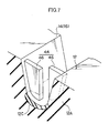
- Groove fences 44 such as that shown in Fig. 7, are formed in the circumferential direction main grooves 14 and the circumferential direction main grooves 16.
- the groove fences 44 are provided at intervals such that at least one groove fence 44 is disposed in each circumferential direction main groove, within the ground-contact plane formed at the time the tire is running.
- the groove fence 44 of the present embodiment is formed by a pair of projections 46 which project toward the groove center from the opposing groove walls.
- the one projection 46 and the other projection 46 are offset in the circumferential direction of the tire so as not to contact each other at the time of running under load.
- the crack suppressing rubber 12C is provided at the groove bottom of the circumferential direction main groove 14.
- the crack suppressing rubber 12C is provided so as to be exposed at least at the groove bottom, and preferably has a gauge of 1 mm or more.
- the crack suppressing rubber 12C may be provided in at least a vicinity of the groove bottom. Or, as shown in Fig. 8, all of the groove walls and the projections 46 may be made from the crack suppressing rubber 12C. Or, as shown in Figs. 9 and 10, portions of the groove walls and the projections 46 may be made from the crack suppressing rubber 12C.
- Example Tire The structure was the same as the structure of the first embodiment.
- the crack suppressing rubber exhibited an elongation-at-break which was 140% of the elongation-at-break of the cap rubber.
- the thickness of the crack suppressing rubber was 3 mm (on average), and the height (at the top position) thereof from the groove bottom was 40% of the groove depth (i.e., was 6 mm). In the vicinity of the groove bottom, the thickness of the crack suppressing rubber was 2 mm.
- the thickness t of the thin-film-form cap rubber reinforcing the crack suppressing rubber was 0.5 mm or less.
- the conventional tire was a tire having a structure in which the crack suppressing rubber was removed from the Example Tire.
- a device 1000 for extruding an unvulcanized tread rubber for a tire of the present embodiment has four extruder main bodies 110, 120, 130, 140, and an extrusion head 150 which is connected to the distal end portions of the extruder main bodies 110, 120, 130, 140.
- the extruder main bodies 110, 120, 130 correspond to the first extruding device main bodies of the present invention
- the extruder main body 140 corresponds to the second extruding device main body of the present invention.
- a plurality of first extruding device main bodies may be provided.
- the extruder main bodies 110, 120, 130, 140 are provided, respectively, with hoppers 110h, 120h, 130h, 140h for supplying unvulcanized rubber, which are positioned at the rear sides of the extruder main bodies 110, 120, 130, 140.
- Unvulcanized rubbers A, B, C, D which are four types of unvulcanized rubbers having different blended compositions, are continuously supplied to the extruder main bodies 110, 120, 130, 140 from the hoppers 110h, 120h, 130h, 140h, respectively.
- the unvulcanized rubbers A, B, C, D are guided out toward the extrusion head 150 by screws (not shown) which are driven to rotate.
- Fig. 20 illustrates the cross-sectional configuration of an integral composite unvulcanized tread rubber 400 which is extrusion molded by the device 1000 for extruding an unvulcanized tread rubber for a tire.
- the unvulcanized rubber A is the unvulcanized rubber which becomes the cap rubber at the tread of the manufactured product tire.
- Unvulcanized rubber B is the unvulcanized rubber which becomes the base rubber of the tread.
- Unvulcanized rubber C is the small pieces of unvulcanized rubber which are called mini-sidewall rubbers which are positioned at the sides of the tread surface side tread rubber of the manufactured product tire, and which are joined to the sidewall rubbers (not shown).
- Unvulcanized rubber D is the unvulcanized rubber for crack suppression which is disposed in vicinities of groove bottoms of the circumferential direction grooves formed in the tread of the manufactured product tire.
- the extrusion head 150 is equipped with a mouthpiece 160 which is positioned at the distal end portion of the extrusion head 150 (i.e., the downstream-side end portion of the extrusion head 150 in the direction of extruding the unvulcanized rubbers A, B, C, D) .
- the extrusion head 150 has flow paths 150a, 150b, 150c, 150d for the unvulcanized rubbers A, B, C, D which are directed toward the mouthpiece 160 from the extrusion outlets of the respective extruder main bodies 110, 120, 130, 140.
- a forming means 170 which is for forming an integral composite unvulcanized tread rubber 400 in which the unvulcanized rubbers A, B, C, D respectively have predetermined cross-sectional configurations, is accommodated so as to be freely removable, between the terminal ends of the flow paths 150a, 150b, 150c, 150d and the mouthpiece 16.
- the unvulcanized rubbers A, B, C, D are extruded in direction R.
- the forming means 170 has a back die 160b, a die holder 180, and a back die holder 190.
- the back die 160b forms a pair with the mouthpiece 160, and serves to separately form the bottom portion of the extruded outer contour configuration of the mouthpiece 160.
- the die holder 180 holds and fixes the mouthpiece 160 to the extrusion head 150.
- the back die holder 190 holds and fixes the back die 160b to the extrusion head 150.
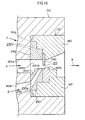
- the forming means 170 has a first flow path forming mold 220 which is disposed between the mouthpiece 160 and the terminal ends of the flow paths 150a, 150b, 150c of the extrusion head 150; a second flow path forming mold 240 and a third flow path forming mold 230 which are provided such that the first flow path forming mold 220 is disposed therebetween; and a fourth flow path forming mold 260 which is provided so as to cross the first flow path forming mold 220.
- the first flow path forming mold 220 has a flow path 220a which is directed toward the mouthpiece 160 and which is for the unvulcanized rubber A.
- the second flow path forming mold 240 has a flow path 240c which is directed toward the mouthpiece 160 and which is for the unvulcanized rubber C.
- the third flow path forming mold 230 has a flow path 230b which is directed toward the mouthpiece 160 and which is for the unvulcanized rubber B.
- Fig. 14 is a perspective view, as seen at an incline from below at the upstream side in the flowing direction of the rubber, of the first flow path forming mold 220, the second flow path forming mold 240, the third flow path forming mold 230, the fourth flow path forming mold 260, and the mouthpiece 160.
- the first flow path forming mold 220 has the flow path 220a, which is oriented in the direction of the arrow representing the unvulcanized rubber A.
- the first flow path forming mold 220 has a cut-out concave portion 220A which runs along the flow path 220a, and which opens to both the back surface of the mouthpiece 160 and to a laterally-long space 210 between the mouthpiece 160 and the back die 160b.
- the second flow path forming mold 240 has the flow path 240c, which is oriented in the direction of the arrow representing the unvulcanized rubber C.
- the flow path 240c opens to and connects with the cut-out concave portion 220A of the first flow path forming mold 220.
- the third flow path forming mold 230 has the flow path 230b, which is oriented in the direction of the arrow representing the unvulcanized rubber B.
- the third flow path forming mold 230 has an inclined cut-out concave portion 250 which runs along the flow path 230b and which opens to the back surface of the mouthpiece 160 and to the laterally-long space 210, with the first flow path forming mold 220 serving as a dam thereof.
- a T-shaped cut-out portion 270 is formed in the second flow path forming mold 240.
- a groove 280 is formed in the first flow path forming mold 220.
- the fourth flow path forming mold 260 has a base portion 290 and a hollow sheath 300.
- the base portion 290 is removably fit with the T-shaped cut-out portion 270 of the second flow path forming mold 240.
- the hollow sheath 300 which is long, narrow, and thin, extends from the base portion 290.
- the hollow sheath 300 has, at the distal end thereof, an introduction opening 310 for the unvulcanized rubber D.
- the intermediate portion of the hollow sheath 300 is removably fit in the groove 280 of the first flow path forming mold 220.
- the introduction opening 310 side portion of the hollow sheath 300 is removably fit in a concave portion 320 formed in the cut-out portion 250 of the third flow path forming mold 230.
- the hollow sheath 300 of the fourth flow path forming mold 260 is formed in a taper shape which narrows toward the mouthpiece 160 side.
- the hollow sheath 300 has an internal space 330 which receives the unvulcanized rubber D which flows through the introduction opening 310, and has an opening portion 340 at the mouthpiece 160 side.
- the fourth flow path forming mold 260 has a flow path 260d, for the unvulcanized rubber D, which extends from the introduction opening 310 through the internal space 330 to the opening portion 340.
- the opening portion 340 is circular in the present embodiment, the present invention is not limited to the same.
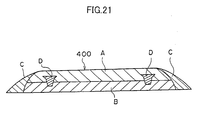
- the configuration of the opening portion 340 may be substantially trapezoidal so that the unvulcanized rubber D in the integral composite unvulcanized tread rubber 400 has the cross-sectional configuration shown in Fig. 21 (second embodiment) .
- the configuration of the opening portion 340 is substantially the same as the cross-sectional configuration of the extruded unvulcanized rubber D.
- the distance (L in Fig. 17) from the opening portion 340 to the mouthpiece 160 is preferably 0 to 50 mm.
- the unvulcanized rubbers A, B, C, D are extruded toward the mouthpiece 160 by the extruder main bodies 110, 120, 130, 140.
- the unvulcanized rubber A heads toward the mouthpiece 160 via the flow path 220a, the unvulcanized rubber B heads toward the mouthpiece 160 via the flow path 230b, and the unvulcanized rubber C heads toward the mouthpiece 160 via the flow path 240c.
- the unvulcanized rubber D which has a circular cross-sectional configuration, is discharged into the flow of the unvulcanized rubbers A, B, C from the opening portion 340 which is disposed at the upstream side of the mouthpiece 160 and in the vicinity of the mouthpiece 160.
- the integral composite unvulcanized tread rubber 400 which has the cross-sectional configuration shown in Fig. 20, can be continuously extrusion molded.
- the integral composite unvulcanized tread rubber 400 which is used in the tread of a cap-base structure, is extrusion molded.
- the present invention may of course be applied as well to an extruding device which extrusion molds an integral composite unvulcanized tread rubber for a tread of another structure having a different cross-sectional configuration.
- Fig. 21 (the second embodiment) is an example of an integral composite unvulcanized tread rubber having a cross-sectional configuration which is different than the cross-sectional configuration shown in Fig. 20.
- an unvulcanized rubber member for a tire which member is for forming a tread in which the generation of cracks from groove bottoms of circumferential direction grooves and the growth of generated cracks can be reliably suppressed.
Landscapes
- Engineering & Computer Science (AREA)
- Mechanical Engineering (AREA)
- Tires In General (AREA)
- Extrusion Moulding Of Plastics Or The Like (AREA)
- Tyre Moulding (AREA)
Abstract
Description
Accordingly, the generation of cracks from a vicinity of the groove bottom, at a time when land portions at the side of the groove are greatly deformed due to a large lateral force or to recesses and projections on the road surface or the like, can be suppressed, and thus the advance or growth of generated cracks can be suppressed.
| Conventional example | Example | |
| Ratio of elongation-at-break Crack suppressing rubber/cap rubber | - | 180% |
| Tears | some | None |
Claims (18)
- A tire comprising:wherein, at at least one groove of the plurality of grooves, a crack suppressing rubber having crack resistance which is superior to crack resistance of surrounding rubber is disposed so as to reinforce a vicinity of a groove bottom.a tread; anda plurality of grooves provided in the tread,
- A tire according to claim 1, wherein the groove at which the crack suppressing rubber is disposed is a circumferential direction groove which extends in a circumferential direction and which is disposed at an outermost side in a widthwise direction of the tire.
- A tire according to claim 1, wherein elongation-at-break of the crack suppressing rubber is 130% or more of elongation-at-break of a rubber forming a tread surface of the tread.
- A tire according to claim 1, wherein the crack suppressing rubber is provided at 10% or more of a groove depth dimension, at least from the groove bottom toward an opening portion of the groove.
- A tire according to claim 1, wherein a thickness of the crack suppressing rubber is 1 mm or more.
- A tire according to claim 5, wherein the thickness of the crack suppressing rubber is greater than or equal to 2 mm and less than or equal to 5 mm.
- A tire according to claim 1, further comprising a projection which extends from at least one of the groove bottom and a groove wall of the at least one groove toward an inner side of the groove, an end portion of the projection being disposed in the vicinity of the groove bottom.
- A tire according to claim 7, wherein the projection is formed by a pair of projections which project toward a center of the groove from both opposing groove walls.
- A tire according to claim 8, wherein one projection and another projection are disposed so as to be offset in a circumferential direction of the tire.
- A tire according to claim 1, wherein the crack suppressing rubber is exposed at least at the groove bottom.
- A device for extruding an unvulcanized tread rubber for a tire, comprising:wherein the flow path forming mold has:a first extruding device main body which extrudes a first unvulcanized rubber which forms a main portion of a tread;a second extruding device main body which extrudes a second unvulcanized rubber which is different from the first unvulcanized rubber;an extrusion head which connects respective distal end portions of the first extruding device main body and the second extruding device main body; anda flow path forming mold which, at a distal end portion of the extrusion head, guides the first unvulcanized rubber and the second unvulcanized rubber out to a mouthpiece,a first flow path through which the first unvulcanized rubber flows toward the mouthpiece; anda second flow path through which the second unvulcanized rubber flows toward the mouthpiece,and a rubber discharging portion of the second flow path opens at an intermediate portion of the first flow path, which intermediate portion is set apart from path wall surfaces of the first flow path and is a flow path interior.
- A device for extruding an unvulcanized tread rubber for a tire according to claim 11, wherein the rubber discharging portion of the second flow path opens at the first flow path at an upstream side of the mouthpiece and in the vicinity of the mouthpiece.
- A device for extruding an unvulcanized tread rubber for a tire according to claim 11, wherein the rubber discharging portion opens at a position which is 50 mm or less from the mouthpiece.
- A device for extruding an unvulcanized tread rubber for a tire according to claim 11, wherein a configuration of the rubber discharging portion of the second flow path is a configuration corresponding to a manufactured product configuration of the second unvulcanized rubber.
- A method of extruding an unvulcanized rubber for a tire which, by using an extrusion device, extrudes, into a first unvulcanized rubber which forms a main portion of a tread, a second unvulcanized rubber which is different than the first unvulcanized rubber, the method comprising the steps of:(a) extruding the second unvulcanized rubber into a flow of the first unvulcanized rubber at an upstream side of a mouthpiece of the extruding device; and(b) extruding, from the mouthpiece, an unvulcanized tread rubber for a tire in which the second unvulcanized rubber is disposed within the first unvulcanized rubber.
- A method of extruding an unvulcanized rubber for a tire according to claim 15, wherein the step of extruding the second unvulcanized rubber into the flow of the first unvulcanized rubber includes a step of extruding the second unvulcanized rubber into an interior portion of the flow of the first unvulcanized rubber, the interior portion being set apart from both widthwise direction ends of the flow path of the first unvulcanized rubber.
- A method of extruding an unvulcanized rubber for a tire according to claim 15, wherein the step of extruding the second unvulcanized rubber into the flow of the first unvulcanized rubber includes a step of extruding the second unvulcanized rubber in the vicinity of the mouthpiece.
- A method of extruding an unvulcanized rubber for a tire according to claim 17, wherein the step of extruding the second unvulcanized rubber into the flow of the first unvulcanized rubber includes a step of extruding the second unvulcanized rubber at a position which is 50 mm or less from the mouthpiece.
Priority Applications (1)
| Application Number | Priority Date | Filing Date | Title |
|---|---|---|---|
| EP06026158A EP1759889A3 (en) | 2001-03-12 | 2002-03-11 | Tire, device for extruding unvulcanized tread rubber for the tire, and method of extruding unvulcanized tread rubber for the tire |
Applications Claiming Priority (6)
| Application Number | Priority Date | Filing Date | Title |
|---|---|---|---|
| JP2001069480 | 2001-03-12 | ||
| JP2001069480A JP2002264200A (en) | 2001-03-12 | 2001-03-12 | Unvulcanized tread rubber extruder for tire and unvulcanized tread rubber extrusion method for tire |
| JP2001070739 | 2001-03-13 | ||
| JP2001070739 | 2001-03-13 | ||
| JP2002022766 | 2002-01-31 | ||
| JP2002022766A JP2002337515A (en) | 2001-03-13 | 2002-01-31 | tire |
Related Child Applications (1)
| Application Number | Title | Priority Date | Filing Date |
|---|---|---|---|
| EP06026158A Division EP1759889A3 (en) | 2001-03-12 | 2002-03-11 | Tire, device for extruding unvulcanized tread rubber for the tire, and method of extruding unvulcanized tread rubber for the tire |
Publications (3)
| Publication Number | Publication Date |
|---|---|
| EP1241026A2 true EP1241026A2 (en) | 2002-09-18 |
| EP1241026A3 EP1241026A3 (en) | 2003-07-23 |
| EP1241026B1 EP1241026B1 (en) | 2007-03-07 |
Family
ID=27346220
Family Applications (2)
| Application Number | Title | Priority Date | Filing Date |
|---|---|---|---|
| EP02251699A Expired - Lifetime EP1241026B1 (en) | 2001-03-12 | 2002-03-11 | Tire |
| EP06026158A Withdrawn EP1759889A3 (en) | 2001-03-12 | 2002-03-11 | Tire, device for extruding unvulcanized tread rubber for the tire, and method of extruding unvulcanized tread rubber for the tire |
Family Applications After (1)
| Application Number | Title | Priority Date | Filing Date |
|---|---|---|---|
| EP06026158A Withdrawn EP1759889A3 (en) | 2001-03-12 | 2002-03-11 | Tire, device for extruding unvulcanized tread rubber for the tire, and method of extruding unvulcanized tread rubber for the tire |
Country Status (4)
| Country | Link |
|---|---|
| US (2) | US20020157747A1 (en) |
| EP (2) | EP1241026B1 (en) |
| DE (1) | DE60218556T2 (en) |
| ES (1) | ES2282373T3 (en) |
Cited By (6)
| Publication number | Priority date | Publication date | Assignee | Title |
|---|---|---|---|---|
| WO2005108048A1 (en) * | 2004-05-10 | 2005-11-17 | Pirelli Tyre S.P.A. | Tyre manufacturing process |
| EP1435300A4 (en) * | 2001-10-11 | 2006-08-02 | Sumitomo Rubber Ind | Pneumatic tire |
| DE102007003062A1 (en) | 2007-01-20 | 2008-07-24 | Continental Aktiengesellschaft | Vehicle tires |
| EP2581238A1 (en) * | 2011-10-14 | 2013-04-17 | Sumitomo Rubber Industries, Ltd. | Heavy duty tire |
| EP3281780A4 (en) * | 2015-04-06 | 2018-11-07 | The Yokohama Rubber Co., Ltd. | Manufacturing method and manufacturing device for extruded rubber member |
| DE102009026337B4 (en) | 2009-08-05 | 2019-06-19 | Continental Reifen Deutschland Gmbh | Pneumatic vehicle tire and method for its manufacture |
Families Citing this family (16)
| Publication number | Priority date | Publication date | Assignee | Title |
|---|---|---|---|---|
| JP4611551B2 (en) * | 2001-03-12 | 2011-01-12 | 株式会社ブリヂストン | Unvulcanized rubber extrusion apparatus and unvulcanized rubber extrusion method |
| DE60229974D1 (en) * | 2001-05-16 | 2009-01-02 | Michelin Soc Tech | DEVICE FOR COEXTRUDING RUBBER MIXTURES |
| US7028734B2 (en) | 2003-06-24 | 2006-04-18 | The Goodyear Tire & Rubber Company | Truck tire with cap/base construction tread |
| BRPI0519261A2 (en) * | 2004-12-24 | 2009-01-06 | Soc Tech Michelin | Method and device for the manufacture of a tire |
| EP2147770B1 (en) * | 2007-03-27 | 2017-06-21 | Bridgestone Corporation | Unvulcanized rubber extruder and process for producing unvulcanized rubber |
| USD609166S1 (en) * | 2008-01-31 | 2010-02-02 | Continental Tire North America, Inc. | Tire tread |
| USD608728S1 (en) * | 2008-01-31 | 2010-01-26 | Continental Tire North America, Inc. | Tire tread |
| US8062017B2 (en) * | 2008-10-13 | 2011-11-22 | The Goodyear Tire & Rubber Co | Splice bar for tire tread extrusion apparatus |
| US8016580B2 (en) * | 2009-01-28 | 2011-09-13 | The Goodyear Tire & Rubber Company | Assembly and a method for extruding a tire component |
| DE102009026354A1 (en) | 2009-08-10 | 2011-02-17 | Continental Reifen Deutschland Gmbh | Vehicle pneumatic tire, particularly for commercial motor vehicles, comprises profiled tread which is divided into profile ribs or block rows by number of circumferential grooves |
| US20140034199A1 (en) * | 2012-07-31 | 2014-02-06 | Bridgestone Americas Tire Operations, Llc | Tire with laminate |
| US8919404B2 (en) * | 2012-09-12 | 2014-12-30 | The Goodyear Tire & Rubber Company | Rubber composition for tread groove reinforcement |
| JP6062252B2 (en) * | 2013-01-11 | 2017-01-18 | 株式会社ブリヂストン | Unvulcanized rubber extrusion equipment |
| FR3015365B1 (en) * | 2013-12-20 | 2016-01-15 | Michelin & Cie | PNEUMATIC TIRE TREAD FOR HEAVY VEHICLE TYPE GENIE CIVIL |
| US10427463B2 (en) | 2016-11-16 | 2019-10-01 | The Goodyear Tire & Rubber Company | Pneumatic tire having a dual layer tread |
| DE102019207732A1 (en) * | 2019-05-27 | 2020-12-03 | Continental Reifen Deutschland Gmbh | Process for producing an extruded, sulfur-crosslinkable rubber mixture and device for carrying out the process and the use thereof |
Family Cites Families (23)
| Publication number | Priority date | Publication date | Assignee | Title |
|---|---|---|---|---|
| DE1194721B (en) * | 1960-06-07 | 1965-06-10 | Phoenix Gummiwerke Ag | Treads of pneumatic motor vehicle tires |
| US3280427A (en) * | 1964-02-03 | 1966-10-25 | Cooper Tire & Rubber Co | Apparatus for extruding composite black and white rubber strips for white sidewall tires |
| US3444031A (en) * | 1964-04-22 | 1969-05-13 | Dow Chemical Co | Light screens and method of making the same |
| DE1729608A1 (en) * | 1968-02-16 | 1971-07-01 | Continental Gummi Werke Ag | Spray head for tire treads |
| US3761211A (en) * | 1972-01-17 | 1973-09-25 | Crompton & Knowles Corp | Multi-layer extrusion apparatus |
| US3820427A (en) * | 1972-09-01 | 1974-06-28 | Nederland Organ Voor Tolgepast | Method and device for cutting split film |
| US3804307A (en) * | 1972-09-11 | 1974-04-16 | D Johnston | Chain key holder |
| US4226274A (en) * | 1978-09-18 | 1980-10-07 | Awaya Herbert Y | Rubber tire with wear indicator therein |
| DE3325017C2 (en) * | 1983-07-11 | 1985-11-28 | Continental Gummi-Werke Ag, 3000 Hannover | Press head for the production of flat, coherent profile strands from plastic rubber or plastic mixtures of various compositions |
| US4683095A (en) * | 1985-05-08 | 1987-07-28 | The Uniroyal Goodrich Tire Company | Early progressive junction extrusion process and system |
| US5211898A (en) * | 1988-07-27 | 1993-05-18 | Tomy Machinery Manufacturing Co., Ltd. | Method and apparatus for feeding a plurality of molten resin jet streams into T die |
| US5017118A (en) * | 1989-06-16 | 1991-05-21 | The Goodyear Tire & Rubber Company | Apparatus for forming a coextrusion from extruded strips |
| JPH0794142B2 (en) * | 1990-07-03 | 1995-10-11 | 積水化学工業株式会社 | Apparatus for producing thermoplastic resin sheet and method for producing thermoplastic resin sheet using the same |
| JP2928108B2 (en) * | 1994-11-17 | 1999-08-03 | 三菱レイヨン株式会社 | Apparatus and method for manufacturing composite resin sheet |
| US5679196A (en) * | 1995-10-05 | 1997-10-21 | North American Rubber Thread Company, Inc. | Process of making rubber thread |
| IT1290520B1 (en) * | 1997-04-03 | 1998-12-04 | Pirelli | EXTRUSION METHOD AND APPARATUS FOR MAKING TREAD BANDS FOR VEHICLE TIRES |
| JP3815758B2 (en) * | 1997-10-06 | 2006-08-30 | 株式会社ブリヂストン | Heavy duty pneumatic tire |
| US6294119B1 (en) * | 1997-12-26 | 2001-09-25 | Bridgestone Corporation | Production of unvulcanized tread rubber for pneumatic tires |
| US6951233B1 (en) * | 1998-02-26 | 2005-10-04 | Compagnie Generale Des Etablissements Michelin-Michelin & Cie | Electrically conductive tire and apparatus and process for extruding elements which have been made conductive |
| WO2000053437A1 (en) * | 1999-01-21 | 2000-09-14 | Michelin Recherche Et Technique S.A. | Tire having a groove wall lining for reducing formation of anomalies causing subjective user dissatisfaction |
| JP4205256B2 (en) * | 1999-06-09 | 2009-01-07 | 東洋ゴム工業株式会社 | Extrusion molding method and apparatus for tire tread |
| US6447875B1 (en) * | 1999-07-30 | 2002-09-10 | 3M Innovative Properties Company | Polymeric articles having embedded phases |
| DE60229974D1 (en) * | 2001-05-16 | 2009-01-02 | Michelin Soc Tech | DEVICE FOR COEXTRUDING RUBBER MIXTURES |
-
2002
- 2002-03-11 ES ES02251699T patent/ES2282373T3/en not_active Expired - Lifetime
- 2002-03-11 EP EP02251699A patent/EP1241026B1/en not_active Expired - Lifetime
- 2002-03-11 US US10/093,378 patent/US20020157747A1/en not_active Abandoned
- 2002-03-11 EP EP06026158A patent/EP1759889A3/en not_active Withdrawn
- 2002-03-11 DE DE60218556T patent/DE60218556T2/en not_active Expired - Fee Related
-
2006
- 2006-03-21 US US11/384,278 patent/US20060157177A1/en not_active Abandoned
Cited By (9)
| Publication number | Priority date | Publication date | Assignee | Title |
|---|---|---|---|---|
| EP1435300A4 (en) * | 2001-10-11 | 2006-08-02 | Sumitomo Rubber Ind | Pneumatic tire |
| WO2005108048A1 (en) * | 2004-05-10 | 2005-11-17 | Pirelli Tyre S.P.A. | Tyre manufacturing process |
| DE102007003062A1 (en) | 2007-01-20 | 2008-07-24 | Continental Aktiengesellschaft | Vehicle tires |
| DE102009026337B4 (en) | 2009-08-05 | 2019-06-19 | Continental Reifen Deutschland Gmbh | Pneumatic vehicle tire and method for its manufacture |
| EP2581238A1 (en) * | 2011-10-14 | 2013-04-17 | Sumitomo Rubber Industries, Ltd. | Heavy duty tire |
| CN103042885A (en) * | 2011-10-14 | 2013-04-17 | 住友橡胶工业株式会社 | Heavy duty tire |
| CN103042885B (en) * | 2011-10-14 | 2016-05-18 | 住友橡胶工业株式会社 | Tyre for heavy load |
| EP3281780A4 (en) * | 2015-04-06 | 2018-11-07 | The Yokohama Rubber Co., Ltd. | Manufacturing method and manufacturing device for extruded rubber member |
| US11110676B2 (en) | 2015-04-06 | 2021-09-07 | The Yokohama Rubber Co., Ltd. | Manufacturing method and manufacturing device for extruded rubber member |
Also Published As
| Publication number | Publication date |
|---|---|
| EP1759889A3 (en) | 2007-03-28 |
| EP1241026A3 (en) | 2003-07-23 |
| DE60218556D1 (en) | 2007-04-19 |
| US20060157177A1 (en) | 2006-07-20 |
| ES2282373T3 (en) | 2007-10-16 |
| US20020157747A1 (en) | 2002-10-31 |
| DE60218556T2 (en) | 2007-11-22 |
| EP1759889A2 (en) | 2007-03-07 |
| EP1241026B1 (en) | 2007-03-07 |
Similar Documents
| Publication | Publication Date | Title |
|---|---|---|
| EP1241026B1 (en) | Tire | |
| EP0925903B1 (en) | Production of unvulcanized tread rubber for pneumatic tires | |
| EP3189985B1 (en) | Pneumatic tire | |
| EP1403098B1 (en) | Off the road tire | |
| US9561630B2 (en) | Tread including at least one wavy groove, and method for producing same | |
| JP4165836B2 (en) | Especially low rolling resistance tires for driving wheels of heavy duty vehicles | |
| EP2586627B1 (en) | Pneumatic tire | |
| US8453689B2 (en) | Tire vulcanizing die and pneumatic tire | |
| JPH0976710A (en) | Pneumatic tire, manufacturing method thereof, and tire molding die used for the same | |
| RU2003117444A (en) | RUNNING TRACK OF THE PROTECTOR OF THE PNEUMATIC TIRE AND FORMING ELEMENT OF VOLCANIZING FORM FOR SUCH RUNNING TRACK | |
| WO2008050545A1 (en) | Pneumatic tire | |
| US8312903B2 (en) | Truck tire | |
| CN106364261B (en) | pneumatic tire | |
| KR20110116977A (en) | Pneumatic tire | |
| US11446962B2 (en) | Tire | |
| JP2010012666A (en) | Tire molding die and pneumatic tire molded by this molding die | |
| US11207921B2 (en) | Pneumatic tire | |
| JP3405701B2 (en) | Pneumatic tire and tire vulcanizing mold | |
| US20240424837A1 (en) | Tire and tire tread | |
| EP4360910B1 (en) | Tire | |
| US11584169B2 (en) | Pneumatic tire | |
| JP2001163012A (en) | Pneumatic tire | |
| JP2002337515A (en) | tire | |
| JP2023092438A (en) | tire | |
| JPH0994831A (en) | Vulcanization mold and radial tire |
Legal Events
| Date | Code | Title | Description |
|---|---|---|---|
| PUAI | Public reference made under article 153(3) epc to a published international application that has entered the european phase |
Free format text: ORIGINAL CODE: 0009012 |
|
| AK | Designated contracting states |
Kind code of ref document: A2 Designated state(s): AT BE CH CY DE DK ES FI FR GB GR IE IT LI LU MC NL PT SE TR |
|
| AX | Request for extension of the european patent |
Free format text: AL;LT;LV;MK;RO;SI |
|
| PUAL | Search report despatched |
Free format text: ORIGINAL CODE: 0009013 |
|
| AK | Designated contracting states |
Designated state(s): AT BE CH CY DE DK ES FI FR GB GR IE IT LI LU MC NL PT SE TR |
|
| AX | Request for extension of the european patent |
Extension state: AL LT LV MK RO SI |
|
| 17P | Request for examination filed |
Effective date: 20040107 |
|
| AKX | Designation fees paid |
Designated state(s): DE ES FR GB IT |
|
| 17Q | First examination report despatched |
Effective date: 20040420 |
|
| GRAP | Despatch of communication of intention to grant a patent |
Free format text: ORIGINAL CODE: EPIDOSNIGR1 |
|
| RTI1 | Title (correction) |
Free format text: TIRE |
|
| GRAS | Grant fee paid |
Free format text: ORIGINAL CODE: EPIDOSNIGR3 |
|
| GRAA | (expected) grant |
Free format text: ORIGINAL CODE: 0009210 |
|
| AK | Designated contracting states |
Kind code of ref document: B1 Designated state(s): DE ES FR GB IT |
|
| REG | Reference to a national code |
Ref country code: GB Ref legal event code: FG4D |
|
| REF | Corresponds to: |
Ref document number: 60218556 Country of ref document: DE Date of ref document: 20070419 Kind code of ref document: P |
|
| REG | Reference to a national code |
Ref country code: ES Ref legal event code: FG2A Ref document number: 2282373 Country of ref document: ES Kind code of ref document: T3 |
|
| PLBE | No opposition filed within time limit |
Free format text: ORIGINAL CODE: 0009261 |
|
| STAA | Information on the status of an ep patent application or granted ep patent |
Free format text: STATUS: NO OPPOSITION FILED WITHIN TIME LIMIT |
|
| 26N | No opposition filed |
Effective date: 20071210 |
|
| PGFP | Annual fee paid to national office [announced via postgrant information from national office to epo] |
Ref country code: GB Payment date: 20080305 Year of fee payment: 7 Ref country code: IT Payment date: 20080321 Year of fee payment: 7 |
|
| PGFP | Annual fee paid to national office [announced via postgrant information from national office to epo] |
Ref country code: DE Payment date: 20080306 Year of fee payment: 7 Ref country code: ES Payment date: 20080331 Year of fee payment: 7 Ref country code: FR Payment date: 20080311 Year of fee payment: 7 |
|
| GBPC | Gb: european patent ceased through non-payment of renewal fee |
Effective date: 20090311 |
|
| REG | Reference to a national code |
Ref country code: FR Ref legal event code: ST Effective date: 20091130 |
|
| PG25 | Lapsed in a contracting state [announced via postgrant information from national office to epo] |
Ref country code: DE Free format text: LAPSE BECAUSE OF NON-PAYMENT OF DUE FEES Effective date: 20091001 |
|
| PG25 | Lapsed in a contracting state [announced via postgrant information from national office to epo] |
Ref country code: FR Free format text: LAPSE BECAUSE OF NON-PAYMENT OF DUE FEES Effective date: 20091123 Ref country code: GB Free format text: LAPSE BECAUSE OF NON-PAYMENT OF DUE FEES Effective date: 20090311 |
|
| REG | Reference to a national code |
Ref country code: ES Ref legal event code: FD2A Effective date: 20090312 |
|
| PG25 | Lapsed in a contracting state [announced via postgrant information from national office to epo] |
Ref country code: ES Free format text: LAPSE BECAUSE OF NON-PAYMENT OF DUE FEES Effective date: 20090312 |
|
| PG25 | Lapsed in a contracting state [announced via postgrant information from national office to epo] |
Ref country code: IT Free format text: LAPSE BECAUSE OF NON-PAYMENT OF DUE FEES Effective date: 20090311 |