EP1241008A2 - Firing chamber geometry for inkjet printhead - Google Patents
Firing chamber geometry for inkjet printhead Download PDFInfo
- Publication number
- EP1241008A2 EP1241008A2 EP02251624A EP02251624A EP1241008A2 EP 1241008 A2 EP1241008 A2 EP 1241008A2 EP 02251624 A EP02251624 A EP 02251624A EP 02251624 A EP02251624 A EP 02251624A EP 1241008 A2 EP1241008 A2 EP 1241008A2
- Authority
- EP
- European Patent Office
- Prior art keywords
- heat transducer
- firing chamber
- chamber
- entry
- ink
- Prior art date
- Legal status (The legal status is an assumption and is not a legal conclusion. Google has not performed a legal analysis and makes no representation as to the accuracy of the status listed.)
- Granted
Links
Images
Classifications
-
- B—PERFORMING OPERATIONS; TRANSPORTING
- B41—PRINTING; LINING MACHINES; TYPEWRITERS; STAMPS
- B41J—TYPEWRITERS; SELECTIVE PRINTING MECHANISMS, i.e. MECHANISMS PRINTING OTHERWISE THAN FROM A FORME; CORRECTION OF TYPOGRAPHICAL ERRORS
- B41J2/00—Typewriters or selective printing mechanisms characterised by the printing or marking process for which they are designed
- B41J2/005—Typewriters or selective printing mechanisms characterised by the printing or marking process for which they are designed characterised by bringing liquid or particles selectively into contact with a printing material
- B41J2/01—Ink jet
- B41J2/135—Nozzles
- B41J2/14—Structure thereof only for on-demand ink jet heads
- B41J2/14016—Structure of bubble jet print heads
- B41J2/14032—Structure of the pressure chamber
- B41J2/1404—Geometrical characteristics
-
- B—PERFORMING OPERATIONS; TRANSPORTING
- B41—PRINTING; LINING MACHINES; TYPEWRITERS; STAMPS
- B41J—TYPEWRITERS; SELECTIVE PRINTING MECHANISMS, i.e. MECHANISMS PRINTING OTHERWISE THAN FROM A FORME; CORRECTION OF TYPOGRAPHICAL ERRORS
- B41J2/00—Typewriters or selective printing mechanisms characterised by the printing or marking process for which they are designed
- B41J2/005—Typewriters or selective printing mechanisms characterised by the printing or marking process for which they are designed characterised by bringing liquid or particles selectively into contact with a printing material
- B41J2/01—Ink jet
- B41J2/135—Nozzles
- B41J2/14—Structure thereof only for on-demand ink jet heads
- B41J2002/14387—Front shooter
Definitions
- This invention relates to the construction of ink drop ejector components of printheads used in inkjet printing.
- An inkjet printer typically includes one or more cartridges that contain ink.
- the cartridge has discrete reservoirs of more than one color of ink.
- Each reservoir is connected via a conduit to a printhead that is mounted to the body of the cartridge.
- the reservoir may be carried by the cartridge or mounted in the printer and connected by a flexible conduit to the cartridge.
- the printhead is controlled for ejecting minute drops of ink from the printhead to a printing medium, such as paper, that is advanced through the printer.
- the printhead is usually scanned across the width of the paper.
- the paper is advanced, between printhead scans, in a direction parallel to the length of the paper.
- the ejection of the drops is controlled so that the drops form recognizable images on the paper.
- the ink drops are expelled through nozzles that are formed in a plate that covers most of the printhead.
- the nozzle plate is typically bonded atop an ink barrier layer of the printhead. That barrier layer is shaped to define ink chambers. Each chamber is in fluidic communication with and is adjacent to one or more nozzles through which ink drops are expelled from the chamber.
- the barrier layer and nozzle plate can be configured as a single member, such as a layer of polymeric material that has formed in it both the ink chambers and associated nozzles.
- Ink drops are expelled from each ink chamber by a heat transducer, which typically comprises a thin-film resistor.
- the resistor is carried on an insulated substrate, such as a conventional silicon die upon which has been deposited an insulation layer, such as silicon dioxide.
- the resistor is covered with suitable passivation and cavitation-protection layers.
- the resistor has conductive traces attached to it so that the resistor can be selectively driven (heated) with pulses of electrical current.
- the heat from the resistor is sufficient to form a vapor bubble in each ink chamber.
- the rapid expansion of the bubble propels a drop through the nozzle adjacent the ink chamber.
- the chamber is refilled, after each drop ejection, with ink that flows into the chamber through a channel that connects with the conduit of reservoir ink.
- the components of the printhead (such as the heat transducer and ink chamber) for ejecting drops of ink are oftentimes referred to as drop ejectors.
- the action of ejecting a drop of ink is sometimes referred to as "firing" the resistor or drop ejector.
- the ink chambers are hereafter referred to as firing chambers.
- the vapor bubble that propels the drop through the nozzle rapidly collapses after each firing. This rapid collapse of the vapor bubble can, over time, damage the heat transducer as a result of cavitation. Cavitation is a vapor pocket over the heat transducer. When the ink bubble breaks, the ink forms pressure spikes that erode the resistor surface over time. As a result, the resistor may short out.
- firing chambers in the past have been designed with sidewalls that ensure the flow of refill ink into the chamber will be somewhat unbalanced. That is, the flow of refill ink is limited to one or two directions (as opposed to flowing uniformly over the resistor from all sides) so that the flow of refill ink moves the collapsing bubble off of the center of the heat transducer.
- the type of firing chamber configurations of concern here can be generally characterized as "three-sided" firing chambers wherein the refill ink flows into the firing chamber through a single entry in the chamber.
- US Patent No. 4,794,410 describes such a three-sided configuration.
- the properties of the refill-ink flow in prior three-sided designs is such that the collapsing vapor bubble is swept from the center of the resistor and pushed against the back corners of the firing chamber as the bubble collapse completes.
- This configuration is useful for extending the life of the resistor by protecting the center of the heat transducer from cavitation effects. Damage to the resistor, however, can still occur since the portions of the firing chamber walls where final bubble collapse occurs is designed to be very close to the heat transducer.
- the present invention is directed to a firing chamber configuration for the drop ejectors of inkjet printheads that extends the life of the heat transducer by ensuring that bubble collapse occurs at a location well spaced from the heat transducer.
- the sidewalls of the firing chamber are shaped relative to the firing chamber entry in a manner such that a strong jet of inflow ink is provided for moving the collapsing vapor bubble from the center of the chamber and against a curved back wall of the firing chamber.
- the curved back wall is very near the heat transducer.
- the refill ink impinges on the back wall, divides, and is redirected away from the back wall toward pockets defined in the front of the chamber.
- the pockets are remote from the heat transducer.
- the refill ink urges the collapsing (bifurcated) bubble into the pockets where final collapse occurs away from the heat transducer.
- the pockets in the chamber are formed at the junctions of the chamber sidewalls and front parts of the chamber wall that extend from each side of the entry.
- opposing sidewalls of the firing chamber divergently extend from the back wall along the entire length of the sidewalls so that the greatest distance between the sidewalls (hence, the maximum width of the chamber) is at the junction of each sidewall with its respective front wall part.
- the pockets reside just inside and offset from the entry so that the inflow of refill ink bypasses the relatively quiescent pockets to impinge against the curved back wall, which redirects that flow along the sidewalls back toward the pockets by formation of an eddy current.
- the ink chamber configuration of the present invention provides a relatively strong inflow of refill ink for moving the collapsing bubble off the resistor, as well as remote (from the heat transducer) and relatively quiescent (from a flow perspective) pockets for receiving the bubble during its final stage of collapse so as to prevent cumulative damage to the heat transducer that might otherwise occur if the final bubble collapse occurred immediately adjacent to the resistor.
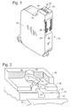
- Fig. 1 illustrates an inkjet printer cartridge 10 (shown inverted from its normal, installed position in a printer) that includes a plastic body 12 that defines a reservoir for ink.
- the cartridge body 12 is shaped to have a downwardly extending snout 14.
- a printhead 15 is attached to the underside of the snout 14.
- the exposed portion of the printhead is the exterior surface of a rectangular nozzle plate 16 that includes minute nozzles 18 (in this instance, two rows of nozzles) from which are ejected ink drops onto printing medium that is advanced through the printer.
- the printing medium advances very near to and generally substantially parallel to the nozzle plate 16.
- a thin circuit 20 is attached to the body 12 of the cartridge 10, partly on one side 22 of the cartridge adjacent the snout 14.
- the circuit extends from the side 22 and bends substantially in a perpendicular direction to extend across most of the underside 24 of the snout 14. However, the circuit does not cover the nozzle plate 16.
- the circuit 20 may be a thin polyimide material that carries conductive traces. The traces connect at one end to contact pads (not shown) in the printhead 15 that are near the long edges of the nozzle plate 16. The other ends of the traces terminate in contact pads 26 on the circuit, which pads mate with corresponding pads on a carriage (not shown).
- the circuit 20 carries control signals from a microprocessor-based printer controller to the individual components in the printhead 15 (primarily the heat transducers) that produce the ink drop ejection through the nozzles 18 of the nozzle plate 16.
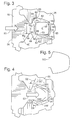
- the greatly enlarged cutaway view of Fig. 2 illustrates in perspective view a single firing chamber and associated nozzle of a printhead.
- the printhead comprises a substrate 32, such as a conventional silicon die upon which has been grown an insulation layer, such as silicon dioxide.
- a thin-film resistor (or heat transducer) 34 is formed on the substrate and is covered with suitable passivation and cavitation-protection layers, as is known in the art and described, for example, in US Patent No. 4,719,477, hereby incorporated by reference.
- a patterned layer of electrically conductive material (not shown) separately conducts the above-mentioned current pulses to the resistor 34 for heating the resistor.
- a firing chamber 36 substantially surrounds the resistor 34. The resistor vaporizes the ink in the firing chamber 36.
- each individual firing chamber 36 is primarily defined below by the resistor and along sides by a barrier layer 38.
- the barrier layer 38 is made from photosensitive material that is laminated onto the printhead substrate 32 and then exposed, developed, and cured.
- the barrier layer also defines an ink inlet channel 40 to each chamber through an opening in one of the walls of the barrier layer. Each channel 40 is tapered to form a pinch point or entry 44 through which ink flows into the chamber 36 as discussed more below.
- Ink drops are ejected through a nozzle 18 (one of which is shown cut away in Fig. 2) that is formed in the above mentioned nozzle plate 16 that covers most of the printhead 15.
- the nozzle plate 16 may be made from, for example, electrodeposited metal or a laser-ablated polyimide material, or any other suitable material.
- the nozzle plate 16 is bonded to the barrier layer 38 and aligned so that each firing chamber 36 is continuous with and in fluidic communication with one of the nozzles 18 from which the ink drops are ejected.
- the nozzle 18 is directly above and centered over its associated firing chamber 36.
- refill ink (generally depicted as arrow 50) flows from the cartridge reservoir through an ink feed slot 52 formed in the substrate 32 of the printhead and across an edge 54 of the feed slot into the channel 40.
- Fig. 2 depicts one exemplary firing chamber 36 that is next to the feed slot 52 that is formed in the center of the printhead substrate 32.
- the firing chambers are located on opposing sides of the center feed slot 52 such that the channels of all the firing chambers of the printhead open to the central ink-feed slot of the printhead.
- the refill ink flows over a side edge of the printhead rather than through the middle of printhead substrate 32.
- the channels of the chambers open to sides of the printhead rather than to the middle (not shown).
- the refill ink 50 flows through the entry 44 of the channel on its way to refill the chamber 36.
- the firing chamber configuration is designed to extend the life of the heat transducer 34 by ensuring that bubble collapse occurs at a location well spaced from the heat transducer. This is accomplished primarily by managing the flow characteristics of the refill ink. The particulars of the chamber configuration for doing this are explained next with reference to Figs. 3 - 5.
- Fig. 3 depicts one preferred embodiment of the present invention.
- This figure is a top view of a single drop ejector of an inkjet printhead.
- the nozzle plate is removed to show the configuration of the underlying firing chamber 36 (which is defined by the walls of the barrier layer or member 38), the heat transducer 34, and the associated channel 40.
- the embodiment of Fig. 3 shows part of the printhead substrate 32, including the edge 54 across which refill ink 50 flows to each chamber following each firing of a droplet via the instantaneous expansion of a vapor bubble as explained above.
- the inflow direction of refill ink is through the entry 44 toward a center 35 of the heat transducer 34.
- a line extending between a center 45 of the entry 44 and the center 35 of the heat transducer can be considered as an inflow direction, which is aligned with the center of arrow 50 (direction of ink flow) in Fig. 3.
- the vapor bubble 55 (dashed lines in Fig. 3) that caused the droplet ejection resides over the center 35 of the heat transducer 34 and begins to collapse substantially simultaneously with the inflow of the refill ink 50.
- the firing chamber 36 has a back wall 60 and two opposing sidewalls 62 surrounding the resistor 34.
- the back wall 60 and opposing sidewalls 62 are formed by the barrier layer 38.
- the back wall 60 is opposite the chamber entry 44.
- the opposing sidewalls 62 of the firing chamber 36 are shaped relative to the firing chamber entry 44 so that a strong jet of refill ink is provided for moving the collapsing vapor bubble 55 from the center of the chamber 36 and against the curved back wall 60 of the firing chamber.
- the back wall 60 is curved and is very near a back edge 70 of the generally square heat transducer 34.
- the back wall 60 of the chamber 36 is curved along a radius of about twice the width of the heat transducer 34 (which width may be, for example, about 12 ⁇ m), and spaced within about 3 ⁇ m of the rear edge 70.
- the inflow of refill ink 50 once across the center of the heat transducer, impinges on the curved back wall 60 and divides into what may be characterized as two flow components 50A and 50B.
- the collapsing vapor bubble is deflected off the back wall 60 and is sheared into two main components 55A, 55B.
- These bubble components are directed by the refill ink flow components 50A, 50B into two pockets 66 formed in the chamber 36 by the barrier walls as described next.
- the pockets 66 are located on each side of the chamber adjacent the channel entry 44.
- the flow components 50A, 50B of the refill ink do not interfere with the remaining inflow 50 of refill ink.
- the pockets form a zone of relative stagnation with respect to the flow 50.
- the pockets 66 are located just inside of each of two parts 68 of the barrier member 38 that define a front wall of the chamber 36. These front wall parts 68 extend from each side of the channel entry 44 into the chamber (Fig. 3).
- the pockets 66 of the firing chamber 36 provide a relatively quiescent portion of the re-filling chamber as compared to the refill ink inflow 50 moving through the entry 44 toward the heat transducer. Therefore, as the refill ink enters the chamber 36, it substantially bypasses the pockets 66 where the vapor bubbles are undergoing the final stages of collapse.
- the pockets 66 are defined in part by the sidewalls 62 of the chamber 36.
- the barrier member 38 is shaped so that the chamber sidewalls diverge relative to each other as they extend from the respective junctions (back comers 80) with the back wall 60.
- the divergence is continuous so that at front comers 82 of the firing chamber (that is, the junction of one of the sidewalls 62 with the adjacent front wall part 68) represents a widest part W C of the chamber 36 as measured perpendicular to the refill ink inflow direction.
- the maximum chamber width is more than 50% larger than the width of the heat transducer (again, measured perpendicular to inflow direction 50). Also, as shown in Fig. 3, this widest part of the chamber W C (hence, the location of the pockets) occurs between a front edge 74 of the heat transducer adjacent the entry 44 and the entry 44 of the chamber. As shown in Fig. 4, this location of the pockets 66 helps to ensure that the final stages of bubble collapse occur well away from the heat transducer. Put another way, the maximum firing chamber width W C is, preferably, more than 50% larger than a width W E of the entry 44, thereby to provide pockets 66 adequately large to accommodate bubble collapse without simultaneously interfering with the adjacent inflow 50 of refill ink.
- the front comers 82 and the back corners 80 are formed with small radii (and not sharp angles) so as to ensure smooth flow of the refill ink across those comers.
- the front wall parts 68 of the chamber join the sidewalls 62 to define the front corners 82 and shape the pockets 66.
- an entry angle 90 (shown as arrow 90 in Fig. 4), made between the front wall parts 68 and a line parallel to the inflow direction 50, is selected to be relatively large.
- the entry angle 90 is more than 45 degrees from parallel to the inflow direction 50. In one embodiment, the entry angle 90 is between 45° and 90°.
- the entry angle 90 when considered with the divergence of the sidewalls 62, results in a relatively small comer angle 92 located at the junction of each front wall part 68 and sidewall 62 (that is, the angle of the front corner 82).
- the corner angle is illustrated at 92 in Fig. 4 (outside of the comer, for clarity) and in the present embodiment is less than 120 degrees. In another embodiment, the angle 92 is greater than 90 degrees.
- Fig. 5 depicts a simple line drawing 100 that provides the outline of the barrier member walls that define the firing chamber shape of the present invention, the relative dimensions of which were just described.
- the present invention may include one pocket that is located away from the heat transducer, such that the bubble collapse does not occur over the heat transducer. As long as the bubble collapse occurs in a pocket that is spaced from the heat transducer, the heat transducer will not be damaged due to cavitation.
- the pockets may be located anywhere along the sidewalls of the chamber.
- the back wall is shaped to direct the ink bubble towards the pocket(s). Also, for example, the ink chamber configuration need not be symmetrical about the inflow direction.
- the sidewalls and pockets may be asymmetrically disposed about the centerline of the chamber.
- Another such asymmetrical version may feature only one pocket defined in part by a sidewall that diverges (more than the other sidewall) relative to the side edge of the heat transducer.
Abstract
Description
- This invention relates to the construction of ink drop ejector components of printheads used in inkjet printing.
- An inkjet printer typically includes one or more cartridges that contain ink. In some designs, the cartridge has discrete reservoirs of more than one color of ink. Each reservoir is connected via a conduit to a printhead that is mounted to the body of the cartridge. The reservoir may be carried by the cartridge or mounted in the printer and connected by a flexible conduit to the cartridge.
- The printhead is controlled for ejecting minute drops of ink from the printhead to a printing medium, such as paper, that is advanced through the printer. The printhead is usually scanned across the width of the paper. The paper is advanced, between printhead scans, in a direction parallel to the length of the paper. The ejection of the drops is controlled so that the drops form recognizable images on the paper.
- The ink drops are expelled through nozzles that are formed in a plate that covers most of the printhead. The nozzle plate is typically bonded atop an ink barrier layer of the printhead. That barrier layer is shaped to define ink chambers. Each chamber is in fluidic communication with and is adjacent to one or more nozzles through which ink drops are expelled from the chamber. Alternatively, the barrier layer and nozzle plate can be configured as a single member, such as a layer of polymeric material that has formed in it both the ink chambers and associated nozzles.
- Ink drops are expelled from each ink chamber by a heat transducer, which typically comprises a thin-film resistor. The resistor is carried on an insulated substrate, such as a conventional silicon die upon which has been deposited an insulation layer, such as silicon dioxide. The resistor is covered with suitable passivation and cavitation-protection layers.
- The resistor has conductive traces attached to it so that the resistor can be selectively driven (heated) with pulses of electrical current. The heat from the resistor is sufficient to form a vapor bubble in each ink chamber. The rapid expansion of the bubble propels a drop through the nozzle adjacent the ink chamber.
- The chamber is refilled, after each drop ejection, with ink that flows into the chamber through a channel that connects with the conduit of reservoir ink. The components of the printhead (such as the heat transducer and ink chamber) for ejecting drops of ink are oftentimes referred to as drop ejectors. The action of ejecting a drop of ink is sometimes referred to as "firing" the resistor or drop ejector. The ink chambers are hereafter referred to as firing chambers.
- The vapor bubble that propels the drop through the nozzle rapidly collapses after each firing. This rapid collapse of the vapor bubble can, over time, damage the heat transducer as a result of cavitation. Cavitation is a vapor pocket over the heat transducer. When the ink bubble breaks, the ink forms pressure spikes that erode the resistor surface over time. As a result, the resistor may short out. To limit the effects of cavitation, firing chambers in the past have been designed with sidewalls that ensure the flow of refill ink into the chamber will be somewhat unbalanced. That is, the flow of refill ink is limited to one or two directions (as opposed to flowing uniformly over the resistor from all sides) so that the flow of refill ink moves the collapsing bubble off of the center of the heat transducer.
- The type of firing chamber configurations of concern here can be generally characterized as "three-sided" firing chambers wherein the refill ink flows into the firing chamber through a single entry in the chamber. US Patent No. 4,794,410 describes such a three-sided configuration. The properties of the refill-ink flow in prior three-sided designs is such that the collapsing vapor bubble is swept from the center of the resistor and pushed against the back corners of the firing chamber as the bubble collapse completes. This configuration is useful for extending the life of the resistor by protecting the center of the heat transducer from cavitation effects. Damage to the resistor, however, can still occur since the portions of the firing chamber walls where final bubble collapse occurs is designed to be very close to the heat transducer.
- The present invention is directed to a firing chamber configuration for the drop ejectors of inkjet printheads that extends the life of the heat transducer by ensuring that bubble collapse occurs at a location well spaced from the heat transducer. The sidewalls of the firing chamber are shaped relative to the firing chamber entry in a manner such that a strong jet of inflow ink is provided for moving the collapsing vapor bubble from the center of the chamber and against a curved back wall of the firing chamber.
- The curved back wall is very near the heat transducer. In one preferred embodiment, the refill ink impinges on the back wall, divides, and is redirected away from the back wall toward pockets defined in the front of the chamber. The pockets are remote from the heat transducer. As a result, the refill ink urges the collapsing (bifurcated) bubble into the pockets where final collapse occurs away from the heat transducer.
- The pockets in the chamber are formed at the junctions of the chamber sidewalls and front parts of the chamber wall that extend from each side of the entry. In a preferred embodiment, opposing sidewalls of the firing chamber divergently extend from the back wall along the entire length of the sidewalls so that the greatest distance between the sidewalls (hence, the maximum width of the chamber) is at the junction of each sidewall with its respective front wall part. Put another way, the pockets reside just inside and offset from the entry so that the inflow of refill ink bypasses the relatively quiescent pockets to impinge against the curved back wall, which redirects that flow along the sidewalls back toward the pockets by formation of an eddy current.
- In short, the ink chamber configuration of the present invention provides a relatively strong inflow of refill ink for moving the collapsing bubble off the resistor, as well as remote (from the heat transducer) and relatively quiescent (from a flow perspective) pockets for receiving the bubble during its final stage of collapse so as to prevent cumulative damage to the heat transducer that might otherwise occur if the final bubble collapse occurred immediately adjacent to the resistor.
- Apparatus and methods for carrying out the invention are described in detail below. Other advantages and features of the present invention will become clear upon review of the following portions of this specification and the drawings.
-
- Fig. 1 is a perspective view of an inkjet printer cartridge having a printhead that incorporates the firing chamber configuration of the present invention.
- Figs. 2 is a cutaway perspective view of a portion of a printhead drop ejector for illustrating the primary components of the present invention.
- Fig. 3 is a plan view diagram of one preferred embodiment of the firing chamber of the present invention.
- Fig. 4 is a view like Fig. 3 for illustrating refill-ink flow and bubble collapse that takes place in the firing chamber of the present invention.
- Fig. 5 is a line drawing representing the shape of walls of a firing chamber in accordance with the present invention.
-
- Fig. 1 illustrates an inkjet printer cartridge 10 (shown inverted from its normal, installed position in a printer) that includes a
plastic body 12 that defines a reservoir for ink. Thecartridge body 12 is shaped to have a downwardly extendingsnout 14. Aprinthead 15 is attached to the underside of thesnout 14. The exposed portion of the printhead is the exterior surface of arectangular nozzle plate 16 that includes minute nozzles 18 (in this instance, two rows of nozzles) from which are ejected ink drops onto printing medium that is advanced through the printer. The printing medium advances very near to and generally substantially parallel to thenozzle plate 16. - A
thin circuit 20 is attached to thebody 12 of thecartridge 10, partly on one side 22 of the cartridge adjacent thesnout 14. The circuit extends from the side 22 and bends substantially in a perpendicular direction to extend across most of theunderside 24 of thesnout 14. However, the circuit does not cover thenozzle plate 16. Thecircuit 20 may be a thin polyimide material that carries conductive traces. The traces connect at one end to contact pads (not shown) in theprinthead 15 that are near the long edges of thenozzle plate 16. The other ends of the traces terminate incontact pads 26 on the circuit, which pads mate with corresponding pads on a carriage (not shown). - The
circuit 20 carries control signals from a microprocessor-based printer controller to the individual components in the printhead 15 (primarily the heat transducers) that produce the ink drop ejection through thenozzles 18 of thenozzle plate 16. - The greatly enlarged cutaway view of Fig. 2 illustrates in perspective view a single firing chamber and associated nozzle of a printhead. In particular, the printhead comprises a
substrate 32, such as a conventional silicon die upon which has been grown an insulation layer, such as silicon dioxide. - A thin-film resistor (or heat transducer) 34 is formed on the substrate and is covered with suitable passivation and cavitation-protection layers, as is known in the art and described, for example, in US Patent No. 4,719,477, hereby incorporated by reference. A patterned layer of electrically conductive material (not shown) separately conducts the above-mentioned current pulses to the
resistor 34 for heating the resistor. A firingchamber 36 substantially surrounds theresistor 34. The resistor vaporizes the ink in the firingchamber 36. - In this embodiment, the shape of each
individual firing chamber 36 is primarily defined below by the resistor and along sides by abarrier layer 38. Thebarrier layer 38 is made from photosensitive material that is laminated onto theprinthead substrate 32 and then exposed, developed, and cured. The barrier layer also defines anink inlet channel 40 to each chamber through an opening in one of the walls of the barrier layer. Eachchannel 40 is tapered to form a pinch point orentry 44 through which ink flows into thechamber 36 as discussed more below. - Ink drops are ejected through a nozzle 18 (one of which is shown cut away in Fig. 2) that is formed in the above mentioned
nozzle plate 16 that covers most of theprinthead 15. Thenozzle plate 16 may be made from, for example, electrodeposited metal or a laser-ablated polyimide material, or any other suitable material. Thenozzle plate 16 is bonded to thebarrier layer 38 and aligned so that each firingchamber 36 is continuous with and in fluidic communication with one of thenozzles 18 from which the ink drops are ejected. In one preferred embodiment, thenozzle 18 is directly above and centered over its associatedfiring chamber 36. - As the ink layer covering the
resistor 34 is vaporized, the resultant expansion of that fluid forces the remaining ink out the chamber in the form of a drop that is ejected through theadjacent nozzle 18. - The pressure drop attributable to the departure of the fired ink drop and the attendant collapse of the vapor bubble that fired it draws refill ink through the
channel 40 and into thechamber 36. In the presently preferred embodiment, refill ink (generally depicted as arrow 50) flows from the cartridge reservoir through anink feed slot 52 formed in thesubstrate 32 of the printhead and across anedge 54 of the feed slot into thechannel 40. - Fig. 2 depicts one
exemplary firing chamber 36 that is next to thefeed slot 52 that is formed in the center of theprinthead substrate 32. The firing chambers are located on opposing sides of thecenter feed slot 52 such that the channels of all the firing chambers of the printhead open to the central ink-feed slot of the printhead. - In other embodiments, the refill ink flows over a side edge of the printhead rather than through the middle of
printhead substrate 32. The channels of the chambers open to sides of the printhead rather than to the middle (not shown). - The
refill ink 50 flows through theentry 44 of the channel on its way to refill thechamber 36. As noted above, the firing chamber configuration is designed to extend the life of theheat transducer 34 by ensuring that bubble collapse occurs at a location well spaced from the heat transducer. This is accomplished primarily by managing the flow characteristics of the refill ink. The particulars of the chamber configuration for doing this are explained next with reference to Figs. 3 - 5. - Fig. 3 depicts one preferred embodiment of the present invention. This figure is a top view of a single drop ejector of an inkjet printhead. In this view, the nozzle plate is removed to show the configuration of the underlying firing chamber 36 (which is defined by the walls of the barrier layer or member 38), the
heat transducer 34, and the associatedchannel 40. In particular, the embodiment of Fig. 3 shows part of theprinthead substrate 32, including theedge 54 across whichrefill ink 50 flows to each chamber following each firing of a droplet via the instantaneous expansion of a vapor bubble as explained above. - The inflow direction of refill ink is through the
entry 44 toward acenter 35 of theheat transducer 34. Thus, for orientation purposes, a line extending between acenter 45 of theentry 44 and thecenter 35 of the heat transducer can be considered as an inflow direction, which is aligned with the center of arrow 50 (direction of ink flow) in Fig. 3. Immediately after a drop of ink is fired, the vapor bubble 55 (dashed lines in Fig. 3) that caused the droplet ejection resides over thecenter 35 of theheat transducer 34 and begins to collapse substantially simultaneously with the inflow of therefill ink 50. - The firing
chamber 36 has aback wall 60 and two opposingsidewalls 62 surrounding theresistor 34. Theback wall 60 and opposingsidewalls 62 are formed by thebarrier layer 38. Theback wall 60 is opposite thechamber entry 44. The opposing sidewalls 62 of the firingchamber 36 are shaped relative to thefiring chamber entry 44 so that a strong jet of refill ink is provided for moving the collapsingvapor bubble 55 from the center of thechamber 36 and against thecurved back wall 60 of the firing chamber. More particularly, theback wall 60 is curved and is very near aback edge 70 of the generallysquare heat transducer 34. In a preferred embodiment, theback wall 60 of thechamber 36 is curved along a radius of about twice the width of the heat transducer 34 (which width may be, for example, about 12 µm), and spaced within about 3 µm of therear edge 70. - As illustrated in Fig. 4, the inflow of
refill ink 50, once across the center of the heat transducer, impinges on thecurved back wall 60 and divides into what may be characterized as twoflow components back wall 60 and is sheared into twomain components ink flow components pockets 66 formed in thechamber 36 by the barrier walls as described next. - The
pockets 66 are located on each side of the chamber adjacent thechannel entry 44. Theflow components back wall 60 of the chamber 36) do not interfere with the remaininginflow 50 of refill ink. In one embodiment the pockets form a zone of relative stagnation with respect to theflow 50. As can be seen in Fig. 3, thepockets 66 are located just inside of each of twoparts 68 of thebarrier member 38 that define a front wall of thechamber 36. Thesefront wall parts 68 extend from each side of thechannel entry 44 into the chamber (Fig. 3). - Thus, from a flow perspective, it will be appreciated that the
pockets 66 of the firingchamber 36 provide a relatively quiescent portion of the re-filling chamber as compared to therefill ink inflow 50 moving through theentry 44 toward the heat transducer. Therefore, as the refill ink enters thechamber 36, it substantially bypasses thepockets 66 where the vapor bubbles are undergoing the final stages of collapse. - The
pockets 66 are defined in part by thesidewalls 62 of thechamber 36. In particular, thebarrier member 38 is shaped so that the chamber sidewalls diverge relative to each other as they extend from the respective junctions (back comers 80) with theback wall 60. In a preferred embodiment, the divergence is continuous so that atfront comers 82 of the firing chamber (that is, the junction of one of the sidewalls 62 with the adjacent front wall part 68) represents a widest part WC of thechamber 36 as measured perpendicular to the refill ink inflow direction. - In a preferred embodiment, the maximum chamber width is more than 50% larger than the width of the heat transducer (again, measured perpendicular to inflow direction 50). Also, as shown in Fig. 3, this widest part of the chamber WC (hence, the location of the pockets) occurs between a
front edge 74 of the heat transducer adjacent theentry 44 and theentry 44 of the chamber. As shown in Fig. 4, this location of thepockets 66 helps to ensure that the final stages of bubble collapse occur well away from the heat transducer. Put another way, the maximum firing chamber width WC is, preferably, more than 50% larger than a width WE of theentry 44, thereby to providepockets 66 adequately large to accommodate bubble collapse without simultaneously interfering with theadjacent inflow 50 of refill ink. - In one embodiment, the
front comers 82 and theback corners 80 are formed with small radii (and not sharp angles) so as to ensure smooth flow of the refill ink across those comers. - The
front wall parts 68 of the chamber join thesidewalls 62 to define thefront corners 82 and shape thepockets 66. In order to locate thepockets 66 most distant from the heat transducer and avoid interference with theinflow 50, an entry angle 90 (shown asarrow 90 in Fig. 4), made between thefront wall parts 68 and a line parallel to theinflow direction 50, is selected to be relatively large. Preferably theentry angle 90 is more than 45 degrees from parallel to theinflow direction 50. In one embodiment, theentry angle 90 is between 45° and 90°. - The
entry angle 90, when considered with the divergence of thesidewalls 62, results in a relativelysmall comer angle 92 located at the junction of eachfront wall part 68 and sidewall 62 (that is, the angle of the front corner 82). The corner angle is illustrated at 92 in Fig. 4 (outside of the comer, for clarity) and in the present embodiment is less than 120 degrees. In another embodiment, theangle 92 is greater than 90 degrees. - Fig. 5 depicts a
simple line drawing 100 that provides the outline of the barrier member walls that define the firing chamber shape of the present invention, the relative dimensions of which were just described. - One of ordinary skill will appreciate that although a particular firing chamber geometry has been described here in connection with a preferred embodiment, there are available a variety of ways for forming the pockets as described above. For example, the present invention may include one pocket that is located away from the heat transducer, such that the bubble collapse does not occur over the heat transducer. As long as the bubble collapse occurs in a pocket that is spaced from the heat transducer, the heat transducer will not be damaged due to cavitation. The pockets may be located anywhere along the sidewalls of the chamber. The back wall is shaped to direct the ink bubble towards the pocket(s). Also, for example, the ink chamber configuration need not be symmetrical about the inflow direction. That is, the sidewalls and pockets may be asymmetrically disposed about the centerline of the chamber. Another such asymmetrical version may feature only one pocket defined in part by a sidewall that diverges (more than the other sidewall) relative to the side edge of the heat transducer.
- Thus, having here described preferred embodiments of the present invention, it is anticipated that individuals skilled in the art may make other modifications thereto within the scope of the invention. The spirit and scope of the invention is not limited to those embodiments, but extend to the various modifications and equivalents of the invention defined in the appended claims.
Claims (10)
- A drop ejector for an inkjet printhead comprising:wherein the walls include opposing sidewalls (62), a front wall with an entry (44) into the firing chamber, and a back wall (60) opposite the front wall,a heat transducer (34); anda barrier member (38) having walls defining a firing chamber (36) and substantially surrounding the heat transducer,
wherein the opposing sidewalls divergently extend from the back wall towards the front wall and along the heat transducer. - The drop ejector of claim 1 wherein each sidewall (62) joins the back wall (60) to define a back corner (80), and wherein the front wall of the barrier member (38) includes two front wall parts, each one of the front wall parts extending from the entry (44) to a junction with one of the sidewalls (62) to define a front comer (82), one of the front corners being spaced farther from the heat transducer (34) than either back corner is spaced from the heat transducer.
- The drop ejector of claim 2 wherein each one of the front corners (82) is spaced farther from the heat transducer (34) than either back corner (80) is spaced from the heat transducer.
- The drop ejector of claim 2 wherein the barrier walls that define at least one of the front corners (82) form an angle of less than 120 degrees at that front corner (82).
- The drop ejector of claim 1 wherein the entry (44) has a center (45) and the heat transducer (34) has a center (35) and wherein a line between those centers represents an inflow direction, and wherein the front wall parts of the barrier member (38) are angled more than 45 degrees from parallel with the inflow direction.
- The drop ejector of claim 1 wherein the entry (44) has a center (45) and the heat transducer (34) has a center (35) and wherein a line between those centers represents an inflow direction, and wherein a firing chamber width is measured along a line perpendicular to the inflow direction, and wherein the maximum firing chamber width occurs between the entry and the heat transducer.
- The drop ejector of claim 6 wherein the maximum firing chamber width is more than 50% larger than the width of the heat transducer (34).
- The drop ejector of claim 6 wherein the entry (44) has a width that is measured in a direction that is parallel to the width of the chamber (36) and wherein the maximum firing chamber width is more than 50% larger than the width of the entry.
- The drop ejector of claim 1 comprising an inkjet printer cartridge (10) to which the drop ejector and printhead (15) are attached.
- The drop ejector of claim 1 wherein at least one pocket (66) is formed along the opposing sidewalls, and wherein the back wall is curved to direct an ink bubble away from the heat transducer and into the at least one pocket.
Applications Claiming Priority (2)
| Application Number | Priority Date | Filing Date | Title |
|---|---|---|---|
| US804905 | 2001-03-13 | ||
| US09/804,905 US6447104B1 (en) | 2001-03-13 | 2001-03-13 | Firing chamber geometry for inkjet printhead |
Publications (3)
| Publication Number | Publication Date |
|---|---|
| EP1241008A2 true EP1241008A2 (en) | 2002-09-18 |
| EP1241008A3 EP1241008A3 (en) | 2003-12-10 |
| EP1241008B1 EP1241008B1 (en) | 2006-05-31 |
Family
ID=25190171
Family Applications (1)
| Application Number | Title | Priority Date | Filing Date |
|---|---|---|---|
| EP02251624A Expired - Fee Related EP1241008B1 (en) | 2001-03-13 | 2002-03-07 | Firing chamber geometry for inkjet printhead |
Country Status (3)
| Country | Link |
|---|---|
| US (1) | US6447104B1 (en) |
| EP (1) | EP1241008B1 (en) |
| DE (1) | DE60211773T2 (en) |
Cited By (1)
| Publication number | Priority date | Publication date | Assignee | Title |
|---|---|---|---|---|
| EP1613477A2 (en) * | 2003-03-25 | 2006-01-11 | Lexmark International, Inc. | Inkjet printhead having convex wall bubble chamber |
Families Citing this family (6)
| Publication number | Priority date | Publication date | Assignee | Title |
|---|---|---|---|---|
| US7832844B2 (en) * | 2002-11-23 | 2010-11-16 | Silverbrook Research Pty Ltd | Printhead having efficient heater elements for small drop ejection |
| US6669334B1 (en) * | 2002-11-23 | 2003-12-30 | Silverbrook Research Pty Ltd | Thermal ink jet printhead with cavitation gap |
| US7669980B2 (en) * | 2002-11-23 | 2010-03-02 | Silverbrook Research Pty Ltd | Printhead having low energy heater elements |
| US6755509B2 (en) * | 2002-11-23 | 2004-06-29 | Silverbrook Research Pty Ltd | Thermal ink jet printhead with suspended beam heater |
| US7517056B2 (en) * | 2005-05-31 | 2009-04-14 | Hewlett-Packard Development Company, L.P. | Fluid ejection device |
| JP5317423B2 (en) * | 2007-03-23 | 2013-10-16 | キヤノン株式会社 | Liquid ejection method |
Citations (2)
| Publication number | Priority date | Publication date | Assignee | Title |
|---|---|---|---|---|
| US4719477A (en) | 1986-01-17 | 1988-01-12 | Hewlett-Packard Company | Integrated thermal ink jet printhead and method of manufacture |
| US4794410A (en) | 1987-06-02 | 1988-12-27 | Hewlett-Packard Company | Barrier structure for thermal ink-jet printheads |
Family Cites Families (6)
| Publication number | Priority date | Publication date | Assignee | Title |
|---|---|---|---|---|
| US5455613A (en) * | 1990-10-31 | 1995-10-03 | Hewlett-Packard Company | Thin film resistor printhead architecture for thermal ink jet pens |
| US5387314A (en) * | 1993-01-25 | 1995-02-07 | Hewlett-Packard Company | Fabrication of ink fill slots in thermal ink-jet printheads utilizing chemical micromachining |
| US5519423A (en) | 1994-07-08 | 1996-05-21 | Hewlett-Packard Company | Tuned entrance fang configuration for ink-jet printers |
| US5529423A (en) * | 1994-09-19 | 1996-06-25 | Hutterian Brethren In New York, Inc. | Connector and cap assembly for loft construction |
| US6042222A (en) | 1997-08-27 | 2000-03-28 | Hewlett-Packard Company | Pinch point angle variation among multiple nozzle feed channels |
| US6540335B2 (en) * | 1997-12-05 | 2003-04-01 | Canon Kabushiki Kaisha | Ink jet print head and ink jet printing device mounting this head |
-
2001
- 2001-03-13 US US09/804,905 patent/US6447104B1/en not_active Expired - Lifetime
-
2002
- 2002-03-07 DE DE60211773T patent/DE60211773T2/en not_active Expired - Lifetime
- 2002-03-07 EP EP02251624A patent/EP1241008B1/en not_active Expired - Fee Related
Patent Citations (2)
| Publication number | Priority date | Publication date | Assignee | Title |
|---|---|---|---|---|
| US4719477A (en) | 1986-01-17 | 1988-01-12 | Hewlett-Packard Company | Integrated thermal ink jet printhead and method of manufacture |
| US4794410A (en) | 1987-06-02 | 1988-12-27 | Hewlett-Packard Company | Barrier structure for thermal ink-jet printheads |
Cited By (2)
| Publication number | Priority date | Publication date | Assignee | Title |
|---|---|---|---|---|
| EP1613477A2 (en) * | 2003-03-25 | 2006-01-11 | Lexmark International, Inc. | Inkjet printhead having convex wall bubble chamber |
| EP1613477A4 (en) * | 2003-03-25 | 2008-09-17 | Lexmark Int Inc | Inkjet printhead having convex wall bubble chamber |
Also Published As
| Publication number | Publication date |
|---|---|
| DE60211773D1 (en) | 2006-07-06 |
| EP1241008A3 (en) | 2003-12-10 |
| EP1241008B1 (en) | 2006-05-31 |
| US20020135642A1 (en) | 2002-09-26 |
| DE60211773T2 (en) | 2007-04-19 |
| US6447104B1 (en) | 2002-09-10 |
Similar Documents
| Publication | Publication Date | Title |
|---|---|---|
| US5278585A (en) | Ink jet printhead with ink flow directing valves | |
| US7090334B2 (en) | Ink jet record head | |
| US6409318B1 (en) | Firing chamber configuration in fluid ejection devices | |
| CN103534098B (en) | Fluid ejection apparatus | |
| JP3995996B2 (en) | Ink jet head and ink jet recording apparatus | |
| GB2134040A (en) | Liquid jet recording apparatus | |
| CA2044354C (en) | Thermal ink jet printhead with location control of bubble collapse | |
| KR101118431B1 (en) | Substrate and method of forming substrate for fluid ejection device | |
| EP0631872B1 (en) | Ink jet head, ink jet apparatus and method of recoverably activating in the apparatus | |
| EP0976562B1 (en) | Liquid discharging head and liquid discharging method | |
| US6447104B1 (en) | Firing chamber geometry for inkjet printhead | |
| US7105097B2 (en) | Substrate and method of forming substrate for fluid ejection device | |
| EP1016532A3 (en) | Self cleaning ink jet printhead cartridges | |
| US6554403B1 (en) | Substrate for fluid ejection device | |
| JP2607274B2 (en) | Inkjet recording head | |
| US7959264B2 (en) | Print head having extended surface elements | |
| US6109744A (en) | Asymmetric restrictor for ink jet printhead | |
| US6910758B2 (en) | Substrate and method of forming substrate for fluid ejection device | |
| EP0936070A3 (en) | Liquid ejecting method and liquid ejecting head | |
| KR101019281B1 (en) | Printhead with elongate nozzles | |
| JP2766035B2 (en) | Inkjet recording method | |
| JP2708519B2 (en) | Inkjet recording head | |
| JP2003246075A (en) | Ink tank, inkjet cartridge, and inkjet recorder | |
| CN114643782A (en) | Head chip, liquid ejecting head, and liquid ejecting recording apparatus | |
| JPH024519A (en) | Ink jet recording head |
Legal Events
| Date | Code | Title | Description |
|---|---|---|---|
| PUAI | Public reference made under article 153(3) epc to a published international application that has entered the european phase |
Free format text: ORIGINAL CODE: 0009012 |
|
| AK | Designated contracting states |
Kind code of ref document: A2 Designated state(s): AT BE CH CY DE DK ES FI FR GB GR IE IT LI LU MC NL PT SE TR |
|
| AX | Request for extension of the european patent |
Free format text: AL;LT;LV;MK;RO;SI |
|
| PUAL | Search report despatched |
Free format text: ORIGINAL CODE: 0009013 |
|
| AK | Designated contracting states |
Kind code of ref document: A3 Designated state(s): AT BE CH CY DE DK ES FI FR GB GR IE IT LI LU MC NL PT SE TR |
|
| AX | Request for extension of the european patent |
Extension state: AL LT LV MK RO SI |
|
| 17P | Request for examination filed |
Effective date: 20040512 |
|
| AKX | Designation fees paid |
Designated state(s): DE FR GB NL |
|
| 17Q | First examination report despatched |
Effective date: 20040723 |
|
| GRAP | Despatch of communication of intention to grant a patent |
Free format text: ORIGINAL CODE: EPIDOSNIGR1 |
|
| GRAS | Grant fee paid |
Free format text: ORIGINAL CODE: EPIDOSNIGR3 |
|
| GRAA | (expected) grant |
Free format text: ORIGINAL CODE: 0009210 |
|
| AK | Designated contracting states |
Kind code of ref document: B1 Designated state(s): DE FR GB NL |
|
| REG | Reference to a national code |
Ref country code: GB Ref legal event code: FG4D |
|
| REF | Corresponds to: |
Ref document number: 60211773 Country of ref document: DE Date of ref document: 20060706 Kind code of ref document: P |
|
| ET | Fr: translation filed | ||
| PLBE | No opposition filed within time limit |
Free format text: ORIGINAL CODE: 0009261 |
|
| STAA | Information on the status of an ep patent application or granted ep patent |
Free format text: STATUS: NO OPPOSITION FILED WITHIN TIME LIMIT |
|
| 26N | No opposition filed |
Effective date: 20070301 |
|
| REG | Reference to a national code |
Ref country code: GB Ref legal event code: 732E Free format text: REGISTERED BETWEEN 20120329 AND 20120404 |
|
| REG | Reference to a national code |
Ref country code: NL Ref legal event code: SD Effective date: 20120731 |
|
| REG | Reference to a national code |
Ref country code: FR Ref legal event code: PLFP Year of fee payment: 15 |
|
| REG | Reference to a national code |
Ref country code: FR Ref legal event code: PLFP Year of fee payment: 16 |
|
| REG | Reference to a national code |
Ref country code: FR Ref legal event code: PLFP Year of fee payment: 17 |
|
| PGFP | Annual fee paid to national office [announced via postgrant information from national office to epo] |
Ref country code: NL Payment date: 20180226 Year of fee payment: 17 |
|
| PGFP | Annual fee paid to national office [announced via postgrant information from national office to epo] |
Ref country code: GB Payment date: 20180226 Year of fee payment: 17 |
|
| PGFP | Annual fee paid to national office [announced via postgrant information from national office to epo] |
Ref country code: FR Payment date: 20181207 Year of fee payment: 18 |
|
| PGFP | Annual fee paid to national office [announced via postgrant information from national office to epo] |
Ref country code: DE Payment date: 20181207 Year of fee payment: 18 |
|
| REG | Reference to a national code |
Ref country code: NL Ref legal event code: MM Effective date: 20190401 |
|
| GBPC | Gb: european patent ceased through non-payment of renewal fee |
Effective date: 20190307 |
|
| PG25 | Lapsed in a contracting state [announced via postgrant information from national office to epo] |
Ref country code: NL Free format text: LAPSE BECAUSE OF NON-PAYMENT OF DUE FEES Effective date: 20190401 Ref country code: GB Free format text: LAPSE BECAUSE OF NON-PAYMENT OF DUE FEES Effective date: 20190307 |
|
| REG | Reference to a national code |
Ref country code: DE Ref legal event code: R119 Ref document number: 60211773 Country of ref document: DE |
|
| PG25 | Lapsed in a contracting state [announced via postgrant information from national office to epo] |
Ref country code: FR Free format text: LAPSE BECAUSE OF NON-PAYMENT OF DUE FEES Effective date: 20200331 Ref country code: DE Free format text: LAPSE BECAUSE OF NON-PAYMENT OF DUE FEES Effective date: 20201001 |