EP1240935A2 - Filtering medium for air filters and process for producing the same - Google Patents
Filtering medium for air filters and process for producing the same Download PDFInfo
- Publication number
- EP1240935A2 EP1240935A2 EP02005132A EP02005132A EP1240935A2 EP 1240935 A2 EP1240935 A2 EP 1240935A2 EP 02005132 A EP02005132 A EP 02005132A EP 02005132 A EP02005132 A EP 02005132A EP 1240935 A2 EP1240935 A2 EP 1240935A2
- Authority
- EP
- European Patent Office
- Prior art keywords
- filtering medium
- air
- air filters
- laminate
- roll
- Prior art date
- Legal status (The legal status is an assumption and is not a legal conclusion. Google has not performed a legal analysis and makes no representation as to the accuracy of the status listed.)
- Withdrawn
Links
Images

Classifications
-
- B—PERFORMING OPERATIONS; TRANSPORTING
- B01—PHYSICAL OR CHEMICAL PROCESSES OR APPARATUS IN GENERAL
- B01D—SEPARATION
- B01D46/00—Filters or filtering processes specially modified for separating dispersed particles from gases or vapours
- B01D46/52—Particle separators, e.g. dust precipitators, using filters embodying folded corrugated or wound sheet material
- B01D46/521—Particle separators, e.g. dust precipitators, using filters embodying folded corrugated or wound sheet material using folded, pleated material
-
- B—PERFORMING OPERATIONS; TRANSPORTING
- B01—PHYSICAL OR CHEMICAL PROCESSES OR APPARATUS IN GENERAL
- B01D—SEPARATION
- B01D39/00—Filtering material for liquid or gaseous fluids
- B01D39/14—Other self-supporting filtering material ; Other filtering material
- B01D39/16—Other self-supporting filtering material ; Other filtering material of organic material, e.g. synthetic fibres
- B01D39/1692—Other shaped material, e.g. perforated or porous sheets
-
- B—PERFORMING OPERATIONS; TRANSPORTING
- B01—PHYSICAL OR CHEMICAL PROCESSES OR APPARATUS IN GENERAL
- B01D—SEPARATION
- B01D46/00—Filters or filtering processes specially modified for separating dispersed particles from gases or vapours
- B01D46/0001—Making filtering elements
-
- B—PERFORMING OPERATIONS; TRANSPORTING
- B01—PHYSICAL OR CHEMICAL PROCESSES OR APPARATUS IN GENERAL
- B01D—SEPARATION
- B01D46/00—Filters or filtering processes specially modified for separating dispersed particles from gases or vapours
- B01D46/10—Particle separators, e.g. dust precipitators, using filter plates, sheets or pads having plane surfaces
-
- B—PERFORMING OPERATIONS; TRANSPORTING
- B01—PHYSICAL OR CHEMICAL PROCESSES OR APPARATUS IN GENERAL
- B01D—SEPARATION
- B01D2275/00—Filter media structures for filters specially adapted for separating dispersed particles from gases or vapours
- B01D2275/10—Multiple layers
Definitions
- the present invention relates to a filtering medium for air filters which employs a porous polytetrafluoroethylene (hereinafter abbreviated as "PTFE”) membrane and a process for producing the filtering medium.
- PTFE porous polytetrafluoroethylene
- Filtering media produced by adding a binder to glass fibers and forming the mixture into a sheet have hitherto been often used in air filters for clean rooms.
- Such filtering media have several problems. For example, since adherent short fibers are present in such a filtering medium, the filtering medium itself generates a dust in folding processing. Upon contact with some kind of chemical such as hydrofluoric acid, the fibers deteriorate and generate a dust. Furthermore, the binder ingredient releases a gas, which reduces the yield of products . Under these circumstances, porous PTFE membranes are recently used as high-performance filtering media in clean rooms in the semiconductor industry and other fields. An example thereof is the porous PTFE membrane described in Japanese Patent Laid-Open No. 202217/1993.
- porous PTFE membranes have poor stiffness, they are usually laminated to another air-permeable material for the purpose of reinforcement before being used as filtering media.
- a filtering medium is folded into the shape of consecutive W's (pleated), and beads are formed thereon with a hot-melt material or the like so as to prevent opposed surfaces of the filtering medium from coming into contact with each other. Thereafter, the filtering medium is attached to a metal or another frame to obtain an air filter unit.
- the following methods are generally used for the pleating of filtering media.
- a filtering medium for air filters which comprises a laminate of a porous PTFE membrane with an air-permeable supporting member is apt to be electrostatically charged by friction during the laminating step and the step of fabricating a filter unit therefrom.
- a conductor is brought close to such a filtering medium which has come to have an increased surface potential through static buildup or when a human touches the filtering medium with the bare hand, then a discharge (spark) may occur to form a through-hole in the filtering medium.
- spark spark
- the formation of through-holes results in a reduced collection efficiency of the filtering medium and the so-called leakage phenomenon occurs in which the efficiency of collection of particles having a diameter smaller than the minor diameter of sections of the through-holes has no particle diameter dependence.
- the filtering medium formed by laminating is often wound thickly into a roll and, hence, the surface potential of the filtering medium is apt to increase. Even after the pleating step, the surface potential of the filtering medium increases when the laminate folded is stored in the stacked state. Furthermore, since the pleating itself is a step accompanied by considerable friction, the filtering media which have been pleated mostly have an increased surface potential. Consequently, the filtering media which have been wound or folded are especially apt to undergo the leakage phenomenon.
- the present invention has been made in view of those circumstances.
- an object of the present invention is to inhibit the leakage phenomenon in filter media for air filter, which use a porous PTFE membrane.
- the invention provides a filtering medium for air filters, comprising a laminate which comprises at least one porous PTFE membrane and at least one air-permeable supporting member, the filtering medium having a surface potential of 0.3 kV or lower in terms of absolute value.
- the surface potential of an electrostatically charged material to be examined can be determined by measuring the potential of a conductor placed near the material. Specifically, the potential can be easily measured with a commercial surface potential meter. By regulating the absolute value of the surface potential to 0.3 kV or lower (the surface potential is in the range of from -0.3 to 0.3 kV), the formation of a through-hole can be prevented because mere contact with, e.g., a bare hand does not result in a discharge.
- the filtering medium for air filters of the invention has preferably undergone a treatment for static-charge diminution so that the absolute value of the surface potential thereof is within that range even when the filtering medium has been folded into the shape of consecutive W's.
- the invention can further provides a filtering medium for air filters which has been wound into a roll and in which the outermost lap of the roll has a surface potential of 0.3 kV or lower in terms of absolute value.
- the form folded into the shape of consecutive W's and the form wound into a roll are frequently used in storage, transportation, shipping, etc. It is therefore preferred to regulate the surface potential of the filtering medium in these forms to a value within the range shown above to thereby inhibit the occurrence of the leakage phenomenon.
- the invention further provides a first process for producing a filtering medium for air filters, which comprises the step of producing a laminate comprising at least one porous PTFE membrane and at least one air-permeable supporting member, and the step of diminishing the static charge built up on at least one member selected from the group consisting of (1) the laminate and (2) the materials constituting the laminate.
- This process preferably further includes the step of folding the laminate into the shape of consecutive W's, and the step of static-charge diminution is preferably applied at least to the laminate which has been folded. This step is intended to eliminate the static charge resulting from the pleating.
- the invention further provides a second process for producing a filtering medium for air filters which is a laminate comprising at least one porous PTFE membrane and at least one air-permeable supporting member, wherein at least one treatment selected from the stretching of a PTFE molding for obtaining the porous PTFE membrane and the superposition of materials for constituting the layered product is conducted in a series of steps comprising unwinding a roll-form work to be treated, treating the unwound work, and winding the work into a roll after the treatment, while diminishing the static charge built up on the work, to thereby successively wind the work which has undergone the treatment and is in a charge-diminished state.
- the treatment of the filtering medium (or the porous PTFE membrane as a component of the filtering medium) for static charge diminution cannot be effectively conducted after the work has been wound into a roll.
- a roll of the filtering medium (or porous PTFE membrane) having a low surface potential can be easily obtained even when the filtering medium (or PTFE membrane) is wound thickly.
- the work to be treated is the PTFE molding and the work which has undergone the treatment is a porous PTFE membrane.
- the works to be treated are sheet materials (which comprise the porous PTFE membrane and an air-permeable supporting member or are in the form of a multilayered assemblage obtained by superposing these beforehand) and the work which has undergone the treatment is a laminate, i.e., the filtering medium.
- the works to be treated are the PTFE molding and the other sheet material(s) and the work which has undergone the treatments is the filtering medium.
- the treatment for static charge diminution of works of various kinds is preferably conducted in a noncontact manner, for example, by blowing ions.
- Fig. 1 is a sectional view of one embodiment of the filtering medium of the invention
- Fig. 2 is a sectional view of another embodiment of the filtering medium.
- the filtering medium of the invention is a laminate including at least one porous PTFE membrane 1 and at least one air-permeable supporting member 2.
- the porous PTFE membrane 1 and the air-permeable supporting member 2 are superposed alternately.
- the filtering medium of the invention is not limited to this constitution, and may contain a part comprising superposed layers of either the porous PTFE membrane 1 or the air-permeable supporting member 2.
- Fig. 3 is a sectional view of one embodiment of the filtering medium for air filters which has been pleated.
- a continuous filtering medium is folded so as to form alternating ridges and grooves (pleated) at given intervals along the machine direction, then a filtering medium having the shape of consecutive W's when viewed from an edge side thereof can be obtained.
- Known techniques for pleating are the two techniques described above (i.e., rotary processing and reciprocating processing).
- the porous PTFE membrane may be used one produced by a known process.
- a process for producing the porous membrane is explained below as an example.
- a liquid lubricant is added to a fine powder of PTFE to prepare a pasty mixture, and this mixture is preliminarily molded.
- the liquid lubricant is not particularly limited as long as it can wet the surface of the fine PTFE powder and be removed by extraction or heating.
- the lubricant include hydrocarbons such as liquid paraffins, naphtha, and white oil.
- the appropriate range of the amount of the liquid lubricant to be added is about 5 to 50 parts by weight per 100 parts by weight of the fine PTFE powder.
- the preliminary molding is preferably conducted at such a pressure that the liquid lubricant is not squeezed out.
- the mixture preliminarily molded is formed into a sheet by paste extrusion or rolling, and the resultant PTFE molding is stretched at least uniaxially to thereby obtain a porous PTFE membrane.
- the stretching of the PTFE molding is preferably conducted after the liquid lubricant has been removed therefrom.
- the stretching temperature is preferably 20°C or higher but lower than the melting point of the PTFE, and the stretch ratio is preferably 50 or higher in terms of areal ratio.
- the porous PTFE membrane is not particularly limited. However, it preferably has an average pore diameter of from 0.01 to 5 ⁇ m, an average fiber diameter of from 0.02 to 0.3 ⁇ m, and a pressure loss, as measured in air permeation at a flow rate of 5.3 cm/sec, of from 5 to 100 mmH 2 O (hereinafter, pressure loss measurement is made under these conditions).
- a pressure loss as measured in air permeation at a flow rate of 5.3 cm/sec, of from 5 to 100 mmH 2 O (hereinafter, pressure loss measurement is made under these conditions).
- porous PTFE membranes having these properties are suitable for use in filtering media for air filters, they are more apt to suffer the leakage phenomenon attributable to a discharge (spark) of the static charge built up therein. It is therefore especially preferred to apply the invention thereto.
- the air-permeable supporting member is not particularly limited in material, structure, or shape. However, use may be made of a material having a larger pore diameter than the porous PTFE membrane and excellent air permeability, such as a felt, nonwoven fabric, woven fabric, mesh (net sheet), or another porous material. It is, however, preferred to use a nonwoven fabric from the standpoints of strength, flexibility, and workability. More preferred is a nonwoven fabric in which part or all of the fibers constituting the fabric are composite synthetic fibers having a core/sheath structure in which the core has a higher melting point than the sheath.
- the material of the air-permeable supporting member is not particularly limited, usable examples thereof include polyolefins (such as polyethylene (PE) and polypropylene (PP)), polyamides, polyesters (such as poly(ethylene terephthalate)(PET)), aromatic polyamides, and composites of these.
- polyolefins such as polyethylene (PE) and polypropylene (PP)
- polyamides such as poly(ethylene terephthalate)(PET)
- PET poly(ethylene terephthalate)
- aromatic polyamides such as poly(ethylene terephthalate)(PET)
- an air-permeable supporting member on a porous PTFE membrane or for superposing an air-permeable supporting member on another air-permeable supporting member use may be made of a method in which these materials are merely stacked up or a method in which laminating with, e.g., an adhesive or heat is used.
- laminating with, e.g., an adhesive or heat is used.
- the materials may be united by thermally melting part of the air-permeable supporting member, e.g., a nonwoven fabric.
- An adhesive such as, e.g., a powdery, granular, or net-form hot-melt adhesive or a thermosetting adhesive may be used for the laminating.
- a pressure-sensitive adhesive may be applied in dots or streaks or in a net pattern to bond the materials.
- methods for superposing a porous PTFE membrane on another porous PTFE membrane also are not particularly limited. These membranes may be merely stacked up. Alternatively, use may be made of a method in which the membranes are laminated to each other by pressing during membrane formation or a method in which the membranes are bonded to each other by thermal fusion.
- the treatment for static charge diminution is preferably conducted after a step accompanied by static buildup due to friction or peeling (if possible, immediately after the step).
- steps in which static buildup is apt to occur include the step of stretching a PTFE molding and the step of superposing sheet materials.
- the static charge diminution may be conducted in other manners as long as the aim of the invention can be accomplished. For example, use may be made of a method in which a stretching step and a superposition step are conducted successively and, thereafter, the static charges which have been built up in these steps are diminished together.
- static charge diminution may be conducted only in a PTFE stretching step.
- a charge is apt to build up on the filtering medium due to friction between the layered product and the blades.
- the filtering medium pleated is preferably subjected to a static charge diminution treatment at least once.
- each step is conducted frequently by a method in which a continuous work to be subjected to the intended treatment in the step (e.g., superposition) is unwound from a roll thereof and the work which has undergone the treatment is rewound successively.
- a continuous work to be subjected to the intended treatment in the step e.g., superposition
- the work which has undergone the treatment is rewound successively.
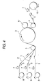
- FIG. 4 An example of the static charge diminution treatment of a work to be wound into a roll is explained by reference to Fig. 4, with respect to a superposition step for thermolaminating an air-permeable supporting member to a porous PTFE membrane.
- Two sheets of an air-permeable supporting member 2 and a porous PTFE membrane 1 are unwound respectively from air-permeable supporting member rolls 8 and a porous PTFE membrane roll 9, and are superposed together by means of directional changes with turning rolls 5.
- the sheet materials superposed are heated while running along the surface of a heating roll 3, and sandwiched between the heating roll 3 and a pinch roll 6. As a result, the sheet materials are united together so that the porous PTFE membrane 1 is interposed between the air-permeable supporting members 2.
- This filtering medium is led by a silicone roll 4 and a turning roll 5 and then wound into a filtering medium roll 10.
- a static charge diminution treatment may be given to at least one work selected from the air-permeable supporting members which have been unwound, the porous PTFE membrane which has been unwound, and the filtering medium which has not been wound.
- a static eliminator 7 is disposed near each of those parts of the sheet materials which have just been unwound respectively from the rolls 8 and roll 9 and of that part of the filtering medium which is located just before the roll 10. Namely, all of the air-permeable supporting members, porous PTFE membrane, and filtering medium are subjected to a static charge diminution treatment.
- the static charge diminution treatment is not particularly limited in method thereof, as long as it can diminish static charges.
- Various static eliminators can be used for the treatment.
- the static charge diminution treatment of either a porous PTFE membrane or a layered product including the membrane is desirably conducted, while preventing sparking, by a method which is not accompanied by local and abrupt movement of static charges built up.
- Examples of such a static charge diminution treatment include treatments in which the work to be treated does not come into contact with any other member.
- a preferred method is to blow ions against the work to be treated.
- Especially preferred is a method in which both cations and anions are blown.
- the surface potential of the work is lowered to 0.3 kV or below, preferably 0.1 kV or below, in terms of absolute value.
- a filtering medium for air filters can be provided which is prevented from suffering the leakage phenomenon (preferably to such a degree that a particle diameter dependence of collection efficiency can be observed in the particle diameter range of from 0.1 to 0.3 ⁇ m).
- the particle diameter dependence cannot be observed in filtering media which have had too large an absolute value of surface potential and hence undergone sparking.
- a sample was attached to a circular holder having an effective area of 100 cm 2 .
- a pressure difference was given between the inlet side and the outlet side to pass air through the sample at a flow rate regulated to 5.3 cm/sec with a flowmeter.
- Polydisperse dioctyl phthalate (DOP) was supplied to the upstream side so that the number of particles having a particle diameter of from 0.1 to 0.2 ⁇ m was 4x10 8 per liter and that of particles having a particle diameter of from 0.2 to 0.3 ⁇ m was 6x10 7 per liter.
- the particle concentration on the upstream side and the concentration of particles which had passed through the sample to the downstream side were measured with a particle counter, and the collection efficiency was determined using the following equation.
- a pasty mixture prepared by compounding a fine PTFE powder with 20 wt% liquid lubricant was preliminarily molded and then formed into a cylindrical rod by paste extrusion. This molding was rolled into a sheet having a thickness of 0.2 mm, and the liquid lubricant was removed therefrom. The sheet was biaxially stretched to obtain a porous PTFE membrane (thickness, 10 ⁇ m; porosity, 93%; average pore diameter, 1.0 ⁇ m; average fiber diameter, 0.2 ⁇ m; pressure loss, 18 mmH 2 O; collection efficiency, 99.999%).
- this porous PTFE membrane was bonded to a nonwoven fabric (Eleves TO303WDO, manufactured by Unitika, Ltd.; PET/PE core/sheath nonwoven fabric) by thermolaminating.
- This laminating of the porous PTFE membrane to the nonwoven fabric was conducted so that two layers of the porous PTFE membrane were interposed among three layers of the nonwoven fabric, as in the constitution a section of which is shown in Fig. 1.
- the sheet material was unwound from a roll and was wound into a roll after the given treatment (stretching or laminating) .
- a static eliminator (blowing type static eliminator BLT-1000, manufactured by Kasuga Electric Works Ltd.) was disposed in each of the unwinding region and winding region. Namely, stretching and laminating were conducted while performing a static charge elimination treatment. That static eliminator is based on the technique in which the static charge built up on a work is diminished by blowing cations and anions against it.
- a filtering medium for air filters which had a thickness of 0.35 mm was obtained in the form of a roll comprising 300 laps of the filtering medium.
- the surface potential of the outermost lap of the filtering medium roll was measured and found to be 0.1 kV.
- the filtering medium was unwound from the roll over a length of about 0.5 m by a hand with an insulating glove, and the surface potential of the unwound part was measured and found to be 0.1 kV.
- the filtering medium in the roll form was touched with the bare hand, and the part thus touched was examined for collection efficiency.
- the collection efficiency for particles having a particle diameter range of from 0.1 to 0.2 ⁇ m was 99.999994%, and the downstream side count of particles having a particle diameter range of from 0.2 to 0.3 ⁇ m was 0.
- this filtering medium was ascertained to have a particle diameter dependence.
- the filtering medium obtained in Example 1 was pleated into the shape of consecutive W's with a reciprocating pleating machine, while continuously eliminating the static charge built up thereon using a static eliminator (the same as the aforementioned one) disposed by the filtering medium on the downstream side of the pleating machine.
- a filtering medium for air filters which had been pleated was obtained.
- This filtering medium was stretched out by a hand with an insulating glove, and the surface potential thereof was measured and found to be 0.2 kV. Furthermore, the filtering medium in the stretched state was touched with the bare hand, and the part thus touched was examined for collection efficiency.
- a filtering medium (thickness, 0.35 mm) for air filters was obtained under the same conditions as in Example 1, except that the static-charge elimination with static eliminators in the step of stretching a porous PTFE membrane and in the step of laminating to a nonwoven fabric was omitted.
- this filtering medium which was obtained in the form of a roll consisting of 300 laps of the filtering medium, the outermost lap had a surface potential of 45 kV.
- This filtering medium was unwound from the roll over a length of about 0.5 m by a hand with an insulating glove. This unwound part of the filtering medium was found to have a surface potential of 0.4 kV.
- the filtering medium in the roll form was touched with the bare hand, and the part thus touched was examined for collection efficiency.
- the collection efficiency for particles having a particle diameter range of from 0.1 to 0.2 ⁇ m was 99.99984% and the collection efficiency for particles having a particle diameter range of from 0.2 to 0.3 ⁇ m was 99.999922%. No particle diameter dependence was observed in this filtering medium.
- the filtering medium obtained in Example 1 was pleated into the shape of consecutive W's with a reciprocating pleating machine. In this pleating, the static charge elimination with static eliminators was omitted.
- This filtering medium was stretched out by a hand with an insulating glove, and the surface potential thereof was measured and found to be -0.5 kV. Furthermore, the pleated filtering medium in the stretched state was touched with the bare hand, and the part thus touched was examined for collection efficiency. As a result, the collection efficiency for particles having a particle diameter range of from 0.1 to 0.2 ⁇ m was 99.99928% and the collection efficiency for particles having a particle diameter range of from 0.2 to 0.3 ⁇ m was 99.99974%. No particle diameter dependence was observed in this filtering medium.
- filtering media obtained in the Examples in which static charges had been diminished, were prevented from suffering the leakage phenomenon even when touched with the bare hand, unlike the filtering media obtained in the Comparative Examples.
- filtering media which had a collection efficiency of 99.99994% or higher with respect to particles having a particle diameter range of from 0.1 to 0.2 ⁇ m and had a particle diameter dependence of collection efficiency in a particle diameter range of from 0.1 to 0.3 ⁇ m could be produced in the Examples.
- the leakage phenomenon observed in filtering media for air filter use employing a porous PTFE membrane can be inhibited.
- an improved product yield and stabilized quality can be attained.
Landscapes
- Chemical & Material Sciences (AREA)
- Chemical Kinetics & Catalysis (AREA)
- Separation Using Semi-Permeable Membranes (AREA)
- Filtering Materials (AREA)
- Laminated Bodies (AREA)
Abstract
Description
| Condition | Criteria for Judgement |
| X ≥ 99.99994% | Downstream side particle count ≤ 5 (particle diameter range: 0.2-0.3 µm) |
| X < 99.99994% | (1 - X/100) ≥ (1 - Y/100)x10 |
Claims (9)
- A filtering medium for air filters, comprising a laminate which comprises at least one porous polytetrafluoroethylene membrane and at least one air-permeable supporting member, the filtering medium having a surface potential of 0.3 kV or lower in terms of absolute value.
- The filtering medium for air filters of claim 1, which has been folded into the shape of consecutive W's.
- The filtering medium for air filters of claim 1, which has been wound into a roll and in which the outermost lap of the roll has a surface potential of 0.3 kV or lower in terms of absolute value.
- A process for producing a filtering medium for air filters, which comprises a step of producing a laminate comprising at least one porous polytetrafluoroethylene membrane and at least one air-permeable supporting member, and a step of diminishing the static charge built up on at least one member selected from the group consisting of the laminate and the materials constituting the laminate.
- The process for producing a filtering medium for air filters of claim 4, which further includes a step of folding the laminate into the shape of consecutive W's, and in which a step of static charge diminution is applied at least to the laminate which has been folded.
- The process for producing a filtering medium for air filters of claim 4, wherein the static charge is diminished by blowing ions.
- The process for producing a filtering medium for air filters of claim 5, wherein the static charge is diminished by blowing ions.
- A process for producing a filtering medium for air filters, comprising a laminate which comprises at least one porous polytetrafluoroethylene membrane and at least one air-permeable supporting member, wherein at least one treatment selected from the stretching of a polytetrafluoroethylene molding for obtaining the porous polytetrafluoroethylene membrane and the superposition of materials for constituting the laminate is conducted in a series of steps comprising unwinding a roll-form work to be treated, treating the unwound work, and winding the work into a roll after the treatment, while diminishing the static charge built up on the work, to thereby successively wind the work which has undergone the treatment and is in a charge diminished state.
- The process for producing a filtering medium for air filters of claim 8, wherein the static charge is diminished by blowing ions.
Applications Claiming Priority (2)
| Application Number | Priority Date | Filing Date | Title |
|---|---|---|---|
| JP2001076395A JP5051944B2 (en) | 2001-03-16 | 2001-03-16 | Filter material for air filter and manufacturing method thereof |
| JP2001076395 | 2001-03-16 |
Publications (2)
| Publication Number | Publication Date |
|---|---|
| EP1240935A2 true EP1240935A2 (en) | 2002-09-18 |
| EP1240935A3 EP1240935A3 (en) | 2002-12-18 |
Family
ID=18933335
Family Applications (1)
| Application Number | Title | Priority Date | Filing Date |
|---|---|---|---|
| EP02005132A Withdrawn EP1240935A3 (en) | 2001-03-16 | 2002-03-07 | Filtering medium for air filters and process for producing the same |
Country Status (3)
| Country | Link |
|---|---|
| US (1) | US20020170434A1 (en) |
| EP (1) | EP1240935A3 (en) |
| JP (1) | JP5051944B2 (en) |
Cited By (5)
| Publication number | Priority date | Publication date | Assignee | Title |
|---|---|---|---|---|
| WO2007081245A1 (en) * | 2006-01-12 | 2007-07-19 | Camfil Ab | Cleanable dust filter comprising a zigzag pleated filter pack |
| EP2221096A4 (en) * | 2007-11-14 | 2011-08-31 | Nitto Denko Corp | Filter filtration material, method for producing the same and filter unit |
| WO2012024572A3 (en) * | 2010-08-20 | 2012-06-07 | H.B. Fuller Company | Filter including a hot melt adhesive coated continuous substrate |
| EP3275531A4 (en) * | 2015-05-07 | 2018-07-11 | Nitto Denko Corporation | Filter material and filter unit |
| EP3292906A4 (en) * | 2015-05-07 | 2018-10-17 | Nitto Denko Corporation | Filter material and filter unit |
Families Citing this family (22)
| Publication number | Priority date | Publication date | Assignee | Title |
|---|---|---|---|---|
| JP2002346319A (en) * | 2001-05-21 | 2002-12-03 | Nitto Denko Corp | Inlet filter media for turbine |
| JP2002346320A (en) * | 2001-05-24 | 2002-12-03 | Daikin Ind Ltd | Method for manufacturing filter medium, filter pack and air filter unit |
| JP4387164B2 (en) * | 2003-11-14 | 2009-12-16 | 株式会社堀場製作所 | Filter for collecting and measuring particulate matter and particulate matter sampler using the same |
| WO2006072167A1 (en) * | 2005-01-03 | 2006-07-13 | Questair Technologies Inc. | Method for making parallel passage contactors |
| EP1855780B1 (en) * | 2005-03-07 | 2014-09-17 | Gore Enterprise Holdings, Inc. | Composite filter media |
| EP1878482B1 (en) * | 2005-04-26 | 2011-07-06 | Nitto Denko Corporation | Filter medium, process for producing the same, method of use thereof, and filter unit |
| JP2006346174A (en) * | 2005-06-16 | 2006-12-28 | Nitto Denko Corp | Air filter medium for vacuum cleaner and air filter unit for vacuum cleaner |
| US8673040B2 (en) | 2008-06-13 | 2014-03-18 | Donaldson Company, Inc. | Filter construction for use with air in-take for gas turbine and methods |
| JP4944864B2 (en) * | 2008-11-04 | 2012-06-06 | 日東電工株式会社 | Polytetrafluoroethylene porous membrane, method for producing the same, and waterproof air-permeable filter |
| US20100186595A1 (en) * | 2009-01-23 | 2010-07-29 | Kang Na Hsiung Enterprise Co., Ltd. | Composite filter and gas filter assembly including the same |
| KR101129169B1 (en) * | 2009-11-25 | 2012-03-26 | 코리아에어텍 주식회사 | Filter for fan type cooling apparatus and filter assembly having the same |
| JP5012990B2 (en) * | 2010-06-17 | 2012-08-29 | ダイキン工業株式会社 | Filter medium provided with porous membrane, manufacturing method thereof, filter pack, and filter unit |
| US20120186452A1 (en) * | 2011-01-26 | 2012-07-26 | Alan Smithies | Multiple Layer HEPA Filter and Method of Manufacture |
| DE102011015981A1 (en) * | 2011-04-04 | 2013-05-16 | Mann + Hummel Gmbh | Ventilation device of a housing and method for producing such |
| JP5839547B2 (en) * | 2011-07-28 | 2016-01-06 | 日東電工株式会社 | Filter filter medium pleating method and pleating apparatus |
| CN104028109A (en) * | 2014-06-27 | 2014-09-10 | 湖州森诺氟材料科技有限公司 | Ceramic filtering pipe with biaxial PTFE (Polytetrafluoroethylene) stretched film and preparation method of pipe |
| US10343095B2 (en) | 2014-12-19 | 2019-07-09 | Hollingsworth & Vose Company | Filter media comprising a pre-filter layer |
| USD829009S1 (en) | 2015-05-15 | 2018-09-25 | Molo Design, Ltd. | Flexible furniture |
| USD794344S1 (en) * | 2015-05-15 | 2017-08-15 | Molo Design, Ltd. | Flexible furniture |
| JP6017654B2 (en) * | 2015-09-14 | 2016-11-02 | 日東電工株式会社 | Filter filter medium pleating method and pleating apparatus |
| JP6920042B2 (en) * | 2016-09-30 | 2021-08-18 | 日東電工株式会社 | Air filter filter media, air filter pack and air filter unit |
| US12654116B2 (en) * | 2025-09-19 | 2026-06-16 | Guangli Wang | Composite filter body |
Family Cites Families (19)
| Publication number | Priority date | Publication date | Assignee | Title |
|---|---|---|---|---|
| US3757164A (en) * | 1970-07-17 | 1973-09-04 | Minnesota Mining & Mfg | Neutralizing device |
| JPS56176017U (en) * | 1980-05-29 | 1981-12-25 | ||
| AU2244683A (en) * | 1983-05-03 | 1984-11-08 | W.L. Gore & Associates, Inc. | Breathable static electrically conductive laminate |
| AU2244783A (en) * | 1983-05-03 | 1984-11-08 | W.L. Gore & Associates, Inc. | Breathable electrically conductive fabric |
| JPS6244410A (en) * | 1985-08-23 | 1987-02-26 | Hitachi Tokyo Electron Co Ltd | Removing method of scrap resin and device |
| DE8816817U1 (en) * | 1988-06-01 | 1990-08-30 | Faudi Feinbau Gmbh, 6370 Oberursel | Filter element for filter/water separator |
| JP2887392B2 (en) * | 1988-12-31 | 1999-04-26 | 鐘淵化学工業株式会社 | Corona discharge treatment method for resin film |
| EP0564553B1 (en) * | 1990-12-26 | 1995-02-22 | Eastman Kodak Company | Method and system for electrostatically discharging a web |
| US5213882A (en) * | 1991-12-18 | 1993-05-25 | W. L. Gore & Associates, Inc. | Static dissipative nonwoven textile material |
| JP2941122B2 (en) * | 1992-07-24 | 1999-08-25 | 信越化学工業株式会社 | Roll film rewinding device |
| US5527569A (en) * | 1994-08-22 | 1996-06-18 | W. L. Gore & Associates, Inc. | Conductive filter laminate |
| JP3079921B2 (en) * | 1994-11-28 | 2000-08-21 | 松下電器産業株式会社 | Solder ball mounting device and mounting method |
| JPH08266827A (en) * | 1995-01-31 | 1996-10-15 | Kureha Chem Ind Co Ltd | Dust filter |
| JP3720421B2 (en) * | 1995-09-05 | 2005-11-30 | 三機工業株式会社 | Static elimination method |
| JP3605482B2 (en) * | 1996-09-02 | 2004-12-22 | 日本無機株式会社 | Processing method of air filter medium having polytetrafluoroethylene membrane |
| TW371284B (en) * | 1996-12-04 | 1999-10-01 | Daikin Ind Ltd | Filtration material of filter and air cleaning device using the filtration material |
| JP2000061224A (en) * | 1998-06-08 | 2000-02-29 | Daikin Ind Ltd | Filter media and bag filter for dust collector of high temperature furnace |
| JP2000325760A (en) * | 1999-05-18 | 2000-11-28 | Toyobo Co Ltd | Non-electrifiable selectively separating membrane |
| DE60001085T2 (en) * | 1999-06-17 | 2003-09-25 | Toray Industries, Inc. | plastic film |
-
2001
- 2001-03-16 JP JP2001076395A patent/JP5051944B2/en not_active Expired - Lifetime
-
2002
- 2002-03-07 EP EP02005132A patent/EP1240935A3/en not_active Withdrawn
- 2002-03-15 US US10/097,972 patent/US20020170434A1/en not_active Abandoned
Cited By (8)
| Publication number | Priority date | Publication date | Assignee | Title |
|---|---|---|---|---|
| WO2007081245A1 (en) * | 2006-01-12 | 2007-07-19 | Camfil Ab | Cleanable dust filter comprising a zigzag pleated filter pack |
| US7883572B2 (en) | 2006-01-12 | 2011-02-08 | Camfil Ab | Cleanable dust filter comprising a zigzag pleated filter pack |
| EP2221096A4 (en) * | 2007-11-14 | 2011-08-31 | Nitto Denko Corp | Filter filtration material, method for producing the same and filter unit |
| US8900351B2 (en) | 2007-11-14 | 2014-12-02 | Nitto Denko Corporation | Filter medium and method of manufacturing the same and filter unit |
| WO2012024572A3 (en) * | 2010-08-20 | 2012-06-07 | H.B. Fuller Company | Filter including a hot melt adhesive coated continuous substrate |
| EP3275531A4 (en) * | 2015-05-07 | 2018-07-11 | Nitto Denko Corporation | Filter material and filter unit |
| EP3292906A4 (en) * | 2015-05-07 | 2018-10-17 | Nitto Denko Corporation | Filter material and filter unit |
| US10688432B2 (en) | 2015-05-07 | 2020-06-23 | Nitto Denko Corporation | Filter medium and filter unit |
Also Published As
| Publication number | Publication date |
|---|---|
| US20020170434A1 (en) | 2002-11-21 |
| JP2002273126A (en) | 2002-09-24 |
| JP5051944B2 (en) | 2012-10-17 |
| EP1240935A3 (en) | 2002-12-18 |
Similar Documents
| Publication | Publication Date | Title |
|---|---|---|
| US20020170434A1 (en) | Filtering medium for air filter and process for producing the same | |
| EP0707033B1 (en) | Composite porous polytetrafluoroethylene membrane | |
| EP1266681B1 (en) | Filter medium for turbine and methods of using and producing the same | |
| CN100503000C (en) | Filter medium, filter unit and air filter unit using the filter medium, and method for producing the filter medium | |
| KR100517888B1 (en) | Filter medium and air filter unit using the same | |
| US6682576B1 (en) | Air filter medium, process of producing filter medium, air filter pack for air filters, and air filter unit for air filters | |
| EP0970739A1 (en) | Filter medium for air filters | |
| EP3520873B1 (en) | Air filter medium, air filter pack, and air filter unit | |
| EP3520874B1 (en) | Air filter medium, air filter pack, and air filter unit | |
| EP3292906B1 (en) | Filter material and filter unit | |
| JP2001170461A (en) | Air filter medium, air filter pack and air filter unit using the same, and method for manufacturing air filter medium | |
| KR102255737B1 (en) | Method for producing air filter material, air filter material, and air filter pack | |
| CN103547351B (en) | Method for forming pleats in filtering member and device for forming pleats | |
| WO2019059382A1 (en) | Filter medium for air filter, filter pleat pack, and air filter unit | |
| EP3275531B1 (en) | Filter material and filter unit | |
| EP3804832A1 (en) | Filter medium and filter unit including same | |
| JP2002301321A (en) | Filter medium, filter pack and air filter unit using the same, and method of manufacturing filter medium | |
| EP1260261A1 (en) | Turbine air filter media | |
| EP4218983A1 (en) | Air filter filtering medium, filter pleat pack, and air filter unit | |
| US12440794B2 (en) | Air filter medium, filter pleat pack, and air filter unit | |
| EP4218982A1 (en) | Air filter filtration member, filter pleat pack, and air filter unit | |
| EP2652189B1 (en) | Fine fiber filter media and processes | |
| EP3903902A1 (en) | Filter pleat pack and air filter unit | |
| EP3903903A1 (en) | Filter pleat pack and air filter unit | |
| EP3812026A1 (en) | Filter medium and filter unit provided with same |
Legal Events
| Date | Code | Title | Description |
|---|---|---|---|
| PUAI | Public reference made under article 153(3) epc to a published international application that has entered the european phase |
Free format text: ORIGINAL CODE: 0009012 |
|
| AK | Designated contracting states |
Kind code of ref document: A2 Designated state(s): AT BE CH CY DE DK ES FI FR GB GR IE IT LI LU MC NL PT SE TR |
|
| AX | Request for extension of the european patent |
Free format text: AL;LT;LV;MK;RO;SI |
|
| PUAL | Search report despatched |
Free format text: ORIGINAL CODE: 0009013 |
|
| RIC1 | Information provided on ipc code assigned before grant |
Free format text: 7B 01D 46/00 A, 7B 01D 46/52 B, 7B 01D 39/16 B, 7B 01D 29/21 B |
|
| AK | Designated contracting states |
Kind code of ref document: A3 Designated state(s): AT BE CH CY DE DK ES FI FR GB GR IE IT LI LU MC NL PT SE TR |
|
| AX | Request for extension of the european patent |
Free format text: AL;LT;LV;MK;RO;SI |
|
| 17P | Request for examination filed |
Effective date: 20030210 |
|
| AKX | Designation fees paid |
Designated state(s): CH DE FR GB LI SE |
|
| 17Q | First examination report despatched |
Effective date: 20040809 |
|
| STAA | Information on the status of an ep patent application or granted ep patent |
Free format text: STATUS: THE APPLICATION IS DEEMED TO BE WITHDRAWN |
|
| 18D | Application deemed to be withdrawn |
Effective date: 20050211 |