EP1240913A2 - Pen-type injector for liquid medicine - Google Patents
Pen-type injector for liquid medicine Download PDFInfo
- Publication number
- EP1240913A2 EP1240913A2 EP02005278A EP02005278A EP1240913A2 EP 1240913 A2 EP1240913 A2 EP 1240913A2 EP 02005278 A EP02005278 A EP 02005278A EP 02005278 A EP02005278 A EP 02005278A EP 1240913 A2 EP1240913 A2 EP 1240913A2
- Authority
- EP
- European Patent Office
- Prior art keywords
- plunger
- housing
- starting point
- switch
- liquid medicine
- Prior art date
- Legal status (The legal status is an assumption and is not a legal conclusion. Google has not performed a legal analysis and makes no representation as to the accuracy of the status listed.)
- Granted
Links
Images




Classifications
-
- A—HUMAN NECESSITIES
- A61—MEDICAL OR VETERINARY SCIENCE; HYGIENE
- A61M—DEVICES FOR INTRODUCING MEDIA INTO, OR ONTO, THE BODY; DEVICES FOR TRANSDUCING BODY MEDIA OR FOR TAKING MEDIA FROM THE BODY; DEVICES FOR PRODUCING OR ENDING SLEEP OR STUPOR
- A61M5/00—Devices for bringing media into the body in a subcutaneous, intra-vascular or intramuscular way; Accessories therefor, e.g. filling or cleaning devices, arm rests
- A61M5/14—Infusion devices, e.g. infusing by gravity; Blood infusion; Accessories therefor
- A61M5/142—Pressure infusion, e.g. using pumps
- A61M5/145—Pressure infusion, e.g. using pumps using pressurised reservoirs, e.g. by means of pistons
- A61M5/1452—Pressure infusion, e.g. using pumps using pressurised reservoirs, e.g. by means of pistons pressurised by means of pistons
- A61M5/14566—Pressure infusion, e.g. using pumps using pressurised reservoirs, e.g. by means of pistons pressurised by means of pistons with a replaceable reservoir for receiving a piston rod of the pump
-
- A—HUMAN NECESSITIES
- A61—MEDICAL OR VETERINARY SCIENCE; HYGIENE
- A61M—DEVICES FOR INTRODUCING MEDIA INTO, OR ONTO, THE BODY; DEVICES FOR TRANSDUCING BODY MEDIA OR FOR TAKING MEDIA FROM THE BODY; DEVICES FOR PRODUCING OR ENDING SLEEP OR STUPOR
- A61M5/00—Devices for bringing media into the body in a subcutaneous, intra-vascular or intramuscular way; Accessories therefor, e.g. filling or cleaning devices, arm rests
- A61M5/178—Syringes
- A61M5/20—Automatic syringes, e.g. with automatically actuated piston rod, with automatic needle injection, filling automatically
-
- A—HUMAN NECESSITIES
- A61—MEDICAL OR VETERINARY SCIENCE; HYGIENE
- A61M—DEVICES FOR INTRODUCING MEDIA INTO, OR ONTO, THE BODY; DEVICES FOR TRANSDUCING BODY MEDIA OR FOR TAKING MEDIA FROM THE BODY; DEVICES FOR PRODUCING OR ENDING SLEEP OR STUPOR
- A61M5/00—Devices for bringing media into the body in a subcutaneous, intra-vascular or intramuscular way; Accessories therefor, e.g. filling or cleaning devices, arm rests
- A61M5/178—Syringes
- A61M5/31—Details
- A61M5/315—Pistons; Piston-rods; Guiding, blocking or restricting the movement of the rod or piston; Appliances on the rod for facilitating dosing ; Dosing mechanisms
- A61M5/31533—Dosing mechanisms, i.e. setting a dose
- A61M5/31545—Setting modes for dosing
- A61M5/31546—Electrically operated dose setting, e.g. input via touch screen or plus/minus buttons
-
- A—HUMAN NECESSITIES
- A61—MEDICAL OR VETERINARY SCIENCE; HYGIENE
- A61P—SPECIFIC THERAPEUTIC ACTIVITY OF CHEMICAL COMPOUNDS OR MEDICINAL PREPARATIONS
- A61P19/00—Drugs for skeletal disorders
- A61P19/08—Drugs for skeletal disorders for bone diseases, e.g. rachitism, Paget's disease
-
- A—HUMAN NECESSITIES
- A61—MEDICAL OR VETERINARY SCIENCE; HYGIENE
- A61P—SPECIFIC THERAPEUTIC ACTIVITY OF CHEMICAL COMPOUNDS OR MEDICINAL PREPARATIONS
- A61P7/00—Drugs for disorders of the blood or the extracellular fluid
- A61P7/04—Antihaemorrhagics; Procoagulants; Haemostatic agents; Antifibrinolytic agents
-
- A—HUMAN NECESSITIES
- A61—MEDICAL OR VETERINARY SCIENCE; HYGIENE
- A61M—DEVICES FOR INTRODUCING MEDIA INTO, OR ONTO, THE BODY; DEVICES FOR TRANSDUCING BODY MEDIA OR FOR TAKING MEDIA FROM THE BODY; DEVICES FOR PRODUCING OR ENDING SLEEP OR STUPOR
- A61M5/00—Devices for bringing media into the body in a subcutaneous, intra-vascular or intramuscular way; Accessories therefor, e.g. filling or cleaning devices, arm rests
- A61M5/178—Syringes
- A61M5/31—Details
- A61M5/315—Pistons; Piston-rods; Guiding, blocking or restricting the movement of the rod or piston; Appliances on the rod for facilitating dosing ; Dosing mechanisms
- A61M5/31565—Administration mechanisms, i.e. constructional features, modes of administering a dose
- A61M5/31576—Constructional features; Drive mechanisms or modes for piston rods
- A61M2005/31588—Constructional features; Drive mechanisms or modes for piston rods electrically driven
-
- A—HUMAN NECESSITIES
- A61—MEDICAL OR VETERINARY SCIENCE; HYGIENE
- A61M—DEVICES FOR INTRODUCING MEDIA INTO, OR ONTO, THE BODY; DEVICES FOR TRANSDUCING BODY MEDIA OR FOR TAKING MEDIA FROM THE BODY; DEVICES FOR PRODUCING OR ENDING SLEEP OR STUPOR
- A61M2205/00—General characteristics of the apparatus
- A61M2205/16—General characteristics of the apparatus with back-up system in case of failure
-
- A—HUMAN NECESSITIES
- A61—MEDICAL OR VETERINARY SCIENCE; HYGIENE
- A61M—DEVICES FOR INTRODUCING MEDIA INTO, OR ONTO, THE BODY; DEVICES FOR TRANSDUCING BODY MEDIA OR FOR TAKING MEDIA FROM THE BODY; DEVICES FOR PRODUCING OR ENDING SLEEP OR STUPOR
- A61M2205/00—General characteristics of the apparatus
- A61M2205/18—General characteristics of the apparatus with alarm
-
- A—HUMAN NECESSITIES
- A61—MEDICAL OR VETERINARY SCIENCE; HYGIENE
- A61M—DEVICES FOR INTRODUCING MEDIA INTO, OR ONTO, THE BODY; DEVICES FOR TRANSDUCING BODY MEDIA OR FOR TAKING MEDIA FROM THE BODY; DEVICES FOR PRODUCING OR ENDING SLEEP OR STUPOR
- A61M2205/00—General characteristics of the apparatus
- A61M2205/35—Communication
-
- A—HUMAN NECESSITIES
- A61—MEDICAL OR VETERINARY SCIENCE; HYGIENE
- A61M—DEVICES FOR INTRODUCING MEDIA INTO, OR ONTO, THE BODY; DEVICES FOR TRANSDUCING BODY MEDIA OR FOR TAKING MEDIA FROM THE BODY; DEVICES FOR PRODUCING OR ENDING SLEEP OR STUPOR
- A61M2205/00—General characteristics of the apparatus
- A61M2205/50—General characteristics of the apparatus with microprocessors or computers
-
- A—HUMAN NECESSITIES
- A61—MEDICAL OR VETERINARY SCIENCE; HYGIENE
- A61M—DEVICES FOR INTRODUCING MEDIA INTO, OR ONTO, THE BODY; DEVICES FOR TRANSDUCING BODY MEDIA OR FOR TAKING MEDIA FROM THE BODY; DEVICES FOR PRODUCING OR ENDING SLEEP OR STUPOR
- A61M2205/00—General characteristics of the apparatus
- A61M2205/82—Internal energy supply devices
- A61M2205/8206—Internal energy supply devices battery-operated
-
- A—HUMAN NECESSITIES
- A61—MEDICAL OR VETERINARY SCIENCE; HYGIENE
- A61M—DEVICES FOR INTRODUCING MEDIA INTO, OR ONTO, THE BODY; DEVICES FOR TRANSDUCING BODY MEDIA OR FOR TAKING MEDIA FROM THE BODY; DEVICES FOR PRODUCING OR ENDING SLEEP OR STUPOR
- A61M5/00—Devices for bringing media into the body in a subcutaneous, intra-vascular or intramuscular way; Accessories therefor, e.g. filling or cleaning devices, arm rests
- A61M5/178—Syringes
- A61M5/31—Details
- A61M5/315—Pistons; Piston-rods; Guiding, blocking or restricting the movement of the rod or piston; Appliances on the rod for facilitating dosing ; Dosing mechanisms
- A61M5/31533—Dosing mechanisms, i.e. setting a dose
- A61M5/31535—Means improving security or handling thereof, e.g. blocking means, means preventing insufficient dosing, means allowing correction of overset dose
- A61M5/31541—Means preventing setting of a dose beyond the amount remaining in the cartridge
Definitions
- the present invention relates to a personal injector for liquid medicine. More particularly, the invention relates to a simplified injector for liquid medicine, which is intended for patients who have chronic diseases and require self-administration of liquid medicines, and which enables the user to administer a dose of liquid medicine with ease in safety as well as to perform automatic injection and control of the administration.
- Such a drug injector generally comprises a body provided with a dosage-setting dial, an injection button, a piston and unit-setting indicator; a medicine container holder and a cap.
- the administration of insulin is carried out by a method comprising the steps of inserting a cartridge into a medicine container holder of the body, fitting a needle on a tip of the body, injecting the liquid medicine for air-release and confirmation of fluid communication, and setting a dosage of the liquid medicine.
- the liquid medicine injectors of the conventional pen-type have the following disadvantages: When the cartridge has been emptied, the user may have the false impression that the injector got out of order. The injection of the setting dosage can not be confirmed since the injection of the liquid medicine is carried out only while the injection button is pushed. The given dose can not be quantified accurately since the liquid medicine may drip down when the needle is accidentally taken out from the skin during administration. The correct control of administration can not be performed since the residual liquid medicine content is not expressed numerically.
- the present invention has been made under such circumstances to provide a personal injector for liquid medicine, which makes it possible to automatically and simply perform injection and medication control.
- Another object of the present invention is to provide a personal injector for liquid medicine, which makes it possible to administer a dose of liquid medicine with ease in safety.
- the personal injector for liquid medicine of the present invention is so designed as to be connected to a computer, provided with a limit switch for stopping the forward movement of a push member or a plunger at a forward limit point, wherein the plunger is adapted to be returned to its starting point by reverse drive of a electric motor when the limit switch is turned on.
- a personal injector for liquid medicine comprising:
- the limit switch may be adapted to be turned on.
- the motor may drive the plunger until it reaches to the forward limit point where the limit switch is turned on and a difference between the desired dosage and the actually injected amount of the liquid medicine may be calculated to set it as an additional desired dosage as well as to display it on the display.
- the personal injector may be provided with means for detecting a clogging of a needle attached to the needle-mounting part.
- the housing may be provided with a battery holder for holding a battery to use the battery as a power source.
- the housing may be provided with a connector adapted to be connected to an external power source.
- the housing is preferably provided with a power switch.
- the plunger is provided with a manual dial so that the plunger is manually moved in case of battery shutoff, electric power failure or trouble in the circuit.
- the medicine container holder may be provided with a cartridge detect switch for detecting presence of the cartridge.
- the housing may be provided with a confirmation switch adjacent to the mode select switch for confirmation of the selected operation mode and the starting point sensor being "on".
- the housing may be provided with an alarm which is activated when the needle clogging is detected or when the plunger is returned to the starting point, and which is deactivated when the confirmation switch is pushed.
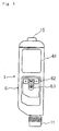
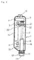
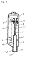
- a personal injector for liquid medicine comprising a housing 1 provided with a needle-mounting part 11, a medicine container holder 12 and a connecting port 13 to a personal computer not illustrated in the drawings; a plunger 2 arranged in the housing 1; an electric motor 3 arranged in the housing for driving the plunger 2; a limit switch 4 for limiting the forward movement of the plunger 2; a starting point sensor 5 for detecting return of the plunger 2 to the starting point; and a substrate 6 provided with a display 61 and a operation mode-select switch 62.
- the plunger 2 is movable between a starting point and a forward limit point.
- the limit switch is arranged at the forward limit point of the plunger 2. If the limit switch 4 is turned on, the motor 3 drives the plunger 2 in the reverse direction to move it to the starting point thereof.
- the housing 1 is a box-shaped member having a distal end and a proximal end and is provided at the distal end thereof with the needle-mounting part 11.
- the housing 1 is further provided with the connecting port 13 to a personal computer at a suitable position thereof.
- the electric motor 3 is arranged in the housing 1 and serves as means for driving the plunger 2.
- the medicine container holder 12 is arranged in the housing 1 adjacent to the needle mounting part 11 and on the distal side thereof.
- the plunger 2 is movably arranged in the housing 1 on the distal side of the medicine container holder 12.
- the needle (not shown) attached to the needle mounting part 11, medicine container holder 12 and plunger 2 are arranged on the same longitudinal axis.
- Numeral 131 designates a cap for connector port to the personal computer
- 141 is a cover for battery case
- 17 is a cover to be opened or closed when operating the movable dial
- 18 is a support used for placing the injector on a desk or optional place.
- a cartridge (not illustrated) is inserted into the medicine container holder 12 through the distal end of the housing 1.
- it may be set in the medicine container holder 12 by opening a cover of the housing 1.
- the injector is of a type wherein a cartridge (one form of a cartridge) is inserted into the medicine container holder from the distal end
- the medicine container holder 12 is formed in the form of a hollow cylinder and partially protruded from the distal end of the housing 1, as illustrated in Figs. 1-4.
- the needle-mounting part 11 is a cap-like member with a through-hole 111 at a top plane thereof and is removably fitted on a protruded portion 121 of the medicine container holder 12 in the proper way such as, for example, screw engagement.
- the needle-mounting part 11 is removed first from the protruded portion 121 of the medicine container holder 12 and screwed again on the protruded portion 121 after inserting the cartridge into the medicine container holder 12.
- the needle-mounting part 11 pushes the cartridge in the medicine container holder 12 at a top plate thereof.
- the through-hole 111 may take any desired size, provided that it is smaller than the diameter of the cartridge but sufficiently greater than an outer diameter of a canula of the needle.
- the housing 1 may be provided with a battery holder 14 as illustrated in Figs. 3 and 4 to use a battery as a power source for the injector.
- the housing 1 may be provided with an external power receptacle (not shown) to use the external power source as the power source.
- the housing 1 may be provided with both battery holder 14 and the external power receptacle to use then selectively.
- the injector is so designed as to use any battery, it is preferred to provide a power switch 15 at the proximal end of the housing 1 to save power consumption.
- the plunger 2 is a hollow cylindrical member having an internal thread 23 and a flanged portion 22 provided at the proximal end thereof. On the proximal end of the flanged portion 22, there is provided a protrusion 221 protruded radially from the flanged portion 22 so as to come into contact with the starting point sensor 5 and limit switch 4.
- the plunger 2 is screw-mounted on a ball screw 8 and adapted to be driven by the motor 3. By activating the motor 8, a rotatory motion thereof is converted into the rotatory motion of the ball screw 8, which is then converted into a longitudinal linear motion of the plunger 2 engaged at the internal thread 23 thereof with the ball screw 8. Thus, the plunger 2 is moved forward or backward along the longitudinal axis of the ball screw 8.
- the proximal end 22 of the plunger 2 may be provided with a manual dial 21 to allow the user to manually drive the plunger 2 in case of unexpected situations such as battery shutoff, electric power failure or trouble in the circuit.
- the plunger 2 is driven by the motor 3 from the starting point where the protrusion 221 comes into contact with the starting point sensor 5 to the forward limit point where the protrusion 221 comes into contact with the limit switch 4, or vice versa.
- the limit switch 4 When the limit switch 4 is turned on, the motor 3 drives the ball screw 8 in the reverse direction until the plunger 2 is returned back to the starting point.
- the limit switch 4 is positioned at the forward limit point for the plunger 2 and turned on when the protrusion 221 comes into contact therewith or when a desired dosage is greater than the residual liquid medicine content in the cartridge and the operation mode has been set to a non-additional dosage mode.
- the starting point sensor 5 is positioned at the starting point and turned on to stop the backward movement of the plunger 2 when the plunger 2 is returned to the starting point and comes into contact with the starting point sensor 5 at the protrusion 221 thereof.
- a micro switch or a software switch generally constitutes the limit switch 4. It is preferred to use a micro switch and a software switch together.
- a micro switch generally constitutes the starting point sensor 5.
- the injector is provided with means for detecting any clogging of the needle attached to the needle-mounting part 11, to avoid any trouble of the motor 3 resulting from the clogging of the needle.
- Means for detecting any clogging of the needle comprises a strain gauge 7 arranged between the motor 3 and the housing 1 to detect a small strain occurred in the motor 3.
- Another means for detecting any clogging of the needle comprises means for detecting the revolution of the motor or a moving velocity of the plunger 2. In this case, the clogging of the needle is detected by comparing a normal value of the revolution of the motor or a moving velocity of the plunger 2 to an actual revolution or moving velocity measured during operation of the injector.
- the needle is determined as being clogged up.
- Another means for detecting any clogging of the needle comprises a load cell attached to the plunger 2 to detect a stress from the plunger 2. In this case, the needle is determined as being clogged up when the stress exceeds a certain set value.
- needle used herein includes needles having a tube, such as winged catheters.
- the medicine container holder 12 is provided with a container-detecting switch 16 which is turned on by setting the medicine container in the medicine container holder 12 to allow the motor 3 to be activated only when the cartridge is set correctly in the medicine container holder 12.
- the substrate 6 has a display 61, a mode-select switch 62 and a control unit (not shown) mounted thereon.
- the mode select switch 62 is adapted to allow the user to set a desired dosage, medication records, the kind of alarm (sounds, flashing caution signal, etc.), loudness level or length of sound (when the alarm is set to sound), need for additional dosage and the like.
- the display 61 is adapted to display the time for next administration, a residual volume of liquid medicine, an additional dosage and other necessary information in addition to the operation mode set by the mode-select switch 62.
- the information or data except for those set by the mode select switch 62 are input by a personal computer electrically connected to the injector through the connecting port 13.
- the substrate 6 may be provided with a confirmation switch 63 adjacent to the mode select switch 62 to confirm on-state of the starting point sensor, set mode of the injector, notice of administration and the like. This enables to prevent erroneous use of the injector.
- the housing 1 may be provided with an alarm (not shown) which is activated at the time of detection of the clogging of the needle, or at the time of return to the stating point of the plunger 2, and deactivated by pushing the confirmation switch 63.
- the alarm may be constituted by one element selected from the group consisting of light emitting diodes for flashing caution signal, buzzers and chimes.
- the injector may be provided with all of these alarms to allow the user to optionally select one or more of these elements.
- the control system includes a microprocessor (MPU) adapted to control the alarm (ALM), display 61 through a display control circuit 611 and motor 3 through a motor control circuit 31.
- the microprocessor MPU is adapted to receive and process information sent from the power switch 15, confirmatory information sent from the confirmation switch 63, mode select information sent from mode select switch 62, information sent from the limit switch 4 and starting point sensor 5, information sent from the clogging-detect means 7, and control information sent from the motor control circuit.
- the additional amount of the medicine is calculated by MPU, determined and displayed as a difference between a desired dosage and an actual dosage of the medicine.
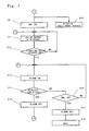
- the control system When turning on the power switch 15, the control system is activated and is ready to accept an information, as illustrated in Fig. 6.
- the microprocessor MPU gives notice to the user by alarm and, if necessary, displays message on the screen of the display 61 (step 2).
- the notice of administration is held for a certain period, for example, 5 to 10 seconds.
- the MPU By pushing the confirmation switch 63 (step 3), the MPU displays relationship between a desired dosage and a residual liquid medicine content of the cartridge. If the desired dosage is equal to or smaller than the residual content (step 4), the motor 4 is activated to perform injection of the medicine (step 6).
- step 8 After completing injection of the desired dosage of the medicine (step 8), the operation of MPU varies with the conditions of the injector. If the desired dosage is judged at step 4 as being smaller than the residual content, MPU activates the alarm (step 13) as illustrated in Fig. 7. By pushing the confirmation switch 63, the MPU stops the alarm (step 17) and terminates the operation for administration of the liquid medicine.
- the plunger 2 reaches to the forward limit point and turns on the limit switch 4 (step 9), whereby completing the administration of the desired dosage of the liquid medicine.
- the MPU displays an additional dosage on the screen of the display 63 as being zero (step 10) and activates the motor 4 in reverse (step 11).
- the plunger 2 is moved backward and returned to the starting point.
- the starting point sensor 5 is turned on by the plunger 2 (step 12) and the alarm is activated by MPU (step 13).
- the alarm is stopped (step 15 or step 17), thereby completing the operation of administration.
- the user is requested to push a mode switch (M) of the mode select switch 62 to display an additional dosage mode on the screen of the display 61.
- M mode switch
- the motor 3 is activated to start administration of the liquid medicine.
- the plunger 2 reaches the forward limit point and turns on the limit switch 4 (step 7).
- the MPU displays the additional dosage on the screen of the display 63 as illustrated in Fig.
- step 7 activates the motor 4 in reverse (step 11).
- the plunger 2 is moved backward and returned to the starting point.
- the starting point sensor 5 is turned on (step 12) and the alarm is activated by MPU (step 13).
- the alarm is stopped (step 15).
- the confirmation switch 63 step 3
- the administration of additional dosage is started in the same manner as mentioned above for the case where the desired dosage is judged as being smaller than the residual content.
- step 5 If the minus-signed switch is pushed (step 5), the limit switch 4 is turned on (step 9) and the motor 4 is driven in reverse (step 11), as illustrated in Fig. 7. Thus, the plunger 2 is moved backward and returned to the starting point. At this point, the starting point sensor 5 is turned on (step 12) and the alarm is activated by MPU (step 13). By replacing the consumed cartridge with new one (step 14), the alarm is stopped (step 15). By pushing the confirmation switch 63 (step 3), the administration of the desired dosage is started in the same manner as mentioned above for the case where the desired dosage is judged as being smaller than the residual content.
- the personal injector of the present invention makes it possible to automatically and simply perform injection and medication control. Further, the personal injector of the present invention makes it possible to administer a dose of liquid medicine with ease in safety by provision of clogging-detect means and the manual operating dial.
Landscapes
- Health & Medical Sciences (AREA)
- Life Sciences & Earth Sciences (AREA)
- Engineering & Computer Science (AREA)
- Veterinary Medicine (AREA)
- Public Health (AREA)
- General Health & Medical Sciences (AREA)
- Animal Behavior & Ethology (AREA)
- Hematology (AREA)
- Anesthesiology (AREA)
- Vascular Medicine (AREA)
- Heart & Thoracic Surgery (AREA)
- Biomedical Technology (AREA)
- General Chemical & Material Sciences (AREA)
- Nuclear Medicine, Radiotherapy & Molecular Imaging (AREA)
- Chemical Kinetics & Catalysis (AREA)
- Chemical & Material Sciences (AREA)
- Medicinal Chemistry (AREA)
- Bioinformatics & Cheminformatics (AREA)
- Pharmacology & Pharmacy (AREA)
- Organic Chemistry (AREA)
- Physical Education & Sports Medicine (AREA)
- Diabetes (AREA)
- Orthopedic Medicine & Surgery (AREA)
- Rheumatology (AREA)
- Infusion, Injection, And Reservoir Apparatuses (AREA)
Abstract
Description
Claims (8)
- A personal injector for liquid medicine comprising:wherein said plunger is adapted to be moved to the starting point by the reverse driving of the motor when said limit switch is turned on.a housing having a distal end and a proximal end and including a needle-mounting part, a medicine container holder, and a connecting port to a computer;a plunger arranged in said housing and adapted to be longitudinally moved, by said motor, between a starting point and a forward limit point within the housing;an electric motor for driving said plunger;a limit switch arranged at the forward limit point to stop the forward movement of said plunger;a starting point sensor for detecting return of the plunger to the starting point; anda substrate arranged in said housing and provided with a display and mode-select switch;
- The personal injector according to claim 1,
wherein said limit switch is turned on in case that a desired dosage is greater than a residual liquid medicine content. - The personal injector according to claim 1 or 2,
wherein said motor is driven to move the plunger to a forward limit point where the limit switch is turned on, in case that a desired dosage is greater than a residual liquid medicine content and an operation mode is set to a additional dosage mode, whereby calculating a difference between the desired dosage of the liquid medicine and an actual dosage of the liquid medicine to determine an additional desired dosage as well as to display the same. - The personal injector according to any of claims 1 to 3,
wherein said injector is adapted to detect clogging of a needle attached to the needle-mounting part. - The personal injector according to any of claims 1 to 4,
wherein said housing is provided with a battery holder for holding a battery and with a power switch. - The personal injector according to any of claims 1 to 5,
wherein said housing is provided with a connector for a power source. - The personal injector according to any of claims 1 to 6,
wherein said plunger is provided with a manual dial which allows the user to manually move the plunger forward. - The personal injector according to any of claims 1 to 7,
wherein said medicine container holder is provided with a medicine container detect switch for detecting presence of the medicine container.
Priority Applications (1)
| Application Number | Priority Date | Filing Date | Title |
|---|---|---|---|
| DK02005278T DK1240913T3 (en) | 2001-03-15 | 2002-03-11 | Pen-type injection device for liquid medicine |
Applications Claiming Priority (2)
| Application Number | Priority Date | Filing Date | Title |
|---|---|---|---|
| JP2001073883 | 2001-03-15 | ||
| JP2001073883A JP3845857B2 (en) | 2001-03-15 | 2001-03-15 | Simple chemical injector |
Publications (3)
| Publication Number | Publication Date |
|---|---|
| EP1240913A2 true EP1240913A2 (en) | 2002-09-18 |
| EP1240913A3 EP1240913A3 (en) | 2002-12-11 |
| EP1240913B1 EP1240913B1 (en) | 2004-12-01 |
Family
ID=18931248
Family Applications (1)
| Application Number | Title | Priority Date | Filing Date |
|---|---|---|---|
| EP02005278A Expired - Lifetime EP1240913B1 (en) | 2001-03-15 | 2002-03-11 | Pen-type injector for liquid medicine |
Country Status (5)
| Country | Link |
|---|---|
| US (1) | US6913591B2 (en) |
| EP (1) | EP1240913B1 (en) |
| JP (1) | JP3845857B2 (en) |
| DE (1) | DE60202088T2 (en) |
| DK (1) | DK1240913T3 (en) |
Cited By (20)
| Publication number | Priority date | Publication date | Assignee | Title |
|---|---|---|---|---|
| WO2004052429A1 (en) * | 2002-12-10 | 2004-06-24 | Zi Medical Plc | A syringe driver assembly |
| FR2856929A1 (en) * | 2003-07-03 | 2005-01-07 | Olivetti S N C Di Olivetti E F | Syringe for injecting a predetermined volume of liquid, useful in veterinary medicine and for injection of cadavers, includes an electromechanical device for controlling advance of the piston |
| EP1759727A1 (en) * | 2005-09-02 | 2007-03-07 | F.Hoffmann-La Roche Ag | Infusion device having a control unit |
| EP2060284A1 (en) * | 2007-11-13 | 2009-05-20 | F.Hoffmann-La Roche Ag | Medical injection device having data input means and a pivotable display |
| EP1877662A4 (en) * | 2005-04-13 | 2009-09-23 | Therasense Inc | INSULIN DISPENSING PUMP WITH SHAPE MEMORY AND VARIABLE VOLUME |
| WO2010066746A1 (en) | 2008-12-11 | 2010-06-17 | Sanofi-Aventis Deutschland Gmbh | Medical delivery device |
| EP2351590A3 (en) * | 2010-01-29 | 2012-11-07 | Nippon Shika Yakuhin KK. | Computer controlled electric syringe |
| US8496988B2 (en) | 2002-11-11 | 2013-07-30 | Lg Display Co., Ltd. | Dispenser for fabricating liquid crystal display panel and method for controlling gap between nozzle and substrate by using the same |
| CN103656782A (en) * | 2012-09-21 | 2014-03-26 | 上海微创生命科技有限公司 | Method and device for monitoring infusion of insulin pen |
| WO2015129940A1 (en) * | 2014-02-28 | 2015-09-03 | 최규동 | Device and method for injecting drug |
| EP2902051A4 (en) * | 2012-09-26 | 2016-05-25 | Terumo Corp | SYRINGE PUMP |
| CN105771038A (en) * | 2016-03-17 | 2016-07-20 | 南京医科大学第附属医院 | Accurate trace-amount acupoint injection pen |
| WO2017147039A1 (en) * | 2016-02-26 | 2017-08-31 | Eli Lilly And Company | Reusable medication delivery device with remaining medication determination capability |
| WO2018086817A1 (en) * | 2016-11-09 | 2018-05-17 | Sanofi-Aventis Deutschland Gmbh | Injector device |
| US10857304B2 (en) | 2016-03-25 | 2020-12-08 | Eli Lilly And Company | Determination of a dose set and delivered in a medication delivery device |
| US11266788B2 (en) | 2016-04-19 | 2022-03-08 | Eli Lilly And Company | Determination of a dose in a medication delivery device using two moving arrays with teeth and a sensor |
| US11452819B2 (en) | 2016-12-15 | 2022-09-27 | Eli Lilly And Company | Medication delivery device with sensing system |
| US11471607B2 (en) | 2016-08-12 | 2022-10-18 | Eli Lilly And Company | Dose sensing mechanism in a medication delivery device |
| US11571516B2 (en) | 2016-06-06 | 2023-02-07 | E3D Agricultural Cooperative Association | Multiple use computerized injector |
| US11872375B2 (en) | 2012-09-05 | 2024-01-16 | E3D Agricultural Cooperative Association Ltd. | Electronic auto-injection device |
Families Citing this family (61)
| Publication number | Priority date | Publication date | Assignee | Title |
|---|---|---|---|---|
| JP4633094B2 (en) * | 2001-12-13 | 2011-02-16 | パナソニック株式会社 | Medical dosing device |
| US7727181B2 (en) | 2002-10-09 | 2010-06-01 | Abbott Diabetes Care Inc. | Fluid delivery device with autocalibration |
| US20060079842A1 (en) * | 2004-10-13 | 2006-04-13 | Liebel-Flarsheim Company | Powerhead control in a power injection system |
| EP1690560A1 (en) * | 2005-02-14 | 2006-08-16 | Ares Trading S.A. | Medication delivery device |
| EP1690559A1 (en) * | 2005-02-14 | 2006-08-16 | Ares Trading S.A. | Medication delivery device |
| DE102007002096A1 (en) * | 2007-01-09 | 2008-07-10 | B. Braun Melsungen Ag | Device for injecting liquids |
| EP3689274A1 (en) | 2007-02-05 | 2020-08-05 | Boston Scientific Limited | Thrombectomy system |
| JP5275601B2 (en) * | 2007-09-21 | 2013-08-28 | 株式会社根本杏林堂 | Chemical injection device and medical imaging system |
| US9974904B2 (en) * | 2008-05-20 | 2018-05-22 | Avant Medical Corp. | Autoinjector system |
| US8052645B2 (en) | 2008-07-23 | 2011-11-08 | Avant Medical Corp. | System and method for an injection using a syringe needle |
| US9510854B2 (en) | 2008-10-13 | 2016-12-06 | Boston Scientific Scimed, Inc. | Thrombectomy catheter with control box having pressure/vacuum valve for synchronous aspiration and fluid irrigation |
| HUE035598T2 (en) | 2008-12-02 | 2018-05-28 | Allergan Inc | Injection device |
| JP5666560B2 (en) * | 2009-04-30 | 2015-02-12 | サノフィ−アベンティス・ドイチュラント・ゲゼルシャフト・ミット・ベシュレンクテル・ハフツング | Pen syringe with ergonomic button arrangement |
| WO2011032961A1 (en) * | 2009-09-18 | 2011-03-24 | Sanofi-Aventis Deutschland Gmbh | Latching and control unit for integration in a medical device |
| EP2575936A1 (en) * | 2010-06-07 | 2013-04-10 | Sanofi-Aventis Deutschland GmbH | Drug delivery device with light source |
| LT2699293T (en) | 2011-04-20 | 2019-04-25 | Amgen Inc. | Autoinjector apparatus |
| WO2012160160A1 (en) * | 2011-05-25 | 2012-11-29 | Sanofi-Aventis Deutschland Gmbh | Medicament delivery device with dispense interface sensor and method controlling the device |
| CN106267472B (en) * | 2011-07-15 | 2019-08-30 | 赛诺菲-安万特德国有限公司 | Drug delivery device with electromechanical drive mechanism |
| JP5432307B2 (en) * | 2012-03-21 | 2014-03-05 | 株式会社根本杏林堂 | Chemical injection device |
| USD898908S1 (en) | 2012-04-20 | 2020-10-13 | Amgen Inc. | Pharmaceutical product cassette for an injection device |
| US10293110B2 (en) * | 2012-11-22 | 2019-05-21 | Phc Holdings Corporation | Pharmaceutical injection device, method for controlling pharmaceutical injection device, program, and recording medium |
| US10492990B2 (en) | 2013-03-15 | 2019-12-03 | Amgen Inc. | Drug cassette, autoinjector, and autoinjector system |
| US20140350518A1 (en) | 2013-05-23 | 2014-11-27 | Allergan, Inc. | Syringe extrusion accessory |
| US9433427B2 (en) | 2014-04-08 | 2016-09-06 | Incuvate, Llc | Systems and methods for management of thrombosis |
| US9248221B2 (en) | 2014-04-08 | 2016-02-02 | Incuvate, Llc | Aspiration monitoring system and method |
| GB201407680D0 (en) * | 2014-05-01 | 2014-06-18 | New Injection Systems Ltd | Indicator |
| US10029048B2 (en) * | 2014-05-13 | 2018-07-24 | Allergan, Inc. | High force injection devices |
| US9883877B2 (en) | 2014-05-19 | 2018-02-06 | Walk Vascular, Llc | Systems and methods for removal of blood and thrombotic material |
| US10564129B2 (en) * | 2014-08-08 | 2020-02-18 | Sanofi-Aventis Deutschland Gmbh | Method and arrangement for acoustically testing the mechanical integrity of a cartridge |
| US10226585B2 (en) | 2014-10-01 | 2019-03-12 | Allergan, Inc. | Devices for injection and dosing |
| US12154453B2 (en) * | 2014-10-03 | 2024-11-26 | Noble International, Llc | Medicament training device and system |
| WO2016132937A1 (en) * | 2015-02-20 | 2016-08-25 | テルモ株式会社 | Liquid drug administration device |
| KR20170136522A (en) | 2015-03-10 | 2017-12-11 | 알러간 파마슈티컬스 홀딩스 (아일랜드) 언리미티드 컴파니 | Multi Needle Injector |
| CN112545886A (en) | 2015-03-10 | 2021-03-26 | 里珍纳龙药品有限公司 | Sterile piercing systems and methods |
| US9744297B2 (en) * | 2015-04-10 | 2017-08-29 | Medimop Medical Projects Ltd. | Needle cannula position as an input to operational control of an injection device |
| US10702292B2 (en) | 2015-08-28 | 2020-07-07 | Incuvate, Llc | Aspiration monitoring system and method |
| US10561440B2 (en) | 2015-09-03 | 2020-02-18 | Vesatek, Llc | Systems and methods for manipulating medical devices |
| US20170100142A1 (en) | 2015-10-09 | 2017-04-13 | Incuvate, Llc | Systems and methods for management of thrombosis |
| US10226263B2 (en) | 2015-12-23 | 2019-03-12 | Incuvate, Llc | Aspiration monitoring system and method |
| EP3199188A1 (en) | 2016-01-29 | 2017-08-02 | Carebay Europe Ltd. | Electrical information device for communicating information related to a medicament delivery |
| US10492805B2 (en) | 2016-04-06 | 2019-12-03 | Walk Vascular, Llc | Systems and methods for thrombolysis and delivery of an agent |
| KR102288170B1 (en) | 2016-04-08 | 2021-08-09 | 알레간 인코포레이티드 | Aspiration and injection device |
| CN113577438B (en) | 2016-08-01 | 2023-05-23 | 西医药服务以色列有限公司 | Partial door closing prevention spring |
| CN115177808A (en) * | 2017-02-08 | 2022-10-14 | 株式会社根本杏林堂 | Injection device, actuator, and method for manufacturing injection device |
| USD867582S1 (en) | 2017-03-24 | 2019-11-19 | Allergan, Inc. | Syringe device |
| CA3055583A1 (en) | 2017-05-05 | 2018-11-08 | Regeneron Pharmaceuticals, Inc. | Auto-injector |
| WO2018222521A1 (en) | 2017-05-30 | 2018-12-06 | West Pharma. Services IL, Ltd. | Modular drive train for wearable injector |
| JP2018126493A (en) * | 2017-10-20 | 2018-08-16 | 株式会社根本杏林堂 | Injection device, actuator and production method of injection device |
| EP3740266A4 (en) | 2018-01-19 | 2021-10-13 | Birya Biotech, Inc. | TOOL FOR THE MAINTENANCE OF A AUTO-INJECTOR |
| US11678905B2 (en) | 2018-07-19 | 2023-06-20 | Walk Vascular, Llc | Systems and methods for removal of blood and thrombotic material |
| JP1631197S (en) * | 2018-09-27 | 2019-05-13 | Syringe | |
| JP1633704S (en) * | 2018-11-05 | 2019-06-10 | Syringe | |
| KR102564963B1 (en) * | 2020-09-07 | 2023-08-09 | 이오플로우(주) | Apparatus for Infusing medical liquid |
| US12518655B2 (en) * | 2020-10-05 | 2026-01-06 | Noble International, Llc | Medicament training device and system |
| EP4267213A1 (en) | 2020-12-23 | 2023-11-01 | Relavo, Inc. | System and method for injection and retraction of fluid |
| US12274458B2 (en) | 2021-02-15 | 2025-04-15 | Walk Vascular, Llc | Systems and methods for removal of blood and thrombotic material |
| JP2024506374A (en) | 2021-02-15 | 2024-02-13 | ウォーク バスキュラー, エルエルシー | System and method for removing blood and thrombotic material |
| USD1007676S1 (en) | 2021-11-16 | 2023-12-12 | Regeneron Pharmaceuticals, Inc. | Wearable autoinjector |
| WO2024059794A1 (en) * | 2022-09-16 | 2024-03-21 | Cvrx, Inc. | System, devices, and methods for guidewire delivery |
| CN115887822B (en) * | 2022-11-02 | 2025-05-13 | 中国人民解放军海军第九七一医院 | A portable intramuscular injector |
| WO2024259313A1 (en) | 2023-06-16 | 2024-12-19 | Regeneron Pharamceuticals, Inc. | Medical device packaging and related methods |
Family Cites Families (8)
| Publication number | Priority date | Publication date | Assignee | Title |
|---|---|---|---|---|
| NL8701091A (en) * | 1987-05-08 | 1988-12-01 | Spruyt Hillen Bv | INJECTION PEN. |
| DE3833821A1 (en) * | 1988-10-05 | 1990-04-12 | Braun Melsungen Ag | INJECTION DEVICE |
| US5322511A (en) * | 1992-04-21 | 1994-06-21 | Sterling Winthrop Inc. | Portable hand-held power injector |
| CA2129284C (en) * | 1993-11-24 | 1999-03-09 | Kenneth J. Niehoff | Controlling plunger drives for fluid injection in animals |
| US5536249A (en) * | 1994-03-09 | 1996-07-16 | Visionary Medical Products, Inc. | Pen-type injector with a microprocessor and blood characteristic monitor |
| US5690618A (en) * | 1995-02-22 | 1997-11-25 | Mark Timothy Smith | Electronic syringe |
| IL127586A0 (en) * | 1996-07-05 | 1999-10-28 | Novo Nordisk As | Dose setting device |
| JP3288943B2 (en) * | 1996-12-06 | 2002-06-04 | スーガン株式会社 | Medical injector head |
-
2001
- 2001-03-15 JP JP2001073883A patent/JP3845857B2/en not_active Expired - Fee Related
-
2002
- 2002-03-11 DE DE60202088T patent/DE60202088T2/en not_active Expired - Fee Related
- 2002-03-11 DK DK02005278T patent/DK1240913T3/en active
- 2002-03-11 EP EP02005278A patent/EP1240913B1/en not_active Expired - Lifetime
- 2002-03-13 US US10/095,713 patent/US6913591B2/en not_active Expired - Fee Related
Cited By (33)
| Publication number | Priority date | Publication date | Assignee | Title |
|---|---|---|---|---|
| US8496988B2 (en) | 2002-11-11 | 2013-07-30 | Lg Display Co., Ltd. | Dispenser for fabricating liquid crystal display panel and method for controlling gap between nozzle and substrate by using the same |
| WO2004052429A1 (en) * | 2002-12-10 | 2004-06-24 | Zi Medical Plc | A syringe driver assembly |
| FR2856929A1 (en) * | 2003-07-03 | 2005-01-07 | Olivetti S N C Di Olivetti E F | Syringe for injecting a predetermined volume of liquid, useful in veterinary medicine and for injection of cadavers, includes an electromechanical device for controlling advance of the piston |
| EP1877662A4 (en) * | 2005-04-13 | 2009-09-23 | Therasense Inc | INSULIN DISPENSING PUMP WITH SHAPE MEMORY AND VARIABLE VOLUME |
| EP1759727A1 (en) * | 2005-09-02 | 2007-03-07 | F.Hoffmann-La Roche Ag | Infusion device having a control unit |
| EP2060284A1 (en) * | 2007-11-13 | 2009-05-20 | F.Hoffmann-La Roche Ag | Medical injection device having data input means and a pivotable display |
| WO2009062675A1 (en) * | 2007-11-13 | 2009-05-22 | Roche Diagnostics Gmbh | Medical injection device having data input means and a pivotable display |
| WO2010066746A1 (en) | 2008-12-11 | 2010-06-17 | Sanofi-Aventis Deutschland Gmbh | Medical delivery device |
| US8491522B2 (en) | 2010-01-29 | 2013-07-23 | Nippon Shika Yakuhin Co., Ltd. | Computer controlled electric syringe |
| EP2351590A3 (en) * | 2010-01-29 | 2012-11-07 | Nippon Shika Yakuhin KK. | Computer controlled electric syringe |
| US11872375B2 (en) | 2012-09-05 | 2024-01-16 | E3D Agricultural Cooperative Association Ltd. | Electronic auto-injection device |
| CN103656782A (en) * | 2012-09-21 | 2014-03-26 | 上海微创生命科技有限公司 | Method and device for monitoring infusion of insulin pen |
| CN103656782B (en) * | 2012-09-21 | 2016-04-13 | 上海微创生命科技有限公司 | For monitoring the method and apparatus of the infusion of novopen |
| EP2902051A4 (en) * | 2012-09-26 | 2016-05-25 | Terumo Corp | SYRINGE PUMP |
| WO2015129940A1 (en) * | 2014-02-28 | 2015-09-03 | 최규동 | Device and method for injecting drug |
| CN105848696A (en) * | 2014-02-28 | 2016-08-10 | 崔奎东 | Device and method for injecting drug |
| WO2017147039A1 (en) * | 2016-02-26 | 2017-08-31 | Eli Lilly And Company | Reusable medication delivery device with remaining medication determination capability |
| EP4338772A3 (en) * | 2016-02-26 | 2024-05-15 | Eli Lilly and Company | Reusable medication delivery device with remaining medication determination capability |
| CN108697856A (en) * | 2016-02-26 | 2018-10-23 | 伊莱利利公司 | The reusable medicine delivery device of ability is measured with left drug |
| CN108697856B (en) * | 2016-02-26 | 2021-04-06 | 伊莱利利公司 | Reusable drug delivery device with residual drug determination capability |
| AU2017222360B2 (en) * | 2016-02-26 | 2019-08-08 | Eli Lilly And Company | Reusable medication delivery device with remaining medication determination capability |
| US10722658B2 (en) | 2016-02-26 | 2020-07-28 | Eli Lilly And Company | Reusable medication delivery device with remaining medication determination capability |
| CN105771038A (en) * | 2016-03-17 | 2016-07-20 | 南京医科大学第附属医院 | Accurate trace-amount acupoint injection pen |
| US10857304B2 (en) | 2016-03-25 | 2020-12-08 | Eli Lilly And Company | Determination of a dose set and delivered in a medication delivery device |
| US11266788B2 (en) | 2016-04-19 | 2022-03-08 | Eli Lilly And Company | Determination of a dose in a medication delivery device using two moving arrays with teeth and a sensor |
| US11571516B2 (en) | 2016-06-06 | 2023-02-07 | E3D Agricultural Cooperative Association | Multiple use computerized injector |
| US11471607B2 (en) | 2016-08-12 | 2022-10-18 | Eli Lilly And Company | Dose sensing mechanism in a medication delivery device |
| US12350477B2 (en) | 2016-08-12 | 2025-07-08 | Eli Lilly And Company | Dose sensing mechanism in a medication delivery device |
| CN109922850A (en) * | 2016-11-09 | 2019-06-21 | 赛诺菲-安万特德国有限公司 | Syringe device |
| WO2018086817A1 (en) * | 2016-11-09 | 2018-05-17 | Sanofi-Aventis Deutschland Gmbh | Injector device |
| EP4649976A3 (en) * | 2016-11-09 | 2026-01-21 | Sanofi-Aventis Deutschland GmbH | Injector device |
| US11452819B2 (en) | 2016-12-15 | 2022-09-27 | Eli Lilly And Company | Medication delivery device with sensing system |
| US12059557B2 (en) | 2016-12-15 | 2024-08-13 | Eli Lilly And Company | Medication delivery device with sensing system |
Also Published As
| Publication number | Publication date |
|---|---|
| US20020133114A1 (en) | 2002-09-19 |
| JP2002272839A (en) | 2002-09-24 |
| JP3845857B2 (en) | 2006-11-15 |
| US6913591B2 (en) | 2005-07-05 |
| DE60202088D1 (en) | 2005-01-05 |
| EP1240913A3 (en) | 2002-12-11 |
| DK1240913T3 (en) | 2005-04-04 |
| DE60202088T2 (en) | 2005-12-01 |
| EP1240913B1 (en) | 2004-12-01 |
Similar Documents
| Publication | Publication Date | Title |
|---|---|---|
| EP1240913B1 (en) | Pen-type injector for liquid medicine | |
| US12322504B2 (en) | Device and method for detecting an actuation action performable with a medical device | |
| US11197963B2 (en) | Device for attachment to an injection device | |
| US7981102B2 (en) | Removable controller for an infusion pump | |
| US7892199B2 (en) | Occlusion sensing for an infusion pump | |
| US9731072B2 (en) | Infusion pump system | |
| CN1602212B (en) | medical drug delivery device | |
| EP2767297B1 (en) | Drug delivery management systems | |
| US7833196B2 (en) | Illumination instrument for an infusion pump | |
| EP2162166B1 (en) | Infusion pump system with contamination-resistant features | |
| US20190160224A1 (en) | Infusion Pump System and Method | |
| JP2009520570A (en) | Needleless injection device | |
| JP2020192365A (en) | Reusable medication delivery device with remaining medication determination capability | |
| HK1201223B (en) | Drug delivery management systems | |
| HK1164763B (en) | Drug delivery system |
Legal Events
| Date | Code | Title | Description |
|---|---|---|---|
| PUAI | Public reference made under article 153(3) epc to a published international application that has entered the european phase |
Free format text: ORIGINAL CODE: 0009012 |
|
| AK | Designated contracting states |
Kind code of ref document: A2 Designated state(s): AT BE CH CY DE DK ES FI FR GB GR IE IT LI LU MC NL PT SE TR |
|
| AX | Request for extension of the european patent |
Free format text: AL;LT;LV;MK;RO;SI |
|
| PUAL | Search report despatched |
Free format text: ORIGINAL CODE: 0009013 |
|
| AK | Designated contracting states |
Kind code of ref document: A3 Designated state(s): AT BE CH CY DE DK ES FI FR GB GR IE IT LI LU MC NL PT SE TR |
|
| AX | Request for extension of the european patent |
Free format text: AL;LT;LV;MK;RO;SI |
|
| RIC1 | Information provided on ipc code assigned before grant |
Free format text: 7A 61M 5/145 A, 7A 61M 5/315 B, 7A 61M 5/24 B, 7A 61M 5/20 B |
|
| 17P | Request for examination filed |
Effective date: 20030515 |
|
| 17Q | First examination report despatched |
Effective date: 20030715 |
|
| AKX | Designation fees paid |
Designated state(s): DE DK FR GB IT |
|
| GRAP | Despatch of communication of intention to grant a patent |
Free format text: ORIGINAL CODE: EPIDOSNIGR1 |
|
| GRAS | Grant fee paid |
Free format text: ORIGINAL CODE: EPIDOSNIGR3 |
|
| GRAA | (expected) grant |
Free format text: ORIGINAL CODE: 0009210 |
|
| AK | Designated contracting states |
Kind code of ref document: B1 Designated state(s): DE DK FR GB IT |
|
| REG | Reference to a national code |
Ref country code: GB Ref legal event code: FG4D |
|
| REG | Reference to a national code |
Ref country code: IE Ref legal event code: FG4D |
|
| REF | Corresponds to: |
Ref document number: 60202088 Country of ref document: DE Date of ref document: 20050105 Kind code of ref document: P |
|
| REG | Reference to a national code |
Ref country code: DK Ref legal event code: T3 |
|
| ET | Fr: translation filed | ||
| PLBE | No opposition filed within time limit |
Free format text: ORIGINAL CODE: 0009261 |
|
| STAA | Information on the status of an ep patent application or granted ep patent |
Free format text: STATUS: NO OPPOSITION FILED WITHIN TIME LIMIT |
|
| 26N | No opposition filed |
Effective date: 20050902 |
|
| PGFP | Annual fee paid to national office [announced via postgrant information from national office to epo] |
Ref country code: DK Payment date: 20090313 Year of fee payment: 8 |
|
| PGFP | Annual fee paid to national office [announced via postgrant information from national office to epo] |
Ref country code: GB Payment date: 20090311 Year of fee payment: 8 |
|
| PGFP | Annual fee paid to national office [announced via postgrant information from national office to epo] |
Ref country code: DE Payment date: 20090306 Year of fee payment: 8 Ref country code: IT Payment date: 20090317 Year of fee payment: 8 |
|
| PGFP | Annual fee paid to national office [announced via postgrant information from national office to epo] |
Ref country code: FR Payment date: 20090316 Year of fee payment: 8 |
|
| REG | Reference to a national code |
Ref country code: DK Ref legal event code: EBP |
|
| GBPC | Gb: european patent ceased through non-payment of renewal fee |
Effective date: 20100311 |
|
| REG | Reference to a national code |
Ref country code: FR Ref legal event code: ST Effective date: 20101130 |
|
| PG25 | Lapsed in a contracting state [announced via postgrant information from national office to epo] |
Ref country code: FR Free format text: LAPSE BECAUSE OF NON-PAYMENT OF DUE FEES Effective date: 20100331 |
|
| PG25 | Lapsed in a contracting state [announced via postgrant information from national office to epo] |
Ref country code: DE Free format text: LAPSE BECAUSE OF NON-PAYMENT OF DUE FEES Effective date: 20101001 |
|
| PG25 | Lapsed in a contracting state [announced via postgrant information from national office to epo] |
Ref country code: GB Free format text: LAPSE BECAUSE OF NON-PAYMENT OF DUE FEES Effective date: 20100311 Ref country code: IT Free format text: LAPSE BECAUSE OF NON-PAYMENT OF DUE FEES Effective date: 20100311 |
|
| PG25 | Lapsed in a contracting state [announced via postgrant information from national office to epo] |
Ref country code: DK Free format text: LAPSE BECAUSE OF NON-PAYMENT OF DUE FEES Effective date: 20100331 |