EP1239899B1 - Medizinisches gerät aus ultrahochmolekularem polyolefin - Google Patents
Medizinisches gerät aus ultrahochmolekularem polyolefin Download PDFInfo
- Publication number
- EP1239899B1 EP1239899B1 EP00988110A EP00988110A EP1239899B1 EP 1239899 B1 EP1239899 B1 EP 1239899B1 EP 00988110 A EP00988110 A EP 00988110A EP 00988110 A EP00988110 A EP 00988110A EP 1239899 B1 EP1239899 B1 EP 1239899B1
- Authority
- EP
- European Patent Office
- Prior art keywords
- balloon
- polyolefin
- molecular weight
- ultrahigh molecular
- polyethylene
- Prior art date
- Legal status (The legal status is an assumption and is not a legal conclusion. Google has not performed a legal analysis and makes no representation as to the accuracy of the status listed.)
- Expired - Lifetime
Links
Images

Classifications
-
- A—HUMAN NECESSITIES
- A61—MEDICAL OR VETERINARY SCIENCE; HYGIENE
- A61L—METHODS OR APPARATUS FOR STERILISING MATERIALS OR OBJECTS IN GENERAL; DISINFECTION, STERILISATION OR DEODORISATION OF AIR; CHEMICAL ASPECTS OF BANDAGES, DRESSINGS, ABSORBENT PADS OR SURGICAL ARTICLES; MATERIALS FOR BANDAGES, DRESSINGS, ABSORBENT PADS OR SURGICAL ARTICLES
- A61L27/00—Materials for grafts or prostheses or for coating grafts or prostheses
- A61L27/14—Macromolecular materials
- A61L27/16—Macromolecular materials obtained by reactions only involving carbon-to-carbon unsaturated bonds
-
- A—HUMAN NECESSITIES
- A61—MEDICAL OR VETERINARY SCIENCE; HYGIENE
- A61L—METHODS OR APPARATUS FOR STERILISING MATERIALS OR OBJECTS IN GENERAL; DISINFECTION, STERILISATION OR DEODORISATION OF AIR; CHEMICAL ASPECTS OF BANDAGES, DRESSINGS, ABSORBENT PADS OR SURGICAL ARTICLES; MATERIALS FOR BANDAGES, DRESSINGS, ABSORBENT PADS OR SURGICAL ARTICLES
- A61L29/00—Materials for catheters, medical tubing, cannulae, or endoscopes or for coating catheters
- A61L29/04—Macromolecular materials
- A61L29/041—Macromolecular materials obtained by reactions only involving carbon-to-carbon unsaturated bonds
-
- C—CHEMISTRY; METALLURGY
- C08—ORGANIC MACROMOLECULAR COMPOUNDS; THEIR PREPARATION OR CHEMICAL WORKING-UP; COMPOSITIONS BASED THEREON
- C08L—COMPOSITIONS OF MACROMOLECULAR COMPOUNDS
- C08L2207/00—Properties characterising the ingredient of the composition
- C08L2207/06—Properties of polyethylene
- C08L2207/068—Ultra high molecular weight polyethylene
-
- C—CHEMISTRY; METALLURGY
- C08—ORGANIC MACROMOLECULAR COMPOUNDS; THEIR PREPARATION OR CHEMICAL WORKING-UP; COMPOSITIONS BASED THEREON
- C08L—COMPOSITIONS OF MACROMOLECULAR COMPOUNDS
- C08L23/00—Compositions of homopolymers or copolymers of unsaturated aliphatic hydrocarbons having only one carbon-to-carbon double bond; Compositions of derivatives of such polymers
- C08L23/02—Compositions of homopolymers or copolymers of unsaturated aliphatic hydrocarbons having only one carbon-to-carbon double bond; Compositions of derivatives of such polymers not modified by chemical after-treatment
- C08L23/04—Homopolymers or copolymers of ethene
- C08L23/06—Polyethylene
-
- Y—GENERAL TAGGING OF NEW TECHNOLOGICAL DEVELOPMENTS; GENERAL TAGGING OF CROSS-SECTIONAL TECHNOLOGIES SPANNING OVER SEVERAL SECTIONS OF THE IPC; TECHNICAL SUBJECTS COVERED BY FORMER USPC CROSS-REFERENCE ART COLLECTIONS [XRACs] AND DIGESTS
- Y10—TECHNICAL SUBJECTS COVERED BY FORMER USPC
- Y10T—TECHNICAL SUBJECTS COVERED BY FORMER US CLASSIFICATION
- Y10T156/00—Adhesive bonding and miscellaneous chemical manufacture
- Y10T156/10—Methods of surface bonding and/or assembly therefor
- Y10T156/1002—Methods of surface bonding and/or assembly therefor with permanent bending or reshaping or surface deformation of self sustaining lamina
- Y10T156/1036—Bending of one piece blank and joining edges to form article
- Y10T156/1038—Hollow cylinder article
-
- Y—GENERAL TAGGING OF NEW TECHNOLOGICAL DEVELOPMENTS; GENERAL TAGGING OF CROSS-SECTIONAL TECHNOLOGIES SPANNING OVER SEVERAL SECTIONS OF THE IPC; TECHNICAL SUBJECTS COVERED BY FORMER USPC CROSS-REFERENCE ART COLLECTIONS [XRACs] AND DIGESTS
- Y10—TECHNICAL SUBJECTS COVERED BY FORMER USPC
- Y10T—TECHNICAL SUBJECTS COVERED BY FORMER US CLASSIFICATION
- Y10T428/00—Stock material or miscellaneous articles
- Y10T428/13—Hollow or container type article [e.g., tube, vase, etc.]
- Y10T428/1352—Polymer or resin containing [i.e., natural or synthetic]
-
- Y—GENERAL TAGGING OF NEW TECHNOLOGICAL DEVELOPMENTS; GENERAL TAGGING OF CROSS-SECTIONAL TECHNOLOGIES SPANNING OVER SEVERAL SECTIONS OF THE IPC; TECHNICAL SUBJECTS COVERED BY FORMER USPC CROSS-REFERENCE ART COLLECTIONS [XRACs] AND DIGESTS
- Y10—TECHNICAL SUBJECTS COVERED BY FORMER USPC
- Y10T—TECHNICAL SUBJECTS COVERED BY FORMER US CLASSIFICATION
- Y10T428/00—Stock material or miscellaneous articles
- Y10T428/13—Hollow or container type article [e.g., tube, vase, etc.]
- Y10T428/1352—Polymer or resin containing [i.e., natural or synthetic]
- Y10T428/139—Open-ended, self-supporting conduit, cylinder, or tube-type article
Definitions
- This invention generally relates to medical devices, and particularly to balloon catheters, stent covers, and vascular grafts.
- a guiding catheter In percutaneous transluminal coronary angioplasty (PTCA) procedures, a guiding catheter is advanced until the distal tip of the guiding catheter is seated in the ostium of a desired coronary artery.
- a guidewire positioned within an inner lumen of an dilatation catheter, is first advanced out of the distal end of the guiding catheter into the patient's coronary artery until the distal end of the guidewire crosses a lesion to be dilated. Then the dilatation catheter having an inflatable balloon on the distal portion thereof is advanced into the patient's coronary anatomy, over the previously introduced guidewire, until the balloon of the dilatation catheter is properly positioned across the lesion.
- the dilatation balloon is inflated with liquid one or more times to a predetermined size at relatively high pressures (e.g. greater than 8 atmospheres) so that the stenosis is compressed against the arterial wall and the wall expanded to open up the passageway.
- relatively high pressures e.g. greater than 8 atmospheres
- the inflated diameter of the balloon is approximately the same diameter as the native diameter of the body lumen being dilated so as to complete the dilatation but not overexpand the artery wall.
- Substantial, uncontrolled expansion of the balloon against the vessel wall can cause trauma to the vessel wall.
- blood flow resumes through the dilated artery and the dilatation catheter can be removed therefrom.
- angioplasty procedures there may be restenosis of the artery, i.e. reformation of the arterial blockage, which necessitates either another angioplasty procedure, or some other method of repairing or strengthening the dilated area.
- an intravascular prosthesis generally called a stent
- Stents may also be used to repair vessels having an intimal flap or dissection or to generally strengthen a weakened section of a vessel.
- Stents are usually delivered to a desired location within a coronary artery in a contracted condition on a balloon of a catheter which is similar in many respects to a balloon angioplasty catheter, and expanded to a larger diameter by expansion of the balloon.
- the balloon is deflated to remove the catheter and the stent left in place within the artery at the site of the dilated lesion.
- Stent covers on an inner or an outer surface of the stent have been used in, for example, the treatment of pseudo-aneurysms and perforated arteries, and to prevent prolapse of plaque.
- vascular grafts comprising cylindrical tubes made from tissue or synthetic materials such as DACRON may be implanted in vessels to strengthen or repair the vessel, or used in an anastomosis procedure to connect vessels segments together.
- Angioplasty balloons preferably have high strength for inflation at relatively high pressure, and high flexibility and softness for improved ability to track the tortuous anatomy and cross lesions in the uninflated state.
- the balloon compliance is chosen so that the balloon will have a desired amount of expansion during inflation.
- Compliant balloons for example balloons made from materials such as polyethylene, exhibit substantial stretching upon application of internal pressure.
- intravascular catheter balloons should be substantially noncompliant once expanded to a working diameter.
- catheter balloons should also be formed from relatively strong materials in order to withstand the pressures necessary for various procedures without failing.
- such characteristics require the use of a material that does not stretch appreciably, which consequently necessitates that the balloon material be folded around the catheter shaft prior to inflation.
- Such designs may be used for formed-in-place angioplasty balloons and stent delivery balloons.
- Prior art formed-in-place balloons have suffered from problems such as insufficient strength, poor control over expansion, and significantly complicated processing during catheter manufacturing.
- This invention is directed to medical devices, and particularly intracorporeal devices for therapeutic or diagnostic uses, having at least a component formed of ultrahigh molecular weight polyolefin (UHMW polyolefin) which has a node and fibril microstructure comprising nodes interconnected by fibrils.
- UHMW polyolefin ultrahigh molecular weight polyolefin
- the UHMW polyolefin is an ultrahigh molecular weight polyethylene (UHMW polyethylene).
- UHMW polyethylene ultrahigh molecular weight polyethylene
- a presently preferred embodiment is directed to UHMW polyolefin which is microporous.
- One embodiment of the invention comprises an expandable member such as a balloon for an intraluminal catheter, formed at least in part of the UHMW polyolefin, such as UHMW polyethylene.
- a stent delivery system comprising a balloon catheter and a stent mounted on the balloon has a component, such as the catheter balloon or a stent cover, which is formed at least in part of the UHMW polyolefin, such as UHMW polyethylene.
- Another embodiment of the invention comprises a vascular graft formed at least in part of the UHMW polyolefin, such as UHMW polyethylene.
- vascular graft should be understood to include grafts and endoluminal prostheses, such as those surgically attached to vessels, as for example in vascular bypass or anastomosis, or implanted within vessels, as for example in aneurysm repair or at the site of a balloon angioplasty or stent deployment.
- endoluminal prostheses such as those surgically attached to vessels, as for example in vascular bypass or anastomosis, or implanted within vessels, as for example in aneurysm repair or at the site of a balloon angioplasty or stent deployment.
- UHMW polyethylene Although discussed primarily in terms of UHMW polyethylene, it should be understood that the invention applies as well to UHMW polyolefins in general, and to other materials having a node and fibril microstructure such as polypropylene, nylon, and expanded polytetrafluoroethylene.
- the UHMW polyethylene has a molecular weight which is higher than the molecular weight of high molecular weight polyethylenes, and which is about 2 million to about 10 million grams/mole, preferably about 3 million to about 6 million grams/mole. Unlike high molecular weight polyethylenes, which generally have a molecular weight of about 400,000 to about 600,000 grams/mole, the UHMW polyethylene is difficult to melt process. Balloons formed from this material exhibit compliant expansion at relatively low strains and exhibit substantially less compliance at higher strains.
- the node and fibril structure of the UHMW polyethylene causes it to exhibit essentially compressible deformation at relatively small strains, with a low Young's modulus in tension for the compressed material.
- the UHMW polyethylene balloons of the invention preferably exhibit low compliance due to rearrangement in the microstructure.
- Embodiments of the invention suited to intravascular applications preferably exhibit compliant radial expansion of about 70% to about 450%, and more particularly 100% to about 400%, of the uninflated diameter, at pressures up to about 6 to about 8 atm. Once expanded, the balloons exhibit relatively low compliance at pressures above about 8 atm and can have a burst pressure of at least about 18 atm.
- the UHMW polyethylene exhibits microstructural rearrangement and the balloon exhibits low compliance in the working pressure range with a radial expansion of about 5% to about 20%, and preferably less than about 15% of the uninflated diameter of the balloon, at inflation pressures of about 6 atm to about 18 atm.
- the UHMW polyethylene exhibits a negative Poisson ratio.
- the UHMW polyethylene preferably has a foam-like compressible state at low strains so that the stent can be crimped onto the balloon with good retention.
- One embodiment of the invention is directed to a noninflated balloon comprising ultrahigh molecular weight polyolefin in a compressed configuration having a reduced porosity relative to the ultrahigh molecular weight polyolefin in a noncompressed configuration.
- the balloon formed of UHMW polyolefin such as UHMW polyethylene
- the balloon formed of UHMW polyolefin is compressed in the radial direction of the balloon, to provide a reduced profile medical device component.
- the balloon formed of UHMW polyolefin, such as UHMW polyethylene is compressed in the axial direction of the balloon, to provide reduced axial lengthening during radial expansion of the medical device component formed therefrom.
- the UHMW polyolefin such as UHMW polyethylene
- UHMW polyethylene is compressed before being formed into a balloon, to provide a balloon exhibiting improved stress/strain curve response.
- the UHMW polyolefin compressed before being formed into a balloon is preferably compressed in the direction of the fibrils of the material, i.e., in the direction of the deformation which imparted the node and fibril structure to the material, while the thickness of the material is held constant.
- the UHMW polyolefin is compressed perpendicular or substantially perpendicular to the direction of the fibrils.
- the stress/strain curve response of the compressed UHMW polyolefin is characterized by a sudden increase of stress at increased strain, which allows for the construction of a balloon having desired expansion characteristics with a compliant radial expansion at initial inflation pressures and relatively low compliance at higher inflation pressures.
- the compressed UHMW polyethylene exhibits an improved substantial or compliant expansion upon inflation to an internal pressure within a first pressure range, and substantially less expansion within a second pressure range higher than the first pressure range.
- the compressed material provides a wingless balloon that can provide the desired radial compliance characteristics without excessive balloon length increase or shortening during inflation of the balloon.
- the shape of the stress/strain curve of the resulting compressed UHMW polyethylene material will depend on factors such as porosity of the material before compression, compression conditions, fibril length, node size and node aspect ratio, ram extrusion conditions, material deformation or orientation conditions, heat set conditions, and the balloon construction characteristics such as winding angle.
- the compressed UHMW polyethylene is particularly useful for a stent deploying balloon, due to the lack of wings on the unexpanded balloon. In conventional stent deploying balloons, the folded balloon wings of the unexpanded balloon would unfold during inflation of the balloon, resulting in nonuniform expansion of the stent mounted on the unexpanded balloon.
- Balloon catheters of the invention generally comprise an elongated shaft with at least one lumen and balloon formed of UHMW polyolefin such as UHMW polyethylene on a distal shaft section with an interior in fluid communication with the shaft lumen.
- the balloon catheters of the invention may be configured for a variety of uses, such as angioplasty or stent delivery.
- a stent delivery catheter employs a balloon having the characteristics of the invention to deploy the stent.
- the oriented polyethylene exhibits a foam-like compressible state at low strains, facilitating crimping of the stent onto the balloon with improved stent retention.
- the stent may be provided with a stent cover generally comprising a tubular sheath formed of the UHMW polyethylene and configured to be disposed on an outer and/or inner surface of the stent and implanted with the stent in the patient's vessel.
- Vascular grafts of the invention generally comprise a tubular body formed of the UHMW polyolefin such as UHMW polyethylene.
- the vascular graft is configured to be implanted in a patient, and may be used for a variety of procedures including anastomosis, bypass surgery, implantation within a vessel lumen to reduce restenosis, and aneurysm repair.
- the invention also comprises methods of forming a medical device component such as a balloon, stent cover or vascular graft, from microporous polyolefin such as polyethylene having an oriented node and fibril structure.
- the method comprises the steps of compacting ultrahigh molecular weight polyethylene powder into a billet, deforming the compacted polyethylene to render the polyethylene microporous and to impart an oriented node and fibril structure to the polyethylene, and forming the medical device component from the polyethylene.
- the powder can be sintered prior to deformation.
- the oriented polyethylene can be heat set.
- a tubular medical device component such as a balloon may be formed by wrapping a film or sheet of the oriented polyethylene around a mandrel to form a tube and then heat fusing the polyethylene layers together, or by directly producing an oriented tubular member.
- the medical devices such as catheter balloons, stent covers, and vascular grafts of the invention have improved performance due to the UHMW polyolefin such as UHMW polyethylene which is microporous, biocompatible, and biostable, and which has excellent mechanical properties.
- UHMW polyethylene is more resistant to electron-beam (i.e., e-beam) degradation than expanded polytetrafluoroethylene (i.e., ePTFE) which degrades when exposed to e-beams, making e-beam sterilization more of an option than with ePTFE.
- Medical devices such as balloons of this invention can be expanded compliantly to their working diameter but exhibit substantially less compliance at greater pressures, providing control over expansion even at pressures suitable for conventional intravascular procedures such as angioplasty or stent delivery. Further, the formed-in-place balloons of the invention have sufficient strength to provide desired safety to conventional intravascular procedures.
- UHMW polyethylene also facilitates device manufacture, because the processing temperatures for polyethylene are relatively low, and the polyethylene can be readily attached with adhesives or heat bonded using tie layers to other device components. Thus, bonding to other device components is easier than with ePTFE.
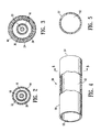
- FIGs. 1-3 illustrate an over-the-wire type stent delivery balloon catheter 10 embodying features of the invention.
- Catheter 10 generally comprises an elongated catheter shaft 12 having an outer tubular member 14 and an inner tubular member 16.
- Inner tubular member 14 defines a guidewire lumen 18 adapted to slidingly receive a guidewire 20.
- the coaxial relationship between outer tubular member 14 and inner tubular member 16 defines annular inflation lumen 22.
- An inflatable balloon 24 disposed on a distal section of catheter shaft 12 having a proximal end sealingly secured to the distal end of outer tubular member 14 and a distal end sealingly secured to the distal end of inner tubular member 16 so that its interior is in fluid communication with inflation lumen 22.
- An adapter 26 at the proximal end of catheter shaft 12 is configured to direct inflation fluid through arm 28 into inflation lumen 22 and provide access, to guidewire lumen 18.
- an expandable stent 30 is mounted on balloon 24.
- the distal end of catheter may be advanced to a desired region of a patient's body lumen 32 in a conventional manner and balloon 24 may be inflated to expand stent 30, seating it in the lumen.
- the balloon 24 has a layer 34 formed from an elastomeric material, such as polyurethane elastomers, silicone rubbers, styrene-butadiene-styrene block copolymers, and polyamide block copolymers, and the like.
- elastomeric layer 34 is on the interior of balloon 24, although in other embodiments it may be on the exterior or the balloon 24.
- Elastomeric layer 34 expands elastically to facilitate deflation of the balloon 24 to its preinflation diameter and shape, and can also limit or prevent leakage of inflation fluid through the microporous polyethylene.
- Balloon 24 is formed at least in part of a UHMW polyethylene.
- the UHMW polyethylene has a molecular weight of about 3 million to about 6 million.
- Suitable UHMW polyethylenes are available from Hoechst Celanese, and described in Ultrahigh Molecular Weight Polyethylenes (UHMWPE), Engineered Materials Handbook, Vol. 2: Engineering Plastics, H. L. Stein, and WO 91/01210, incorporated by reference herein in its entirety.
- Presently preferred UHMW polyethylenes are classified by molecular weight determinations detailed in ASTM (American Society for Testing and Methods) D 1601 and D 4020.
- the UHMW polyethylene is processed so that it is microporous and exhibits an oriented structure comprising nodes interconnected by fibrils.
- the microporous UHMW polyethylene with an oriented node and fibril microstructure has a porosity of about 20% to about 90%, and an internodal distance, also expressed as fibril length, of about 5 ⁇ m to about 200 ⁇ m.
- Examples of microporous UHMW polyethylenes, having a node and fibril microstructure, and a suitably high orientation with an anisotropic structure or at least significant anisotropy in the structure, are described in WO 91/01210, incorporated by reference herein in its entirety.
- such UHMW polyethylene materials may exhibit a negative Poisson ratio. Balloons formed from this material exhibit compliant expansion at relatively low strains and exhibit substantially less compliance at higher strains.
- balloon 24 expands compliantly by about 70% to about 450% of the uninflated diameter at pressures of about 6 to about 8 atm. Once expanded, the balloon 24 is relatively noncompliant at pressures greater than about 8 atm, up to the burst pressure of the balloon which preferably is at least about 18 atm.
- a stent cover 40 formed of the UHMW polyethylene is disposed on an outer surface of the stent 30.
- the UHMW polyethylene forming the stent cover 40 can be processed to be microporous with a node and fibril microstructure.
- Stent cover 40 is secured to the surface of the stent 30 before the stent is introduced into the patient's vasculature, and expanded, together with the stent, to implant the stent and stent cover thereon in the vessel lumen.
- Stent cover 40 secured to the stent has a generally tubular structure conforming to a surface of the stent. In the presently preferred embodiment illustrated in FIG.
- the stent cover 40 extends the length of the stent 30. However, in alternative embodiments the stent cover may have a length longer than or shorter than a length of the stent.
- the stent cover 40 length may be selected to fit a variety of conventionally sized stents, with a typical diameter of about 2 mm to about 10 mm.
- the stent cover 40 wall thickness is typically about 20 ⁇ m to about 400 ⁇ m, preferably about 40 ⁇ m to about 100 ⁇ m.
- the stent cover 40 provides a biocompatible, biostable surface on the stent, and reduces plaque prolapse through the stent struts.
- a stent cover may be provided on an inner surface of the stent (not shown).
- vascular graft 50 comprises a tubular body 51 having a lumen 52 therein, formed of an UHMW polyethylene. Ports 53,54 are at either end of the graft 50.
- UHMW polyethylene can be processed to be microporous with a node and fibril microstructure.
- the graft is configured for being implanted in the patient, and it may be expanded into place within a vessel or surgically attached to a vessel, such as at a free end of a vessel.
- the graft 50 length is generally about 4 to about 80 mm, and more specifically about 10 to about 50 mm, depending on the application, and wall thickness is typically about 40 ⁇ m to about 2000 ⁇ m, preferably about 100 ⁇ m to about 1000 ⁇ m.
- the diameter is generally about 1 to about 35 mm, preferably about 3 to about 12 mm, depending on the application.
- a process of forming the microporous node and fibril structure of the UHMW polyethylene generally comprises compacting polyethylene powder into a billet and then deforming the billet through a die and orienting the extrudate to impart the node and fibril structure.
- the step of compacting the polyethylene powder can by any suitable means including the presently preferred embodiments of applying pressure, with or without additional heat, or forming a slurry with a lubricating medium and then compacting the slurry into a billet.
- the lubricating medium is typically evaporated from the slurry after the extrusion of the billet through a die as is discussed below to impart the oriented node and fibril structure.
- the polymer billet may optionally be sintered at temperatures exceeding the crystalline melting point of the polymer.
- the UHMW polyethylene is then deformed to impart the oriented node and fibril structure.
- the polyethylene is deformed by extrusion through a die followed by uniaxial or biaxial stretching of the extrudate.
- the deformation step may be performed either at ambient or elevated temperatures.
- sintered polyethylene is ram extruded at ambient temperature to form a sheet of material, which is then stretched, uniaxially or biaxially, to orient the structure.
- the stretched material can be heat set.
- the processing of the polyethylene also renders it microporous, and the amount of stretch experienced by the material controls the distance between the nodes and the corresponding fibril length.
- the size and shape of the UHMW polyethylene particles of the UHMW polyethylene powder can be chosen to influence the node and fibril structure and optimize the properties of the resulting material.
- the particle morphology determines the coarseness of the node and fibril structure and the ease of fibrillation during the deformation of the billet through a die.
- the UHMW polyethylene particles used to prepare the compacted polyethylene comprises an aggregate of primary particles.
- the aggregate has a diameter of about 100 ⁇ m to about 700 ⁇ m, preferably about 200 ⁇ m to about 400 ⁇ m, in size and is composed of aggregated or fused primary UHMW polyethylene particles having a particle size of about 0.1 ⁇ m to about 250 ⁇ m, preferably about 0.1 ⁇ m to about 40 ⁇ m, and more preferably about 0.1 ⁇ m to about 20 ⁇ m.
- a suitable aggregate UHMW polyethylene is grade GUR 2122, available from Ticona.
- Nonaggregated UHMW polyethylene particles having a particle size of less than about 10 ⁇ m may be used to make the node and fibril structure materials, provided handling and safety problems associated with such fine particles are avoided.
- UHMW polyethylene The synthesis of UHMW polyethylene is known to occur by Ziegler-Natta catalysis using a transition metal catalyst such as titanium, chromium or zirconium, and a co-catalyst such as aluminum.
- a transition metal catalyst such as titanium, chromium or zirconium
- a co-catalyst such as aluminum.
- the nature of the catalyst and the order of the addition of the catalyst and co-catalyst affects the morphology of the resulting polymer.
- a suspension polymerization of ethylene is used with a catalyst such as biscyclopentadienyl titanium dichloride, biscyclopentadienylzircomium dichloride, or cyclopentadienyl zirconium trichloride, and a co-catalyst such as trialkylaluminum, soluble in an alkane medium such as heptane or hexane.
- a catalyst such as biscyclopentadienyl titanium dichloride, biscyclopentadienylzircomium dichloride, or cyclopentadienyl zirconium trichloride
- a co-catalyst such as trialkylaluminum, soluble in an alkane medium such as heptane or hexane.
- the trialklyaluminum co-catalysts include triethyl aluminum, tri-isopropylaluminum, and tributylaluminum
- One presently preferred method of forming the UHMW polyethylene generally comprises preparing a homogeneous paste of UHMW polyethylene in a low boiling mineral oil.
- the paste is then compacted into a billet by applying pressure and optionally applying heat.
- the billet is then loaded into a ram extruder and a tube or film is extruded.
- the extrusion may be done at room temperature, or the temperature may be elevated.
- the oil is then evaporated from the UHMW polyethylene by heating the film to a temperature not exceeding the crystalline melting point of the UHMW polyethylene.
- the film or tube is then uniaxially or biaxially oriented to produce the oriented node and fibril structure.
- the oriented tube may then optionally be heat set at temperatures just above the melting point of UHMW polyethylene, which has a crystalline melting point of about 130-140 °C.
- Another presently preferred process comprises compacting UHMW ethylene particles into a billet at temperatures below the crystalline melting point of the polymer. Preferably, this step would be done at about 100°C to about 120°C.
- the pressure applied is about 0.01 GPa to about 0.08 Gpa, preferably about 0.01 GPa to about 0.1 GPa.
- the billet is then sintered at temperatures above the crystalline melting point of the polymer without applying any pressure. This step is completed at a preferred temperature of about 130°C to about 160°C.
- the sintered billet is extruded through a film or annular die in a ram extruder.
- the UHMW polyethylene is then optionally oriented and heat set as described above.
- the balloons of the invention are formed from a film of stretched material.
- the material is wrapped around a mandrel to form a tube and then heated to fuse the wrapped material together.
- the resulting tubular member may be secured to the conventional catheter components by laser bonding or plasma treatment followed by adhesive bonding.
- the UHMW polyethylene material having a node and fibril structure is further processed by compressing the material or otherwise reducing the porosity of the material.
- the compressing force is applied to form the compressed microporous UHMW polyethylene having a reduced porosity.
- the material is compressed without destroying the node and fibril structure of the UHMW polyethylene.
- the compressed UHMW polyethylene material does not have to be restretched or redeformed to recreate the node and fibril structure.
- the material is compressed either before or after being formed into a balloon or other tubular medical device component.
- the material is preferably heated in the compressed state, so that the material is sintered, and the dimensions of the compressed material will not change upon removal of the compressive force.
- the elevated temperature is sufficient to cause the material to remain in the reduced porosity state from the compression at least until the balloon is inflated.
- the compressing force reduces the porosity and the pore size of the material.
- expansion of the balloon results in the porosity of the UHMW polyethylene returning to the precompression porosity value.
- a compressing force sufficient to reduce the porosity to about 20% to about 60% for a UHMW polyethylene having an original (precompressed) porosity of about 40% to about 90% is used.
- the material is formed into a balloon and then is radially compressed (i.e., in the radial direction of the tubular balloon), in order to reduce the profile of the material and consequently provide a low profile balloon formed from the material.
- the entire length of the balloon material is radially compressed.
- only a section of the balloon material may be exposed to the radially compressing force.
- the radially compressing force may be applied at one time to the entire length of the balloon material, or alternatively, to multiple short sections of the balloon material in turn.
- the material is heated as the radially compressing force is applied.
- the wrapped material may be heated to fuse the material and form the balloon, and then the compressing force applied to the balloon either while at the elevated fusing temperature or after cooling and then reheating to an elevated temperature.
- the radially compressing force reduces the thickness of the microporous UHMW polyethylene by about 10% to about 50%.
- the material is formed into a balloon and then the balloon is axially compressed, (i.e., along a longitudinal axis of the tubular balloon), such that the balloon radially expands during inflation without significant shortening of the length of the balloon.
- the tubular balloon is at least axially compressed.
- the balloon axially shrinks during radial expansion by less than about 15%, preferably less than about 10%, of the length of the balloon, compared with a nonaxially compressed balloon which is believed to shrink by greater than about 15% to about 30% of the length of the balloon.
- the tube is typically disposed on a mandrel and the length of the tube shortened by displacing a member that is coaxial with the mandrel.
- the compressed material is heated in the compressed state.
- the ends of the axially compressed material are fixed by tightening a wire or a fastening member thereto, and the material is then heated in the axially compressed condition to an elevated temperature at or above the crystalline melting temperature of the material, or of about 130°C to about 170°C for UHMW polyethylene.
- the axially compressing force reduces the length of the microporous UHMW polyethylene by about 10% to about 50%.
- the material is compressed before being formed into a balloon, such that the resulting balloon formed from the compressed material has a hybrid compliant curve in which it has substantial expansion within a first pressure range and substantially less expansion within a second pressure range greater than the first pressure range.
- the compressing force is applied to the material in a direction parallel to or substantially parallel to the direction(s) of deformation which imparted the node and fibril structure, while the radial direction or thickness of the material is restrained to a constant value.
- substantially parallel should be understood to mean closer to parallel to than perpendicular to the direction of deformation which imparted the node and fibril structure.
- the compression is in the direction of the fibrils, and the fibrils are oriented along the hoop direction, i.e., circumferentially, of the resulting balloon.
- a sheet of material may be placed flat between two plates and the ends of the materials compressed inwardly towards oneanother.
- the compressed material is heated in the compressed state.
- the length of the material is decreased, and in a presently preferred embodiment to about 10% of the original length, and the thickness does not increase due to the restraining force of the plates.
- the material used to make a balloon having a hybrid compliant curve is produced by applying the compressing force perpendicular or substantially perpendicular to the direction of deformation which imparted the node and fibril structure, and the thickness of the material thus reduced.
- the compressed UHMW polyethylene balloon material provides a balloon having a compliance of about 0.25 mm/atm to about 0.75 mm/atm within a first pressure range of about 1 atm to about 6-8 atm, and a compliance of about 0.015 mm/atm to about 0.07 mm/atm within a second pressure range of about 7-9 atm to about 16-18 atm.
- UHMW polyethylene While discussed in terms of a balloon, it should be understood that the compression of the UHMW polyethylene discussed above applies to the other embodiments of the invention, including the vascular graft and stent cover. Additionally, while discussed primarily in terms of UHMW polyethylene, the compression which results in reduced porosity may be used on other polymeric materials having a node and fibril structure, including for example expanded polytetrafluoroethylene, nylon, and polypropylene.
- catheter 10 The dimensions of catheter 10 are determined largely by the size of the balloon and guidewires to be employed, catheter type, and the size of the artery or other body lumen through which the catheter must pass or the size of the stent being delivered.
- the outer tubular member 14 has an outer diameter of about 0.064 to 0.10 cm (0.025 to about 0.04 inch), usually about 0.094 cm (0.037 inch), the wall thickness of the outer tubular member 14 can vary from about 0.0051 to 0.02 cm (0.002 to about 0.008 inch), typically about 0.0076 to 0.013 cm (0.003 to 0.005 inch).
- the inner tubular member 16 typically has an inner diameter of about 0.025 to 0.046 cm (0.01 to about 0.018 inch), usually about 0.04 cm (0.016 inch) and wall thickness of 0.01 to 0.02 cm (0.004 to 0.008 inch).
- the overall length of the catheter 10 may range from about 100 to about 150 cm, and is typically about 135 cm.
- balloon 24 may have a length about 0.5 cm to about 4 cm and typically about 2 cm, and an inflated working diameter of about 1 to about 8 mm, and in a preferred embodiment, an uninflated diameter of not greater than about 1.3 mm.
- Inner tubular member 16 and outer tubular member 14 can be formed by conventional techniques, for example by extruding and necking materials already found useful in intravascular catheters such a polyethylene, polyvinyl chloride, polyesters, polyamides, polyimides, polyurethanes, and composite materials.
- the various components may be joined by heat bonding or use of adhesives.
- the catheter is over-the-wire stent delivery catheter.
- the balloons of this invention may also be used with other types of intravascular catheters, such as and rapid exchange dilatation catheters having a distal guidewire port and a proximal guidewire port and a short guidewire lumen extending between the proximal and distal guidewire ports in a distal section of the catheter.
Landscapes
- Health & Medical Sciences (AREA)
- Chemical & Material Sciences (AREA)
- Veterinary Medicine (AREA)
- Chemical Kinetics & Catalysis (AREA)
- Public Health (AREA)
- General Health & Medical Sciences (AREA)
- Animal Behavior & Ethology (AREA)
- Epidemiology (AREA)
- Life Sciences & Earth Sciences (AREA)
- Transplantation (AREA)
- Oral & Maxillofacial Surgery (AREA)
- Medicinal Chemistry (AREA)
- Dermatology (AREA)
- Materials For Medical Uses (AREA)
- Manufacture Of Porous Articles, And Recovery And Treatment Of Waste Products (AREA)
- Prostheses (AREA)
Claims (41)
- Ballon (24) für einen intraluminalen Katheder (10), worin der Ballon Polyolefin mit ultrahohem Molekulargewicht umfasst, mit einer Knoten- und Fibrillenstruktur, umfassend Knoten, die durch Fibrillen verbunden sind.
- Ballon (24) nach Anspruch 1. worin das Polyolefin mit ultrahohem Molekulargewicht ein Molekulargewicht von etwa 2 Millionen bis etwa 10 Millionen g/mol aufweist.
- Ballon (24) nach Anspruch 1. worin das Polyolefin mit ultrahohem Molekulargewicht ein Polyethylen mit ultrahohem Molekulargewicht umfasst.
- Ballon (24) nach Anspruch 1, worin der Ballon ein mikroporöses Polyolefin mit ultrahohem Molekulargewicht mit einer Porosität von etwa 20 % bis etwa 90 % aufweist.
- Ballon (24) nach Anspruch 1, worin der Ballon aus einen nichtaufgeblasenem Zustand heraus aufblasbar ist und das Polyolefin mit ultrahohem Molekulargewicht eine Volumenkomprimierbarkeit im nichtaufgeblasenen Zustand aufweist.
- Ballon (24) nach Anspruch 1, worin der Ballon in einem nichtaufgeblasenen Zustand ein Polyolefin mit ultrahohem Molekulargewicht in einer komprimierten Konfiguration umfasst, die relativ zu dem Polyolefin mit ultrahohem Molekulargewicht in einer nichtkomprimierten Konfiguration eine verringerte Porosität aufweist.
- Ballon (24) nach Anspruch 6, worin das Polyolefin mit ultrahohem Molekulargewicht in der komprimierten.Konfiguration eine Porosität von etwa 20 % bis etwa 60 % aufweist.
- Ballon (24) nach Anspruch 6, worin der Ballon nachgiebig bei Drücken unter etwa 6 atm und wesentlich weniger nachgiebig bei Drücken über etwa 6 atm expandiert.
- Ballon (24) nach Anspruch 8, worin der Ballon einen äußeren Durchmesser aufweist, der sich um etwa 70 % bis etwa 450 % des unaufgeblasenen Durchmessers bei Drücken unter etwa 6 atm expandiert.
- Ballon (24) nach Anspruch 1, worin das Polyolefin mit ultrahohem Molekulargewicht mit einer Knoten- und Fibrillenmikrostruktur hergestellt wird aus aggregierten Polyolefinteilchen, wobei das Aggregat einen Durchmesser von etwa 100 µm bis etwa 700 µm aufweist.
- Ballon (24) nach Anspruch 10, worin das Aggregat primäre Polyolefinteilchen mit ultrahohem Molekulargewicht umfasst, die eine Teilchengröße von etwa 0,1 µm bis etwa 40 µm aufweisen.
- Ballonkatheder (10) mit einem länglichen Schaft (12) mit einem proximalen Ende, einem distalen Ende und mindestens einem Lumen, und einem Ballon (24) an einem distalen Schaftbereich mit einem Inneren, das in Fluidverbindung mit dem Schaftlumen ist, wobei der Ballon den Ballon von Anspruch 1 umfasst.
- Verfahren zum Bilden eines Ballons (24) für einen intraluminalen Katheder (10), umfassend:a) Kompaktieren eines Polyolefins mit ultrahohem Molekulargewicht;b) Verformen des kompaktierten Polyolefins, um das Polyolefin mikroporös zu machen und dem Polyolefin eine Knoten- und Fibrillenmikrostruktur zu verleihen;c) Verringern der Porosität des mikroporösen Polyolefins, um ein Polyolefin mit verringerter Porosität zu bilden, das eine Knoten- und Fibrillenmikrostruktur aufweist.
- Verfahren nach Anspruch 13, worin die Porosität des mikroporösen Polyolefins durch Komprimieren des mikroporösen Polyolefins verringert wird, um ein komprimiertes Polyolefin zu bilden, das eine Knoten- und Fibrillenmikrostruktur aufweist.
- Verfahren nach Anspruch 14, umfassend vor oder nach dem Komprimieren des mikroporösen Polyolefins das Bilden eines röhrenförmigen Elements aus dem mikroporösen Polyolefin.
- Verfahren nach Anspruch 14, worin das mikroporöse Polyolefin eine Dicke aufweist und worin das Komprimieren des mikroporösen Polyolefins das Verringern der Dicke des mikroporösen Polyolefins umfasst.
- Verfahren nach Anspruch 14, worin die Dicke um 10 % bis 50 % verringert wird.
- Verfahren nach Anspruch 14, worin das kompaktierte Polyolefin durch Strecken in mindestens eine Richtung deformiert wird und die Porosität des mikroporösen Polyolefins durch Komprimieren des mikroporösen Polyolefins in einer Richtung verringert wird, die im Wesentlichen senkrecht zu der mindestens einen Streckrichtung ist.
- Verfahren nach Anspruch 18, worin das mikroporöse Polyolefin eine Dicke aufweist und worin das Komprimieren des mikroporösen Polyolefins weiterhin umfasst, dass verhindert wird, dass die Dicke zunimmt.
- Verfahren nach Anspruch 14, worin das kompaktierte Polyolefin durch Strecken in mindestens eine Richtung deformiert wird und die Porosität des mikroporösen Polyolefins durch Komprimieren des mikroporösen Polyolefins in einer Richtung verringert wird, die im wesentlichen parallel zu der mindestens einen Streckrichtung ist.
- Verfahren nach Anspruch 14, worin das mikroporöse Polyolefin eine Länge aufweist und worin das Komprimieren des mikroporösen Polyolefins das Verringern der Länge des mikroporösen Polyolefins umfasst.
- Verfahren nach Anspruch 21, worin die Länge um 10 % bis 50 % verringert wird.
- Verfahren nach Anspruch 14, worin das Polyolefin Polyethylen ist und das Bilden eines Ballons aus dem Polyethylen das Wickeln des deformierten Polyethylens um einen Dorn umfasst, um eine Röhre zu bilden und Wärmeschmelzen des gewickelten Polyethylens während im Wesentlichen die orientierte Knoten- und Fibrillenstruktur erhalten bleibt.
- Verfahren nach Anspruch 23, umfassend nach dem Wärmeschmelzen des gewickelten Polyethylens axiales Komprimieren der Röhre entlang einer longitudinalen Achse der Röhre.
- Verfahren zum Durchführen eines medizinischen Verfahrens, umfassenda) Einführen in einen Patienten eines Ballonkatheders (10), umfassend(i) einen länglichen Schaft (12) mit einem proximalen Ende, einem distalen Ende und mindestens einem Lumen darin; und(ii) einen Ballon (24) auf einem distalen Schaftbereich, mit einem Inneren, das in Fluidverbindung mit dem Schaftlumen ist, und welcher Polyolefin mit ultrahohem Molekulargewicht umfasst und welcher einen nichtaufgeblasenen Zustand aufweist, der das Polyolefin mit ultrahohem Molekulargewicht in einer komprimierten Konfiguration aufweist mit einer Knoten- und Fibrillenstruktur und einer verringerten Porosität relativ zu dem Polyolefin mit ultrahohem Molekulargewicht in einer nichtkomprimierten Konfiguration: undb) Einleiten von Aufblasmedium in das Innere des Ballons, um den Ballon aufzublasen.
- Stentzuführsystem, umfassend einen Katheder (10) mit einem länglichen Kathederschaft (12) mit einem Aufblaslumen, einen Ballon (24) an einem distalen Bereich des Schaftes und einen Stent (30), der freigebbar auf dem Ballon befestigt ist, worin eine Komponente des Systems gebildet ist aus einem Polyolefin mit ultrahohem Molekulargewicht mit einer Knoten- und Fibrillenstruktur, umfassend Knoten, die durch Fibrillen verbunden sind, worin das Polyolefin mit ultrahohem Molekulargewicht in einer komprimierten Konfiguration ist, die eine verringerte Porosität relativ zu dem Polyolefin mit ultrahohem Molekulargewicht in einer nichtkomprimierten Konfiguration aufweist.
- Stentzuführsystem nach Anspruch 26, worin das Polyolefin mit ultrahohem Molekulargewicht Polyethylen umfasst.
- Stentzuführsystem nach Anspruch 26, worin die Komponente, die aus dem Polyolefin mit ultrahohem Molekulargewicht gebildet ist, der Ballon (24) ist.
- Stentzuführsystem nach Anspruch 26, worin die Komponente, die aus dem Polyolefin mit ultrahohem Molekulargewicht gebildet ist, eine Umhüllung (40) auf einer Oberfläche des Stents ist.
- Gefäßtransplantat (50), umfassend einen röhrenförmigen Körper (51), gebildet aus einem Polyolefin mit ultrahohem Molekulargewicht mit einer Knoten- und Fibrillenmikrostruktur, umfassend Knoten, die durch Fibrillen verbunden sind, worin das Polyolefin mit ultrahohem Molekulargewicht in einer komprimierten Konfiguration ist, die eine verringerte Porosität relativ zu dem Polyolefin mit ultrahohem Molekulargewicht in einer nichtkomprimierten Konfiguration aufweist.
- Medizinische Vorrichtung, umfassend eine radial expandierbare Komponente, gebildet aus Polyolefin mit ultrahohem Molekulargewicht mit einer Knoten- und Fibrillenstruktur mit einer komprimierten vorausgedehnten Konfiguration, worin das Polyolefin mit ultrahohem Molekulargewicht eine verringerte Porosität relativ zu dem Polyolefin mit ultrahohem Molekulargewicht in einer nichtkomprimierten Konfiguration aufweist, worin das Polyolefin mit ultrahohem Molekulargewicht helikal gewickelt und zu einem Schlauch geschmolzen ist.
- Medizinische Vorrichtung nach Anspruch 31, worin das Polyolefin mit ultrahohem Molekulargewicht ein Polyethylen mit ultrahohem Molekulargewicht umfasst.
- Medizinische Vorrichtung nach Anspruch 31, worin die komprimierte Konfiguration vor der Expansion die Röhre axial komprimiert entlang einer longitudinalen Achse der Röhre umfasst.
- Medizinische Vorrichtung nach Anspruch 31, worin die komprimierte Konfiguration vor der Expansion die Röhre radial komprimiert umfasst, um das Profil der Röhre zu verringern.
- Medizinische Vorrichtung nach Anspruch 31, worin die Röhre aus einer axial komprimierten Umhüllung aus dem Polyolefin mit ultrahohem Molekulargewicht gebildet ist.
- Verfahren zum Bilden einer radial expandierbaren Komponente einer medizinischen Vorrichtung, umfassend:a) helikales Wickeln eines Polymermaterials mit einer Knoten- und Fibrillenstruktur und Zusammenschmelzen des helikal gewickelten Materials, um eine Röhre aus dem Polymermaterial zu bilden; undb) Erhitzen der Polymermaterialröhre auf eine erhöhte Temperatur und axiales Komprimieren der Polymermaterialröhre bei der erhöhten Temperatur entlang einer longitudinalen Achse der Röhre, um die radial expandierbare Komponente zu bilden.
- Ballon (24) für einen intraluminalen Katheder, worin der Ballon Polyethylen mit ultrahohem Molekulargewicht umfasst.
- Stentzuführsystem, umfassend einen Katheder mit einem länglichen Kathederschaft (12) mit einem Aufblaslumen, einen Ballon (24) an einem distalen Bereich des Schaftes und einen Stent (30), der freigebbar auf dem Ballon befestigt ist, worin eine Komponente des Systems gebildet ist aus einem Polyethylen mit ultrahohem Molekulargewicht.
- Stentzuführsystem nach Anspruch 38, worin das Polyethylen mit ultrahohem Molekulargewicht ein mikroporöses Polyethylen mit einer Knoten- und Fibrillenmikrostruktur ist, umfassend Knoten, die durch Fibrillen verbunden sind.
- Stentzuführsystem nach Anspruch 39, worin die aus Polyethylen mit ultrahohem Molekulargewicht gebildete Komponente der Ballon (24) ist.
- Stentzuführsystem nach Anspruch 39, worin die aus Polyethylen mit ultrahohem Molekulargewicht gebildete Komponente eine Umhüllung auf einer Oberfläche des Stents ist.
Applications Claiming Priority (5)
| Application Number | Priority Date | Filing Date | Title |
|---|---|---|---|
| US470056 | 1999-12-22 | ||
| US09/470,056 US6428506B1 (en) | 1999-12-22 | 1999-12-22 | Medical device formed of ultrahigh molecular weight polyethylene |
| US09/713,642 US6602224B1 (en) | 1999-12-22 | 2000-11-14 | Medical device formed of ultrahigh molecular weight polyolefin |
| US713642 | 2000-11-14 | ||
| PCT/US2000/034226 WO2001045766A1 (en) | 1999-12-22 | 2000-12-14 | Medical device formed of ultrahigh molecular weight polyolefin |
Publications (2)
| Publication Number | Publication Date |
|---|---|
| EP1239899A1 EP1239899A1 (de) | 2002-09-18 |
| EP1239899B1 true EP1239899B1 (de) | 2004-06-30 |
Family
ID=27042952
Family Applications (1)
| Application Number | Title | Priority Date | Filing Date |
|---|---|---|---|
| EP00988110A Expired - Lifetime EP1239899B1 (de) | 1999-12-22 | 2000-12-14 | Medizinisches gerät aus ultrahochmolekularem polyolefin |
Country Status (8)
| Country | Link |
|---|---|
| US (2) | US6602224B1 (de) |
| EP (1) | EP1239899B1 (de) |
| JP (1) | JP2003517891A (de) |
| AT (1) | ATE270119T1 (de) |
| AU (1) | AU2435601A (de) |
| CA (1) | CA2394267A1 (de) |
| DE (1) | DE60011934T2 (de) |
| WO (1) | WO2001045766A1 (de) |
Cited By (1)
| Publication number | Priority date | Publication date | Assignee | Title |
|---|---|---|---|---|
| US9241808B2 (en) | 2012-08-27 | 2016-01-26 | Anthony Sabatino | Auxetic prosthetic implant |
Families Citing this family (67)
| Publication number | Priority date | Publication date | Assignee | Title |
|---|---|---|---|---|
| US5868704A (en) * | 1995-09-18 | 1999-02-09 | W. L. Gore & Associates, Inc. | Balloon catheter device |
| US20060271091A1 (en) * | 1995-09-18 | 2006-11-30 | Campbell Carey V | Balloon catheter device |
| US6428506B1 (en) * | 1999-12-22 | 2002-08-06 | Advanced Cardiovascular Systems, Inc. | Medical device formed of ultrahigh molecular weight polyethylene |
| US20020087151A1 (en) * | 2000-12-29 | 2002-07-04 | Afx, Inc. | Tissue ablation apparatus with a sliding ablation instrument and method |
| US20030083654A1 (en) * | 2000-12-29 | 2003-05-01 | Afx, Inc. | Tissue ablation system with a sliding ablating device and method |
| US6863678B2 (en) | 2001-09-19 | 2005-03-08 | Advanced Cardiovascular Systems, Inc. | Catheter with a multilayered shaft section having a polyimide layer |
| US6837890B1 (en) * | 2001-12-26 | 2005-01-04 | Advanced Cardiovascular Systems, Inc. | Expanded UHMWPE for guiding catheter liners and other lubricious coatings |
| WO2003057770A1 (en) * | 2001-12-31 | 2003-07-17 | Advanced Cardiovascular Systems, Inc. | Porous polymer articles and methods of making the same |
| US6743388B2 (en) | 2001-12-31 | 2004-06-01 | Advanced Cardiovascular Systems, Inc. | Process of making polymer articles |
| US9539121B2 (en) * | 2002-02-07 | 2017-01-10 | Dsm Ip Assets B.V. | Apparatus and methods for conduits and materials |
| US6949121B1 (en) | 2002-02-07 | 2005-09-27 | Sentient Engineering & Technology, Llc | Apparatus and methods for conduits and materials |
| US6946173B2 (en) | 2002-03-21 | 2005-09-20 | Advanced Cardiovascular Systems, Inc. | Catheter balloon formed of ePTFE and a diene polymer |
| US7112280B2 (en) * | 2002-08-12 | 2006-09-26 | 3M Innovative Properties Company | Gas porous polymer filter and methods of use |
| US7169304B2 (en) * | 2002-08-12 | 2007-01-30 | 3M Innovative Properties Company | Porous polymer water filter and methods of use in refrigeration |
| US7112272B2 (en) * | 2002-08-12 | 2006-09-26 | 3M Innovative Properties Company | Liquid and gas porous plastic filter and methods of use |
| US6902571B2 (en) * | 2002-08-29 | 2005-06-07 | Advanced Cardiovascular Systems, Inc. | Compacted catheter balloon and method of incremental compaction |
| US6863757B1 (en) | 2002-12-19 | 2005-03-08 | Advanced Cardiovascular Systems, Inc. | Method of making an expandable medical device formed of a compacted porous polymeric material |
| US7147817B1 (en) | 2002-12-31 | 2006-12-12 | Advanced Cardiovascular Systems, Inc. | Method of making a low profile balloon |
| US20040225280A1 (en) * | 2003-05-09 | 2004-11-11 | John Horrigan | Laminated catheter comprising ultra high molecular weight high density polyethylene |
| US20040236308A1 (en) * | 2003-05-22 | 2004-11-25 | Atrium Medical Corp. | Kinetic isolation pressurization |
| US7011646B2 (en) * | 2003-06-24 | 2006-03-14 | Advanced Cardiovascular Systems, Inc. | Balloon catheter having a balloon with a thickened wall portion |
| US7448122B1 (en) | 2003-10-31 | 2008-11-11 | Advanced Cardiovascular Systems, Inc. | Method of compressing a polymeric layer of an expandable medical device |
| US7273471B1 (en) | 2003-12-23 | 2007-09-25 | Advanced Cardiovascular Systems, Inc. | Catheter balloon having a porous layer with ridges |
| US20060111769A1 (en) * | 2004-11-23 | 2006-05-25 | Medtronic Vascular, Inc. | Bi-axial oriented sheath |
| US20060182907A1 (en) * | 2005-02-11 | 2006-08-17 | Boston Scientific Scimed, Inc. | Novel microfibrillar reinforced polymer-polymer composites for use in medical devices |
| US8740988B1 (en) * | 2005-06-16 | 2014-06-03 | Robert L. Hively | Bariatric balloon apparatus |
| JP4863683B2 (ja) * | 2005-10-17 | 2012-01-25 | テルモ株式会社 | カテーテルの製造方法 |
| US8308711B2 (en) * | 2006-03-06 | 2012-11-13 | Advanced Cardiovascular Systems, Inc. | Catheter shaft with a lubricious surface |
| US7906066B2 (en) * | 2006-06-30 | 2011-03-15 | Abbott Cardiovascular Systems, Inc. | Method of making a balloon catheter shaft having high strength and flexibility |
| US8382738B2 (en) * | 2006-06-30 | 2013-02-26 | Abbott Cardiovascular Systems, Inc. | Balloon catheter tapered shaft having high strength and flexibility and method of making same |
| US7455567B2 (en) * | 2006-08-02 | 2008-11-25 | Hanesbrands Inc. | Garments having auxetic foam layers |
| US20080125711A1 (en) | 2006-08-07 | 2008-05-29 | Alpini Alfred A | Catheter balloons with integrated non-distensible seals |
| US20080097300A1 (en) * | 2006-08-07 | 2008-04-24 | Sherif Eskaros | Catheter balloon with multiple micropleats |
| US20080097374A1 (en) * | 2006-08-07 | 2008-04-24 | Korleski Joseph E | Inflatable shaped balloons |
| US9180279B2 (en) | 2006-08-07 | 2015-11-10 | W. L. Gore & Associates, Inc. | Inflatable imbibed polymer devices |
| US8460240B2 (en) | 2006-08-07 | 2013-06-11 | W. L. Gore & Associates, Inc. | Inflatable toroidal-shaped balloons |
| US20080140173A1 (en) * | 2006-08-07 | 2008-06-12 | Sherif Eskaros | Non-shortening wrapped balloon |
| US7785290B2 (en) | 2006-08-07 | 2010-08-31 | Gore Enterprise Holdings, Inc. | Non-shortening high angle wrapped balloons |
| US20080051707A1 (en) * | 2006-08-25 | 2008-02-28 | Phan Christopher U | Apparatus and methods for use of expandable members in surgical applications |
| US8926620B2 (en) | 2006-08-25 | 2015-01-06 | Kyphon Sarl | Apparatus and methods for use of expandable members in surgical applications |
| US7918831B2 (en) * | 2006-10-12 | 2011-04-05 | Colorado Catheter Company, Inc. | Catheter assembly having protective sheath |
| US7985217B2 (en) * | 2006-10-24 | 2011-07-26 | Medical Technologies Of Georgia, Inc. | Catheter movement system |
| US7458964B2 (en) * | 2006-11-01 | 2008-12-02 | Medical Technologies Of Georgia, Inc. | Catheter movement control device |
| US7632256B2 (en) * | 2006-10-24 | 2009-12-15 | Mosler Theodore J | Catheter gripping device |
| US20090137986A1 (en) * | 2006-11-01 | 2009-05-28 | Medical Technologies Of Georgia, Inc. | Catheter movement control device |
| US8932345B2 (en) | 2007-02-07 | 2015-01-13 | Cook Medical Technologies Llc | Medical device coatings for releasing a therapeutic agent at multiple rates |
| US8403885B2 (en) | 2007-12-17 | 2013-03-26 | Abbott Cardiovascular Systems Inc. | Catheter having transitioning shaft segments |
| US8668683B2 (en) * | 2008-02-11 | 2014-03-11 | Medical Technologies Of Georgia, Inc. | Urinary catheter collection system |
| US8491612B2 (en) * | 2008-07-09 | 2013-07-23 | Covidien Lp | Anastomosis sheath and method of use |
| WO2010043620A1 (en) * | 2008-10-17 | 2010-04-22 | Dsm Ip Assets B.V. | Medical product comprising ultrahigh molecular weight polyethylene |
| US8021330B2 (en) * | 2008-11-14 | 2011-09-20 | Medtronic Vascular, Inc. | Balloon catheter for crossing a chronic total occlusion |
| US8444608B2 (en) | 2008-11-26 | 2013-05-21 | Abbott Cardivascular Systems, Inc. | Robust catheter tubing |
| US8052638B2 (en) | 2008-11-26 | 2011-11-08 | Abbott Cardiovascular Systems, Inc. | Robust multi-layer balloon |
| US10780251B2 (en) | 2010-09-17 | 2020-09-22 | W. L. Gore & Associates, Inc. | Expandable medical devices |
| WO2012162661A1 (en) | 2011-05-26 | 2012-11-29 | Abbott Cardiovascular Systems Inc. | Through tip for a catheter |
| US9370647B2 (en) | 2011-07-14 | 2016-06-21 | W. L. Gore & Associates, Inc. | Expandable medical devices |
| US8684963B2 (en) | 2012-07-05 | 2014-04-01 | Abbott Cardiovascular Systems Inc. | Catheter with a dual lumen monolithic shaft |
| US9926416B2 (en) | 2013-01-30 | 2018-03-27 | W. L. Gore & Associates, Inc. | Method for producing porous articles from ultra high molecular weight polyethylene |
| US9770352B2 (en) | 2013-03-14 | 2017-09-26 | W. L. Gore & Associates, Inc. | Inflatable balloon and cover |
| US9522072B2 (en) * | 2013-03-15 | 2016-12-20 | W. L. Gore & Associates, Inc. | Porous materials having a fibrillar microstructure and a fracturable coating |
| US10905539B2 (en) | 2013-03-15 | 2021-02-02 | W. L. Gore & Associates, Inc. | Self-expanding, balloon expandable stent-grafts |
| US11999837B2 (en) | 2018-04-13 | 2024-06-04 | Dsm Ip Assets B.V. | Modified porous polyolefin film and method of making |
| US12453803B2 (en) | 2021-08-17 | 2025-10-28 | Joon Bu Park | Composite positive and negative Poisson's ratio materials for medical devices |
| JP7813892B2 (ja) * | 2021-12-16 | 2026-02-13 | ダブリュ.エル.ゴア アンド アソシエイツ,インコーポレイティド | 高密度物品に膨張させたペースト加工された超高分子量ポリエチレン |
| US20240066186A1 (en) * | 2022-08-26 | 2024-02-29 | Zeus Company Inc. | Uhmwpe dip-coated tubes |
| WO2024044349A1 (en) * | 2022-08-26 | 2024-02-29 | Zeus Company Inc. | Uhmwpe paste extruded tubes |
| CN116586526B (zh) * | 2023-07-13 | 2023-10-03 | 上海威高医疗技术发展有限公司 | 一种合金支架热定型用工装夹具及其使用方法 |
Family Cites Families (38)
| Publication number | Priority date | Publication date | Assignee | Title |
|---|---|---|---|---|
| US3426754A (en) | 1964-06-12 | 1969-02-11 | Celanese Corp | Breathable medical dressing |
| CA962021A (en) | 1970-05-21 | 1975-02-04 | Robert W. Gore | Porous products and process therefor |
| US3962153A (en) | 1970-05-21 | 1976-06-08 | W. L. Gore & Associates, Inc. | Very highly stretched polytetrafluoroethylene and process therefor |
| US3679538A (en) | 1970-10-28 | 1972-07-25 | Celanese Corp | Novel open-celled microporous film |
| JPS5582884A (en) | 1978-12-19 | 1980-06-21 | Olympus Optical Co | Flexible tube and its manufacture |
| NL177759B (nl) | 1979-06-27 | 1985-06-17 | Stamicarbon | Werkwijze ter vervaardiging van een polyetheendraad, en de aldus verkregen polyetheendraad. |
| JPS57117951A (en) | 1981-01-16 | 1982-07-22 | Mitsubishi Rayon Co | Porous polyethylene film and its manufacture |
| US4413101A (en) | 1981-11-06 | 1983-11-01 | Mobay Chemical Corporation | Thermoplastic polyurethane compositions of improved flame retardance |
| US4536536A (en) | 1982-03-19 | 1985-08-20 | Allied Corporation | High tenacity, high modulus polyethylene and polypropylene fibers and intermediates therefore |
| US4482516A (en) | 1982-09-10 | 1984-11-13 | W. L. Gore & Associates, Inc. | Process for producing a high strength porous polytetrafluoroethylene product having a coarse microstructure |
| US4655769A (en) | 1984-10-24 | 1987-04-07 | Zachariades Anagnostis E | Ultra-high-molecular-weight polyethylene products including vascular prosthesis devices and methods relating thereto and employing pseudo-gel states |
| US4876049A (en) * | 1985-11-21 | 1989-10-24 | Nippon Petrochemicals Co., Ltd. | Method for preparing molded articles of ultra-high molecular weight polyethylene |
| US4879076A (en) | 1986-06-17 | 1989-11-07 | Nippon Oil Co., Ltd. | Process for the production of polyethylene materials |
| US4668557A (en) | 1986-07-18 | 1987-05-26 | The University Of Iowa Research Foundation | Polyhedron cell structure and method of making same |
| US4743480A (en) | 1986-11-13 | 1988-05-10 | W. L. Gore & Associates, Inc. | Apparatus and method for extruding and expanding polytetrafluoroethylene tubing and the products produced thereby |
| US4833172A (en) | 1987-04-24 | 1989-05-23 | Ppg Industries, Inc. | Stretched microporous material |
| GB2211190A (en) | 1987-10-19 | 1989-06-28 | Gore & Ass | Rapid recoverable ptfe and a process for its manufacture |
| US5782903A (en) | 1987-10-19 | 1998-07-21 | Medtronic, Inc. | Intravascular stent and method |
| US5335675A (en) | 1988-11-15 | 1994-08-09 | Family Health International | Stress-softened elastomeric films, articles, and method and apparatus for making such films and articles |
| BR8907795A (pt) | 1988-12-02 | 1991-08-27 | Du Pont | Processo para produzir artigos moldados de polietileno linear de peso molecular ultra elevado |
| GB8916231D0 (en) | 1989-07-14 | 1989-08-31 | Evans Kenneth E | Polymeric materials |
| JPH0443143A (ja) * | 1990-06-08 | 1992-02-13 | Asahi Chem Ind Co Ltd | 異形袋織エアーバッグ |
| JPH07507014A (ja) | 1992-03-13 | 1995-08-03 | アトリウム メディカル コーポレイション | 制御された多孔度の膨張ポリテトラフルオロエチレン製品及び二次加工 |
| US5569196A (en) | 1992-07-21 | 1996-10-29 | Advanced Cardiovascular Systems, Inc. | Trackable intravascular catheter |
| US5374473A (en) | 1992-08-19 | 1994-12-20 | W. L. Gore & Associates, Inc. | Dense polytetrafluoroethylene articles |
| EP1582181A3 (de) * | 1994-06-27 | 2010-04-21 | Bard Peripheral Vascular, Inc. | Radial expandierbares Polytetrafluorethylen und daraus geformte expandierbare endovakuläre Stents |
| US5753358A (en) | 1994-08-25 | 1998-05-19 | W. L. Gore & Associates, Inc. | Adhisive-filler polymer film composite |
| US5499973A (en) | 1994-09-08 | 1996-03-19 | Saab; Mark A. | Variable stiffness balloon dilatation catheters |
| US5752934A (en) | 1995-09-18 | 1998-05-19 | W. L. Gore & Associates, Inc. | Balloon catheter device |
| US5868704A (en) | 1995-09-18 | 1999-02-09 | W. L. Gore & Associates, Inc. | Balloon catheter device |
| US5788626A (en) | 1995-11-21 | 1998-08-04 | Schneider (Usa) Inc | Method of making a stent-graft covered with expanded polytetrafluoroethylene |
| US6165166A (en) | 1997-04-25 | 2000-12-26 | Schneider (Usa) Inc. | Trilayer, extruded medical tubing and medical devices incorporating such tubing |
| JPH10295801A (ja) | 1997-04-25 | 1998-11-10 | Nippon Zeon Co Ltd | バルーンカテーテル |
| US6344045B1 (en) * | 1998-04-21 | 2002-02-05 | Advanced Cardiovascular Systems, Inc. | Sizing and therapeutic catheter with sheath |
| US6547814B2 (en) * | 1998-09-30 | 2003-04-15 | Impra, Inc. | Selective adherence of stent-graft coverings |
| US6395208B1 (en) | 1999-01-25 | 2002-05-28 | Atrium Medical Corporation | Method of making an expandable fluoropolymer device |
| US6428506B1 (en) * | 1999-12-22 | 2002-08-06 | Advanced Cardiovascular Systems, Inc. | Medical device formed of ultrahigh molecular weight polyethylene |
| US6756094B1 (en) * | 2000-02-28 | 2004-06-29 | Scimed Life Systems, Inc. | Balloon structure with PTFE component |
-
2000
- 2000-11-14 US US09/713,642 patent/US6602224B1/en not_active Expired - Lifetime
- 2000-12-14 WO PCT/US2000/034226 patent/WO2001045766A1/en not_active Ceased
- 2000-12-14 DE DE60011934T patent/DE60011934T2/de not_active Expired - Lifetime
- 2000-12-14 AT AT00988110T patent/ATE270119T1/de not_active IP Right Cessation
- 2000-12-14 JP JP2001546705A patent/JP2003517891A/ja active Pending
- 2000-12-14 CA CA002394267A patent/CA2394267A1/en not_active Abandoned
- 2000-12-14 EP EP00988110A patent/EP1239899B1/de not_active Expired - Lifetime
- 2000-12-14 AU AU24356/01A patent/AU2435601A/en not_active Abandoned
-
2003
- 2003-05-15 US US10/438,525 patent/US6890395B2/en not_active Expired - Fee Related
Cited By (1)
| Publication number | Priority date | Publication date | Assignee | Title |
|---|---|---|---|---|
| US9241808B2 (en) | 2012-08-27 | 2016-01-26 | Anthony Sabatino | Auxetic prosthetic implant |
Also Published As
| Publication number | Publication date |
|---|---|
| US20030194520A1 (en) | 2003-10-16 |
| DE60011934T2 (de) | 2005-08-25 |
| US6890395B2 (en) | 2005-05-10 |
| US6602224B1 (en) | 2003-08-05 |
| WO2001045766A1 (en) | 2001-06-28 |
| EP1239899A1 (de) | 2002-09-18 |
| JP2003517891A (ja) | 2003-06-03 |
| CA2394267A1 (en) | 2001-06-28 |
| AU2435601A (en) | 2001-07-03 |
| DE60011934D1 (de) | 2004-08-05 |
| ATE270119T1 (de) | 2004-07-15 |
Similar Documents
| Publication | Publication Date | Title |
|---|---|---|
| US6602224B1 (en) | Medical device formed of ultrahigh molecular weight polyolefin | |
| US6428506B1 (en) | Medical device formed of ultrahigh molecular weight polyethylene | |
| JP5895017B2 (ja) | 高い強度および柔軟性を有するバルーンカテーテルシャフトおよびその製造方法 | |
| US6863757B1 (en) | Method of making an expandable medical device formed of a compacted porous polymeric material | |
| CA2193983C (en) | Radially expandable polytetrafluoroethylene and expandable endovascular stents formed therewith | |
| US7314588B2 (en) | Balloon catheter having a balloon with a thickened wall portion | |
| US7175607B2 (en) | Catheter balloon liner with variable thickness and method for making same | |
| US6902571B2 (en) | Compacted catheter balloon and method of incremental compaction | |
| US20070138694A1 (en) | Catheter balloon | |
| US7147817B1 (en) | Method of making a low profile balloon | |
| US20060136032A1 (en) | Balloon catheter having a balloon with hybrid porosity sublayers | |
| JP7470755B2 (ja) | バルーンカテーテル、システム及び方法 | |
| US20050089655A1 (en) | Surface modification of expanded ultra high molecular weight polyethylene (eUHMWPE) for improved bondability | |
| US7025745B2 (en) | Method of making a catheter balloon using a tapered mandrel | |
| US7448122B1 (en) | Method of compressing a polymeric layer of an expandable medical device |
Legal Events
| Date | Code | Title | Description |
|---|---|---|---|
| PUAI | Public reference made under article 153(3) epc to a published international application that has entered the european phase |
Free format text: ORIGINAL CODE: 0009012 |
|
| 17P | Request for examination filed |
Effective date: 20020621 |
|
| AK | Designated contracting states |
Kind code of ref document: A1 Designated state(s): AT BE CH CY DE DK ES FI FR GB GR IE IT LI LU MC NL PT SE TR |
|
| AX | Request for extension of the european patent |
Free format text: AL;LT;LV;MK;RO;SI |
|
| 17Q | First examination report despatched |
Effective date: 20030207 |
|
| GRAP | Despatch of communication of intention to grant a patent |
Free format text: ORIGINAL CODE: EPIDOSNIGR1 |
|
| GRAS | Grant fee paid |
Free format text: ORIGINAL CODE: EPIDOSNIGR3 |
|
| GRAA | (expected) grant |
Free format text: ORIGINAL CODE: 0009210 |
|
| AK | Designated contracting states |
Kind code of ref document: B1 Designated state(s): AT BE CH CY DE DK ES FI FR GB GR IE IT LI LU MC NL PT SE TR |
|
| PG25 | Lapsed in a contracting state [announced via postgrant information from national office to epo] |
Ref country code: IT Free format text: LAPSE BECAUSE OF FAILURE TO SUBMIT A TRANSLATION OF THE DESCRIPTION OR TO PAY THE FEE WITHIN THE PRESCRIBED TIME-LIMIT;WARNING: LAPSES OF ITALIAN PATENTS WITH EFFECTIVE DATE BEFORE 2007 MAY HAVE OCCURRED AT ANY TIME BEFORE 2007. THE CORRECT EFFECTIVE DATE MAY BE DIFFERENT FROM THE ONE RECORDED. Effective date: 20040630 Ref country code: NL Free format text: LAPSE BECAUSE OF FAILURE TO SUBMIT A TRANSLATION OF THE DESCRIPTION OR TO PAY THE FEE WITHIN THE PRESCRIBED TIME-LIMIT Effective date: 20040630 Ref country code: LI Free format text: LAPSE BECAUSE OF FAILURE TO SUBMIT A TRANSLATION OF THE DESCRIPTION OR TO PAY THE FEE WITHIN THE PRESCRIBED TIME-LIMIT Effective date: 20040630 Ref country code: AT Free format text: LAPSE BECAUSE OF FAILURE TO SUBMIT A TRANSLATION OF THE DESCRIPTION OR TO PAY THE FEE WITHIN THE PRESCRIBED TIME-LIMIT Effective date: 20040630 Ref country code: FI Free format text: LAPSE BECAUSE OF FAILURE TO SUBMIT A TRANSLATION OF THE DESCRIPTION OR TO PAY THE FEE WITHIN THE PRESCRIBED TIME-LIMIT Effective date: 20040630 Ref country code: TR Free format text: LAPSE BECAUSE OF FAILURE TO SUBMIT A TRANSLATION OF THE DESCRIPTION OR TO PAY THE FEE WITHIN THE PRESCRIBED TIME-LIMIT Effective date: 20040630 Ref country code: CH Free format text: LAPSE BECAUSE OF FAILURE TO SUBMIT A TRANSLATION OF THE DESCRIPTION OR TO PAY THE FEE WITHIN THE PRESCRIBED TIME-LIMIT Effective date: 20040630 Ref country code: BE Free format text: LAPSE BECAUSE OF FAILURE TO SUBMIT A TRANSLATION OF THE DESCRIPTION OR TO PAY THE FEE WITHIN THE PRESCRIBED TIME-LIMIT Effective date: 20040630 Ref country code: CY Free format text: LAPSE BECAUSE OF FAILURE TO SUBMIT A TRANSLATION OF THE DESCRIPTION OR TO PAY THE FEE WITHIN THE PRESCRIBED TIME-LIMIT Effective date: 20040630 |
|
| REG | Reference to a national code |
Ref country code: CH Ref legal event code: EP Ref country code: GB Ref legal event code: FG4D |
|
| REG | Reference to a national code |
Ref country code: IE Ref legal event code: FG4D |
|
| REF | Corresponds to: |
Ref document number: 60011934 Country of ref document: DE Date of ref document: 20040805 Kind code of ref document: P |
|
| PG25 | Lapsed in a contracting state [announced via postgrant information from national office to epo] |
Ref country code: GR Free format text: LAPSE BECAUSE OF FAILURE TO SUBMIT A TRANSLATION OF THE DESCRIPTION OR TO PAY THE FEE WITHIN THE PRESCRIBED TIME-LIMIT Effective date: 20040930 Ref country code: DK Free format text: LAPSE BECAUSE OF FAILURE TO SUBMIT A TRANSLATION OF THE DESCRIPTION OR TO PAY THE FEE WITHIN THE PRESCRIBED TIME-LIMIT Effective date: 20040930 Ref country code: SE Free format text: LAPSE BECAUSE OF FAILURE TO SUBMIT A TRANSLATION OF THE DESCRIPTION OR TO PAY THE FEE WITHIN THE PRESCRIBED TIME-LIMIT Effective date: 20040930 |
|
| PG25 | Lapsed in a contracting state [announced via postgrant information from national office to epo] |
Ref country code: ES Free format text: LAPSE BECAUSE OF FAILURE TO SUBMIT A TRANSLATION OF THE DESCRIPTION OR TO PAY THE FEE WITHIN THE PRESCRIBED TIME-LIMIT Effective date: 20041011 |
|
| PG25 | Lapsed in a contracting state [announced via postgrant information from national office to epo] |
Ref country code: LU Free format text: LAPSE BECAUSE OF NON-PAYMENT OF DUE FEES Effective date: 20041214 Ref country code: IE Free format text: LAPSE BECAUSE OF NON-PAYMENT OF DUE FEES Effective date: 20041214 |
|
| LTIE | Lt: invalidation of european patent or patent extension |
Effective date: 20040630 |
|
| PG25 | Lapsed in a contracting state [announced via postgrant information from national office to epo] |
Ref country code: MC Free format text: LAPSE BECAUSE OF NON-PAYMENT OF DUE FEES Effective date: 20041231 |
|
| NLV1 | Nl: lapsed or annulled due to failure to fulfill the requirements of art. 29p and 29m of the patents act | ||
| REG | Reference to a national code |
Ref country code: CH Ref legal event code: PL |
|
| ET | Fr: translation filed | ||
| PLBE | No opposition filed within time limit |
Free format text: ORIGINAL CODE: 0009261 |
|
| STAA | Information on the status of an ep patent application or granted ep patent |
Free format text: STATUS: NO OPPOSITION FILED WITHIN TIME LIMIT |
|
| 26N | No opposition filed |
Effective date: 20050331 |
|
| REG | Reference to a national code |
Ref country code: IE Ref legal event code: MM4A |
|
| PG25 | Lapsed in a contracting state [announced via postgrant information from national office to epo] |
Ref country code: PT Free format text: LAPSE BECAUSE OF NON-PAYMENT OF DUE FEES Effective date: 20041130 |
|
| REG | Reference to a national code |
Ref country code: FR Ref legal event code: PLFP Year of fee payment: 16 |
|
| PGFP | Annual fee paid to national office [announced via postgrant information from national office to epo] |
Ref country code: GB Payment date: 20151125 Year of fee payment: 16 |
|
| PGFP | Annual fee paid to national office [announced via postgrant information from national office to epo] |
Ref country code: FR Payment date: 20151124 Year of fee payment: 16 |
|
| PGFP | Annual fee paid to national office [announced via postgrant information from national office to epo] |
Ref country code: DE Payment date: 20151230 Year of fee payment: 16 |
|
| REG | Reference to a national code |
Ref country code: DE Ref legal event code: R119 Ref document number: 60011934 Country of ref document: DE |
|
| GBPC | Gb: european patent ceased through non-payment of renewal fee |
Effective date: 20161214 |
|
| REG | Reference to a national code |
Ref country code: FR Ref legal event code: ST Effective date: 20170831 |
|
| PG25 | Lapsed in a contracting state [announced via postgrant information from national office to epo] |
Ref country code: FR Free format text: LAPSE BECAUSE OF NON-PAYMENT OF DUE FEES Effective date: 20170102 |
|
| PG25 | Lapsed in a contracting state [announced via postgrant information from national office to epo] |
Ref country code: DE Free format text: LAPSE BECAUSE OF NON-PAYMENT OF DUE FEES Effective date: 20170701 Ref country code: GB Free format text: LAPSE BECAUSE OF NON-PAYMENT OF DUE FEES Effective date: 20161214 |