EP1239683A2 - Method of generating an accurate ring cadence - Google Patents
Method of generating an accurate ring cadence Download PDFInfo
- Publication number
- EP1239683A2 EP1239683A2 EP01403311A EP01403311A EP1239683A2 EP 1239683 A2 EP1239683 A2 EP 1239683A2 EP 01403311 A EP01403311 A EP 01403311A EP 01403311 A EP01403311 A EP 01403311A EP 1239683 A2 EP1239683 A2 EP 1239683A2
- Authority
- EP
- European Patent Office
- Prior art keywords
- ring
- signal
- cadence
- line card
- processor means
- Prior art date
- Legal status (The legal status is an assumption and is not a legal conclusion. Google has not performed a legal analysis and makes no representation as to the accuracy of the status listed.)
- Granted
Links
Images

Classifications
-
- H—ELECTRICITY
- H04—ELECTRIC COMMUNICATION TECHNIQUE
- H04M—TELEPHONIC COMMUNICATION
- H04M19/00—Current supply arrangements for telephone systems
- H04M19/02—Current supply arrangements for telephone systems providing ringing current or supervisory tones, e.g. dialling tone or busy tone
-
- H—ELECTRICITY
- H04—ELECTRIC COMMUNICATION TECHNIQUE
- H04Q—SELECTING
- H04Q2213/00—Indexing scheme relating to selecting arrangements in general and for multiplex systems
- H04Q2213/13003—Constructional details of switching devices
-
- H—ELECTRICITY
- H04—ELECTRIC COMMUNICATION TECHNIQUE
- H04Q—SELECTING
- H04Q2213/00—Indexing scheme relating to selecting arrangements in general and for multiplex systems
- H04Q2213/13058—Interrupt request
-
- H—ELECTRICITY
- H04—ELECTRIC COMMUNICATION TECHNIQUE
- H04Q—SELECTING
- H04Q2213/00—Indexing scheme relating to selecting arrangements in general and for multiplex systems
- H04Q2213/1318—Ringing
-
- H—ELECTRICITY
- H04—ELECTRIC COMMUNICATION TECHNIQUE
- H04Q—SELECTING
- H04Q2213/00—Indexing scheme relating to selecting arrangements in general and for multiplex systems
- H04Q2213/13213—Counting, timing circuits
Definitions
- This invention relates to a telecommunication system known as a multi-service access platform that provides a wide range of subscriber services both narrow band and broad band.
- the invention particularly relates to one important narrow band service, viz, the provision of a plurality of distinctive ring signals for signalling a subscriber.
- a plurality of distinctive ring signals are provided for various applications such as, for example, to distinguish between ring signals from respective parallel telephones.
- the distinctiveness of the various ring signals is accomplished by changing the cadence of the signal, turning the ring signal off and on in a predetermined sequence using timers.
- Telecom authorities require that the accuracy of the cadence of the various distinctive ring signals be within specifications, further, impulsive noise produced when the ring signal is turned off must be minimized.
- a central controller manages the generation of the ring signal cadence. This central controller also manages many other tasks of the multi-service access platform. Consequently, the central controller becomes overloaded which introduces further inaccuracies into the ring signal cadence. Furthermore, because of the tendency to overload, the number of subscribers lines connected to the platform is limited.
- a first aspect of the present invention proposes a method of providing an accurate distinctive ring signal of a selected predetermined cadence in a multi-service access platform arrangement that includes a central processor means, a plurality of line card means each of which includes an auxiliary processor means and controllable relay means, said relay means controllably connecting ring signals to a plurality of subscriber connected to the associated line card means, said method comprising the steps of:
- a second aspect of the present invention proposes a method of managing the generation of ring signal cadence in a multi-service access platform arrangement that includes a central processor means, a plurality of line card means each of which includes an auxiliary processor means and controllable relay means, said relay means controllably connecting ring signals to a plurality of subscriber connected to the associated line card means, said method comprising the step of controlling ring cadence of ring signal applied to a subscriber line associated with a line card, with an auxiliary processor means associated with said line card.
- a Central Control board (1) forms the central controller of the narrowband segment of a Multi-Service Access Node, and interfaces to multiple Line cards (2).
- the Line cards (2) provide an analog interface to up to 30 individual subscriber POTS (Plain Old Telephone Service) telephones (3), connected via a network of twisted pair copper cables.
- POTS Packet Old Telephone Service
- the interface between the Central Control board (1) and Line cards (2) provides a means for reception and transmission of digitally encoded VF data (4) and control information (5).
- the VF data (4) is demultiplexed and digitally processed as it passes through the Line cards modules (6,7,8,9,10) before being converted to line conditioned analog signals (11) which are connected to the subscriber line via a Ring Relay (12).
- Each Ring Relay (12) provides a means to switch between the line conditioned analog signal (11) and an AC voltage (Ring Signal) which provides a means to make the subscriber POTS telephone (3) ring.
- the Ring Signal is generated by a Ring Signal Generator board (13) and consists of an AC voltage superimposed on a DC voltage (for example 90 VAC at 25 Hz with a-48 V DC offset).
- the Ring Signal is connected to multiple Line cards in parallel (14). On each Line card board the ring signal is connected to multiple Ring Relays (12) and the Zero Cross Detection circuit (15).
- the Central Control board (1) initiates the ringing of a subscriber POTS telephone (13) when it is determined that this action is to occur by decoding higher level protocols. Ringing is initiated by sending a command to the Interface module (6) of the appropriate Line card board via the control information interface (5). This command directs that line X (1 of 30 Line card subscriber circuits) is to ring with distinctive ring cadence Y (1 of 9 cadences). Each cadence describes a unique timing pattern for the application of alternating pulses of ring voltage and silence to the subscriber POTS telephone.
- the Zero Cross Detection circuit (15) generates an interrupt to the embedded auxiliary processor on the interface module by sending the Zero Cross Interrupt line (16) high at the Zero Crossing pant of the Ring Signal.
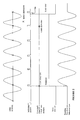
- the Zero Crossing point is defined as a point in time once per cycle of the AC component of the Ring Signal, where the AC voltage crosses zero volts (see Fig 2).
- ISR Interrupt Service Routine
- the ISR program controls the application and removal of ring to the subscriber's line by writing to appropriate registers on the signal processor module (18).
- the timing of the application and removal of ring signal is controlled by maintaining counters in reference to internal tables, which contain timing information appropriate for each of the possible ring cadences.
- the counters track the number of times that the ISR has been called, and if ring for any particular subscriber needs to switched on or off. In this way, writing to the HDSP module registers which initiate application or removal of ring only happens at the Zero Crossing Point of the Ring Signal.
- the signal processor modules contain edge-triggered timers, which are also synchronised to the pulses that occur on the Zero Cross Interrupt line (19). These timers are used to determine the point 2 ms before the next expected Zero Crossing Point. This is done by subtracting 2 ms from the time between the last two received Zero Crossing Point pulses.
- the signal processing module When the ISR on the Interface Module writes to the appropriate signal processing register to apply ring to a particular subscriber line, the signal processing module immediately initiates the actuation (apply ring) of the Ring Relay via lower level modules (20,10,21). When the ISR on the Interface Module writes to the appropriate signal processing register to remove ring to a particular subscriber line, the signal processor waits until the next point in time 2 ms before the next expected Zero Crossing Point before initiating the actuation (remove ring) of the Ring Relay via lower level modules (20,10,21).
- the code running on the Embedded Auxiliary Processor on the Interface Module will set up the appropriate internal registers to allow the ISR code to initiate the application of distinctive ring cadence to the subscriber line.
- the ISR will write to the appropriate signal processor register to apply ring, then wait for 4 cycles before writing to the appropriate signal processor register to remove ring, then wait for 6 cycles before writing to the appropriate signal processor register to apply ring again, thus repeating the cycle.
- the ring will be removed 2ms before the required point.
Landscapes
- Engineering & Computer Science (AREA)
- Signal Processing (AREA)
- Devices For Supply Of Signal Current (AREA)
- Electrical Discharge Machining, Electrochemical Machining, And Combined Machining (AREA)
- Aeration Devices For Treatment Of Activated Polluted Sludge (AREA)
- Stringed Musical Instruments (AREA)
- Exchange Systems With Centralized Control (AREA)
Abstract
- Generate an interrupt signal that is synchronised with one zero crossing of every ring cycle of said ring signals;
- Cause said auxiliary processor means to count a predetermined number of zero crosses and then turn said ring signal off,
Description
- Generate an interrupt signal that is synchronised with one zero crossing of every ring cycle of said ring signals;
- Cause said auxiliary processor means to count a predetermined number of zero crosses and then turn said ring signal off,
- Synchronising the actuation of the Ring Relay to the Zero Crossing Point of the Ring Signal for application of ring, and
- Synchronising the actuation of the Ring Relay to the point 2 ms before the Zero Crossing Point of the Ring Signal for removal of ring,
Claims (2)
- A method of providing an accurate distinctive ring signal of a selected predetermined cadence in a multi-service access platform arrangement that includes a central processor means, a plurality of line card means each of which includes an auxiliary processor means and controllable relay means, said relay means controllably connecting ring signals to a plurality of subscriber connected to the associated line card means, said method comprising the steps of:whereby an accurate distinctive ring cadence is obtained.Generate an interrupt signal that is synchronised with one zero crossing of every ring cycle of said ring signals;Cause said auxiliary processor means to count a predetermined number of zero crosses and then turn said ring signal off,
- A method of managing the generation of ring signal cadence in a multi-service access platform arrangement that includes a central processor means, a plurality of line card means each of which includes an auxiliary processor means and controllable relay means, said relay means controllably connecting ring signals to a plurality of subscriber connected to the associated line card means, said method comprising the step of controlling ring cadence of ring signal applied to a subscriber line associated with a line card, with an auxiliary processor means associated with said line card.
Applications Claiming Priority (2)
| Application Number | Priority Date | Filing Date | Title |
|---|---|---|---|
| AUPR2187A AUPR218700A0 (en) | 2000-12-22 | 2000-12-22 | Method of generating accurate ring cadence |
| AUPR218700 | 2000-12-22 |
Publications (3)
| Publication Number | Publication Date |
|---|---|
| EP1239683A2 true EP1239683A2 (en) | 2002-09-11 |
| EP1239683A3 EP1239683A3 (en) | 2005-11-23 |
| EP1239683B1 EP1239683B1 (en) | 2007-05-09 |
Family
ID=3826221
Family Applications (1)
| Application Number | Title | Priority Date | Filing Date |
|---|---|---|---|
| EP01403311A Expired - Lifetime EP1239683B1 (en) | 2000-12-22 | 2001-12-20 | Method of generating an accurate ring cadence |
Country Status (5)
| Country | Link |
|---|---|
| EP (1) | EP1239683B1 (en) |
| JP (1) | JP2002218056A (en) |
| AT (1) | ATE362276T1 (en) |
| AU (1) | AUPR218700A0 (en) |
| DE (1) | DE60128327T2 (en) |
Family Cites Families (3)
| Publication number | Priority date | Publication date | Assignee | Title |
|---|---|---|---|---|
| US4435803A (en) * | 1980-03-31 | 1984-03-06 | International Telephone And Telegraph Corporation | Analog subscriber/trunk module with shared ringing source and ring-trip |
| US4675898A (en) * | 1984-12-07 | 1987-06-23 | Buscom Systems, Inc. | Single tone telephone receiver |
| GB2303271B (en) * | 1995-07-10 | 1999-07-14 | Hong Kong Telecommunications L | Telephone network |
-
2000
- 2000-12-22 AU AUPR2187A patent/AUPR218700A0/en not_active Abandoned
-
2001
- 2001-12-20 EP EP01403311A patent/EP1239683B1/en not_active Expired - Lifetime
- 2001-12-20 DE DE60128327T patent/DE60128327T2/en not_active Expired - Lifetime
- 2001-12-20 AT AT01403311T patent/ATE362276T1/en not_active IP Right Cessation
- 2001-12-21 JP JP2001388854A patent/JP2002218056A/en not_active Withdrawn
Also Published As
| Publication number | Publication date |
|---|---|
| EP1239683A3 (en) | 2005-11-23 |
| DE60128327T2 (en) | 2008-01-10 |
| ATE362276T1 (en) | 2007-06-15 |
| DE60128327D1 (en) | 2007-06-21 |
| EP1239683B1 (en) | 2007-05-09 |
| JP2002218056A (en) | 2002-08-02 |
| AUPR218700A0 (en) | 2001-01-25 |
Similar Documents
| Publication | Publication Date | Title |
|---|---|---|
| EP0121410A1 (en) | Bus-configured local area network with data exchange capability | |
| US4757521A (en) | Synchronization method and apparatus for a telephone switching system | |
| US5220561A (en) | Data transfer between high bit rate buses via unshielded low bit rate bus | |
| US5406623A (en) | Method and apparatus for ringing telephone stations | |
| US4081613A (en) | Bi-directional signalling arrangement for telecommunications systems | |
| WO1993002513A1 (en) | Basic rate interface | |
| EP1239683B1 (en) | Method of generating an accurate ring cadence | |
| US5144624A (en) | Direct digital access telecommunication system with signaling bit detection | |
| US5228081A (en) | Ringing signal control circuit for an enhanced subscriber line interface | |
| EP0373887B1 (en) | Telephone ringing detector | |
| US4403320A (en) | Line status detection in a digital concentrator system | |
| US4075430A (en) | Line signalling over common highway for telecommunications system | |
| JPH09298762A (en) | Signal recognition device using prosodic table | |
| US3581020A (en) | Ringing tone distribution circuits | |
| EP0048129A1 (en) | Digital concentrator | |
| JPH07221746A (en) | Synchronous circuit | |
| EP0026020B1 (en) | Telephone set | |
| RU2124815C1 (en) | Method and device for detection of state of telephone lines in electronic exchange system | |
| US5230018A (en) | Communication system for activating an optical display in a communication terminal of a communication switching station | |
| JP2718673B2 (en) | Bidirectional transmission method and apparatus using two-wire system | |
| CA2019002C (en) | Data transfer between high bit rate buses via unshielded low bit rate bus | |
| JP3516152B2 (en) | Synchronization establishing device | |
| SU1765827A1 (en) | Priority interrupter | |
| JP2924950B2 (en) | Interface circuit for electronic exchange | |
| EP0233457A1 (en) | Improvements to an operation control system of one or more apparatuses |
Legal Events
| Date | Code | Title | Description |
|---|---|---|---|
| PUAI | Public reference made under article 153(3) epc to a published international application that has entered the european phase |
Free format text: ORIGINAL CODE: 0009012 |
|
| AK | Designated contracting states |
Kind code of ref document: A2 Designated state(s): AT BE CH CY DE DK ES FI FR GB GR IE IT LI LU MC NL PT SE TR |
|
| AX | Request for extension of the european patent |
Free format text: AL;LT;LV;MK;RO;SI |
|
| PUAL | Search report despatched |
Free format text: ORIGINAL CODE: 0009013 |
|
| AK | Designated contracting states |
Kind code of ref document: A3 Designated state(s): AT BE CH CY DE DK ES FI FR GB GR IE IT LI LU MC NL PT SE TR |
|
| AX | Request for extension of the european patent |
Extension state: AL LT LV MK RO SI |
|
| RIC1 | Information provided on ipc code assigned before grant |
Ipc: 7H 04M 3/06 B Ipc: 7H 04Q 1/30 A |
|
| 17P | Request for examination filed |
Effective date: 20051222 |
|
| AKX | Designation fees paid |
Designated state(s): AT BE CH CY DE DK ES FI FR GB GR IE IT LI LU MC NL PT SE TR |
|
| GRAP | Despatch of communication of intention to grant a patent |
Free format text: ORIGINAL CODE: EPIDOSNIGR1 |
|
| GRAS | Grant fee paid |
Free format text: ORIGINAL CODE: EPIDOSNIGR3 |
|
| RAP1 | Party data changed (applicant data changed or rights of an application transferred) |
Owner name: ALCATEL LUCENT |
|
| GRAA | (expected) grant |
Free format text: ORIGINAL CODE: 0009210 |
|
| AK | Designated contracting states |
Kind code of ref document: B1 Designated state(s): AT BE CH CY DE DK ES FI FR GB GR IE IT LI LU MC NL PT SE TR |
|
| PG25 | Lapsed in a contracting state [announced via postgrant information from national office to epo] |
Ref country code: CH Free format text: LAPSE BECAUSE OF FAILURE TO SUBMIT A TRANSLATION OF THE DESCRIPTION OR TO PAY THE FEE WITHIN THE PRESCRIBED TIME-LIMIT Effective date: 20070509 Ref country code: FI Free format text: LAPSE BECAUSE OF FAILURE TO SUBMIT A TRANSLATION OF THE DESCRIPTION OR TO PAY THE FEE WITHIN THE PRESCRIBED TIME-LIMIT Effective date: 20070509 Ref country code: LI Free format text: LAPSE BECAUSE OF FAILURE TO SUBMIT A TRANSLATION OF THE DESCRIPTION OR TO PAY THE FEE WITHIN THE PRESCRIBED TIME-LIMIT Effective date: 20070509 |
|
| REG | Reference to a national code |
Ref country code: GB Ref legal event code: FG4D |
|
| REG | Reference to a national code |
Ref country code: CH Ref legal event code: EP |
|
| REG | Reference to a national code |
Ref country code: IE Ref legal event code: FG4D |
|
| REF | Corresponds to: |
Ref document number: 60128327 Country of ref document: DE Date of ref document: 20070621 Kind code of ref document: P |
|
| PG25 | Lapsed in a contracting state [announced via postgrant information from national office to epo] |
Ref country code: SE Free format text: LAPSE BECAUSE OF FAILURE TO SUBMIT A TRANSLATION OF THE DESCRIPTION OR TO PAY THE FEE WITHIN THE PRESCRIBED TIME-LIMIT Effective date: 20070809 |
|
| PG25 | Lapsed in a contracting state [announced via postgrant information from national office to epo] |
Ref country code: ES Free format text: LAPSE BECAUSE OF FAILURE TO SUBMIT A TRANSLATION OF THE DESCRIPTION OR TO PAY THE FEE WITHIN THE PRESCRIBED TIME-LIMIT Effective date: 20070820 |
|
| ET | Fr: translation filed | ||
| NLV1 | Nl: lapsed or annulled due to failure to fulfill the requirements of art. 29p and 29m of the patents act | ||
| REG | Reference to a national code |
Ref country code: CH Ref legal event code: PL |
|
| PG25 | Lapsed in a contracting state [announced via postgrant information from national office to epo] |
Ref country code: AT Free format text: LAPSE BECAUSE OF FAILURE TO SUBMIT A TRANSLATION OF THE DESCRIPTION OR TO PAY THE FEE WITHIN THE PRESCRIBED TIME-LIMIT Effective date: 20070509 |
|
| PG25 | Lapsed in a contracting state [announced via postgrant information from national office to epo] |
Ref country code: BE Free format text: LAPSE BECAUSE OF FAILURE TO SUBMIT A TRANSLATION OF THE DESCRIPTION OR TO PAY THE FEE WITHIN THE PRESCRIBED TIME-LIMIT Effective date: 20070509 |
|
| PG25 | Lapsed in a contracting state [announced via postgrant information from national office to epo] |
Ref country code: DK Free format text: LAPSE BECAUSE OF FAILURE TO SUBMIT A TRANSLATION OF THE DESCRIPTION OR TO PAY THE FEE WITHIN THE PRESCRIBED TIME-LIMIT Effective date: 20070509 Ref country code: PT Free format text: LAPSE BECAUSE OF FAILURE TO SUBMIT A TRANSLATION OF THE DESCRIPTION OR TO PAY THE FEE WITHIN THE PRESCRIBED TIME-LIMIT Effective date: 20071009 Ref country code: NL Free format text: LAPSE BECAUSE OF FAILURE TO SUBMIT A TRANSLATION OF THE DESCRIPTION OR TO PAY THE FEE WITHIN THE PRESCRIBED TIME-LIMIT Effective date: 20070509 |
|
| PLBE | No opposition filed within time limit |
Free format text: ORIGINAL CODE: 0009261 |
|
| STAA | Information on the status of an ep patent application or granted ep patent |
Free format text: STATUS: NO OPPOSITION FILED WITHIN TIME LIMIT |
|
| 26N | No opposition filed |
Effective date: 20080212 |
|
| PG25 | Lapsed in a contracting state [announced via postgrant information from national office to epo] |
Ref country code: IT Free format text: LAPSE BECAUSE OF FAILURE TO SUBMIT A TRANSLATION OF THE DESCRIPTION OR TO PAY THE FEE WITHIN THE PRESCRIBED TIME-LIMIT Effective date: 20070509 Ref country code: GR Free format text: LAPSE BECAUSE OF FAILURE TO SUBMIT A TRANSLATION OF THE DESCRIPTION OR TO PAY THE FEE WITHIN THE PRESCRIBED TIME-LIMIT Effective date: 20070810 |
|
| PG25 | Lapsed in a contracting state [announced via postgrant information from national office to epo] |
Ref country code: MC Free format text: LAPSE BECAUSE OF NON-PAYMENT OF DUE FEES Effective date: 20071231 |
|
| PG25 | Lapsed in a contracting state [announced via postgrant information from national office to epo] |
Ref country code: IE Free format text: LAPSE BECAUSE OF NON-PAYMENT OF DUE FEES Effective date: 20071220 |
|
| PG25 | Lapsed in a contracting state [announced via postgrant information from national office to epo] |
Ref country code: CY Free format text: LAPSE BECAUSE OF FAILURE TO SUBMIT A TRANSLATION OF THE DESCRIPTION OR TO PAY THE FEE WITHIN THE PRESCRIBED TIME-LIMIT Effective date: 20070509 |
|
| PG25 | Lapsed in a contracting state [announced via postgrant information from national office to epo] |
Ref country code: LU Free format text: LAPSE BECAUSE OF NON-PAYMENT OF DUE FEES Effective date: 20071220 |
|
| PG25 | Lapsed in a contracting state [announced via postgrant information from national office to epo] |
Ref country code: TR Free format text: LAPSE BECAUSE OF FAILURE TO SUBMIT A TRANSLATION OF THE DESCRIPTION OR TO PAY THE FEE WITHIN THE PRESCRIBED TIME-LIMIT Effective date: 20070509 |
|
| REG | Reference to a national code |
Ref country code: FR Ref legal event code: GC Effective date: 20131018 |
|
| REG | Reference to a national code |
Ref country code: FR Ref legal event code: RG Effective date: 20141016 |
|
| REG | Reference to a national code |
Ref country code: FR Ref legal event code: CA Effective date: 20150521 |
|
| REG | Reference to a national code |
Ref country code: FR Ref legal event code: CA Effective date: 20150521 |
|
| REG | Reference to a national code |
Ref country code: FR Ref legal event code: PLFP Year of fee payment: 15 |
|
| PGFP | Annual fee paid to national office [announced via postgrant information from national office to epo] |
Ref country code: DE Payment date: 20151211 Year of fee payment: 15 Ref country code: GB Payment date: 20151221 Year of fee payment: 15 |
|
| PGFP | Annual fee paid to national office [announced via postgrant information from national office to epo] |
Ref country code: FR Payment date: 20151221 Year of fee payment: 15 |
|
| REG | Reference to a national code |
Ref country code: DE Ref legal event code: R119 Ref document number: 60128327 Country of ref document: DE |
|
| GBPC | Gb: european patent ceased through non-payment of renewal fee |
Effective date: 20161220 |
|
| REG | Reference to a national code |
Ref country code: FR Ref legal event code: ST Effective date: 20170831 |
|
| PG25 | Lapsed in a contracting state [announced via postgrant information from national office to epo] |
Ref country code: FR Free format text: LAPSE BECAUSE OF NON-PAYMENT OF DUE FEES Effective date: 20170102 |
|
| PG25 | Lapsed in a contracting state [announced via postgrant information from national office to epo] |
Ref country code: DE Free format text: LAPSE BECAUSE OF NON-PAYMENT OF DUE FEES Effective date: 20170701 Ref country code: GB Free format text: LAPSE BECAUSE OF NON-PAYMENT OF DUE FEES Effective date: 20161220 |