EP1239562A2 - Gas filled switching electric discharge tube - Google Patents
Gas filled switching electric discharge tube Download PDFInfo
- Publication number
- EP1239562A2 EP1239562A2 EP02251412A EP02251412A EP1239562A2 EP 1239562 A2 EP1239562 A2 EP 1239562A2 EP 02251412 A EP02251412 A EP 02251412A EP 02251412 A EP02251412 A EP 02251412A EP 1239562 A2 EP1239562 A2 EP 1239562A2
- Authority
- EP
- European Patent Office
- Prior art keywords
- electrode
- electric discharge
- cylindrical body
- discharge tube
- gas filled
- Prior art date
- Legal status (The legal status is an assumption and is not a legal conclusion. Google has not performed a legal analysis and makes no representation as to the accuracy of the status listed.)
- Granted
Links
Images




Classifications
-
- H—ELECTRICITY
- H01—ELECTRIC ELEMENTS
- H01T—SPARK GAPS; OVERVOLTAGE ARRESTERS USING SPARK GAPS; SPARKING PLUGS; CORONA DEVICES; GENERATING IONS TO BE INTRODUCED INTO NON-ENCLOSED GASES
- H01T2/00—Spark gaps comprising auxiliary triggering means
-
- H—ELECTRICITY
- H01—ELECTRIC ELEMENTS
- H01T—SPARK GAPS; OVERVOLTAGE ARRESTERS USING SPARK GAPS; SPARKING PLUGS; CORONA DEVICES; GENERATING IONS TO BE INTRODUCED INTO NON-ENCLOSED GASES
- H01T1/00—Details of spark gaps
- H01T1/20—Means for starting arc or facilitating ignition of spark gap
- H01T1/22—Means for starting arc or facilitating ignition of spark gap by the shape or the composition of the electrodes
Definitions
- the present invention relates to a gas filled switching electric discharge tube. More particularly, the present invention relates to the structure of a gas filled switching electric discharge tube in which the voltage characteristic at the time of electric discharge is improved.
- the gas filled switching electric discharge tube includes: a cylindrical body made of insulating material such as ceramic; and a first electrode and a second electrode for airtightly closing both ends of the cylindrical body, wherein an electric discharge gap is formed between the first electrode face of the first electrode and the second electrode face of the second electrode, and gas is filed into an airtightly closed space which is formed in the cylindrical body including the electric discharge gap. Due to the above structure, electric discharge is generated between the first electrode face and the second electrode face.
- the electric discharge voltage (FVs) of the first time is necessarily higher than the electric discharge voltage (Vs) of the second time and the times after that.
- the reason why is that, as the switching electric discharge tube has been left in a dark place, it is impossible for photo-electrons, which always excite the filled gas in a bright state, to provide an excitation effect (the photoelectron effect).
- Metallized faces are formed on both end faces, which come into contact with the electrodes, of the cylindrical body made of ceramic, and trigger wires are provided which come into contact with the metallized faces and extend on an inner wall face of the cylindrical body, or alternatively trigger wires are provided which do not come into contact with the metallized faces but extend on the inner wall face of the cylindrical body.
- the electrode is made of a low thermal expansion alloy, the coefficient of thermal expansion of which is close to that of a ceramic, such as covar or iron-nickel alloy.
- a ceramic such as covar or iron-nickel alloy.
- the electrode itself is made of copper, and hydrogen gas is partially filled into the electric discharge tube.
- the electrode made of covar or iron-nickel alloy is plated with copper or a copper alloy.
- an object of the present invention is to provide a gas filled switching electric discharge tube, the characteristic of which will be described as follows.
- the low electric conductivity which is a property of the material composing the electrode itself, is improved by conducting plating on the electrode. Further, when an interval of the electric discharge gap and an interval between the electrode face and the trigger wires are regulated, the extension of the life of electric discharge and the prevention of a rise in the FVs characteristic in the case of a life test can be accomplished.
- a gas filled switching electric discharge tube comprising: a cylindrical body made of insulating material; a first and a second electrode for airtightly closing both ends of the cylindrical body so that an electric discharge gap is formed between a first electrode face of the first electrode and a second electrode face of the second electrode, and an airtightly closed space formed in the cylindrical body being filled with gas; metallized faces formed on both faces of the cylindrical body, the first and the second electrode being joined to the cylindrical body on both the end faces of the cylindrical body; first trigger wires formed on an inner wall face of the cylindrical body, connected with the metallized faces; second trigger wires formed on the inner wall face of the cylindrical body, not connected with the metallized faces; at least one of the first electrode face of the first electrode and the second electrode face of the second electrode is plated with copper or silver; and an interval of the electric discharge gap being made to be larger than a distance from the second trigger wires to the first or the second electrode face.
- the cylindrical body is a cylinder
- the first and the second electrode face are substantially circular and formed around the central axis of the cylindrical body
- the first and the second electrode face are arranged being symmetrically opposed to each other
- the first trigger wires extend from the metallized faces in the axial direction on the inner wall face of the cylindrical body, however, the first trigger wires do not reach a central portion of the cylindrical body
- the second trigger wires extend in the central portion of the cylindrical body in the axial direction
- a distance (d) from the second trigger wires to the first or second electrode face is a radial distance from an outer surface of these electrodes to an inner wall of the cylindrical body.
- the electric discharge gap (t) is a distance between tips of the first electrode face and the second electrode face facing to each other.
- At least one of the first electrode face of the first electrode and the second electrode face of the second electrode is plated with copper or silver so that a thickness of the plated layer is 10-20 ⁇ m.
- the number of the second trigger wires is larger than the number of the second trigger wires.
- the first trigger wires extend from the metallized face in the axial direction along an inner wall face of the cylindrical body, however, they do not extend over a central area, and, on the other hand, the second trigger wires extend in the axial direction at the central area.
- the first trigger wires include a pair thereof spaced by 180°, one extending in the axial direction from one of the metallized faces and the other extending in the axial direction from the other of the metallized faces.
- the pair of the first trigger wires are respectively composed of a plurality of trigger lines arranged close and parallel to each other.
- the length of the first trigger wire in the axial direction is not more than 1/3 of the length of the cylindrical body in the axial direction.
- a plurality of the second trigger wires are arranged at substantially regular intervals between a pair of the first trigger wires which are arranged at an interval of 180°.
- the length of the second trigger wire in the axial direction is not less than 1/2 of the length of the cylindrical body in the axial direction.
- a plurality of recessed portions are provided on at least one of the first and the second electrode faces.
- the recess portions are hemispherical recess portions.
- the plurality of recess portions are uniformly arranged at regular pitches of 0.1-1.0 mm.
- the first and the second electrode faces are arranged to be symmetrically opposed to each other, central portions of the electrode faces are hollowed with respect to the peripheral portion, and the plurality of recess portions are formed in the hollow portion.
- the cylindrical body is made of ceramic, and the first and the second electrode are made of iron-nickel alloy such as 42 alloy or iron-nickel-cobalt alloy such as covar.
- the first and the second electrode are joined to the cylindrical body by means of soldering.
- Fig. 1 is a sectional view of a gas filled switching electric discharge tube of an embodiment of the present invention
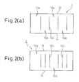
- Figs. 2(a) and 2(b) are developed views of a cylindrical body made of ceramic used for the electric discharge tube of the present invention.
- the gas filled switching electric discharge tube of the present invention includes: a cylindrical body 1 made of insulating material such as ceramic; and a first electrode 2 and a second electrode 3 for airtightly closing both end portions of the cylindrical body 1.
- the cylindrical body 1 is joined to the first electrode 2 and the second electrode 3 by the solder 4.
- Both end faces of the cylindrical body 1 made of ceramic are formed into the metallized faces 12, 14.
- the carbon trigger wires 10a, 10b on the sides of the metallized faces 12, 14 are arranged at an interval of 90° and alternately extended from the metallized faces 12, 14 on the inner wall face of the cylindrical body 10 made of ceramic in the axial direction, that is, four carbon trigger wires are alternately extended on the inner wall face of the cylindrical body 10 in the axial direction.
- Lengths in the axial direction of the carbon trigger wires 10a, 10b on the sides of the metallized faces 12, 14 are relatively small and approximately not more than 1/4 of the length of the cylindrical body 1, made of ceramic, in the axial direction.
- the carbon trigger wires 10c extend in the axial direction in the central portion on the inner wall face of the cylindrical body 1 made of ceramic.
- one carbon trigger wire 10c is arranged at the intermediate position between the carbon trigger wires 10a, 10b on the sides of the metallized faces 12, 14, that is, four carbon trigger wires are arranged in total.
- the trigger wires 10a, 10b, 10c are arranged at regular intervals of about 45° in the circumferential direction. These trigger wires 10c arranged at the center do not come into contact with the metallized faces 12, 14.
- These trigger wires 10c arranged at the center are relatively longer than the carbon trigger wires 10a, 10b arranged on the sides of the metallized faces 12, 14. Lengths of these trigger wires 10c are approximately not less than 1/2 of the length of the cylindrical body 1 made of ceramic in the axial direction.
- one carbon trigger wire 10a and one carbon trigger wire 10b are arranged at an interval of 180°.
- three carbon trigger wires 10c are arranged every between the carbon trigger wires 10a, 10b on side of the metallized faces 12, 14 at regular intervals (about 45°), that is, six carbon trigger wires 10c are arranged in total.
- the electrodes 2, 3 are joined to the cylindrical body 10 made of ceramic by the solder 4, the electrodes 2, 3 are made of low thermal expansion material of iron-nickel alloy such as 42 alloy or a iron-nickel-cobalt alloy such as covar. Profiles of these electrodes 2, 3 are the same, and the electrode faces 20, 30 are formed to be substantially circular around the central axis of the cylindrical body 1 made of ceramic. These electrode faces 20, 30 are arranged being symmetrically opposed to each other. Between these electrode faces 20, 30, the electric discharge gap 40 is formed. As widely known, the inside of the cylindrical body 1 including the electric discharge gap 40 is filled with inert gas such as argon gas. When a predetermined voltage is impressed between the electrodes 2, 3, electric discharge occurs between the electrode faces 20, 30.
- inert gas such as argon gas.
- Fig. 3(a) is a sectional view showing an electrode used for a gas filled switching electric discharge tube of an embodiment of the present invention shown in Fig. 1, and Fig. 3(b) is a plan view of the electrode, wherein the view is taken from the electrode face side.
- a pair of electrodes 2, 3 are the same in the size and profile. Each electrode 2, 3 is integrally formed into one body, and the pair of electrodes 2, 3 are arranged symmetrically with each other.
- the peripheral portions of the electrodes 2, 3 are formed into the flat flange portions 2a, 3a which are joined to the end faces of the cylindrical body 1 by the solder 4.
- the inside central portions of the electrodes 2, 3, which are opposed to each other, are formed into the electrode faces 20, 30.
- the substantially circular electrode faces 20, 30 have a relatively large area.
- the central portion 21 of each electrode face 20, 30, which occupies most of the area of the electrode, is uniformly hollowed by the depth e with respect to the peripheral portion 22 of the electrode.
- a plurality of hemispherical recess portions 23 are formed.
- the plurality of hemispherical recess portions 23 are uniformly arranged at regular pitches of 0.8 mm.
- the electrode faces 20, 30 having the plurality of hemispherical recess portions 23 are coated with an electric discharge activating coating agent.
- an electric discharge activating coating agent to be coated When a quantity of the electric discharge activating coating agent to be coated is appropriately adjusted, it is possible to extend the life of electric discharge.
- the interval t of the electric discharge gap 40 which is measured at the end portions of the electrode faces 20, 30, is larger than the distance d which is a distance from the carbon trigger wire 10c at the central portion to the electrode face 20, 30, that is, a distance in the radial direction from the outer circumference of the electrode face 20, 30 to the inner wall of the cylindrical body made of ceramic.
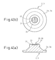
- Fig. 4(a) is a sectional view of a gas filled switching electrode used for an electric discharge tube of a comparative example
- Fig. 4(b) is a plan view of the electrode which is taken from the electrode face side.
- Areas of the electrode faces 20, 30 of this comparative example are smaller than those of the embodiment of the present invention, and a pitch of the plurality of hemispherical recess portions 23 provided on the electrode face is smaller than that of the electrode of the aforementioned embodiment (The pitch is 0.4 mm.).
- Other points of the comparative example are the same as those of the electrode of the embodiment of the present invention.
- the electrode shown in this comparative example is adopted and the gas filled switching electric discharge tube shown in Fig. 1 is composed, that is, when the electrodes 2, 3 shown in Fig. 1 are replaced with the electrodes shown in Fig. 4(a) and 4(b), the distance d in the radial direction from the outer circumference of the electrode face 20, 30 to the inner wall of the cylindrical body made of ceramic is relatively large. Therefore, it is difficult for the interval t of the electric discharge gap, which is measured at the end portions of the electrode faces 20, 30, to be made larger than the distance d.
- the characteristics of the gas filled switching electric discharge tube of the present invention are expressed by the following items (1) and (2).
- the FVs characteristic is excellent when only the copper plated layer is provided.
- the most appropriate FVs was exhibited when the plate layer thickness was 10 ⁇ m to 20 ⁇ m. The reason is that the following measurement results were obtained.
- test conditions in the following tests (a) to (c) are described as follows.
- Test Conditions Ignitor manufactured by Stanley Denki K. K. Test cycle: operation for one second/stoppage for one second (about 100 Hz) Test state: four sheathed insulating tubes Interval of measurement: initial stage ⁇ 50,000 times ⁇ 100,000 times ⁇ 150,000 times ⁇ 200,000 times
- the electric discharge tube is left for not less than 24 hours and then measured for each measurement interval.
- the electric discharge tube is left for 24 hours and further left for not less than 48 hours and then measured again.
- Measuring apparatus Tektronix TDS 544A oscilloscope/Tektronix P6015 voltage probe
- the FVs characteristic can be kept low and the obtained result is excellent.
- the electric discharge gap is set larger than the interval between the electric discharge face and the trigger wires provided on the inner wall of the cylindrical body, it becomes possible to facilitate the stabilization of the FVs characteristic in the case of electrically discharging in a dark place.
- the primary electric discharge is conducted in the electric discharge gap, however, the following operation is conducted until the electric discharge is started. (1) When an electric potential difference is generated between both end portions of the electrodes, an initial voltage is generated from the trigger wires and the filled gas is excited.
Landscapes
- Gas-Filled Discharge Tubes (AREA)
- Vessels And Coating Films For Discharge Lamps (AREA)
- Testing Relating To Insulation (AREA)
Abstract
Description
Concerning the material of the electrode, as the electrode is soldered to a ceramic, covar or iron-nickel alloy, the linear thermal expansion coefficient of which is similar to that of a ceramic, is adopted as described before. However, the electric conductivity of these materials is approximately only 15% of the electric conductivity of copper. Therefore, generation of the creeping corona discharge in a dark place is delayed, which raises the switching electric discharge starting voltage FVs of the first electric discharge to be higher than that of the second electric discharge. Therefore, in the present invention, when the entire face of the electrode was plated with copper, the switching electric discharge starting voltage of FVs could be made close to the electric discharge starting voltage of Vs of the second discharge and after, and a further fluctuation of the electric discharge characteristic of the electrode among the manufacturing lots could be reduced. That is, the fluctuation of about 15% was reduced to the fluctuation of about 5%.


Ignitor: manufactured by Stanley Denki K. K.
Test cycle: operation for one second/stoppage for one second (about 100 Hz)
Test state: four sheathed insulating tubes
Interval of measurement: initial stage·50,000 times·100,000 times·150,000 times·200,000 times
| <Sample No. 1> Copper Plated Layer Thickness Is Smaller Than 10 | |||||||
| Start | |||||||
| 50000 | 100000 | 150000 | 200000 | Left over 48 Hours | |||
| FVs | 840 | 944 | 976 | 968 | 986 | 982 | |
| Vs | 828 | 812 | 812 | 776 | 796 | 796 | |
| Unit: V |
| <Sample No. 2> Copper Plated Layer Thickness Is Smaller Than 20 | |||||||
| Start | |||||||
| 50000 | 100000 | 150000 | 200000 | Left over 48 Hours | |||
| FVs | 837 | 804 | 800 | 764 | 738 | 830 | |
| Vs | 772 | 704 | 696 | 680 | 678 | 688 | |
| Unit: V |
| <Sample No. 3> Copper Plated Layer Thickness Is 10 µm - 20 | |||||||
| Start | |||||||
| 50000 | 100000 | 150000 | 200000 | Left over 48 Hours | |||
| FVs | 844 | 832 | 812 | 882 | 876 | 840 | |
| Vs | 820 | 772 | 756 | 752 | 744 | 748 | |
| Unit: V |
Claims (17)
- A gas filled switching electric discharge tube comprising:a cylindrical body made of insulating material;a first electrode and a second electrode for airtightly closing both ends of the cylindrical body so that an electric discharge gap is formed between a first electrode face of the first electrode and a second electrode face of the second electrode, and an airtightly closed space formed in the cylindrical body being filled with gas;metallized faces formed on both faces of the cylindrical body, the first electrode and the second electrode being joined to the cylindrical body on both the end faces of the cylindrical body;first trigger wires formed on an inner wall face of the cylindrical body, connected with the metallized faces;second trigger wires formed on the inner wall face of the cylindrical body, not connected with the metallized faces;at least one of the first electrode face of the first electrode and the second electrode face of the second electrode is plated with copper or silver; andan interval of the electric discharge gap being made to be larger than a distance from the second trigger wires to the first electrode face or the second electrode face.
- A gas filled switching electric discharge tube according to claim 1, wherein the cylindrical body is a cylinder, the first and the second electrode face are substantially circular and formed around the central axis of the cylindrical body, the first electrode face and the second electrode face are arranged being symmetrically opposed to each other, the first trigger wires extend from the metallized faces in the axial direction on the inner wall face of the cylindrical body but the first trigger wires do not reach a central portion of the cylindrical body, the second trigger wires extend in the central portion of the cylindrical body in the axial direction, and a distance (d) from the second trigger wires to the first electrode face or the second electrode face is a radial distance from an outer surface of these electrodes to an inner wall of the cylindrical body.
- A gas filled switching electric discharge tube according to claim 2, wherein the electric discharge gap (t) is a distance between tips of the first electrode face and the second electrode face facing each other.
- A gas filled switching electric discharge tube according to claim 2, wherein at least one of the first electrode face of the first electrode and the second electrode face of the second electrode is plated with copper or silver so that a thickness of the plated layer is 10-20 µm.
- A gas filled switching electric discharge tube according to claim 1, wherein the number of the second trigger wires is larger than the number of the first trigger wires.
- A gas filled switching electric discharge tube according to claim 5, wherein the first trigger wires extend from the metallized face in the axial direction along an inner wall face of the cylindrical body, however, do not extend over a central area, and, on the other hand, the second trigger wires extend in the axial direction at the central area.
- A gas filled switching electric discharge tube according to claim 6, wherein the first trigger wires include a pair thereof spaced by 180°, one extending in the axial direction from one of the metallized faces and the other extending in the axial direction from the other of the metallized faces.
- A gas filled switching electric discharge tube according to claim 7, wherein the pair of the first trigger wires are respectively composed of a plurality of trigger wires arranged close and parallel to each other.
- A gas filled switching electric discharge tube according to claim 6, wherein the length of the first trigger wire in the axial direction is not more than 1/3 of the length of the cylindrical body in the axial direction.
- A gas filled switching electric discharge tube according to claim 6, wherein a plurality of the second trigger wires are arranged at substantially regular intervals between a pair of the first trigger wires which are arranged at an interval of 180°.
- A gas filled switching electric discharge tube according to claim 6, wherein the length of the second trigger wire in the axial direction is not less than 1/2 of the length of the cylindrical body in the axial direction.
- A gas filled switching electric discharge tube according to claim 1, wherein a plurality of recess portions are provided on at least one of the first and the second electrode faces.
- A gas filled switching electric discharge tube according to claim 12, wherein the recess portions are respectively hemispherical recess portions.
- A gas filled switching electric discharge tube according to claim 13, wherein the plurality of recess portions are uniformly arranged at regular pitches of 0.1 mm-1.0 mm.
- A gas filled switching electric discharge tube according to claim 1, wherein the first and the second electrode face are arranged symmetrically opposed to each other, central portions of the electrode faces are hollowed with respect to the peripheral portion, and the plurality of recess portions are formed in the hollow portion.
- A gas filled switching electric discharge tube according to claim 1, wherein the cylindrical body is made of ceramic, and the first electrode and the second electrode are made of iron-nickel alloy such as 42 alloy or an iron-nickel-cobalt alloy such as covar.
- A gas filled switching electric discharge tube according to claim 1, wherein the first electrode and the second electrode are joined to the cylindrical body by means of soldering.
Applications Claiming Priority (2)
| Application Number | Priority Date | Filing Date | Title |
|---|---|---|---|
| JP2001067414 | 2001-03-09 | ||
| JP2001067414A JP2002270329A (en) | 2001-03-09 | 2001-03-09 | Gas filled switching discharge tube |
Publications (3)
| Publication Number | Publication Date |
|---|---|
| EP1239562A2 true EP1239562A2 (en) | 2002-09-11 |
| EP1239562A3 EP1239562A3 (en) | 2003-09-17 |
| EP1239562B1 EP1239562B1 (en) | 2008-01-23 |
Family
ID=18925768
Family Applications (1)
| Application Number | Title | Priority Date | Filing Date |
|---|---|---|---|
| EP02251412A Expired - Lifetime EP1239562B1 (en) | 2001-03-09 | 2002-02-28 | Gas filled switching electric discharge tube |
Country Status (5)
| Country | Link |
|---|---|
| US (1) | US6617770B2 (en) |
| EP (1) | EP1239562B1 (en) |
| JP (1) | JP2002270329A (en) |
| KR (1) | KR100858904B1 (en) |
| DE (1) | DE60224740T2 (en) |
Cited By (1)
| Publication number | Priority date | Publication date | Assignee | Title |
|---|---|---|---|---|
| EP1538654A3 (en) * | 2003-10-06 | 2008-08-27 | Shinko Electric Industries Co., Ltd. | Discharge tube |
Families Citing this family (9)
| Publication number | Priority date | Publication date | Assignee | Title |
|---|---|---|---|---|
| JP4421191B2 (en) * | 2003-01-30 | 2010-02-24 | 新光電気工業株式会社 | Discharge tube |
| EP1612899A4 (en) * | 2003-04-10 | 2010-02-24 | Okaya Electric Industry Co | Discharge tube and surge absorbing device |
| US7122949B2 (en) * | 2004-06-21 | 2006-10-17 | Neocera, Inc. | Cylindrical electron beam generating/triggering device and method for generation of electrons |
| JP2006012519A (en) * | 2004-06-24 | 2006-01-12 | Shinko Electric Ind Co Ltd | Surface mount discharge tube |
| DE112006002464T5 (en) | 2005-09-14 | 2008-07-24 | Littelfuse, Inc., Des Plaines | Gas-filled surge arrester, activating connection, ignition strips and manufacturing process therefor |
| JP2008251389A (en) * | 2007-03-30 | 2008-10-16 | Okaya Electric Ind Co Ltd | Discharge tube |
| ES2387340T3 (en) * | 2007-12-21 | 2012-09-20 | Bae Systems Plc | High voltage switch |
| SI23691A (en) | 2011-03-21 | 2012-09-28 | ISKRA ZAĹ ÄŚITE d.o.o. | Gas discharge tube with metal body for high current surges |
| CN107706074B (en) * | 2017-09-25 | 2024-02-09 | 深圳市槟城电子股份有限公司 | Gas discharge tube |
Family Cites Families (10)
| Publication number | Priority date | Publication date | Assignee | Title |
|---|---|---|---|---|
| JPS61281489A (en) * | 1985-06-06 | 1986-12-11 | 株式会社サンコ−シャ | Lightning arrestor |
| EP0249796B1 (en) | 1986-06-18 | 1991-02-27 | Siemens Aktiengesellschaft | Gas discharge overtension arrester |
| JPH0362486A (en) * | 1989-07-28 | 1991-03-18 | Shinko Electric Ind Co Ltd | Gas-filled discharge tube for high voltage switch element |
| JPH0377292A (en) | 1989-08-18 | 1991-04-02 | Hitachi Cable Ltd | Electrode material for shock absorber and surge absorber using the same material |
| JPH0377293A (en) * | 1989-08-18 | 1991-04-02 | Hitachi Cable Ltd | Electrode material for shock absorber and surge absorber using the same material |
| JPH06324576A (en) * | 1993-05-11 | 1994-11-25 | Fuji Xerox Co Ltd | Transfer device of image forming device |
| JPH10335042A (en) * | 1997-03-31 | 1998-12-18 | Shinko Electric Ind Co Ltd | Discharge tube |
| JP3995339B2 (en) * | 1998-06-10 | 2007-10-24 | 新光電気工業株式会社 | Discharge tube |
| JP3627909B2 (en) * | 1999-07-12 | 2005-03-09 | 新光電気工業株式会社 | Discharge tube |
| JP2001093644A (en) * | 1999-07-16 | 2001-04-06 | Shinko Electric Ind Co Ltd | Discharge tube |
-
2001
- 2001-03-09 JP JP2001067414A patent/JP2002270329A/en active Pending
-
2002
- 2002-02-26 US US10/083,202 patent/US6617770B2/en not_active Expired - Lifetime
- 2002-02-28 DE DE60224740T patent/DE60224740T2/en not_active Expired - Lifetime
- 2002-02-28 EP EP02251412A patent/EP1239562B1/en not_active Expired - Lifetime
- 2002-03-08 KR KR1020020012539A patent/KR100858904B1/en not_active Expired - Fee Related
Cited By (1)
| Publication number | Priority date | Publication date | Assignee | Title |
|---|---|---|---|---|
| EP1538654A3 (en) * | 2003-10-06 | 2008-08-27 | Shinko Electric Industries Co., Ltd. | Discharge tube |
Also Published As
| Publication number | Publication date |
|---|---|
| KR100858904B1 (en) | 2008-09-17 |
| KR20020072238A (en) | 2002-09-14 |
| JP2002270329A (en) | 2002-09-20 |
| DE60224740T2 (en) | 2009-01-22 |
| US20030034730A1 (en) | 2003-02-20 |
| EP1239562B1 (en) | 2008-01-23 |
| US6617770B2 (en) | 2003-09-09 |
| EP1239562A3 (en) | 2003-09-17 |
| DE60224740D1 (en) | 2008-03-13 |
Similar Documents
| Publication | Publication Date | Title |
|---|---|---|
| US6617770B2 (en) | Gas filled switching electric discharge tube | |
| KR100498179B1 (en) | Spark plug | |
| CN100499017C (en) | Cold cathode discharge lamp | |
| US20080049370A1 (en) | Surge Absorber | |
| US20070216277A1 (en) | Spark plug for internal combustion engine | |
| US20050057135A1 (en) | Spark plug | |
| US8987981B2 (en) | Spark plug | |
| US6617804B2 (en) | Gas filled switching electric discharge tube | |
| KR20060058087A (en) | Surge absorber | |
| CN101490917A (en) | Spark plugs, especially for high pressure in the combustion chamber | |
| EP0869529B1 (en) | Discharge tube | |
| EP3499658B1 (en) | Spark plug | |
| EP3001520B1 (en) | Spark plug | |
| JPH0992429A (en) | Surge absorbing element | |
| JP5392490B2 (en) | Spark plug | |
| US7102289B2 (en) | Discharge tube | |
| JPH0633388U (en) | Discharge tube | |
| JP2003022885A (en) | Multi-pole spark plug and semi-surface multi-pole spark plug | |
| JPH0658592U (en) | Discharge tube | |
| JPH09306634A (en) | Micro gap type surge absorber | |
| KR20080110516A (en) | Cold cathode discharge lamp |
Legal Events
| Date | Code | Title | Description |
|---|---|---|---|
| PUAI | Public reference made under article 153(3) epc to a published international application that has entered the european phase |
Free format text: ORIGINAL CODE: 0009012 |
|
| AK | Designated contracting states |
Kind code of ref document: A2 Designated state(s): AT BE CH CY DE DK ES FI FR GB GR IE IT LI LU MC NL PT SE TR |
|
| AX | Request for extension of the european patent |
Free format text: AL;LT;LV;MK;RO;SI |
|
| PUAL | Search report despatched |
Free format text: ORIGINAL CODE: 0009013 |
|
| AK | Designated contracting states |
Kind code of ref document: A3 Designated state(s): AT BE CH CY DE DK ES FI FR GB GR IE IT LI LU MC NL PT SE TR |
|
| AX | Request for extension of the european patent |
Extension state: AL LT LV MK RO SI |
|
| RIC1 | Information provided on ipc code assigned before grant |
Ipc: 7H 01T 1/22 A Ipc: 7H 01T 1/24 B |
|
| 17P | Request for examination filed |
Effective date: 20040303 |
|
| AKX | Designation fees paid |
Designated state(s): DE FR GB IT |
|
| 17Q | First examination report despatched |
Effective date: 20070302 |
|
| GRAP | Despatch of communication of intention to grant a patent |
Free format text: ORIGINAL CODE: EPIDOSNIGR1 |
|
| GRAS | Grant fee paid |
Free format text: ORIGINAL CODE: EPIDOSNIGR3 |
|
| GRAA | (expected) grant |
Free format text: ORIGINAL CODE: 0009210 |
|
| AK | Designated contracting states |
Kind code of ref document: B1 Designated state(s): DE FR GB IT |
|
| REG | Reference to a national code |
Ref country code: GB Ref legal event code: FG4D |
|
| REF | Corresponds to: |
Ref document number: 60224740 Country of ref document: DE Date of ref document: 20080313 Kind code of ref document: P |
|
| PLBE | No opposition filed within time limit |
Free format text: ORIGINAL CODE: 0009261 |
|
| STAA | Information on the status of an ep patent application or granted ep patent |
Free format text: STATUS: NO OPPOSITION FILED WITHIN TIME LIMIT |
|
| 26N | No opposition filed |
Effective date: 20081024 |
|
| REG | Reference to a national code |
Ref country code: FR Ref legal event code: PLFP Year of fee payment: 15 |
|
| REG | Reference to a national code |
Ref country code: FR Ref legal event code: PLFP Year of fee payment: 16 |
|
| PGFP | Annual fee paid to national office [announced via postgrant information from national office to epo] |
Ref country code: DE Payment date: 20170221 Year of fee payment: 16 Ref country code: FR Payment date: 20170112 Year of fee payment: 16 |
|
| PGFP | Annual fee paid to national office [announced via postgrant information from national office to epo] |
Ref country code: GB Payment date: 20170222 Year of fee payment: 16 |
|
| PGFP | Annual fee paid to national office [announced via postgrant information from national office to epo] |
Ref country code: IT Payment date: 20170221 Year of fee payment: 16 |
|
| REG | Reference to a national code |
Ref country code: DE Ref legal event code: R119 Ref document number: 60224740 Country of ref document: DE |
|
| GBPC | Gb: european patent ceased through non-payment of renewal fee |
Effective date: 20180228 |
|
| REG | Reference to a national code |
Ref country code: FR Ref legal event code: ST Effective date: 20181031 |
|
| PG25 | Lapsed in a contracting state [announced via postgrant information from national office to epo] |
Ref country code: DE Free format text: LAPSE BECAUSE OF NON-PAYMENT OF DUE FEES Effective date: 20180901 |
|
| PG25 | Lapsed in a contracting state [announced via postgrant information from national office to epo] |
Ref country code: FR Free format text: LAPSE BECAUSE OF NON-PAYMENT OF DUE FEES Effective date: 20180228 Ref country code: IT Free format text: LAPSE BECAUSE OF NON-PAYMENT OF DUE FEES Effective date: 20180228 Ref country code: GB Free format text: LAPSE BECAUSE OF NON-PAYMENT OF DUE FEES Effective date: 20180228 |