EP1239466A2 - Disk cartridge and disk recording / reproducing apparatus - Google Patents
Disk cartridge and disk recording / reproducing apparatus Download PDFInfo
- Publication number
- EP1239466A2 EP1239466A2 EP01304638A EP01304638A EP1239466A2 EP 1239466 A2 EP1239466 A2 EP 1239466A2 EP 01304638 A EP01304638 A EP 01304638A EP 01304638 A EP01304638 A EP 01304638A EP 1239466 A2 EP1239466 A2 EP 1239466A2
- Authority
- EP
- European Patent Office
- Prior art keywords
- disk
- protrusion group
- protrusions
- recording
- cartridge
- Prior art date
- Legal status (The legal status is an assumption and is not a legal conclusion. Google has not performed a legal analysis and makes no representation as to the accuracy of the status listed.)
- Granted
Links
Images






Classifications
-
- G—PHYSICS
- G11—INFORMATION STORAGE
- G11B—INFORMATION STORAGE BASED ON RELATIVE MOVEMENT BETWEEN RECORD CARRIER AND TRANSDUCER
- G11B23/00—Record carriers not specific to the method of recording or reproducing; Accessories, e.g. containers, specially adapted for co-operation with the recording or reproducing apparatus ; Intermediate mediums; Apparatus or processes specially adapted for their manufacture
- G11B23/02—Containers; Storing means both adapted to cooperate with the recording or reproducing means
- G11B23/03—Containers for flat record carriers
-
- G—PHYSICS
- G11—INFORMATION STORAGE
- G11B—INFORMATION STORAGE BASED ON RELATIVE MOVEMENT BETWEEN RECORD CARRIER AND TRANSDUCER
- G11B23/00—Record carriers not specific to the method of recording or reproducing; Accessories, e.g. containers, specially adapted for co-operation with the recording or reproducing apparatus ; Intermediate mediums; Apparatus or processes specially adapted for their manufacture
- G11B23/02—Containers; Storing means both adapted to cooperate with the recording or reproducing means
- G11B23/03—Containers for flat record carriers
- G11B23/0301—Details
- G11B23/0313—Container cases
Definitions
- the present invention relates to a disk cartridge and a disk recording reproducing apparatus, and more particularly, to a disk cartridge and a disk recording reproducing apparatus which are designed to effectively remove foreign materials from the surface of a disk.
- a typical disk cartridge 1 for housing a disk 2 such as an optical disk or a magnetic disk has a shutter 3 slidably installed at one side of the disk cartridge, such that a disk recording/reproducing apparatus can record data to and reproduce data from the disk 2 by accessing the disk using its header (not shown) while selectively opening or closing the shutter 3.
- a cleaning apparatus as shown in Figures 1 through 3 is installed in the cartridge 1 to remove a foreign material from the surface of the disk 2.
- the cleaning apparatus includes a support arm 4 rotatably installed in the cartridge 1, a cleaning member 5 located on the support arm 4 so as to contact the surface of the disk 2, and a lever 6 protruding outside the cartridge 1 so that a user may rotate the support arm 4.
- the support arm 4 passes over the disk 2 so that the cleaning member 5 contact the disk 2, and then the disk 2 rotates, thus removing a foreign material from the surface of the disk 2.
- the support arm 4 Upon recording/reproducing, as shown in Figure 2, the support arm 4 is moved in the opposite direction so that the cleaning member 5 does not disturb the disk 2.
- the conventional disk cartridge is disadvantageous where it is desired to slim a disk recording/reproducing apparatus. Also, in the case of disks having no protective layers formed thereon, the conventional disk cartridge can cause a serious error to the disk 2 when the cleaning member 5 directly contacts the surface of the disk 2.
- a disk cartridge capable of removing foreign materials from the surface of a disk in a noncontact manner while protecting the surface of the disk is required.
- An aim of the present invention is to provide a disk cartridge and a disk recording/reproducing apparatus which are improved to remove foreign materials from the surface of a disk.
- a cleaning apparatus for use with a rotatable information recording disk, the apparatus comprising a protrusion group having a plurality of protrusions each protruding toward the disk.
- the protrusion group is fixedly mounted in relation to the rotatable disk.
- the protrusion group is formed on an inner wall of a case or a shutter of a disk cartridge.
- the protrusion group is moveably mounted with respect to the rotatable disk.
- the protrusion group is rotatable toward or away from the disk.
- the protrusion group ascends or descends toward or away from the disk.
- the protrusion group has a structure in which the plurality of protrusions repeat at a predetermined interval in a predetermined pattern.
- each of the protrusions is arranged to lie in a radial direction of the disk.
- the protrusion group is disposed at a plurality of places at an equiangular interval in the direction of the rotation of the disk.
- the protrusion group has a structure in which protrusion groups are arranged in a stepped manner in the radial direction of the disk.
- a first aspect of the present invention provides a disk cartridge including a case for housing an information recording/reproducing disk and a shutter which is installed within the case and selectively opened and closed to accomplish an access of the disk to a recording/reproducing apparatus, wherein a protrusion group having a plurality of protrusions each protruding toward the disk is formed on an inner wall of at least one of the case and the shutter.
- a second aspect of the present invention provides a disk cartridge including a case for housing an information recording/reproducing disk and a shutter which is installed within the case and selectively opened and closed to accomplish an access of the disk to a recording/reproducing apparatus, wherein a protrusion group having a plurality of protrusions each protruding toward the disk is rotatably located within the case so that the protrusions are located over and under the disk or removed from the region over and under the disk.
- the disk cartridge further comprises a driving apparatus for rotating the protrusion group.
- a third aspect of the present invention provides a disk cartridge including a case for housing an information recording/reproducing disk and a shutter which is installed within the case and selectively opened and closed to accomplish an access of the disk to a recording/reproducing apparatus, wherein a protrusion group having a plurality of protrusions each protruding toward the disk is formed within the case so as to ascend or descend, such that the protrusions approach to the disk or are isolated from the disk.
- the disk cartridge further comprises a driving apparatus for elevating the protrusion group.
- a fourth aspect of the present invention provides a disk recording/reproducing apparatus for recording information on or reproducing information from a disk while rotating the disk loaded within a housing, wherein a protrusion group having a plurality of protrusions each protruding toward the disk is rotatably formed within the housing so that the protrusions are located over and under the disk or removed from the region over and under the disk.
- a fifth aspect of the present invention provides a disk recording/reproducing apparatus for recording information on or reproducing information from a disk while rotating the disk loaded within a housing, wherein a protrusion group having a plurality of protrusions each protruding toward the disk is formed within the housing so as to ascend or descend, such that the protrusions approach to the disk or are remote from the disk.
- a disk cartridge 10 includes a case 12 for housing a disk 13, a shutter 11 installed on the case 12 so that it is opened and closed to accomplish an access of the disk 13 to a recording/reproducing apparatus, and foreign material filters 14.
- a protrusion group 20 having a plurality of protrusions 21 (first, second, third, .... , and n-th protrusions) protruding toward the disk 13 is formed on the inner wall of the case 12 or on the inner wall of the shutter 11.
- the protrusions 21 lie in the radial direction of the disk 13, and the protrusion group 20 having the protrusions 21 are disposed at a plurality of places at an equiangular interval in the direction of rotation of the disk 13.
- the protrusion group 20 induces a flow of air caused during the rotation of the disk 13 to serve as a force to remove foreign materials from the surface of the disk 13.
- the protrusion group 20 is formed on each of the opposing upper and lower inner walls of the case 12 to apply a force to each of the upper and lower surfaces of the disk 13.
- the protrusion group 20 can be incorporated into the inner wall of the case 12 or shutter 11. Alternatively, the protrusion group 20 is separately manufactured and then coupled to the inner wall of the case 12 or shutter 11 by an attachment process.
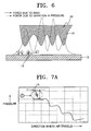
- Figures 5A and 6 are cross-sections of the disk cartridge of Figure 4 taken along line A-A, which theoretically illustrate the principle that flowing of air caused during the rotation of the disk 13 exerts a predetermined force on the surface of the disk by the protrusions 21.
- airflow generated by rotation of the disk 13 repeats compression and expansion while passing between the protrusions 21 of the protrusion group 20 and the disk 13.
- a pressure profile as indicated in a dotted line is formed on the disk 13, and the flow velocity of air becomes faster as air becomes closer to the surface of the disk 13, as indicated in a one-dot-one-dashed line.
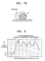
- the influence of the force generated by the flow of air is greater than that of the force generated by the variation in pressure, so that a drag force is exerted at any position in the direction of detaching foreign material from the surface of the disk 13.
- summing of the two forces can accelerate the removal of the foreign materials.
- Figure 8 shows a pattern in which the velocity of air gradually increases while air is being compressed by the protrusions 21, reaches the summit around the apex of each of the protrusions 21 and then decreases a little.
- the disk cartridge 10 when the disk cartridge 10 has a protrusion group 20 formed on the inner wall of the case 12 or shutter 11, it can sufficiently remove foreign materials from the surface of the disk 13 using the flow of air and the difference in pressure generated during the rotation of the disk.
- the protrusion group 20 can be made up of variously-shaped protrusions 21 as shown in Figures 9 and 10.
- Figure 9 shows that n protrusions 21 can have a variety of periodically-repeated shapes obtained by varying a plurality of variables. That is, a protrusion group 20 of Figure 9 can be obtained by adjusting variables such as the distance (D) between the inner wall of the case 12 and the disk 13, the protrusion angles ⁇ 2 and ⁇ 3 of a protrusion 21, the distance (d) between the apex of a protrusion and the disk 13, and the round values r1 and r2 of each protrusion.
- the protrusion group 20 can be linearly disposed in the radial direction of the disk 13 as shown in Figures 4 and 11.
- the protrusion group 20 is divided into several parts, and the parts are arranged in a stepped manner.
- the arrangement of divided protrusion groups 20', 20" and 20"' as shown in Figure 12 in a stepped manner allows foreign materials detached from the surface of the disk 13 to more smoothly slip out of the protrusion groups 20', 20" and 20"'. That is, when the protrusion group 20 is disposed in a straight line as shown in Figure 11, foreign materials detached from the surface of the disk 13 must slip out of many protrusions 21.
- the protrusion group 20 is partitioned into several parts and the parts are arranged in a stepped manner, the foreign materials detached from the surface of the disk 13 slip out of relatively fewer protrusions 21 than the above case, so that the foreign materials can easily slip out of the protrusions.
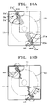
- FIG. 13A is a plan view of a disk cartridge according to a second embodiment of the present invention.
- the principle of removing foreign materials in this embodiment is the same as the above-described first embodiment.
- a protrusion group 20a is not incorporated into or attached to the inner wall of the case 12 but installed as a separate member, which rotates around a rotation axis 20a', so that its position is selected according to mode. That is, the protrusion group 20a is installed so as to rotate around the rotation axis 20a' installed in the case 12, and a lever 20a" is installed so as to protrude outside the case 12.
- the lever 20a" is turned so that the protrusion group 20a is located over and under the disk 13.
- the lever 20a" is turned reversely to the cleaning mode so that the protrusion group 20a is substantially clear of the disk 13. Accordingly, in a cleaning mode, the protrusion group 20a is located over and under the disk, so that the same cleaning effect as that in the first embodiment occurs. In a normal mode, the protrusion group 20a is removed from the region over and under the disk, so that no cleaning effects occur.
- This embodiment is structured so that a user can selectively obtain a cleaning effect made by the protrusion group 20a as desired.
- the protrusion group can adopt a structure in which several protrusion parts are arranged in the radial direction of the disk 13 in a stepped manner as shown in Figure 13B.
- the protrusion group 20a or 20b of Figures 13A or 13B can be disposed at a plurality of positions at an equiangular interval in the direction of rotation of the disk 13.
- Figure 14A is a plan view of a disk cartridge according to a third embodiment of the present invention.
- the third embodiment is almost the same as the second embodiment, except that the protrusion group 20a is not rotated by the manual manipulation of a user but by an automatic driving apparatus such as a solenoid 30.
- the protrusion group 20a can be rotated to desired positions by the driving of the solenoid 30.
- Reference numeral 31 denotes a power and signal connection terminal connected to the solenoid 30.
- the power and signal connection terminal 31 is connected to a corresponding terminal (not shown) formed in a recording/reproducing apparatus when a disk cartridge is inserted into the recording/reproducing apparatus, so that it is provided with power supply and a signal.
- the protrusion group can adopt a shape in which protrusion groups 20b are arranged in a stepped manner in the radial direction of the disk 13 as shown in Figure 14B.
- Protrusion group 20a or 20b shown in Figures 4A or 4B can be disposed at a plurality of places at an equiangular interval in the direction of rotation of the disk 13.
- Figure 15 is a perspective view of a disk cartridge according to a fourth embodiment of the present invention. While the disk cartridges according to the second and third embodiments rotate their corresponding protrusion groups, the disk cartridge according to the fourth embodiment elevates a protrusion group 20c over the disk 13. That is, the protrusion group 20c is installed so that it ascends and descends along a guide rail 40, and approaches or departs the disk 13 by a driving apparatus such as a solenoid 30. Thus, in a cleaning mode, the protrusion group 20c generates a cleaning effect by approaching the disk 13. In a normal mode, the protrusion group 20c is isolated from the disk 13 to prevent variations in flow velocity and pressure from being caused by the protrusions.
- the protrusion group 20c can adopt a structure in which several protrusion groups are arranged in the radial direction of the disk 13 in a stepped manner as shown in Figure 14B.
- the protrusion group 20c can be disposed at a plurality of positions at an equiangular interval in the direction of rotation of the disk 13.
- a disk cartridge according to the present invention can be modified into various shapes as the aforementioned embodiments.
- the protrusion group is installed in the housing of a recording/reproducing apparatus including a turntable on which a disk is seated. That is, since the housing is the same as the disk cartridge in that it surrounds a disk, if the housing also has various shapes of protrusion groups protruding toward the disk as described above, forces generated by the flow of air and a pressure variation are exerted on the surface of the disk, like when a disk rotates within a cartridge.
- FIG 16A is a plan view of a disk recording/reproducing apparatus according to a first embodiment of the present invention adopting a protrusion group.
- This embodiment is similar to the above-described third embodiment of a disk cartridge.
- a protrusion group 20d is rotatably installed within a housing 50 and rotated by a driving apparatus such as a solenoid 30.
- a driving apparatus such as a solenoid 30.
- the protrusion group 20a is rotated and located over and under the disk 13, such that a cleaning effect is generated by the flow of air caused during the rotation of the disk 13.
- the protrusion group 20d gets out of the region over and under the disk 13 so that it does not affect the surface of the disk 13.
- the protrusion group can adopt a structure in which several protrusion groups 20e are arranged in the radial direction of the disk 13 in a stepped manner as shown in Figure 16B.
- the protrusion group 20d or 20e of Figures 16A or 16B can be disposed at a plurality of positions at an equiangular interval in the direction of rotation of the disk 13.
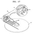
- FIG 17 is a perspective view of a disk recording/reproducing apparatus according to a second embodiment of the present invention.
- the second embodiment is similar to the above-described forth embodiment of a disk cartridge.
- a protrusion group 20f is installed within a housing 50 so that it ascends and descends along a guide rail 51, and approaches or departs the disk 13 by a driving apparatus such as a solenoid 30.
- a driving apparatus such as a solenoid 30.
- the protrusion group 20f in a cleaning mode, the protrusion group 20f generates a cleaning effect by approaching the disk 13.
- the protrusion group 20f is isolated from the disk 13 to prevent variations in flow velocity and pressure from being caused by the protrusions.
- the protrusion group 20f can adopt a structure in which several protrusion groups are arranged in the radial direction of the disk 13 in a stepped manner as shown in Figure 16B.
- the protrusion group 20f can be disposed at a plurality of positions at an equiangular interval in the direction of rotation of the disk 13.
- a protrusion group is formed within the cartridge or the housing of the disk recording/reproducing apparatus so as to face the disk, such that forces generated by the flow of air and a pressure variation are exerted on the surface of the disk during the rotation of the disk. Therefore, foreign materials can be effectively removed from the surface of the disk without a separate cleaning apparatus.
Landscapes
- Feeding And Guiding Record Carriers (AREA)
- Optical Record Carriers And Manufacture Thereof (AREA)
Abstract
Description
Claims (35)
- A disk cartridge (10) including a case (12) for housing an information recording/reproducing disk (13) and a shutter (11) which is installed within the case (12) and selectively opened and closed to accomplish an access of the disk (13) to a recording/reproducing apparatus, wherein a protrusion group (20) having a plurality of protrusions (21) each protruding toward the disk (13) is formed on an inner wall of at least one of the case (12) and the shutter (11).
- The disk cartridge of claim 1, wherein the protrusion group (20) has a structure in which the plurality of protrusions (21) repeat at a predetermined interval in a predetermined pattern.
- The disk cartridge of claim 1 or 2, wherein each of the protrusions is arranged to lie in a radial direction of the disk (13).
- The disk cartridge of claim 1, 2 or 3 wherein the protrusion group (20) is disposed at a plurality of places at an equiangular interval in the direction of the rotation of the disk.
- The disk cartridge of claim 1, wherein the protrusion group has a structure in which protrusion groups (21) are arranged in a stepped manner in the radial direction of the disk.
- A disk cartridge (10) including a case (12) for housing an information recording/reproducing disk (13) and a shutter (11) which is installed within the case and selectively opened and closed to accomplish an access of the disk to a recording/reproducing apparatus, wherein a protrusion group (20) having a plurality of protrusions each protruding toward the disk is rotatably located within the case so that the protrusions are located over and under the disk or removed from the region over and under the disk.
- The disk cartridge of claim 6, further comprising a driving apparatus (30) for rotating the protrusion group.
- The disk cartridge of claim 6 or 7, wherein the protrusion group (20) has a structure in which the plurality of protrusions (21) repeat at a predetermined interval in a predetermined pattern.
- The disk cartridge of claim 6, 7 or 8 wherein each of the protrusions (21) lie in the radial direction of the disk.
- The disk cartridge of claim 6, 7, 8 or 9 wherein the protrusion group (20) is disposed at a plurality of places at an equiangular interval in the direction of the rotation of the disk.
- The disk cartridge of claim 6, 7, 8, 9 or 10 wherein the protrusion group (20) has a structure in which protrusion groups are arranged in a stepped manner in the radial direction of the disk.
- A disk cartridge (10) including a case (12) for housing an information recording/reproducing disk (13) and a shutter (11) which is installed within the case and selectively opened and closed to accomplish an access of the disk to a recording/reproducing apparatus, wherein a protrusion group (20) having a plurality of protrusions (21) each protruding toward the disk is formed within the case so as to ascend or descend, such that the protrusions approach to the disk or are isolated from the disk.
- The disk cartridge of claim 12, further comprising a driving apparatus (30) for elevating the protrusion group.
- The disk cartridge of claim 12 or 13, wherein the protrusion group (20) has a structure in which the plurality of protrusions (21) repeat at a predetermined interval in a predetermined pattern.
- The disk cartridge of claim 12, 13 or 14 wherein each of the protrusions (21) lies in the radial direction of the disk.
- The disk cartridge of claim 12, 13, 14 or 15 wherein the protrusion group (20) is disposed at a plurality of places at an equiangular interval in the direction of the rotation of the disk.
- The disk cartridge of claim 12, 13, 14, 15 or 16 wherein the protrusion group (20) has a structure in which protrusion groups (20) are arranged in a stepped manner in the radial direction of the disk.
- A disk recording/reproducing apparatus for recording information on or reproducing information from a disk (13) while rotating the disk loaded within a housing (12), wherein a protrusion group (20) having a plurality of protrusions (21) each protruding toward the disk is rotatably formed within the housing so that the protrusions are located over and under the disk or removed from the region over and under the disk.
- The disk recording/reproducing apparatus of claim 18, further comprising a driving apparatus (30) for rotating the protrusion group (20).
- The disk recording/reproducing apparatus of claim 18 or 19 wherein the protrusion group (20) has a structure in which the plurality of protrusions (21) repeat at a predetermined interval in a predetermined pattern.
- The disk recording/reproducing apparatus of claim 18, 19 or 20 wherein each of the protrusions (21) lies in the radial direction of the disk.
- The recording/reproducing apparatus of claim 18, 19, 20 or 21 wherein the protrusion group (20) is disposed at a plurality of places at an equiangular interval in the direction of the rotation of the disk (13).
- The disk recording/reproducing apparatus of claim 18, 19, 20, 21 or 22 wherein the protrusion group (20) has a structure in which protrusion groups (20) are arranged in a stepped manner in the radial direction of the disk.
- A disk recording/reproducing apparatus for recording information on or reproducing information from a disk (13) while rotating the disk loaded within a housing (12), wherein a protrusion group (20) having a plurality of protrusions (21) each protruding toward the disk is formed within the housing (12) so as to ascend or descend, such that the protrusions (21) approach to the disk or are isolated from the disk.
- The disk recording/reproducing apparatus of claim 24, further comprising a driving apparatus (30) for elevating the protrusion group.
- The disk recording/reproducing apparatus of claim 24 or 25 wherein the protrusion group (20) has a structure in which the plurality of protrusions repeat at a predetermined interval in a predetermined pattern.
- The disk recording/reproducing apparatus of claim 24, 25 or 26 wherein each of the protrusions (21) lies in the radial direction of the disk.
- The disk recording/reproducing apparatus of claim 24, 25, 26 or 27 wherein the protrusion group (20) is disposed at a plurality of places at an equiangular interval in the direction of the rotation of the disk.
- The disk recording/reproducing apparatus of claim 24, 25, 26, 27 or 28 wherein the protrusion group has a structure in which protrusion groups (20) are arranged in a stepped manner in the radial direction of the disk.
- A cleaning apparatus for use with a rotatable information recording disk (13), the apparatus comprising a protrusion group (20) having a plurality of protrusions (21) each protruding toward the disk (13).
- The cleaning apparatus of claim 30, wherein the protrusion group (20) is fixedly mounted in relation to the rotatable disk (13).
- The cleaning apparatus of claim 31, wherein the protrusion group (20) is formed on an inner wall of a case (12) or a shutter (11) of a disk cartridge (10).
- The cleaning apparatus of claim 30, wherein the protrusion group (20) is moveably mounted with respect to the rotatable disk (13).
- The cleaning apparatus of claim 33, wherein the protrusion group (20) is rotatable toward or away from the disk (13).
- The cleaning apparatus of claim 33, wherein the protrusion group (20) ascends or descends toward or away from the disk (13).
Applications Claiming Priority (2)
| Application Number | Priority Date | Filing Date | Title |
|---|---|---|---|
| KR2001008997 | 2001-02-22 | ||
| KR10-2001-0008997A KR100389864B1 (en) | 2001-02-22 | 2001-02-22 | Disk cartridge and disk recording/reproducing apparatus |
Publications (3)
| Publication Number | Publication Date |
|---|---|
| EP1239466A2 true EP1239466A2 (en) | 2002-09-11 |
| EP1239466A3 EP1239466A3 (en) | 2003-04-02 |
| EP1239466B1 EP1239466B1 (en) | 2005-12-21 |
Family
ID=19706125
Family Applications (1)
| Application Number | Title | Priority Date | Filing Date |
|---|---|---|---|
| EP01304638A Expired - Lifetime EP1239466B1 (en) | 2001-02-22 | 2001-05-25 | Disk cartridge and disk recording / reproducing apparatus |
Country Status (6)
| Country | Link |
|---|---|
| US (1) | US7069570B2 (en) |
| EP (1) | EP1239466B1 (en) |
| KR (1) | KR100389864B1 (en) |
| CN (1) | CN1248232C (en) |
| DE (1) | DE60116045T2 (en) |
| TW (1) | TW544661B (en) |
Families Citing this family (4)
| Publication number | Priority date | Publication date | Assignee | Title |
|---|---|---|---|---|
| KR100459713B1 (en) * | 2002-05-03 | 2004-12-03 | 삼성전자주식회사 | Filtering apparatus for hard disk drive |
| KR100518578B1 (en) | 2003-05-26 | 2005-10-04 | 삼성전자주식회사 | Particle remover for data storage device and ramp having the same |
| JP4004442B2 (en) * | 2003-08-29 | 2007-11-07 | シナノケンシ株式会社 | Disk drive device |
| KR100564612B1 (en) * | 2004-02-19 | 2006-03-28 | 삼성전자주식회사 | Hard disk drive |
Family Cites Families (21)
| Publication number | Priority date | Publication date | Assignee | Title |
|---|---|---|---|---|
| US3893185A (en) * | 1973-07-16 | 1975-07-01 | John J Ring | Fluid biased head assembly |
| US3839734A (en) * | 1973-08-27 | 1974-10-01 | Ibm | Air turbulence utilized to clear disc |
| US4626949A (en) * | 1983-05-19 | 1986-12-02 | Verbatim Corporation | Magnetic record disk cleaning and stabilizing assembly |
| US4648002A (en) * | 1984-10-12 | 1987-03-03 | Verbatim Corporation | Wiping system for magnetic recording disks |
| KR950000954B1 (en) * | 1985-05-20 | 1995-02-06 | 히다찌마구세루 가부시기가이샤 | Disc cartridge |
| US4843511A (en) * | 1985-09-27 | 1989-06-27 | Polaroid Corporation | Magnetic disk cassette having internal biasing ribs |
| JPS6472375A (en) * | 1987-09-14 | 1989-03-17 | Hitachi Maxell | Disk cartridge |
| US4885652A (en) * | 1988-07-11 | 1989-12-05 | Minnesota Mining And Manufacturing Company | Disk cartridge |
| JPH02162563A (en) * | 1988-12-16 | 1990-06-22 | Victor Co Of Japan Ltd | Stable rotating device for flexible recording medium disk |
| JPH0380489A (en) * | 1989-08-23 | 1991-04-05 | Nec Corp | Optical disk cartridge |
| JPH04159676A (en) * | 1990-10-23 | 1992-06-02 | Ricoh Co Ltd | disc cartridge |
| US5218503A (en) * | 1991-10-18 | 1993-06-08 | Syquest Technology, Inc. | 31/2 inch removable cartridge for a disk drive |
| US5537281A (en) * | 1994-10-18 | 1996-07-16 | Iomega Corporation | Flexible disk cartridge having disk stabilization means |
| JPH08221930A (en) * | 1995-02-17 | 1996-08-30 | Fuji Photo Film Co Ltd | Magnetic disk cartridge and its production |
| US5812351A (en) * | 1995-09-15 | 1998-09-22 | Imation Corp. | Raised-region having sloped edges under cleaning fabric in flexible magnetic recording diskette cartridge cover shell |
| JPH09282835A (en) * | 1996-04-17 | 1997-10-31 | Fuji Photo Film Co Ltd | Magnetic disk cartridge |
| US5980791A (en) * | 1996-07-17 | 1999-11-09 | Imation Corp. | Method for forming a molded-in lifter for cleaning a flexible magnetic disc |
| JPH10320955A (en) * | 1997-05-20 | 1998-12-04 | Sony Corp | Disk cartridge |
| KR100288914B1 (en) * | 1997-12-02 | 2001-05-02 | 구자홍 | Cartridge of information recording / playback medium |
| KR20000009758A (en) * | 1998-07-28 | 2000-02-15 | 윤종용 | Noise and vibration attenuation device of rotation actuator |
| WO2000011673A1 (en) * | 1998-08-24 | 2000-03-02 | Sony Corporation | Disk cartridge |
-
2001
- 2001-02-22 KR KR10-2001-0008997A patent/KR100389864B1/en not_active Expired - Fee Related
- 2001-05-16 TW TW090111683A patent/TW544661B/en not_active IP Right Cessation
- 2001-05-25 DE DE60116045T patent/DE60116045T2/en not_active Expired - Fee Related
- 2001-05-25 EP EP01304638A patent/EP1239466B1/en not_active Expired - Lifetime
- 2001-05-30 CN CNB011208139A patent/CN1248232C/en not_active Expired - Fee Related
- 2001-06-20 US US09/884,421 patent/US7069570B2/en not_active Expired - Fee Related
Also Published As
| Publication number | Publication date |
|---|---|
| DE60116045T2 (en) | 2006-06-29 |
| KR100389864B1 (en) | 2003-07-04 |
| CN1248232C (en) | 2006-03-29 |
| DE60116045D1 (en) | 2006-01-26 |
| US7069570B2 (en) | 2006-06-27 |
| KR20020068744A (en) | 2002-08-28 |
| EP1239466A3 (en) | 2003-04-02 |
| CN1372265A (en) | 2002-10-02 |
| US20020114267A1 (en) | 2002-08-22 |
| TW544661B (en) | 2003-08-01 |
| EP1239466B1 (en) | 2005-12-21 |
Similar Documents
| Publication | Publication Date | Title |
|---|---|---|
| JPH10289489A5 (en) | ||
| EP1474801B1 (en) | Disc cartridge | |
| US20060014053A1 (en) | Magnetic disk and magnetic disk device provided with the same | |
| KR100483103B1 (en) | Magnetic disk apparatus and its servo signal recording method | |
| EP1239466A2 (en) | Disk cartridge and disk recording / reproducing apparatus | |
| US7069564B2 (en) | Disk apparatus | |
| JPH0817159A (en) | Disk cartridge | |
| US20050120365A1 (en) | Disc cartridge | |
| CN1200533A (en) | cartridge | |
| CN1412768A (en) | Disk cassette | |
| US20060139805A1 (en) | Magnetic disk and magnetic disk apparatus provided with the same | |
| EP1792311A1 (en) | Turntable device for spin-coating | |
| CN1034450C (en) | Disc cartridge | |
| TWI267849B (en) | Apparatus for attaching and detaching cap for optical disc spin-coating, apparatus for optical disc spin-coating comprising the same, method of manufacturing optical disc using the apparatus for attaching and detaching cap for optical disc spin-coating | |
| EP1267351A2 (en) | Disc cartridge | |
| JP2936169B2 (en) | Disk cartridge | |
| CN1249719C (en) | Box type disk and driving device thereof | |
| CN100380510C (en) | Disk case | |
| EP1548738A1 (en) | Disc cartridge | |
| US7434241B2 (en) | Recording and reproducing apparatus of thin optical disc | |
| US6295182B1 (en) | Disc cartridge | |
| EP1605444A2 (en) | Positioning device | |
| JP4283865B2 (en) | Disk unit | |
| KR100652389B1 (en) | Bracket Structure for Hard Disk Drives | |
| US20020003682A1 (en) | Magnetic disc unit |
Legal Events
| Date | Code | Title | Description |
|---|---|---|---|
| PUAI | Public reference made under article 153(3) epc to a published international application that has entered the european phase |
Free format text: ORIGINAL CODE: 0009012 |
|
| 17P | Request for examination filed |
Effective date: 20010608 |
|
| AK | Designated contracting states |
Kind code of ref document: A2 Designated state(s): AT BE CH CY DE DK ES FI FR GB GR IE IT LI LU MC NL PT SE TR |
|
| AX | Request for extension of the european patent |
Free format text: AL;LT;LV;MK;RO;SI |
|
| PUAL | Search report despatched |
Free format text: ORIGINAL CODE: 0009013 |
|
| AK | Designated contracting states |
Designated state(s): AT BE CH CY DE DK ES FI FR GB GR IE IT LI LU MC NL PT SE TR Kind code of ref document: A3 Designated state(s): AT BE CH CY DE DK ES FI FR GB GR IE IT LI LU MC NL PT SE TR |
|
| AX | Request for extension of the european patent |
Extension state: AL LT LV MK RO SI |
|
| RIC1 | Information provided on ipc code assigned before grant |
Ipc: 7G 11B 23/50 A |
|
| AKX | Designation fees paid |
Designated state(s): DE FR GB |
|
| 17Q | First examination report despatched |
Effective date: 20041209 |
|
| GRAP | Despatch of communication of intention to grant a patent |
Free format text: ORIGINAL CODE: EPIDOSNIGR1 |
|
| GRAS | Grant fee paid |
Free format text: ORIGINAL CODE: EPIDOSNIGR3 |
|
| GRAA | (expected) grant |
Free format text: ORIGINAL CODE: 0009210 |
|
| AK | Designated contracting states |
Kind code of ref document: B1 Designated state(s): DE FR GB |
|
| REG | Reference to a national code |
Ref country code: GB Ref legal event code: FG4D |
|
| REF | Corresponds to: |
Ref document number: 60116045 Country of ref document: DE Date of ref document: 20060126 Kind code of ref document: P |
|
| ET | Fr: translation filed | ||
| PLBE | No opposition filed within time limit |
Free format text: ORIGINAL CODE: 0009261 |
|
| STAA | Information on the status of an ep patent application or granted ep patent |
Free format text: STATUS: NO OPPOSITION FILED WITHIN TIME LIMIT |
|
| 26N | No opposition filed |
Effective date: 20060922 |
|
| PGFP | Annual fee paid to national office [announced via postgrant information from national office to epo] |
Ref country code: DE Payment date: 20080529 Year of fee payment: 8 |
|
| PGFP | Annual fee paid to national office [announced via postgrant information from national office to epo] |
Ref country code: GB Payment date: 20080528 Year of fee payment: 8 |
|
| GBPC | Gb: european patent ceased through non-payment of renewal fee |
Effective date: 20090525 |
|
| REG | Reference to a national code |
Ref country code: FR Ref legal event code: ST Effective date: 20100129 |
|
| PG25 | Lapsed in a contracting state [announced via postgrant information from national office to epo] |
Ref country code: FR Free format text: LAPSE BECAUSE OF NON-PAYMENT OF DUE FEES Effective date: 20090602 |
|
| PGFP | Annual fee paid to national office [announced via postgrant information from national office to epo] |
Ref country code: FR Payment date: 20080514 Year of fee payment: 8 |
|
| PG25 | Lapsed in a contracting state [announced via postgrant information from national office to epo] |
Ref country code: GB Free format text: LAPSE BECAUSE OF NON-PAYMENT OF DUE FEES Effective date: 20090525 |
|
| PG25 | Lapsed in a contracting state [announced via postgrant information from national office to epo] |
Ref country code: DE Free format text: LAPSE BECAUSE OF NON-PAYMENT OF DUE FEES Effective date: 20091201 |