EP1239396A2 - Method and system for an user interface for a medical diagnostic imaging device - Google Patents
Method and system for an user interface for a medical diagnostic imaging device Download PDFInfo
- Publication number
- EP1239396A2 EP1239396A2 EP01310622A EP01310622A EP1239396A2 EP 1239396 A2 EP1239396 A2 EP 1239396A2 EP 01310622 A EP01310622 A EP 01310622A EP 01310622 A EP01310622 A EP 01310622A EP 1239396 A2 EP1239396 A2 EP 1239396A2
- Authority
- EP
- European Patent Office
- Prior art keywords
- function
- activation area
- processor
- touchscreen
- activation
- Prior art date
- Legal status (The legal status is an assumption and is not a legal conclusion. Google has not performed a legal analysis and makes no representation as to the accuracy of the status listed.)
- Ceased
Links
Images


Classifications
-
- A—HUMAN NECESSITIES
- A61—MEDICAL OR VETERINARY SCIENCE; HYGIENE
- A61B—DIAGNOSIS; SURGERY; IDENTIFICATION
- A61B6/00—Apparatus or devices for radiation diagnosis; Apparatus or devices for radiation diagnosis combined with radiation therapy equipment
- A61B6/46—Arrangements for interfacing with the operator or the patient
- A61B6/461—Displaying means of special interest
- A61B6/465—Displaying means of special interest adapted to display user selection data, e.g. graphical user interface, icons or menus
-
- A—HUMAN NECESSITIES
- A61—MEDICAL OR VETERINARY SCIENCE; HYGIENE
- A61B—DIAGNOSIS; SURGERY; IDENTIFICATION
- A61B5/00—Measuring for diagnostic purposes; Identification of persons
-
- A—HUMAN NECESSITIES
- A61—MEDICAL OR VETERINARY SCIENCE; HYGIENE
- A61B—DIAGNOSIS; SURGERY; IDENTIFICATION
- A61B5/00—Measuring for diagnostic purposes; Identification of persons
- A61B5/74—Details of notification to user or communication with user or patient; User input means
- A61B5/742—Details of notification to user or communication with user or patient; User input means using visual displays
- A61B5/7435—Displaying user selection data, e.g. icons in a graphical user interface
-
- A—HUMAN NECESSITIES
- A61—MEDICAL OR VETERINARY SCIENCE; HYGIENE
- A61B—DIAGNOSIS; SURGERY; IDENTIFICATION
- A61B6/00—Apparatus or devices for radiation diagnosis; Apparatus or devices for radiation diagnosis combined with radiation therapy equipment
-
- A—HUMAN NECESSITIES
- A61—MEDICAL OR VETERINARY SCIENCE; HYGIENE
- A61B—DIAGNOSIS; SURGERY; IDENTIFICATION
- A61B8/00—Diagnosis using ultrasonic, sonic or infrasonic waves
-
- A—HUMAN NECESSITIES
- A61—MEDICAL OR VETERINARY SCIENCE; HYGIENE
- A61B—DIAGNOSIS; SURGERY; IDENTIFICATION
- A61B8/00—Diagnosis using ultrasonic, sonic or infrasonic waves
- A61B8/46—Ultrasonic, sonic or infrasonic diagnostic devices with special arrangements for interfacing with the operator or the patient
- A61B8/461—Displaying means of special interest
- A61B8/465—Displaying means of special interest adapted to display user selection data, e.g. icons or menus
-
- A—HUMAN NECESSITIES
- A61—MEDICAL OR VETERINARY SCIENCE; HYGIENE
- A61B—DIAGNOSIS; SURGERY; IDENTIFICATION
- A61B5/00—Measuring for diagnostic purposes; Identification of persons
- A61B5/74—Details of notification to user or communication with user or patient; User input means
- A61B5/7475—User input or interface means, e.g. keyboard, pointing device, joystick
Definitions
- the present invention relates to medical diagnostic imaging systems.
- the present invention relates to a user interface for a medical diagnostic imaging device.
- an ultrasound imaging system may include 2D or 3D imaging, Doppler overlay, Colorflow scans, image frame recording and playback capabilities, image annotation and archiving, zoom, panning, and the like.
- the number and complexity of the device functions performed by medical diagnostic imaging system have increased to the point where many such peripheral devices include a full-sized keyboard and trackball as part of the user interface.
- the peripheral devices increase the cost, complexity, and space required by the medical diagnostic imaging system.
- the keyboard for example, is similar to that used on a home computer, and is required to direct the operation of the medical diagnostic imaging system. Doctors and technicians, however, are not computer scientists. In other words, the valuable time spent trying to understand and operate the peripheral devices of a medical diagnostic imaging system is better spent actually using the device to help a patient.
- a preferred embodiment of the present invention provides, in a medical diagnostic device, an operator interface for providing operator control over device functions of the medical diagnostic device.
- the operator interface includes a monitor for producing an image display, a touchscreen disposed in front of the monitor, and a plurality of activation areas defined on the image display.
- Each device function in a device function set that implements a preselected medical diagnostic device is associated with at least one of the activation areas so that no external input other than that supported by the touchscreen is required to operate the medical diagnostic device.
- a processor is coupled to the touch screen for detecting a touch on the touchscreen that identifies a selected activation area. The processor then performs the device function associated with the selected activation area.
- a preferred embodiment of the present invention further provides a method for providing operator control over a medical diagnostic device.
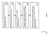
- the method includes the steps of assigning each device function in a preselected device function set that implements a preselected medical diagnostic device to at least one function activation area on an image display. Subsequently, the method monitors a touchscreen for a touch, and determines a selected activation area based on the touch and the function activation area. Once the selected activation area is determined, the method performs a device function associated with the selected activation area.
- the medical imaging system 100 includes an electromechanical subsystem 102 which implements the electronic and mechanical subsystems of a medical imaging system apart from the computer software, monitor, and touchscreen interface discussed below.
- the electromechanical subsystem 102 may incorporate, for example, mechanical motor servos and feedback sensors 104, a magnet, X-ray image detectors, or an Acoustic Power Unit (APU) 106 coupled to an ultrasound scanner 108.
- the medical imaging system 100 may be implemented as any desired diagnostic system, including an MRI system, X-ray system, ultrasound system, electron microscope, heart monitor system, and the like.
- a system computer 110 that includes an electromechanical subsystem interface 112, a processor 114, and a memory 116.
- the memory 116 stores instructions for execution by the processor 114.
- a touchscreen 120 couples to the processor 114 and, in conjunction with the functional modules, provides complete control over the medical imaging system 100. In other words, no additional external input is required from, for example, a touchscreen, a trackball, function keys, and the like.
- the touchscreen 120 may be implemented as a resistive, capacitive, or other touchscreen that provides an indication to the processor 114 that an operator has touched the touchscreen 120 and a location of the touch.
- the memory 116 stores instructions that implement the device functions of the functional modules of a preselected medical imaging system (e.g., an ultrasound imaging system).
- a preselected medical imaging system e.g., an ultrasound imaging system.
- Such modules include a systems operation module, a report module, an archiving module, an image processing module, a measurement module, and a beamforming module, as examples. Additional functional modules are discussed below in conjunction with Figure 2.
- the functional modules 200 implement one or more device functions and include a system operation module 202, report module 204, archiving module 206, image processing module 208, beamforming module 210, scanning module 212, acquisition module 214, user interface module 216, signal processing module 218, scan conversion module 220, presentation module 222, measurement and analysis module 224, and a diagnostic system configuration and maintenance module 226.
- the functional modules 200 include modules that may be used to implement, for example, an ultrasound diagnostic system. Certain functional modules may operate independently of other functional modules.
- Some functional modules may pass intermediate results or partially processed data to other functional modules for further processing.
- the functional modules noted above are exemplary only. In other words, additional functional modules may be added for other any other tasks to be performed by a given medical diagnostic system, such as an external communication module.
- the system operation module 202 carries out system control functions.
- the system operation module 202 may include device functions to directly control the electromechanical subsystem 102 to drive motor servos, evaluate sensor feedback, and initiate and terminate an ultrasound imaging sequence.
- the report module 204 executes patient reporting device functions.
- the patient reporting device functions may include, for example, querying of patient images from the archiving module 206, and preparation, display, and printing of patient examination records, billing records, and patient contact information.
- the archiving module 206 is responsible for device functions that maintain database records related to the operation of the diagnostic system.
- the database records may include patient examination images (either static images or image sequences (e.g., MPEG2 or other compressed or non-compressed movies)), operation and maintenance statistics (e.g., the time, date, and examination type for each use of the diagnostic system, and its service history), patient contact, billing, and examination records, including physician diagnoses, and the like.
- the image-processing module 208 is responsible for device functions associated with manipulation of images (still or video) generated by the diagnostic system.
- the image-processing module may provide image contrast enhancement, image cropping, resolution enhancement, and other image processing functions.
- the image-processing module 208 typically allows the operator to retrieve, examine, modify, print, and save processed images, for example, by communicating with the database maintained by the archiving module 206.
- the image-processing module may also perform volume rendering to construct 3-dimensional models from a series of 2-dimensional B-mode or Doppler data sets of images using known volume rendering techniques.
- the beamforming module 210 is responsible, for example, for device functions for controlling beamforming required to generate images in an ultrasound imaging system.
- the beamforming module 210 may receive raw data representing ultrasound echo information, apply the appropriate steering and gain corrections to the raw data, and output processed data sets ready for scan conversion for display as B-mode, Doppler, colorflow, or other image types.
- the scanning module 212 handles user interface events received from the user interface module 216, determines the mode of an ultrasound scan to be taken, and passes the appropriate scan parameters to the acquisition module 214.
- the acquisition module 214 device functions handle requests for scan parameter changes, implements the scan parameter changes, and translates scan parameters if required by the hardware with the ultrasound scanner 108.
- the acquisition module 214 executes scan sequences in the operator selected manner, and transfers hardware events (e.g., overpower, scanner disconnect, and the like), for example, to the system operation module 202 for error handling.
- the acquisition module 214 also receives ultrasound data sets that have been collected and formed by the beamforming module 210 and relays the data sets to the presentation module 222.
- the user interface module 216 implements, preferably, functional menus, displays scan parameters, and monitors operator interface hardware, including keyboard control panels and trackballs (if included).
- the user interface module 216 handles device functions such as displaying and moving images and text and delegating touchscreen events, menu events, keyboard panel events, and trackball events to the scanning module 212 and other modules.
- an image processing function menu may be displayed that allows the user to increase brightness, decrease brightness, increase contrast, decrease contrast, and the like.
- the signal-processing module 218 provides those device functions for processing of data sets acquired from the electromechanical subsystem 102 based upon the current mode of operation.
- the signal-processing module 218 may, for example, perform vector processing, including Doppler and Color Flow processing on the data sets.
- the scan conversion module 220 device functions convert data between coordinate systems.
- the scan conversion module 220 may convert data sets in the polar coordinate system to the Cartesian coordinate system for ready display on a typical video monitor.
- the presentation module 222 device functions process and display ultrasound image information, including static images, video images, traces, and the like.
- the presentation module 222 is preferably adapted to display, additionally, Doppler and Color Flow images.
- the measurement and analysis (M&A) module 224 provides device functions to implement an interface that allows the operator to examine the data returned during patient examination.
- the M&A module may allow the operator to determine blood flow velocity, perform volume measurements, perform 2-dimensional measurements such as determining cross sectional area and blood vessel diameter, perform cardiology or radiology analyses (e.g., locating of heart defects or tumors), increasing or decreasing scan depth of ultrasound focus, moving a Region of Interest box, positioning a Doppler gate, changing focus location, and the like.
- the diagnostic system configuration and maintenance (C&M) module 226 is responsible for interfacing with the archiving module 206 to track maintenance history for the diagnostic system.
- the C&M module 226 preferably allows a technician to enter the results of routine or non-routine maintenance calls, allow operators to submit maintenance requests, and the like.
- the C&M module also allows an operator to perform initial setup and configuration operations on the diagnostic system.
- a voice recognition module (not shown) may also be provided to allow the medical imaging system 100 to respond to operator voice input.
- the functional modules 200 may be selected to implement any desired medical diagnostic system.
- the functional modules 200 are chosen to implement a complete device function set for an ultrasound system, and therefore include functional modules specifically directed to ultrasound imaging, for example, the beamforming module 210, scanning module 212, and scan conversion module 220.
- the device function set differs between diagnostic systems, however.
- an X-ray imaging system may include a linear tomographic scan control module, rather than a beamforming module, and a servo motor system used to move an X-ray source.
- any device function set may be used by determining which functional modules to include in the device function set for a given diagnostic system.
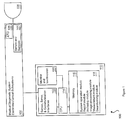
- FIG 3 that figure shows an ultrasound system monitor 300 with touchscreen 302.
- the touchscreen 302 is positioned in front of the monitor 300 that presents an image display of graphics and text associated with operation of the imaging system 100, including B-mode images, Doppler images, text labels, and the like. Numerous activation areas and pop up menus are defined on the image display, including a penetration depth increase activation area 304 and a penetration depth decrease activation area 306.
- a drag indicator 308 illustrates the operation of touching the touchscreen 302 and dragging a finger, pen, or other pointer in the direction of the drag indicator 308.
- Additional activation areas include the zoom activation area 310, the store image activation area 312, ad the movement activation area 314.
- a brightness control activation area 316, a contrast control activation area 318, an image rotate activation area 320, and an image print activation area 322 are also defined.
- Figure 3 shows a blood flow measurement activation area 324, and a mode select activation area 326.
- the activation areas may be defined in location and size as absolute pixel regions on the display.
- the zoom activation area 310 may defined as a rectangle of 100 pixels by 50 pixels centered at pixel 0, 400.
- the zoom activation area 310 (as well as the brightness and contrast activation areas 316 and 318) may be divided into two sections, one for increased zoom (e.g., shown as an up-arrow) and one for decreased zoom (e.g., shown as a down-arrow).
- the activation areas may be defined relative to one another in position and size.
- the activation areas need not be rectangular. Rather, the activation areas may be circular, elliptical, and the like.
- the penetration depth increase activation area 304 and the penetration depth decrease activation area 306 allow the operator to perform the device functions of increasing or decreasing the penetration depth of ultrasound energy into the body.
- the processor 114 identifies the penetration depth increase activation area 304 as a selected function activation area, and increases the penetration depth of transmitted ultrasound energy.
- the processor 114 increases or decreases the zoom level appropriately.
- Each device function in a device function set that implements the medical imaging system 100 is associated with at least one of the function activation areas or pop up menus.
- the activation areas and pop up menus cover all of the device functions implemented by the medical imaging system 100.
- the touchscreen 302 alone may be used to control the medical imaging system 100 in its entirety and no additional input from other sources (e.g., a keyboard or trackball) is required to operate the medical imaging system 100.
- the store image activation area 312 allows the operator to perform the device functions of storing the current image in an archive
- the brightness and contrast activation areas 316 and 318 allow operator manipulation of brightness and contrast
- the movement activation area 314 allows the operator to perform the device functions of moving a cursor, ROI box, image, or text label in any direction as indicated by the specific directional activation areas associated with the movement activation area 314.
- the processor 114 identifies as selected function activation areas (when touched) the image rotate activation area 320 (e.g., to rotate an image ninety degrees), the image print activation area 322 (e.g., to print the image to an attached or network printer), and the measurement activation area 324 (e.g., to begin displaying measurements of blood flow velocity, volume, and the like).
- the mode select activation area 326 may be used to select a particular imaging mode for the medical imaging system 100.
- the mode select activation area 326 may be used to select in a cyclic manner through repeating touches B-mode, M-mode, B-mode plus Doppler, B-mode plus colorflow imaging modes, and the like.
- the processor 114 may present pop up function menus to the operator on the monitor 300.
- the processor may present the pop up mode selection menu 328.
- the mode selection menu 328 as illustrated includes the following function menu activation areas: a B-mode activation area 330, an M-mode activation area 332, and a B-mode plus Doppler activation area 334.
- the operator touches an appropriate activation area 330-334 to choose an imaging mode.
- pop up function menus with individual activation areas for mode specific functions may also be implemented for any number of device functions (e.g., measurement and analysis and calibration device functions) and displayed when the operator touches a predetermined pop up menu location on the monitor 300, or in response to a previous touchscreen menu selection.
- device functions e.g., measurement and analysis and calibration device functions
- the processor 114 allows the user to drag images and text as indicated by the drag indicator 308.
- the operator may place a text label on the display by dragging it using the touchscreen 302.
- the medical imaging system 100 may display a keyboard image on the monitor 300 with each keyboard key defined by a rectangular box or pixel area.
- the user may type on the screen using a soft-keyboard, rather than resort to a separate physical keyboard.
- the medial imaging system 100 includes character recognition software that allows the operator to use a finger, pen, or other pointer on the touchscreen to enter characters.
- a vertical drag on the touchscreen may be interpreted as the letter 'l', while a cross on the touchscreen may be interpreted as the letter 't', and the like.
- activation areas described above are exemplary only, and that many other arrangements and designs of activation areas, pop up controls, pop up menus, and the like are also suitable.
- the touchscreen 302 provides an enhanced degree of interactivity with the images and text displayed on the monitor 300.
- a drag operation e.g., as shown by the drag indicator 308
- the processor 114 may interpret touches on the touchscreen 302 to select one or more simultaneously displayed windows as "active" (i.e., to direct the processor to continue to update or to freeze updates of a Doppler or 2D display window), to set scan depths, to change focus location, and the like.
- the operator may alternate between, for example, simultaneous 2D, Colorflow, Doppler, and zoom modes using the touchscreen to make any of the modes active, and to set the appropriate ROI active for size and location changes.
- the processor 114 tracks the current operational mode of the medical imaging system 100.
- the processor may pop up one or more menus appropriate for the current operational mode (e.g., a Doppler function menu or B-mode function menu that include the functions of interest in the current operational mode).
- the processor 114 may display mode specific pop up controls for such features as a video cassette or DVD recorder (e.g., play, pause, record, fast forward, and the like) or time gain compensation modes (e.g., gain selection).
- the processor 114 assigns each device function in a device function set that implements the medical imaging system 100 to activation areas and function menus.
- the processor monitors the touchscreen for a touch. When a touch is detected, the processor 114 determines to which, if any, activation area the touch corresponds (step 406). The touched activation area is referred to as the selected function activation area. Subsequently, at step 408, the processor 114 presents a function menu, if any, associated with the selected function activation area. At step 410, the processor 114 performs the device function assigned to the selected function activate area or selected from the function menu.
Landscapes
- Life Sciences & Earth Sciences (AREA)
- Health & Medical Sciences (AREA)
- Engineering & Computer Science (AREA)
- Medical Informatics (AREA)
- Animal Behavior & Ethology (AREA)
- Veterinary Medicine (AREA)
- Pathology (AREA)
- Biomedical Technology (AREA)
- Heart & Thoracic Surgery (AREA)
- Physics & Mathematics (AREA)
- Molecular Biology (AREA)
- Surgery (AREA)
- Biophysics (AREA)
- General Health & Medical Sciences (AREA)
- Public Health (AREA)
- Nuclear Medicine, Radiotherapy & Molecular Imaging (AREA)
- Radiology & Medical Imaging (AREA)
- Human Computer Interaction (AREA)
- High Energy & Nuclear Physics (AREA)
- Optics & Photonics (AREA)
- Ultra Sonic Daignosis Equipment (AREA)
- Magnetic Resonance Imaging Apparatus (AREA)
- Processing Or Creating Images (AREA)
- User Interface Of Digital Computer (AREA)
- Apparatus For Radiation Diagnosis (AREA)
Abstract
Description
Claims (10)
- An operator interface for providing operator control over device functions of a medical diagnostic device, the operator interface comprising:a monitor (300) producing an image display;a touchscreen (302) disposed in front of the monitor (300); a plurality of activation areas (304) defined on the image display, wherein each device function in a device function set that implements a preselected medical diagnostic device is obtainable through at least one of the activation areas; anda processor (114) coupled to the touch screen (302) for detecting a touch on the touchscreen that identifies a selected activation area, the processor (114) performing the device function associated with the selected activation area.
- The operator interface of claim 1, wherein the processor (114) presents a pop up function menu (328) with a plurality of function menu activation areas (330-334) in response to the touch.
- The operator interface of claim 1, wherein the processor (114) is responsive to a drag on the touchscreen to position at least one of text and graphics.
- The operator interface of claim 1, wherein at least one of the activation areas defines a movement activation area (314) having a plurality of associated directional activation areas.
- A method for providing operator control over a medical diagnostic device, the method comprising:defining (402) at least one function activation area on an image display through which each device function in a preselected device function set that implements a preselected medical diagnostic device may be obtained;monitoring (404) a touchscreen for a touch;determining (406) a selected activation area based on the touch and the at least one function activation area;performing (410) a device function associated with the selected activation area.
- The method of claim 5, further comprising presenting (408) a pop up function menu in response to the selected activation area and monitoring the touchscreen for a selected function menu activation area.
- The method of claim 5, wherein the device function is selected from device functions supported by an image processing module.
- A ultrasound imaging system providing touchscreen based operator control, the ultrasound imaging system comprising:an ultrasound scanner (108) coupled to an acoustic power unit;a processor (114) coupled to a memory (116) and the ultrasound scanner (108);a monitor (300) coupled to the processor (114) for providing an image display;a touchscreen (120) disposed in front of the monitor (300) and coupled to the processor (114);a plurality of activation areas (304) defined on the image display, wherein each device function in a device function set that implements a preselected medical diagnostic device is obtainable through at least one of the activation areas; andwherein the processor (114) is responsive to detect a touch on the touchscreen that identifies a selected activation area, the processor performing the device function associated with the selected activation area.
- The ultrasound imaging system of claim 8, wherein the processor (114) presents a pop up function menu (328) with a plurality of function menu activation areas (330-334) in response to the touch.
- The ultrasound imaging system of claim 8, wherein the device function set includes beamforming functions (210) and image processing device functions (208).
Applications Claiming Priority (2)
| Application Number | Priority Date | Filing Date | Title |
|---|---|---|---|
| US09/753,042 US6638223B2 (en) | 2000-12-28 | 2000-12-28 | Operator interface for a medical diagnostic imaging device |
| US753042 | 2000-12-28 |
Publications (2)
| Publication Number | Publication Date |
|---|---|
| EP1239396A2 true EP1239396A2 (en) | 2002-09-11 |
| EP1239396A3 EP1239396A3 (en) | 2002-10-02 |
Family
ID=25028908
Family Applications (1)
| Application Number | Title | Priority Date | Filing Date |
|---|---|---|---|
| EP01310622A Ceased EP1239396A3 (en) | 2000-12-28 | 2001-12-19 | Method and system for an user interface for a medical diagnostic imaging device |
Country Status (3)
| Country | Link |
|---|---|
| US (1) | US6638223B2 (en) |
| EP (1) | EP1239396A3 (en) |
| JP (1) | JP2002336250A (en) |
Cited By (7)
| Publication number | Priority date | Publication date | Assignee | Title |
|---|---|---|---|---|
| WO2006040697A1 (en) * | 2004-10-12 | 2006-04-20 | Koninklijke Philips Electronics, N.V. | Ultrasound touchscreen user interface and display |
| CN101869484A (en) * | 2009-04-24 | 2010-10-27 | 深圳迈瑞生物医疗电子股份有限公司 | Medical diagnosis device having touch screen and control method thereof |
| US8238999B2 (en) | 2005-06-23 | 2012-08-07 | Siemens Aktiengesellschaft | Method for display of at least one medical finding |
| EP4260335A1 (en) * | 2020-12-11 | 2023-10-18 | Koninklijke Philips N.V. | Actionable visualization by overlaying historical data on a real-time image acquisition workflow overview |
| US12102480B2 (en) | 2012-03-26 | 2024-10-01 | Teratech Corporation | Tablet ultrasound system |
| US12115023B2 (en) | 2012-03-26 | 2024-10-15 | Teratech Corporation | Tablet ultrasound system |
| US12616445B2 (en) | 2016-11-16 | 2026-05-05 | Teratech Corporation | Portable ultrasound system |
Families Citing this family (72)
| Publication number | Priority date | Publication date | Assignee | Title |
|---|---|---|---|---|
| JP4192545B2 (en) * | 2002-09-27 | 2008-12-10 | 株式会社日立メディコ | Ultrasonic diagnostic equipment |
| DE10305117A1 (en) * | 2003-02-07 | 2004-08-19 | Leica Microsystems Wetzlar Gmbh | Device and software for controlling functions of a microscope system |
| JP4328148B2 (en) * | 2003-07-22 | 2009-09-09 | ジーイー・メディカル・システムズ・グローバル・テクノロジー・カンパニー・エルエルシー | Method for starting ultrasonic diagnostic apparatus and ultrasonic diagnostic apparatus |
| FR2861192A1 (en) * | 2003-10-17 | 2005-04-22 | Thales Ultrasonics Sas | Machine e.g. ultrasonograph, interaction controlling method, involves displaying virtual control panel comprising controls of machine accessible by user, on tactile screen that occupies part of displaying screen of machine |
| US6952097B2 (en) * | 2003-10-22 | 2005-10-04 | Siemens Aktiengesellschaft | Method for slice position planning of tomographic measurements, using statistical images |
| US20050114175A1 (en) * | 2003-11-25 | 2005-05-26 | O'dea Paul J. | Method and apparatus for managing ultrasound examination information |
| JP5148881B2 (en) * | 2004-02-11 | 2013-02-20 | アシスト・メディカル・システムズ,インコーポレイテッド | Method system and apparatus for operating medical injectors and diagnostic imaging apparatus |
| US20050200595A1 (en) * | 2004-03-12 | 2005-09-15 | Fors Steven L. | Input device for an information system |
| WO2005093451A1 (en) * | 2004-03-26 | 2005-10-06 | Koninklijke Philips Electronics N.V. | Non-expert control of an mr system |
| US8452380B2 (en) * | 2004-04-22 | 2013-05-28 | Acist Medical Systems, Inc. | Interface device and protocol |
| US7724263B2 (en) * | 2004-05-14 | 2010-05-25 | Nvidia Corporation | System and method for a universal data write unit in a 3-D graphics pipeline including generic cache memories |
| US20050258020A1 (en) * | 2004-05-24 | 2005-11-24 | Esa Etelapera | Button array |
| US20060034538A1 (en) * | 2004-07-23 | 2006-02-16 | Agfa Corporation | Method and system of automating echocardiogram measurements and reporting |
| JP2008515519A (en) | 2004-10-08 | 2008-05-15 | コーニンクレッカ フィリップス エレクトロニクス エヌ ヴィ | Ultrasound imaging system using body marker annotation |
| US20060089637A1 (en) | 2004-10-14 | 2006-04-27 | Werneth Randell L | Ablation catheter |
| US8617152B2 (en) | 2004-11-15 | 2013-12-31 | Medtronic Ablation Frontiers Llc | Ablation system with feedback |
| US7468062B2 (en) | 2004-11-24 | 2008-12-23 | Ablation Frontiers, Inc. | Atrial ablation catheter adapted for treatment of septal wall arrhythmogenic foci and method of use |
| US7429261B2 (en) | 2004-11-24 | 2008-09-30 | Ablation Frontiers, Inc. | Atrial ablation catheter and method of use |
| US20060236328A1 (en) * | 2004-12-10 | 2006-10-19 | Siemens Medical Solutions Usa, Inc. | Integrated graphical user interface server for use with multiple client applications |
| US8069420B2 (en) * | 2004-12-29 | 2011-11-29 | Karl Storz Endoscopy-America, Inc. | System for controlling the communication of medical imaging data |
| US20060184029A1 (en) * | 2005-01-13 | 2006-08-17 | Ronen Haim | Ultrasound guiding system and method for vascular access and operation mode |
| US20060231108A1 (en) * | 2005-04-18 | 2006-10-19 | General Electric Company | Method and apparatus for managing multi-patient contexts on a picture archiving and communication system |
| WO2006111871A1 (en) * | 2005-04-18 | 2006-10-26 | Koninklijke Philips Electronics N.V. | Portable ultrasonic diagnostic imaging system with docking station |
| CN101179997B (en) * | 2005-05-25 | 2010-05-19 | 皇家飞利浦电子股份有限公司 | Stylus-assisted touchscreen control of ultrasound imaging equipment |
| EP1895927A4 (en) | 2005-06-20 | 2011-03-09 | Medtronic Ablation Frontiers | Ablation catheter |
| JP4933164B2 (en) * | 2005-07-01 | 2012-05-16 | キヤノン株式会社 | Information processing apparatus, information processing method, program, and storage medium |
| CA2615267A1 (en) | 2005-07-11 | 2007-01-18 | Ablation Frontiers, Inc. | Low power tissue ablation system |
| US8657814B2 (en) * | 2005-08-22 | 2014-02-25 | Medtronic Ablation Frontiers Llc | User interface for tissue ablation system |
| US20070129625A1 (en) * | 2005-11-21 | 2007-06-07 | Boston Scientific Scimed Systems, Inc. | Systems and methods for detecting the presence of abnormalities in a medical image |
| US20070225590A1 (en) * | 2006-01-13 | 2007-09-27 | Boston Scientific Scimed, Inc. | Control panel for a medical imaging system |
| US20070185514A1 (en) * | 2006-02-06 | 2007-08-09 | Kirchhevel G L | Microsurgical instrument |
| US20070276250A1 (en) * | 2006-05-03 | 2007-11-29 | General Electric Company | Medical device mounting system |
| WO2008115188A2 (en) | 2006-05-08 | 2008-09-25 | C. R. Bard, Inc. | User interface and methods for sonographic display device |
| US8286079B2 (en) * | 2006-09-19 | 2012-10-09 | Siemens Medical Solutions Usa, Inc. | Context aware user interface for medical diagnostic imaging, such as ultrasound imaging |
| US20080118237A1 (en) * | 2006-11-22 | 2008-05-22 | Rainer Wegenkittl | Auto-Zoom Mark-Up Display System and Method |
| JP2010511430A (en) | 2006-12-04 | 2010-04-15 | デカ・プロダクツ・リミテッド・パートナーシップ | Medical device including a slider assembly |
| CN101553174B (en) * | 2006-12-20 | 2011-06-15 | 株式会社日立医药 | Ultrasonic diagnostic device |
| US8641704B2 (en) | 2007-05-11 | 2014-02-04 | Medtronic Ablation Frontiers Llc | Ablation therapy system and method for treating continuous atrial fibrillation |
| KR101404606B1 (en) * | 2007-08-21 | 2014-06-10 | 삼성전자주식회사 | A method of providing menus by using a touchscreen and a multimedia apparatus thereof |
| JP5737823B2 (en) * | 2007-09-03 | 2015-06-17 | 株式会社日立メディコ | Ultrasonic diagnostic equipment |
| US20090067700A1 (en) * | 2007-09-10 | 2009-03-12 | Riverain Medical Group, Llc | Presentation of computer-aided detection/diagnosis (CAD) results |
| CN101461715B (en) * | 2007-12-19 | 2011-09-28 | 深圳迈瑞生物医疗电子股份有限公司 | Ultrasonic diagnosis device and control panel thereof |
| KR20100110893A (en) * | 2008-03-03 | 2010-10-13 | 파나소닉 주식회사 | Ultrasonograph |
| EP2108328B2 (en) * | 2008-04-09 | 2020-08-26 | Brainlab AG | Image-based control method for medicinal devices |
| EP2288293A4 (en) | 2008-05-16 | 2011-07-06 | Eric William Brader | ULTRASONIC DEVICE AND SYSTEM COMPRISING SUCH A DEVICE |
| US8375336B2 (en) * | 2008-05-23 | 2013-02-12 | Microsoft Corporation | Panning content utilizing a drag operation |
| US9848849B2 (en) | 2008-08-21 | 2017-12-26 | General Electric Company | System and method for touch screen control of an ultrasound system |
| US20100056912A1 (en) * | 2008-08-27 | 2010-03-04 | General Electric Company | Method and apparatus for automatically downloading medical imaging data |
| US8913816B2 (en) * | 2009-04-06 | 2014-12-16 | Hitachi Medical Corporation | Medical image dianostic device, region-of-interest setting method, and medical image processing device |
| US20110077514A1 (en) * | 2009-09-29 | 2011-03-31 | Medicis Technologies Corporation | Variable treatment site body contouring using an ultrasound therapy device |
| CN102389322B (en) * | 2011-07-13 | 2013-05-08 | 无锡祥生医学影像有限责任公司 | Ultrasonic diagnostic equipment with touch screen and color blood flow mode regulation method thereof |
| JP5899856B2 (en) * | 2011-11-18 | 2016-04-06 | ソニー株式会社 | Information processing apparatus, information processing method, and program |
| US8923483B2 (en) | 2012-06-05 | 2014-12-30 | Carestream Health, Inc. | Rotation of an x-ray image on a display |
| JP6013051B2 (en) * | 2012-07-02 | 2016-10-25 | 東芝メディカルシステムズ株式会社 | Ultrasonic diagnostic apparatus and operation support method thereof |
| US8951200B2 (en) * | 2012-08-10 | 2015-02-10 | Chison Medical Imaging Co., Ltd. | Apparatuses and methods for computer aided measurement and diagnosis during ultrasound imaging |
| EP2742869A1 (en) | 2012-12-12 | 2014-06-18 | Samsung Medison Co., Ltd. | Ultrasound apparatus and method of inputting information into the same |
| FR2999725B1 (en) * | 2012-12-18 | 2015-01-23 | Thales Sa | METHOD FOR ADJUSTING A CISION / MASKING SECTOR OF AN ENVIRONMENTAL SCRUTING DEVICE, CORRESPONDING ADJUSTER DEVICE AND TERMINAL |
| US10368836B2 (en) * | 2012-12-26 | 2019-08-06 | Volcano Corporation | Gesture-based interface for a multi-modality medical imaging system |
| US9730621B2 (en) | 2012-12-31 | 2017-08-15 | Dexcom, Inc. | Remote monitoring of analyte measurements |
| US9585563B2 (en) | 2012-12-31 | 2017-03-07 | Dexcom, Inc. | Remote monitoring of analyte measurements |
| CN103150056A (en) * | 2013-03-29 | 2013-06-12 | 深圳市开立科技有限公司 | Human-computer interaction unit equipment applied to medical instrument |
| KR20150031091A (en) * | 2013-09-13 | 2015-03-23 | 삼성메디슨 주식회사 | Method and apparatus for providing ultrasound information using guidelines |
| CN104517015A (en) * | 2013-09-26 | 2015-04-15 | 中国人民解放军第二军医大学 | Mini device for preventing cerebrovascular disease through computer-aided diagnosis for ultrasonic image |
| KR20160049385A (en) * | 2014-10-27 | 2016-05-09 | 삼성메디슨 주식회사 | Method and ultrasound apparatus for inputting informaion |
| US20160179355A1 (en) * | 2014-12-23 | 2016-06-23 | General Electric Company | System and method for managing image scan parameters in medical imaging |
| JP6017612B2 (en) * | 2015-03-18 | 2016-11-02 | 株式会社日立製作所 | Ultrasonic diagnostic apparatus and program |
| KR101728045B1 (en) * | 2015-05-26 | 2017-04-18 | 삼성전자주식회사 | Medical image display apparatus and method for providing user interface thereof |
| AU2016380858B2 (en) | 2015-12-28 | 2019-08-08 | Dexcom, Inc. | Systems and methods for remote and host monitoring communications |
| US11850101B2 (en) * | 2017-07-05 | 2023-12-26 | Canon Medical Systems Corporation | Medical image diagnostic apparatus, medical image processing apparatus, and medical image processing method |
| JP7378484B2 (en) * | 2018-10-26 | 2023-11-13 | コーニンクレッカ フィリップス エヌ ヴェ | Intraluminal ultrasound imaging with automatic and assisted labels and bookmarks |
| CN112472137B (en) * | 2020-12-15 | 2022-09-16 | 深圳市德力凯医疗设备股份有限公司 | Ultrasonic scanning method and system based on sliding operation track of touch screen |
| WO2023086618A1 (en) * | 2021-11-12 | 2023-05-19 | Bfly Operations, Inc. | System and method for graphical user interface with filter for ultrasound image presets |
Family Cites Families (9)
| Publication number | Priority date | Publication date | Assignee | Title |
|---|---|---|---|---|
| US4509526A (en) * | 1983-02-08 | 1985-04-09 | Lawrence Medical Systems, Inc. | Method and system for non-invasive ultrasound Doppler cardiac output measurement |
| JP2588050B2 (en) * | 1990-06-29 | 1997-03-05 | 日立建機株式会社 | Ultrasound imaging equipment |
| US5311032A (en) | 1992-11-23 | 1994-05-10 | Eastman Kodak Company | Storage phosphor reader diagnostics |
| WO1995015521A2 (en) | 1993-11-29 | 1995-06-08 | Perception, Inc. | Pc based ultrasound device with virtual control user interface |
| US6055458A (en) * | 1997-08-28 | 2000-04-25 | Bausch & Lomb Surgical, Inc. | Modes/surgical functions |
| US6192266B1 (en) * | 1998-03-26 | 2001-02-20 | Boston Scientific Corporation | Systems and methods for controlling the use of diagnostic or therapeutic instruments in interior body regions using real and idealized images |
| US6106460A (en) * | 1998-03-26 | 2000-08-22 | Scimed Life Systems, Inc. | Interface for controlling the display of images of diagnostic or therapeutic instruments in interior body regions and related data |
| US6115626A (en) * | 1998-03-26 | 2000-09-05 | Scimed Life Systems, Inc. | Systems and methods using annotated images for controlling the use of diagnostic or therapeutic instruments in instruments in interior body regions |
| US6014581A (en) * | 1998-03-26 | 2000-01-11 | Ep Technologies, Inc. | Interface for performing a diagnostic or therapeutic procedure on heart tissue with an electrode structure |
-
2000
- 2000-12-28 US US09/753,042 patent/US6638223B2/en not_active Expired - Lifetime
-
2001
- 2001-12-19 EP EP01310622A patent/EP1239396A3/en not_active Ceased
- 2001-12-27 JP JP2001395789A patent/JP2002336250A/en active Pending
Cited By (9)
| Publication number | Priority date | Publication date | Assignee | Title |
|---|---|---|---|---|
| WO2006040697A1 (en) * | 2004-10-12 | 2006-04-20 | Koninklijke Philips Electronics, N.V. | Ultrasound touchscreen user interface and display |
| US8238999B2 (en) | 2005-06-23 | 2012-08-07 | Siemens Aktiengesellschaft | Method for display of at least one medical finding |
| CN101869484A (en) * | 2009-04-24 | 2010-10-27 | 深圳迈瑞生物医疗电子股份有限公司 | Medical diagnosis device having touch screen and control method thereof |
| CN101869484B (en) * | 2009-04-24 | 2015-05-13 | 深圳迈瑞生物医疗电子股份有限公司 | Medical diagnosis device having touch screen and control method thereof |
| US12102480B2 (en) | 2012-03-26 | 2024-10-01 | Teratech Corporation | Tablet ultrasound system |
| US12115023B2 (en) | 2012-03-26 | 2024-10-15 | Teratech Corporation | Tablet ultrasound system |
| US12588893B2 (en) | 2012-03-26 | 2026-03-31 | Teratech Corporation | Tablet ultrasound system |
| US12616445B2 (en) | 2016-11-16 | 2026-05-05 | Teratech Corporation | Portable ultrasound system |
| EP4260335A1 (en) * | 2020-12-11 | 2023-10-18 | Koninklijke Philips N.V. | Actionable visualization by overlaying historical data on a real-time image acquisition workflow overview |
Also Published As
| Publication number | Publication date |
|---|---|
| JP2002336250A (en) | 2002-11-26 |
| EP1239396A3 (en) | 2002-10-02 |
| US20020087061A1 (en) | 2002-07-04 |
| US6638223B2 (en) | 2003-10-28 |
Similar Documents
| Publication | Publication Date | Title |
|---|---|---|
| US6638223B2 (en) | Operator interface for a medical diagnostic imaging device | |
| US10524739B2 (en) | Twin-monitor electronic display system | |
| US5161535A (en) | Medical ultrasound imaging system having a partitioned menu | |
| US20080161688A1 (en) | Portable Ultrasonic Diagnostic Imaging System with Docking Station | |
| US20100049046A1 (en) | System and method for touch screen control of an ultrasound system | |
| US20090187102A1 (en) | Method and apparatus for wide-screen medical imaging | |
| CN114287965B (en) | Ultrasonic medical detection equipment, transmission control method, imaging system and terminal | |
| US20070101295A1 (en) | Method and apparatus for diagnostic imaging assistance | |
| CN1781460A (en) | User interface for medical imaging including improved pan-zoom control | |
| US20050131856A1 (en) | Method and system for adaptive user interfacing with an imaging system | |
| JP2003299652A (en) | User interface in handheld imaging device | |
| CN101179997B (en) | Stylus-assisted touchscreen control of ultrasound imaging equipment | |
| JP5582755B2 (en) | MEDICAL IMAGE MANAGEMENT DEVICE AND MEDICAL IMAGE DISPLAY DEVICE | |
| US11801038B2 (en) | Ultrasound imaging system touch panel with multiple different clusters of controls | |
| JP2008536555A (en) | Portable ultrasound diagnostic imaging system with docking station | |
| JP2855349B2 (en) | Diagnostic imaging device | |
| CN111557687A (en) | Ultrasonic diagnostic apparatus, recording medium, and method for displaying guidance on console | |
| EP4230148B1 (en) | Ultrasound diagnostic apparatus and display method for ultrasound diagnostic apparatus | |
| JP2024101281A (en) | Image display device, image display method, and program | |
| US20020111757A1 (en) | Diagnostic device with mouse-controlled switching among display control functions | |
| JP2025166567A (en) | Medical information processing device, medical information processing method, and program | |
| JP2000300565A (en) | Ultrasonic diagnostic device | |
| JPH09108214A (en) | Medical image diagnostic device | |
| JP2001079000A (en) | Ultrasonograph | |
| JP2019122643A (en) | Ultrasound diagnostic apparatus and program |
Legal Events
| Date | Code | Title | Description |
|---|---|---|---|
| PUAI | Public reference made under article 153(3) epc to a published international application that has entered the european phase |
Free format text: ORIGINAL CODE: 0009012 |
|
| PUAL | Search report despatched |
Free format text: ORIGINAL CODE: 0009013 |
|
| AK | Designated contracting states |
Kind code of ref document: A2 Designated state(s): AT BE CH CY DE DK ES FI FR GB GR IE IT LI LU MC NL PT SE TR |
|
| AX | Request for extension of the european patent |
Free format text: AL;LT;LV;MK;RO;SI |
|
| AK | Designated contracting states |
Kind code of ref document: A3 Designated state(s): AT BE CH CY DE DK ES FI FR GB GR IE IT LI LU MC NL PT SE TR |
|
| AX | Request for extension of the european patent |
Free format text: AL;LT;LV;MK;RO;SI |
|
| 17P | Request for examination filed |
Effective date: 20030402 |
|
| AKX | Designation fees paid |
Designated state(s): DE NL |
|
| 17Q | First examination report despatched |
Effective date: 20040305 |
|
| STAA | Information on the status of an ep patent application or granted ep patent |
Free format text: STATUS: THE APPLICATION HAS BEEN REFUSED |
|
| 18R | Application refused |
Effective date: 20090216 |