EP1239342A1 - Developing apparatus provided with magnetic seal functions on both sides of a developing roller - Google Patents
Developing apparatus provided with magnetic seal functions on both sides of a developing roller Download PDFInfo
- Publication number
- EP1239342A1 EP1239342A1 EP02004643A EP02004643A EP1239342A1 EP 1239342 A1 EP1239342 A1 EP 1239342A1 EP 02004643 A EP02004643 A EP 02004643A EP 02004643 A EP02004643 A EP 02004643A EP 1239342 A1 EP1239342 A1 EP 1239342A1
- Authority
- EP
- European Patent Office
- Prior art keywords
- developing
- developing apparatus
- magnetic
- frame body
- seal member
- Prior art date
- Legal status (The legal status is an assumption and is not a legal conclusion. Google has not performed a legal analysis and makes no representation as to the accuracy of the status listed.)
- Granted
Links
- 238000000034 method Methods 0.000 claims description 59
- 230000008569 process Effects 0.000 claims description 52
- 230000001105 regulatory effect Effects 0.000 claims description 10
- 230000002093 peripheral effect Effects 0.000 claims description 9
- JOYRKODLDBILNP-UHFFFAOYSA-N Ethyl urethane Chemical compound CCOC(N)=O JOYRKODLDBILNP-UHFFFAOYSA-N 0.000 claims 1
- 239000006260 foam Substances 0.000 claims 1
- 238000004140 cleaning Methods 0.000 description 16
- 229910052751 metal Inorganic materials 0.000 description 12
- 239000002184 metal Substances 0.000 description 12
- 239000000463 material Substances 0.000 description 7
- 229920003225 polyurethane elastomer Polymers 0.000 description 7
- 230000015572 biosynthetic process Effects 0.000 description 5
- 238000010586 diagram Methods 0.000 description 4
- 238000012423 maintenance Methods 0.000 description 4
- 238000005452 bending Methods 0.000 description 3
- 230000008878 coupling Effects 0.000 description 3
- 238000010168 coupling process Methods 0.000 description 3
- 238000005859 coupling reaction Methods 0.000 description 3
- 238000005304 joining Methods 0.000 description 3
- 238000000465 moulding Methods 0.000 description 3
- 238000007789 sealing Methods 0.000 description 3
- 125000006850 spacer group Chemical group 0.000 description 3
- OKTJSMMVPCPJKN-UHFFFAOYSA-N Carbon Chemical compound [C] OKTJSMMVPCPJKN-UHFFFAOYSA-N 0.000 description 2
- XEEYBQQBJWHFJM-UHFFFAOYSA-N Iron Chemical compound [Fe] XEEYBQQBJWHFJM-UHFFFAOYSA-N 0.000 description 2
- 239000004952 Polyamide Substances 0.000 description 2
- 239000004734 Polyphenylene sulfide Substances 0.000 description 2
- 239000004820 Pressure-sensitive adhesive Substances 0.000 description 2
- 238000009825 accumulation Methods 0.000 description 2
- 229910052782 aluminium Inorganic materials 0.000 description 2
- XAGFODPZIPBFFR-UHFFFAOYSA-N aluminium Chemical compound [Al] XAGFODPZIPBFFR-UHFFFAOYSA-N 0.000 description 2
- 229910052799 carbon Inorganic materials 0.000 description 2
- 239000011248 coating agent Substances 0.000 description 2
- 238000000576 coating method Methods 0.000 description 2
- 238000007599 discharging Methods 0.000 description 2
- 230000004907 flux Effects 0.000 description 2
- 229920005669 high impact polystyrene Polymers 0.000 description 2
- 239000004797 high-impact polystyrene Substances 0.000 description 2
- 239000011810 insulating material Substances 0.000 description 2
- 239000007769 metal material Substances 0.000 description 2
- 229920002647 polyamide Polymers 0.000 description 2
- 229920000069 polyphenylene sulfide Polymers 0.000 description 2
- 230000002265 prevention Effects 0.000 description 2
- 229910001220 stainless steel Inorganic materials 0.000 description 2
- 239000010935 stainless steel Substances 0.000 description 2
- 239000000725 suspension Substances 0.000 description 2
- 239000004677 Nylon Substances 0.000 description 1
- 238000005270 abrasive blasting Methods 0.000 description 1
- 239000000853 adhesive Substances 0.000 description 1
- 230000001070 adhesive effect Effects 0.000 description 1
- 239000011230 binding agent Substances 0.000 description 1
- 230000006835 compression Effects 0.000 description 1
- 238000007906 compression Methods 0.000 description 1
- 230000003247 decreasing effect Effects 0.000 description 1
- 238000011161 development Methods 0.000 description 1
- 239000006185 dispersion Substances 0.000 description 1
- 230000000694 effects Effects 0.000 description 1
- 229920001971 elastomer Polymers 0.000 description 1
- 239000012943 hotmelt Substances 0.000 description 1
- 238000010348 incorporation Methods 0.000 description 1
- 230000009545 invasion Effects 0.000 description 1
- 229910052742 iron Inorganic materials 0.000 description 1
- 238000004519 manufacturing process Methods 0.000 description 1
- 238000012986 modification Methods 0.000 description 1
- 230000004048 modification Effects 0.000 description 1
- 229910001172 neodymium magnet Inorganic materials 0.000 description 1
- 229920001778 nylon Polymers 0.000 description 1
- 230000035699 permeability Effects 0.000 description 1
- 229920005989 resin Polymers 0.000 description 1
- 239000011347 resin Substances 0.000 description 1
- 229920002379 silicone rubber Polymers 0.000 description 1
- 238000009751 slip forming Methods 0.000 description 1
- 238000004381 surface treatment Methods 0.000 description 1
- 229920003002 synthetic resin Polymers 0.000 description 1
- 239000000057 synthetic resin Substances 0.000 description 1
- 239000010409 thin film Substances 0.000 description 1
Images






Classifications
-
- G—PHYSICS
- G03—PHOTOGRAPHY; CINEMATOGRAPHY; ANALOGOUS TECHNIQUES USING WAVES OTHER THAN OPTICAL WAVES; ELECTROGRAPHY; HOLOGRAPHY
- G03G—ELECTROGRAPHY; ELECTROPHOTOGRAPHY; MAGNETOGRAPHY
- G03G15/00—Apparatus for electrographic processes using a charge pattern
- G03G15/06—Apparatus for electrographic processes using a charge pattern for developing
- G03G15/08—Apparatus for electrographic processes using a charge pattern for developing using a solid developer, e.g. powder developer
- G03G15/09—Apparatus for electrographic processes using a charge pattern for developing using a solid developer, e.g. powder developer using magnetic brush
- G03G15/0942—Apparatus for electrographic processes using a charge pattern for developing using a solid developer, e.g. powder developer using magnetic brush with means for preventing toner scattering from the magnetic brush, e.g. magnetic seals
Definitions
- the present invention relates to a developing apparatus to be mounted in an image forming apparatus, which uses a recording technique such as an electrophotographic process, an electrostatic recording process or the like, like a copying machine, a printer and the like.
- the present invention relates to a developing apparatus suitable for being mounted in a process cartridge capable of being detachably attachable to an image forming apparatus.
- An image forming apparatus using an electrophotography requires its maintenance such as the exchange of its photosensitive body drum, the replenishment or the exchange of its developer, the adjustment, the cleaning or the exchange of its other parts (its charger, its cleaner container or the like) when the image forming apparatus has been used for a long time. It is practically difficult for a person other than a serviceperson having an expert knowledge to do such maintenance work.
- an image forming apparatus employing an electrophotographic image forming process has employed a process cartridge system in which an electrophotographic photosensitive body and process means working on the electrophotographic photosensitive body are integrally formed to be a cartridge and the cartridge is made to be detachably attachable to the main body of the image forming apparatus. Because the process cartridge system enables a user to perform the maintenance of the apparatus by himself or herself without relying on a serviceperson, the process cartridge system has been abler to improve the operability of the image forming apparatus remarkably. Consequently, the process cartridge system is widely used in the image forming apparatus.
- Developing means (or a developing apparatus) built in such a process cartridge is provided with seal members for preventing the outflow of toner to an area other than the developing area at both end portions of a developer bearing body such as a rotating developing roller mounted in the developing apparatus.
- An elastic body made of a felt, a expanded rubber or the like is widely used as a conventional seal member preventing the outflow of toner.
- a developing roller is provided with a magnet roller therein, and is rotatably supported by a developing container with sleeve bearings. Consequently, toner fed from the developing container attaches to the surface of the developing roller by a magnetic force of the magnet roller. After the thickness of the attached toner layer has been regulated by a developing blade, the toner attaches to a latent image on a photosensitive drum at a position opposed to the latent image on the photosensitive drum as the developing roller rotates. Consequently, the latent image is developed.
- the developing apparatus is further provided with elastic seal members attached at both end portions of the developing roller at the outsides of the developing area in the lengthwise direction thereof and at the inner part on the side opposite to the opening side of the developing roller attached to a developing frame body of the developing apparatus.
- the elastic seal member is pressed to the outer peripheral surface of the developing roller for preventing the outflow of toner.
- the conventional developing apparatus has the problem such that the load of the developing roller, which rotates at the time of a developing operation, is large, and the problem such that the elastic seal members deteriorate owing to the contact with the developing roller to make the sealing performance of the elastic seal members worse.
- toner sometimes enters into the gaps between the developing roller and the elastic seal members though the amount of the entered toner is a little.
- the invasion of the toner sometimes caused the increase of torque or the increase of fluctuations of torque to produce the unevenness of the rotations of the developing roller. And then, a bad influence was sometimes exerted upon image formation.
- noncontact type seal member For solving those problems, a noncontact type seal member has been proposed.
- seal members made of a magnetic body hereinafter referred to as "magnetic seals" are disposed at both end portions of the developing roller with predetermined spaces between them for preventing the outflow of toner.
- the magnetic seal is made of a magnet.
- the magnetic seals are attached to both the end portions of the developing roller in the state of being wound around the end portions for being disposed with a predetermined gap (about 0.1 mm to 0.7 mm) to the outer peripheral surface of the developing roller.
- the magnetic seals are attached to the developing container in the wounded state along with the developing roller.
- the surfaces of the magnetic seals opposed to the developing roller are magnetized. Magnetic brushes formed by chained toner formed along each line of magnetic forces fill up the gaps between the outer peripheral surface of the developing roller and the surfaces of the magnetic seals to prevent the outflow of toner from the developing area.
- the present invention was made in consideration of the aforesaid problems, and an object of the invention is to provide a developing apparatus in which toner does not easily leak out.
- Another object of the invention is to provide a developing apparatus in which seal members for preventing the leak out of toner from the end portions of its developing roller can be attached highly accurately.
- a further object of the invention is to provide a developing member to which seal members for preventing the leakage of toner from the end portions of its developing roller can be attached simply and accurately.
- a still further object of the invention is to provide a developing apparatus in which the positional accuracy of seal members to its developing roller is high.
- a still further object of the invention is to provide a developing apparatus including a rotatable developer bearing member, a bearing member for holding the developer bearing member rotatably, and a seal member for preventing the leakage of a developer from an end portion of the developer bearing member in the lengthwise direction thereof into the lengthwise direction, wherein the seal member is located by the bearing member.
- Fig. 1 to Fig. 17B are referred while an preferred embodiment of the present invention is described.
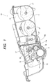
- Fig. 1 is a diagram of the principal section of a process cartridge according to the present invention
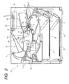
- Fig. 2 is a diagram of the principal section of an image forming apparatus according to the invention.
- the process cartridge is equipped with an image bearing body and process means working on the image bearing body.
- the process means includes, for example, charging means for charging the surface of the image bearing body, a developing apparatus for forming a toner image on the image bearing body, and cleaning means for removing the toner remaining on the surface of the image bearing body.
- the process cartridge 15 of the present embodiment disposes, as shown in Fig. 1, a charging roller 12 being the charging means; a developing roller 18, a developing blade 26 and a toner containing frame body 16 for containing toner as the developing means; and a cleaning blade 14 as the cleaning means around the electrophotographic photosensitive body drum (hereinafter referred to as a "photosensitive body drum") 11 being the image bearing body.
- a charging roller 12 being the charging means
- a cleaning blade 14 as the cleaning means around the electrophotographic photosensitive body drum (hereinafter referred to as a "photosensitive body drum") 11 being the image bearing body.
- Each component is integrally covered by a housing to be the process cartridge 15.
- the process cartridge 15 is configured to be detachably attachable to an image forming apparatus main body C.
- Fig. 2 shows the image forming apparatus in the state capable of forming an image after the process cartridge 15 has been mounted in the apparatus main body C.
- the process cartridge 15 can be detached from the apparatus main body C in conformity with the following procedures. That is: at first, a hoist arm 2 capable of supporting the left side end portion of the process cartridge 15 is raised with a not shown handle to swing the process cartridge 15 on a guide rail 24 of the apparatus main body C around a fulcrum foot 5 of the process cartridge 15; a guide portion 15a of the process cartridge 15 is thereby made to accord with a guide rail 24 of the apparatus main body C; and then the process cartridge 15 is pulled out toward the front side of Fig. 1 by a user, being gripped by the user's hand on a handle 25 (see Fig. 3).
- the attachment of the process cartridge 15 to the apparatus main body C is performed in conformity with the reverse procedures of the procedures at the detachment thereof described above.
- the process cartridge 15 is used for image formation in the state of being mounted in the apparatus main body C shown in Fig. 2.
- the image formation is performed in conformity with the following procedures. That is, at first, a sheet S as a recording medium is conveyed from sheet cassettes 6 mounted at the lower part of the apparatus with conveying rollers 7, and an exposing apparatus 8 selectively exposes the photosensitive body drum 11, which has uniformly been charged by the charging roller 12, to light synchronously with the sheet conveyance for forming a latent image. After that, toner contained in the toner containing frame body 16 is carried toward the developing roller 18, and a thin toner layer is borne on the surface of the developing roller 18 with the developing blade 26.
- a developing bias is applied to the developing roller 18 to feed toner on the surface of the photosensitive body drum 11 according to the latent image.
- the toner image on the photosensitive body drum 11 is then transferred to the conveyed sheet S by the application of a bias voltage to a transferring roller 9.
- the sheet S is conveyed to a fixing apparatus 10, and the toner image transferred on the sheet S is fixed by the fixing apparatus 10. Then, the sheet S is delivered to a discharging portion 3 at the upper part of the apparatus by discharging rollers 1.
- Fig. 1 and Figs. 3 to 7 are referred while the configuration of the process cartridge 15 is described.
- Fig. 7 is a perspective view showing the frame configuration of the process cartridge 15 before it is assembled.
- the process cartridge 15 is chiefly composed of three frame bodies: a cleaning frame body 13 in which the photosensitive body drum 11, the charging roller 12 and the cleaning blade 14 are integrally incorporated; a developing frame body 17 in which the developing roller 18 and the developing blade 26 (not shown in Fig. 7. See Fig. 1) are integrally supported; and the toner containing frame body 16 containing toner T therein.
- side covers 19 and 20 for supporting the three frame bodies 13, 17 and 16 integrally fix them on both the side faces of them to constitute the process cartridge 15.
- the cleaning frame body 13 fixes the cleaning blade 14 with machine screws or the like thereto, and supports the charging roller 12 rotatably at the core metal portions on both end portions of the charging roller 12 with bearing members (not shown) being put between the cleaning frame body 13 and the charging roller 12. Moreover, the cleaning frame body 13 rotatably supports the photosensitive body drum 11 at flange portions 11a and 11b on both end portions of the photosensitive body drum 11 with bearing members 22 and 23 being put between the cleaning frame body 13 and the photosensitive body drum 11. Incidentally, as shown in Fig. 4 and Fig.
- the flange portion 11a supports the so-called triangle coupling 11c to engage with a driving coupling of the apparatus main body C at an end portion of the flange portion 11a, and the flange portion 11a is driven from a driving apparatus in the apparatus main body C through the triangle coupling 11c to drive the photosensitive body drum 11.
- the toner containing frame body 16 contains toner T in its inside together with toner carrying members 27.
- the developing roller 18 including a magnet roller 18a, the developing blade 26 and a magnetic seal (not shown in Fig. 7) are disposed in the developing frame body 17.
- One side end of the magnet roller 18a is supported by a projecting portion 17e being a developing roller bearing of the developing frame body 17 and the other side end thereof is supported by the developing frame body 17, and the magnet roller 18a keeps a gap with the developing roller 18.
- the developing roller 18 is configured to perform the electric power supply thereto through an electric contact point disposed in the inside of the developing roller 18.
- an anti-climbing roller (not shown) for keeping the interval from the photosensitive body drum 11 constant is provided on the developing roller 18.
- the developing frame body 17 is supported by the cleaning frame body 13 swingably around a suspension hole 17d formed on one side face side of the developing roller 18 such that the center of the developing roller 18 goes toward the center of the photosensitive body drum 11.
- the process cartridge 15 is configured to pressurize the projecting portion 17e, which is fixed on a central axis line of the developing roller 18 in the lengthwise direction thereof on the other side face side of the developing frame body 17, toward the center of the photosensitive body drum 11.
- the projecting portion 17e is configured to be inserted into a groove 19e (an elongated hole in the shape of a straight line substantially parallel in the center direction of the photosensitive body drum 11 in the present embodiment) formed on the side cover 19 in the state movable to the center direction of the photosensitive body drum 11.
- an elastic member (not shown) is disposed in the inside of the groove 19e such that the elastic body pressurizes the projecting portion 17e to bias the developing roller 18 along the photosensitive body drum 11.
- the groove 19e also has the role of a locating hole for regulating the moving direction of the developing roller 18.
- gears which are respectively provided on the photosensitive body drum 11 and the developing roller 18 and mesh to each other, are designed to receive a force respectively in the direction of interlocking with each other around the suspension hole 17d lest the forces should work in the direction to separate the photosensitive body drum 11 and the developing roller 18 from each other.
- the elastic member provided in the groove 19e also pressurizes the developing roller 18 toward the photosensitive body drum 11 always.
- the side cover 19 on one side has a size covering a principal section of the process cartridge 15.
- the side cover 19 is disposed on one end of the process cartridge 15 in the lengthwise direction.
- the side cover 19 integrally supports the cleaning frame body 13 and the toner containing frame body 16 by fixing them thereto respectively.
- a hole portion 19a in the side cover 19 is located on the same axis as that of the center of the photosensitive body drum 11. At this time, if the location of the side cover 19 is performed by the use of the bearing member 22, the location can be determined highly precisely.
- a locating portion 19b formed at a position distant from the photosensitive body drum 11 as far as possible locates the position of side cover 19 in the rotational direction thereof together with a locating portion 13b formed on a side face of the cleaning frame body 13, and the side cover 19 and the cleaning frame body 13 are fixed to each other with several machine screws.
- the toner containing frame body 16 forms locating portions 16a and 16b on its one end face.
- the toner containing frame body 16 is located to the side cover 19 by means of the locating portions 16a and 16b and locating portions 19c and 19d disposed on the side cover 19.
- the toner containing frame body 16 is fixed to the side cover 19 with several machine screws.
- the side cover 20 on the other side is similarly configured.
- the bearing member 22 also has the role of a locating member of the process cartridge 15 to the apparatus main body C. Opening portions 16c and 17a are respectively formed in the toner containing frame bode 16 and the developing frame body 17 for the supply of toner from the toner containing frame body 16 to the developing roller 18. The opening portions 17a and 16c in the developing frame body 17 and the toner containing frame body 16 are connected through a seal member 21. Moreover, the toner containing frame body 16 is located by the side covers 19 and 20, the developing frame body 17 is located by the cleaning frame body 13. There is consequently the possibility that distortion is produced in either of the developing frame body 17 and the toner containing frame body 16 owing to dimension errors between them. Accordingly, the seal member 21 is made from a flexible material.
- Fig. 8 is a plan view of the developing apparatus seen from the direction orthogonal to the lengthwise direction of the developing roller 18.
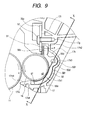
- Fig. 9 is a sectional view of the developing apparatus taken along IX-IX line in Fig. 8.
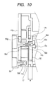
- Fig. 10 is a sectional view of the developing apparatus taken along X-X line in Fig. 9.
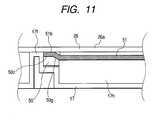
- Fig. 11 is a sectional view of the developing apparatus taken along XI-XI line in Fig. 8.
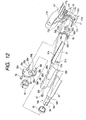
- Fig. 12 is a perspective view showing a state of each part of the developing apparatus before they are assembled.
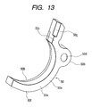
- Fig. 13 is a perspective view of a simplex magnetic seal.
- Fig. 14 is a perspective view showing only a developing bearing frame body and the developing frame body 17 before they are assembled.
- Fig. 15 is a perspective view of another embodiment of the developing bearing frame body.
- Fig. 16 is a perspective view showing only a developing roller and a magnetic seal.
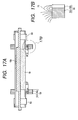
- Fig. 17A is a sectional view of the developing roller and the magnetic seal taken along XVII-XVII line in Fig. 16, and
- Fig. 17B is a macrograph of the part of 17B in Fig. 17A.
- the developing roller 18 and the developing blade 26 are incorporated into the developing frame body 17 as the components related to image formation.
- the developing blade 26 is composed of a sheet metal 26a having the thickness of about 1 mm to 2 mm and a polyurethane rubber 26b fixed on the sheet metal 26a by hot melt adhering or with a pressure sensitive adhesive double coated tape or the like.
- a silicon rubber may be employed as the developing blade 26.
- Female screws 17g are provided on anti-climbing planes 17f formed in the developing frame body 17 as blade fitting portions, and dowels (not shown) for location are formed at positions near to the centers of the anti-climbing planes 17f a little.
- fitting holes 26d formed in the sheet metal 26a are fitted to the dowels (not shown) each other.
- machine screws 57 are screwed into the female screws 17g through tapped holes 26c to fix the sheet metal 26a to the anti-climbing planes 17f.
- the position of the leading edge of the polyurethane rubber 26b is determined, and then the touching pressure of the polyurethane rubber 26b to the developing roller 18 is determined. Consequently, the distance from the leading edge of the polyurethane rubber 26b to the touching position is determined, and the development condition is determined.
- one end of the sheet metal 26a of the developing blade 26 is bent by the angle of about 90 degrees to form a bent portion 26e for the heightening of the rigidity of the sheet metal 26a in order that the polyurethane rubber 26b is touched to the developing roller 18 uniformly in the lengthwise direction of the developing roller 18.
- an elastic seal member 51 which is made from a moltopren (trade name) or the like and is formed in a shape of substantially a letter U, is stuck to the developing frame body 17 along its elastic seal seat surface 17h (see Fig. 12) at the upper part of the opening portion 17a in the lengthwise direction and its seat surfaces 17j in the widthwise direction for the prevention of the leakage of toner to the outside.
- a first straight line portion 51c of the elastic seal member 51 is stuck to the seat surface 17h of the developing frame body 17, and second straight line portions 51a of the seal member 51 are stuck to the seat surfaces 17j.
- the elastic seal member 51 is put between the developing frame body 17 and the developing blade 26 to be pinched out by them, and thereby the leakage of toner is prevented.
- Lug portions 51b are formed on the elastic seal member 51 at both end portions thereof to project from the end portions in the lengthwise direction of the seal member 51 by several millimeters.
- the lug portions 51b perform the role of locating the magnetic seal 50, which will be described later.
- the magnetic seals 50 are attached to grooves 17k formed on the surfaces adjoining (at the insides of arc surfaces 171 in the lengthwise direction of the developing roller 18) to the arc surfaces 171 and flat surfaces continuing upward from the arc surfaces 171 along the peripheral direction of the developing roller 18 at both end portions of the opening portion 17a in the lengthwise direction of the developing roller 18.
- the magnetic seals 50 will be described later in detail.
- a thin film elastic seal member (not shown), which abuts on a generating line of the developing roller 18, is stuck to a seat surface 17ml in the upper part of a lower jaw portion 17m of the developing frame body 17.
- the developing roller 18 is a cylindrical member made of a metal material of aluminum, stainless steel or the like.
- the outer diameter of the cylindrical shape of the developing roller 18 is about 16 mm to 20 mm, and the thickness of the cylindrical shape is about 0.5 mm to 1 mm.
- a surface treatment such as carbon coating, abrasive blasting or the like is performed to the surface of the developing roller 18 for the heightening of the electrification characteristic of developer. Only the carbon coating is performed in the present embodiment.
- Sleeve flanges (only one end portion of them is shown in Fig. 12) 18s, which are stepped cylindrical members made of a metal material of aluminum, stainless steel or the like, are force-fitted into both end portions of the developing roller 18.
- Each of the sleeve flanges 18s is coaxial with the developing roller 18, and is composed of a first cylindrical portion 18b and a second cylindrical portion 18c, the outer diameters of which are smaller in the order.
- the first cylindrical portion 18b is provided with a spacer roller 53 being a ring-shaped distance regulating member for regulating the opposed distance between the developing roller 18 and the photosensitive body drum 11.
- the space roller 53 is made from an insulating material such as polycetal or the like.
- a developing bearing frame body 55 (its especially enlarged perspective view seen from the reverse side is shown in Fig. 14) for supporting the developing roller 18 rotatably and locating it to the developing frame body 17 is disposed around the second cylindrical portion 18c. Moreover, two flat surfaces 18d are formed at the tip portion of the second cylindrical portion 18c, and a developing roller gear 54 made from a synthetic resin is fitted to the cylindrical portion 18c having the flat surfaces 18d.
- the developing roller gear 54 is driven by a helical drum gear (not shown) provided at an edge portion of the photosensitive body drum 11 to rotate the developing roller 18.
- the helical teeth of the drum gear are twisted such that the thrust thereof in the axial direction thereof works in the lengthwise direction of the developing roller 18.
- the developing bearing frame body 55 is made from a resin material producing a good slidable property, and is shaped to be a flat plate having a thickness of about 2 mm to 5 mm. At approximately the center of the flat plate portion, a cylindrical bearing portion 55a is formed. The inner diameter of the bearing portion 55a is 8 mm to 15 mm.
- the bearing portion 55a fits to the second cylindrical portion 18c of the sleeve flange 18s, and thereby the developing roller 18 slides therein while rotating.
- a dowel 55c including a first step portion 55d, and a second step portion 55e at its end portion, both being for locating the developing bearing frame body 55 against the developing frame body 17, is formed on the surface 55g of the flat plate portion of the developing bearing frame body 55 in substantially parallel to the bearing portion 55a.
- the dowel 55c performs the role of locating the developing bearing frame body 55 against the developing frame body 17.
- the first step portion 55d and the second step portion 55e, both being coaxial with the dowel 55c at the end portion of the dowel 55c, is used for the location of the magnetic seal 50, which will be described later.
- tapped holes 55b for the fixation of the developing bearing frame body 55 to the developing frame body 17 with machine screws 56 or the like, and a dowel 55f for the location of the developing bearing frame body 55 to the developing frame body 17 are formed on the same surface 55g.
- the dowel 55c of the developing bearing frame body 55 is fitted into a location hole 17c (shown in Fig. 14) formed in the developing frame body 17, and the dowel 55f is fitted into a fitting elongated hole 17o formed in e developing frame body 17, and further the surface 55g of the developing bearing frame body 55 is touched to a surface 17p of the developing frame body 17.
- the machine screws 56 are screwed into female screws 17q and 17r formed on the developing frame body 17 through the two tapped holes 55b, and the developing bearing frame body 55 is fixed to the developing frame body 17. Thereby, the positions of the developing blade 26 and the developing roller 18, both being fixed to the developing frame body 17, are surely determined, and stable images can be outputted.
- the material of the developing bearing frame body 55 is preferably a comparatively high priced material- having a good sliding property (for example, a bearing material based on poly phenylene sulfide (PPS) or polyamide (PA)). Accordingly, as shown in Fig. 15, if only a bearing portion is separated from a housing 100 as a bearing bushing 101, the quantity of the expensive material to be used is not needed so much, and the housing 100 can be made from a comparatively cheap material such as high-impact polystyrene (HIPS).
- HIPS high-impact polystyrene
- the magnetic seal 50 (shown in an especially enlarged figure in Fig. 13) is an injection-molded article having a width of 3 mm to 4 mm.
- a magnet 50a being a component of the magnetic seal 50 includes Nd-Fe-B magnetic power with a nylon binder.
- a magnetic plate 50b being another component of the magnetic seal 50 is made from iron and has a thickness of 1 mm to 1.5 mm.
- the magnet 50a and the magnetic plate 50b are molded by the insert molding such that the magnetic plate 50b is embedded in the magnet 50a except for the remaining inner periphery and the outside side face of the magnet 50.
- the joining by an adhesive, the joining by a pressure sensitive adhesive double coated tape, or the attraction joining only by a magnetic force can similarly bring about the advantages that will be described later.
- the gap between the developing roller 18 and the magnetic seal 50 is 0.1 mm to 0.7 mm, and the magnetic flux density on the surface of the developing roller 18 owing to the magnetic force of the magnetic seal 50 in this case is about 1,000 Gs to 2,000 Gs.
- the toner on the magnetic seal 50 does not diffuse to the outside of the opening portion 17a of the developing frame body 17 from the magnetic plate 50b, the toner can securely be held within a range where the magnetic force on the surface of the magnetic seal 50 is strong. Consequently, a good seal property such that toner does not leak out even if impact or the like is imposed on the process cartridge 15 when a user attaches or detaches the process cartridge 15 to the apparatus main body C can be obtained.
- the fact that the lines of magnetic forces 75 enter into the magnetic plate 50b by the disposition of the magnetic plate 50b on the side face of the magnet 50a is to converge the lines of magnetic forces 75, which has the tendency of divergence, into the magnetic plate 50b. Consequently, the magnetic flux density on the surface of the magnet 50a becomes large, which makes the magnetic force of the magnet 50 large. Hence, it is achieved to improve the sealing property furthermore. Besides, because a cheap magnet, which has a small magnetic force, can be used if the sealing property is not needed so strictly, the cost of the process cartridge 15 can be decreased.
- the magnetic seal 50 is located to the developing roller 18 by means of the developing frame body 17, the elastic seal member 51 and the developing bearing frame body 55, all being described above. That is, the magnetic seal 50 is located by the location to a location hole 50d of the magnetic seal 50 shown in Fig. 9 and by the biasing of the magnetic seal 50 in the rotation direction around the location hole 50d. The location is described on the basis of Fig. 8, Fig. 9, Fig. 10, Fig. 11 and Fig. 13 in detail.
- both the magnet 50a and the magnetic plate 50b have a half arc portion 50e (or the half arc portion of the magnetic seal 50), the inner periphery side of which forms a gap g1 with the developing roller 18, and an end face portion 50c, which offsets to the side of he developing frame body 17 halfway on the half arc portion 50e to extend upward in a straight line from the upper part of he half arc portion 50e.
- the cross section of the magnet 50a is nearly a square, and the cross section of the magnet 50a combined with the magnetic plate 50b is a square.
- An arc-shaped bending portion 50h projects towards the outside in the radial direction from the outer periphery 50f of the magnet 50a, and the location hole 50d is exists at the center of the arc of the bending portion 50h.
- the upper end of the magnetic plate 50b is fitted into the end face portion 50c, and the magnet 50a and the magnetic plate 50b form the same plane on the outside side face of the magnetic seal 50 in the lengthwise direction.
- a groove 17k (17k1, 17k2 and 17k3) for the attachment of the magnetic seal 50 is formed from the anti-climbing plane 17f, to which the developing blade 26 is attached, to an adjoining position to the arc surface 171 along an end portion of the developing roller 18.
- the groove 17k is composed of an arc groove 17k1 along the arc of the arc surface 171 (see Fig. 12), a straight line groove 17k2 along the anti-climbing plane 17f in a vertical direction, and a location groove 17k3, in which the bending portion 50h (the inner periphery of which forms the location hole 50d) of the magnetic seal 50 is just fitted.
- These grooves 17k1, 17k2 and 17k3 are continuously formed.
- the location groove 17k3 is recessed from the base of the arc groove 17k1.
- the width H (noted in Fig. 10) of the groove 17k and the width of the magnetic seal 50 are formed to be the same.
- the magnetic seal 50 is fitted into the groove 17k.
- the position of the magnetic seal 50 to the developing roller 18 in the lengthwise direction of the developing roller 18 is determined.
- the depth of each portion of the groove 17k for the attachment of the magnetic seal 50 thereto is deeper than the thickness of each corresponding portion of the magnetic seal 50 by 0.1 mm to 0.7 mm when the magnetic seal 50 is fitted into a predetermined position (the fitting will be described later).
- the surface of the outer periphery 50f of the magnetic seal 50 keeps a gap g2 (see Fig. 9) from the groove 17k of the developing frame body 17.
- a magnetic pole is disposed on the surface of the outer periphery 50f of the magnetic seal 50 as a magnetic pole is disposed on the surface opposed to the developing roller 18, and the leakage of toner to the outside can be prevented by the magnetic force caused by the magnetic pole.
- the magnetic seal 50 may be configured such that the magnetic plate 50b is extended to the surface of the outer periphery 50f to prevent the leakage of the magnetic force to the outside likewise on the developing roller 18 side for heightening the effect of the magnetic force.
- the location of the magnetic seal 50 is described in detail.
- the first step portion 55d at the end of the dowel (or a shaft) 55c projecting from the developing bearing frame body 55 described above is fitted into the location hole 50d of the magnetic seal 50, and thereby the magnetic seal 50 is rotatably supported around the first step portion 55d.
- the second step portion 55e at the end of the fist step portion 55d is fitted into a location hole 17s, which is coaxial with the location hole 17c of he developing frame body 17 and is formed on the side opposed to the groove 17k. Thereby, both the end faces of the magnetic seal 50 are supported.
- the magnetic seal 50 is supported at both the end faces, even if the shaft for location is slender in some degree, the magnetic seal 50 can be supported with a sufficient strength. Thereby, the space of the magnetic seal 50 can be reduced. Furthermore, although the dowel 55c being a location shaft easily falls in its formation process by molding, it is comparatively attained by molding to locate the center positions of the location holes 17c and 17s of the developing frame body 17 on the same axis precisely. Consequently, the location of the magnetic seal 50 can precisely be performed.
- the location of the magnetic seal 50 in its rotation direction is, as shown in Fig. 9, performed by the contact thereof to a lower end face 17k4 of the arc groove 17k1 of the developing frame body 17, i.e. an end face 17k4 falling down from the seat surface 17ml with an elastic seal (not shown) at the lower jaw portion 17m described above.
- a biasing force F for contacting the magnetic seal 50 to the end face 17k4 surely is caused by a repulsive force generated by the compression of mainly the lug portion 51b (see Fig. 12) of the elastic seal member 51 lying between the portion of the end face 50c in a straight line at the upper part of the magnetic seal 50 and the sheet metal 26a of the developing blade 26.
- the biasing force F works on the magnetic seal 50 in the clockwise direction around the location hole 50d, and thereby the magnetic seal 50 is surely located to the developing roller 18. Moreover, only the developing bearing frame body 55 exists between the magnetic seal 50 and the developing roller 18, and consequently the dispersion of the length of the gap g1, which generally becomes large by the accumulation of tolerances, is suppressed to be as small as possible. Consequently, the allowance for the leakage of toner can be improved. Moreover, although the gap g1 has conventionally been measured during a manufacturing process, the examination of the gap g1 becomes unnecessary because the accumulation of tolerances becomes small.
- the biasing force F is produced by means of a part of the elastic seal member 51, and thereby the location of the magnetic seal 50 can surely be performed at low cost without surplus parts.
- the elastic seal member 51 uses an insulating material, and thereby the elastic seal member 51 also performs the role of preventing leakage of a voltage when a high voltage is not desired to be applied to the sheet metal 26a of the developing blade 26, for example.
- the magnetic seals 50 are brought into the grooves 17k of the developing frame body 17 for the attachment of the magnetic seals 50 as indicated by an arrow D. Then, the half arc portions 50e of the magnetic seals 50 are fitted into the arc grooves 17k1, and the end face portions 50c are fitted into the straight line grooves 17k2. After that, the magnetic seals 50 are pushed into the arc grooves 17k1 and the straight line grooves 17k2 until the inner peripheral surfaces of the half arc portions 50e are at substantially the same heights as those of the arc surfaces 171.
- the first straight line portion 51c of the elastic seal member 51 is stuck to the elastic seat surface 17h being the end face of a rib of the developing frame body 17 in the lengthwise direction, and the second straight line portions 51a are stuck to the seat surfaces 17j of the developing frame body 17. And further, the lug portions 51b are stuck to the end face portions 50c of the magnetic seal 50.
- the elastic seal member 51 is not easy to stick (see Fig. 11).
- a tapered plane 50g (shown in Fig. 13) is formed.
- the lug portions 51b and the second straight line portions 51a may be formed to be separate bodies in view of material allotting.
- the fitting holes 26d formed in the sheet metal 26a are fitted to the dowels (not shown) each other.
- the machine screws 57 are screwed into the female screws 17g through the tapped holes 26c formed in the sheet metal 26a to fix the sheet metal 26a to the anti-climbing planes 17f.
- the unit of the developing roller 18 is temporarily put in the developing frame body 17 to be coaxial with the half arc portions 50e of the magnetic seals 50. At this time, the developing roller 18 does not directly contact with the magnetic seals 50 owing to the repulsive force of the polyurethane rubber 26b of the developing blade 26, and consequently the surface of the developing roller 18 is not injured by the magnetic seals 50.
- the developing bearing frame bodies 55 are assembled from both side face sides of the developing frame body 17 (though Fig. 12 shows one end side of the developing frame body 17, the other end side thereof is in the same configuration). That is, as described above by reference to Fig. 14, the dowels 55f are fitted into the fitting elongated holes 17o (which are elongated in the up and down direction in parallel to the surface of the sheet of Fig. 10), and further the surfaces 55g of the developing bearing frame bodies 55 are touched to the surfaces 17p of the developing frame body 17. Then, the machine screws 56 are screwed into the female screws 17q and 17r formed on the surfaces 17p through the tapped holes 55b formed in the developing bearing frame bodies 55, and the developing bearing frame bodies 55 are fixed to the developing frame body 17.
- the magnetic seals 50 are located around the first step portions 55d in the states of being able to tilt.
- the magnetic seals 50 receive moments around the first step portions 55d by forces biased by the repulsive force of the elastic seal member 51 lying between the magnetic seals 50 and the developing blade 26, and the lower end faces of the magnetic seals 50 are touched to the lower end faces 17k4 of the grooves 17k of the developing frame body 17.
- the positions of the magnetic seals 50 to the developing roller 18 are surely determined by a simple assembling method.
- the developing apparatus has a rotatable developer bearing member, a bearing member for holding the developer bearing member rotatably, and a seal member for preventing a leakage of a developer from an end portion of the developer bearing member in a lengthwise direction thereof to the lengthwise direction.
- the seal member is located by the bearing member.
Landscapes
- Physics & Mathematics (AREA)
- General Physics & Mathematics (AREA)
- Dry Development In Electrophotography (AREA)
- Magnetic Brush Developing In Electrophotography (AREA)
Abstract
Description
- The present invention relates to a developing apparatus to be mounted in an image forming apparatus, which uses a recording technique such as an electrophotographic process, an electrostatic recording process or the like, like a copying machine, a printer and the like. In particular, the present invention relates to a developing apparatus suitable for being mounted in a process cartridge capable of being detachably attachable to an image forming apparatus.
- An image forming apparatus using an electrophotography requires its maintenance such as the exchange of its photosensitive body drum, the replenishment or the exchange of its developer, the adjustment, the cleaning or the exchange of its other parts (its charger, its cleaner container or the like) when the image forming apparatus has been used for a long time. It is practically difficult for a person other than a serviceperson having an expert knowledge to do such maintenance work.
- Accordingly, an image forming apparatus employing an electrophotographic image forming process has employed a process cartridge system in which an electrophotographic photosensitive body and process means working on the electrophotographic photosensitive body are integrally formed to be a cartridge and the cartridge is made to be detachably attachable to the main body of the image forming apparatus. Because the process cartridge system enables a user to perform the maintenance of the apparatus by himself or herself without relying on a serviceperson, the process cartridge system has been abler to improve the operability of the image forming apparatus remarkably. Consequently, the process cartridge system is widely used in the image forming apparatus.
- Thereby, when the maintenance of an aforesaid process device becomes necessary, a user himself or herself can simply maintain or exchange a process cartridge, and consequently, it has become able to obtain a high grade image quality cheaply and easily.
- Developing means (or a developing apparatus) built in such a process cartridge is provided with seal members for preventing the outflow of toner to an area other than the developing area at both end portions of a developer bearing body such as a rotating developing roller mounted in the developing apparatus. An elastic body made of a felt, a expanded rubber or the like is widely used as a conventional seal member preventing the outflow of toner.
- A developing roller is provided with a magnet roller therein, and is rotatably supported by a developing container with sleeve bearings. Consequently, toner fed from the developing container attaches to the surface of the developing roller by a magnetic force of the magnet roller. After the thickness of the attached toner layer has been regulated by a developing blade, the toner attaches to a latent image on a photosensitive drum at a position opposed to the latent image on the photosensitive drum as the developing roller rotates. Consequently, the latent image is developed.
- The developing apparatus is further provided with elastic seal members attached at both end portions of the developing roller at the outsides of the developing area in the lengthwise direction thereof and at the inner part on the side opposite to the opening side of the developing roller attached to a developing frame body of the developing apparatus. The elastic seal member is pressed to the outer peripheral surface of the developing roller for preventing the outflow of toner.
- As for the aforesaid contact type seal members, because the elastic seals are pressed to the half of the outer peripheral surface of the developing roller, the conventional developing apparatus has the problem such that the load of the developing roller, which rotates at the time of a developing operation, is large, and the problem such that the elastic seal members deteriorate owing to the contact with the developing roller to make the sealing performance of the elastic seal members worse. Moreover, toner sometimes enters into the gaps between the developing roller and the elastic seal members though the amount of the entered toner is a little. The invasion of the toner sometimes caused the increase of torque or the increase of fluctuations of torque to produce the unevenness of the rotations of the developing roller. And then, a bad influence was sometimes exerted upon image formation.
- Accordingly, for solving those problems, a noncontact type seal member has been proposed. In the noncontact type seal member, seal members made of a magnetic body (hereinafter referred to as "magnetic seals") are disposed at both end portions of the developing roller with predetermined spaces between them for preventing the outflow of toner.
- The magnetic seal is made of a magnet. The magnetic seals are attached to both the end portions of the developing roller in the state of being wound around the end portions for being disposed with a predetermined gap (about 0.1 mm to 0.7 mm) to the outer peripheral surface of the developing roller. The magnetic seals are attached to the developing container in the wounded state along with the developing roller. The surfaces of the magnetic seals opposed to the developing roller are magnetized. Magnetic brushes formed by chained toner formed along each line of magnetic forces fill up the gaps between the outer peripheral surface of the developing roller and the surfaces of the magnetic seals to prevent the outflow of toner from the developing area.
- Moreover, because it is needed to locate the magnetic seals highly precisely to the developing roller, various locating methods have conventionally been devised.
- Incidentally, in both cases of the use of the aforesaid contact type seal member and the use of the noncontact type seal member, high accuracy of the attachment of them to the main body of the developing apparatus is required for securing their seal performances.
- The present invention was made in consideration of the aforesaid problems, and an object of the invention is to provide a developing apparatus in which toner does not easily leak out.
- Another object of the invention is to provide a developing apparatus in which seal members for preventing the leak out of toner from the end portions of its developing roller can be attached highly accurately.
- A further object of the invention is to provide a developing member to which seal members for preventing the leakage of toner from the end portions of its developing roller can be attached simply and accurately.
- A still further object of the invention is to provide a developing apparatus in which the positional accuracy of seal members to its developing roller is high.
- A still further object of the invention is to provide a developing apparatus including a rotatable developer bearing member, a bearing member for holding the developer bearing member rotatably, and a seal member for preventing the leakage of a developer from an end portion of the developer bearing member in the lengthwise direction thereof into the lengthwise direction, wherein the seal member is located by the bearing member.
- The still further object of the invention will be more apparent from the following detailed description taken in conjunction with the accompanying drawings.
-
- Fig. 1 is a schematic diagram of the principal section of a process cartridge according to an embodiment of the present invention;
- Fig. 2 is a schematic diagram of the principal section of the apparatus main body according to the embodiment of the invention;
- Fig. 3 is a side elevation showing the process cartridge of the embodiment of the invention seen from a side face thereof;
- Fig. 4 is a side elevation showing the process cartridge of the embodiment of the invention seen from another side face thereof;
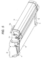
- Fig. 5 is a perspective view of the process cartridge in the embodiment of the invention;
- Fig. 6 is another perspective view of the process cartridge in the embodiment of the invention;
- Fig. 7 is a disassembled perspective view of a process cartridge frame body in the embodiment of the invention;
- Fig. 8 is a front view of a developing apparatus;
- Fig. 9 is a sectional view of the developing apparatus taken along IX-IX line in Fig. 8;
- Fig. 10 is a sectional view of the developing apparatus taken along X-X line in Fig. 9;
- Fig. 11 is a sectional view of the developing apparatus taken along XI-XI line in Fig. 8;
- Fig. 12 is a perspective view showing a state of each part of the developing apparatus before they are assembled;
- Fig. 13 is a perspective view of a simplex magnetic seal;
- Fig. 14 is a perspective view showing only a developing bearing frame body and a developing frame body before they are assembled;
- Fig. 15 is a perspective view of another embodiment of the developing bearing frame body;
- Fig. 16 is a perspective view showing only a developing roller and a magnetic seal; and
- Fig. 17A is a sectional view of the developing roller and the magnetic seal taken along an XVII-XVII line in Fig. 16, and Fig. 17B is a macrograph of the part of 17B in Fig. 17A.
-
- Fig. 1 to Fig. 17B are referred while an preferred embodiment of the present invention is described.
- Fig. 1 is a diagram of the principal section of a process cartridge according to the present invention, and Fig. 2 is a diagram of the principal section of an image forming apparatus according to the invention. The process cartridge is equipped with an image bearing body and process means working on the image bearing body. The process means includes, for example, charging means for charging the surface of the image bearing body, a developing apparatus for forming a toner image on the image bearing body, and cleaning means for removing the toner remaining on the surface of the image bearing body.
- The
process cartridge 15 of the present embodiment disposes, as shown in Fig. 1, a chargingroller 12 being the charging means; a developingroller 18, a developingblade 26 and a toner containingframe body 16 for containing toner as the developing means; and acleaning blade 14 as the cleaning means around the electrophotographic photosensitive body drum (hereinafter referred to as a "photosensitive body drum") 11 being the image bearing body. Each component is integrally covered by a housing to be theprocess cartridge 15. Theprocess cartridge 15 is configured to be detachably attachable to an image forming apparatus main body C. - Fig. 2 shows the image forming apparatus in the state capable of forming an image after the
process cartridge 15 has been mounted in the apparatus main body C. Theprocess cartridge 15 can be detached from the apparatus main body C in conformity with the following procedures. That is: at first, a hoistarm 2 capable of supporting the left side end portion of theprocess cartridge 15 is raised with a not shown handle to swing theprocess cartridge 15 on a guide rail 24 of the apparatus main body C around afulcrum foot 5 of theprocess cartridge 15; aguide portion 15a of theprocess cartridge 15 is thereby made to accord with a guide rail 24 of the apparatus main body C; and then theprocess cartridge 15 is pulled out toward the front side of Fig. 1 by a user, being gripped by the user's hand on a handle 25 (see Fig. 3). - The attachment of the
process cartridge 15 to the apparatus main body C is performed in conformity with the reverse procedures of the procedures at the detachment thereof described above. - The
process cartridge 15 is used for image formation in the state of being mounted in the apparatus main body C shown in Fig. 2. The image formation is performed in conformity with the following procedures. That is, at first, a sheet S as a recording medium is conveyed fromsheet cassettes 6 mounted at the lower part of the apparatus with conveyingrollers 7, and an exposingapparatus 8 selectively exposes thephotosensitive body drum 11, which has uniformly been charged by the chargingroller 12, to light synchronously with the sheet conveyance for forming a latent image. After that, toner contained in the toner containingframe body 16 is carried toward the developingroller 18, and a thin toner layer is borne on the surface of the developingroller 18 with the developingblade 26. And then, a developing bias is applied to the developingroller 18 to feed toner on the surface of thephotosensitive body drum 11 according to the latent image. The toner image on thephotosensitive body drum 11 is then transferred to the conveyed sheet S by the application of a bias voltage to a transferringroller 9. The sheet S is conveyed to a fixingapparatus 10, and the toner image transferred on the sheet S is fixed by the fixingapparatus 10. Then, the sheet S is delivered to a dischargingportion 3 at the upper part of the apparatus by discharging rollers 1. - Fig. 1 and Figs. 3 to 7 are referred while the configuration of the
process cartridge 15 is described. Fig. 7 is a perspective view showing the frame configuration of theprocess cartridge 15 before it is assembled. Theprocess cartridge 15 is chiefly composed of three frame bodies: a cleaningframe body 13 in which thephotosensitive body drum 11, the chargingroller 12 and thecleaning blade 14 are integrally incorporated; a developingframe body 17 in which the developingroller 18 and the developing blade 26 (not shown in Fig. 7. See Fig. 1) are integrally supported; and the toner containingframe body 16 containing toner T therein. Moreover, side covers 19 and 20 for supporting the threeframe bodies process cartridge 15. - The
cleaning frame body 13 fixes thecleaning blade 14 with machine screws or the like thereto, and supports the chargingroller 12 rotatably at the core metal portions on both end portions of the chargingroller 12 with bearing members (not shown) being put between the cleaningframe body 13 and the chargingroller 12. Moreover, thecleaning frame body 13 rotatably supports thephotosensitive body drum 11 atflange portions photosensitive body drum 11 with bearingmembers frame body 13 and thephotosensitive body drum 11. Incidentally, as shown in Fig. 4 and Fig. 5, theflange portion 11a supports the so-calledtriangle coupling 11c to engage with a driving coupling of the apparatus main body C at an end portion of theflange portion 11a, and theflange portion 11a is driven from a driving apparatus in the apparatus main body C through thetriangle coupling 11c to drive thephotosensitive body drum 11. The toner containingframe body 16 contains toner T in its inside together withtoner carrying members 27. - The developing
roller 18 including amagnet roller 18a, the developingblade 26 and a magnetic seal (not shown in Fig. 7) are disposed in the developingframe body 17. One side end of themagnet roller 18a is supported by a projectingportion 17e being a developing roller bearing of the developingframe body 17 and the other side end thereof is supported by the developingframe body 17, and themagnet roller 18a keeps a gap with the developingroller 18. The developingroller 18 is configured to perform the electric power supply thereto through an electric contact point disposed in the inside of the developingroller 18. Moreover, an anti-climbing roller (not shown) for keeping the interval from thephotosensitive body drum 11 constant is provided on the developingroller 18. - The developing
frame body 17 is supported by thecleaning frame body 13 swingably around asuspension hole 17d formed on one side face side of the developingroller 18 such that the center of the developingroller 18 goes toward the center of thephotosensitive body drum 11. - Moreover, the
process cartridge 15 is configured to pressurize the projectingportion 17e, which is fixed on a central axis line of the developingroller 18 in the lengthwise direction thereof on the other side face side of the developingframe body 17, toward the center of thephotosensitive body drum 11. The projectingportion 17e is configured to be inserted into agroove 19e (an elongated hole in the shape of a straight line substantially parallel in the center direction of thephotosensitive body drum 11 in the present embodiment) formed on theside cover 19 in the state movable to the center direction of thephotosensitive body drum 11. Moreover, an elastic member (not shown) is disposed in the inside of thegroove 19e such that the elastic body pressurizes the projectingportion 17e to bias the developingroller 18 along thephotosensitive body drum 11. - On the other hand, the
groove 19e also has the role of a locating hole for regulating the moving direction of the developingroller 18. - When a driving force works on the
process cartridge 15, not shown gears, which are respectively provided on thephotosensitive body drum 11 and the developingroller 18 and mesh to each other, are designed to receive a force respectively in the direction of interlocking with each other around thesuspension hole 17d lest the forces should work in the direction to separate thephotosensitive body drum 11 and the developingroller 18 from each other. Moreover, the elastic member provided in thegroove 19e also pressurizes the developingroller 18 toward thephotosensitive body drum 11 always. - The side cover 19 on one side has a size covering a principal section of the
process cartridge 15. The side cover 19 is disposed on one end of theprocess cartridge 15 in the lengthwise direction. The side cover 19 integrally supports thecleaning frame body 13 and the toner containingframe body 16 by fixing them thereto respectively. Ahole portion 19a in theside cover 19 is located on the same axis as that of the center of thephotosensitive body drum 11. At this time, if the location of theside cover 19 is performed by the use of the bearingmember 22, the location can be determined highly precisely. Moreover, a locatingportion 19b formed at a position distant from thephotosensitive body drum 11 as far as possible locates the position of side cover 19 in the rotational direction thereof together with a locatingportion 13b formed on a side face of thecleaning frame body 13, and theside cover 19 and thecleaning frame body 13 are fixed to each other with several machine screws. Furthermore, the toner containingframe body 16forms locating portions frame body 16 is located to theside cover 19 by means of the locatingportions portions side cover 19. The toner containingframe body 16 is fixed to theside cover 19 with several machine screws. The side cover 20 on the other side is similarly configured. - Moreover, the bearing
member 22 also has the role of a locating member of theprocess cartridge 15 to the apparatus main bodyC. Opening portions frame body 17 for the supply of toner from the toner containingframe body 16 to the developingroller 18. The openingportions frame body 17 and the toner containingframe body 16 are connected through aseal member 21. Moreover, the toner containingframe body 16 is located by the side covers 19 and 20, the developingframe body 17 is located by thecleaning frame body 13. There is consequently the possibility that distortion is produced in either of the developingframe body 17 and the toner containingframe body 16 owing to dimension errors between them. Accordingly, theseal member 21 is made from a flexible material. In such a configuration, if toner increases in theprocess cartridge 15, the load owing to the increased toner is imposed on the side covers 19 and 20, and no loads are imposed on the developingroller 18. Consequently, no surplus loads are imposed on thephotosensitive body drum 11, and stable images can be obtained. Moreover, because the threeframe bodies respective frame bodies frame bodies - Next, the developing apparatus is described more minutely. Fig. 8 is a plan view of the developing apparatus seen from the direction orthogonal to the lengthwise direction of the developing
roller 18. Fig. 9 is a sectional view of the developing apparatus taken along IX-IX line in Fig. 8. Fig. 10 is a sectional view of the developing apparatus taken along X-X line in Fig. 9. Fig. 11 is a sectional view of the developing apparatus taken along XI-XI line in Fig. 8. Fig. 12 is a perspective view showing a state of each part of the developing apparatus before they are assembled. Fig. 13 is a perspective view of a simplex magnetic seal. Fig. 14 is a perspective view showing only a developing bearing frame body and the developingframe body 17 before they are assembled. Fig. 15 is a perspective view of another embodiment of the developing bearing frame body. Fig. 16 is a perspective view showing only a developing roller and a magnetic seal. Fig. 17A is a sectional view of the developing roller and the magnetic seal taken along XVII-XVII line in Fig. 16, and Fig. 17B is a macrograph of the part of 17B in Fig. 17A. - As described above, the developing
roller 18 and the developingblade 26 are incorporated into the developingframe body 17 as the components related to image formation. - As shown in Fig. 12, the developing
blade 26 is composed of asheet metal 26a having the thickness of about 1 mm to 2 mm and apolyurethane rubber 26b fixed on thesheet metal 26a by hot melt adhering or with a pressure sensitive adhesive double coated tape or the like. By the contact of thepolyurethane rubber 26b with a generating line of the developingroller 18, the quantity of the toner on the peripheral surface of the developingroller 18 is regulated. Incidentally, a silicon rubber may be employed as the developingblade 26.Female screws 17g are provided onanti-climbing planes 17f formed in the developingframe body 17 as blade fitting portions, and dowels (not shown) for location are formed at positions near to the centers of theanti-climbing planes 17f a little. Accordingly,fitting holes 26d formed in thesheet metal 26a are fitted to the dowels (not shown) each other. After that,machine screws 57 are screwed into thefemale screws 17g through tappedholes 26c to fix thesheet metal 26a to theanti-climbing planes 17f. Thus, the position of the leading edge of thepolyurethane rubber 26b is determined, and then the touching pressure of thepolyurethane rubber 26b to the developingroller 18 is determined. Consequently, the distance from the leading edge of thepolyurethane rubber 26b to the touching position is determined, and the development condition is determined. Moreover, one end of thesheet metal 26a of the developingblade 26 is bent by the angle of about 90 degrees to form abent portion 26e for the heightening of the rigidity of thesheet metal 26a in order that thepolyurethane rubber 26b is touched to the developingroller 18 uniformly in the lengthwise direction of the developingroller 18. - Incidentally, an
elastic seal member 51, which is made from a moltopren (trade name) or the like and is formed in a shape of substantially a letter U, is stuck to the developingframe body 17 along its elasticseal seat surface 17h (see Fig. 12) at the upper part of theopening portion 17a in the lengthwise direction and itsseat surfaces 17j in the widthwise direction for the prevention of the leakage of toner to the outside. A firststraight line portion 51c of theelastic seal member 51 is stuck to theseat surface 17h of the developingframe body 17, and secondstraight line portions 51a of theseal member 51 are stuck to theseat surfaces 17j. Theelastic seal member 51 is put between the developingframe body 17 and the developingblade 26 to be pinched out by them, and thereby the leakage of toner is prevented.Lug portions 51b are formed on theelastic seal member 51 at both end portions thereof to project from the end portions in the lengthwise direction of theseal member 51 by several millimeters. Thelug portions 51b perform the role of locating themagnetic seal 50, which will be described later. - Moreover, as shown in Fig. 9 and Fig. 12, the
magnetic seals 50 are attached togrooves 17k formed on the surfaces adjoining (at the insides of arc surfaces 171 in the lengthwise direction of the developing roller 18) to the arc surfaces 171 and flat surfaces continuing upward from the arc surfaces 171 along the peripheral direction of the developingroller 18 at both end portions of theopening portion 17a in the lengthwise direction of the developingroller 18. Themagnetic seals 50 will be described later in detail. - Furthermore, a thin film elastic seal member (not shown), which abuts on a generating line of the developing
roller 18, is stuck to a seat surface 17ml in the upper part of alower jaw portion 17m of the developingframe body 17. - The developing
roller 18 is a cylindrical member made of a metal material of aluminum, stainless steel or the like. The outer diameter of the cylindrical shape of the developingroller 18 is about 16 mm to 20 mm, and the thickness of the cylindrical shape is about 0.5 mm to 1 mm. A surface treatment such as carbon coating, abrasive blasting or the like is performed to the surface of the developingroller 18 for the heightening of the electrification characteristic of developer. Only the carbon coating is performed in the present embodiment. - Sleeve flanges (only one end portion of them is shown in Fig. 12) 18s, which are stepped cylindrical members made of a metal material of aluminum, stainless steel or the like, are force-fitted into both end portions of the developing
roller 18. Each of thesleeve flanges 18s is coaxial with the developingroller 18, and is composed of a firstcylindrical portion 18b and a secondcylindrical portion 18c, the outer diameters of which are smaller in the order. The firstcylindrical portion 18b is provided with aspacer roller 53 being a ring-shaped distance regulating member for regulating the opposed distance between the developingroller 18 and thephotosensitive body drum 11. Thespace roller 53 is made from an insulating material such as polycetal or the like. A developing bearing frame body 55 (its especially enlarged perspective view seen from the reverse side is shown in Fig. 14) for supporting the developingroller 18 rotatably and locating it to the developingframe body 17 is disposed around the secondcylindrical portion 18c. Moreover, twoflat surfaces 18d are formed at the tip portion of the secondcylindrical portion 18c, and a developingroller gear 54 made from a synthetic resin is fitted to thecylindrical portion 18c having theflat surfaces 18d. The developingroller gear 54 is driven by a helical drum gear (not shown) provided at an edge portion of thephotosensitive body drum 11 to rotate the developingroller 18. The helical teeth of the drum gear are twisted such that the thrust thereof in the axial direction thereof works in the lengthwise direction of the developingroller 18. Moreover, a magnet roller (designated by areference numeral 18a in Fig. 17A) for make toner adhere to the peripheral surface of the developingroller 18 is built in the developingroller 18. Because the sleeve flange on the other end portion of the developingroller 18 has a similar configuration, the descriptions thereof is here omitted. The developingbearing frame body 55 is made from a resin material producing a good slidable property, and is shaped to be a flat plate having a thickness of about 2 mm to 5 mm. At approximately the center of the flat plate portion, acylindrical bearing portion 55a is formed. The inner diameter of the bearingportion 55a is 8 mm to 15 mm. The bearingportion 55a fits to the secondcylindrical portion 18c of thesleeve flange 18s, and thereby the developingroller 18 slides therein while rotating. Moreover, adowel 55c including afirst step portion 55d, and asecond step portion 55e at its end portion, both being for locating the developingbearing frame body 55 against the developingframe body 17, is formed on thesurface 55g of the flat plate portion of the developingbearing frame body 55 in substantially parallel to the bearingportion 55a. Thedowel 55c performs the role of locating the developingbearing frame body 55 against the developingframe body 17. Thefirst step portion 55d and thesecond step portion 55e, both being coaxial with thedowel 55c at the end portion of thedowel 55c, is used for the location of themagnetic seal 50, which will be described later. Moreover, on thesame surface 55g, tappedholes 55b for the fixation of the developingbearing frame body 55 to the developingframe body 17 withmachine screws 56 or the like, and adowel 55f for the location of the developingbearing frame body 55 to the developingframe body 17 are formed. Thedowel 55c of the developingbearing frame body 55 is fitted into alocation hole 17c (shown in Fig. 14) formed in the developingframe body 17, and thedowel 55f is fitted into a fitting elongated hole 17o formed in e developingframe body 17, and further thesurface 55g of the developingbearing frame body 55 is touched to asurface 17p of the developingframe body 17. Then, themachine screws 56 are screwed intofemale screws 17q and 17r formed on the developingframe body 17 through the two tappedholes 55b, and the developingbearing frame body 55 is fixed to the developingframe body 17. Thereby, the positions of the developingblade 26 and the developingroller 18, both being fixed to the developingframe body 17, are surely determined, and stable images can be outputted. - Because the developing
roller 18 slides in the bearingportion 55a of the developingbearing frame body 55 mentioned above, the material of the developingbearing frame body 55 is preferably a comparatively high priced material- having a good sliding property (for example, a bearing material based on poly phenylene sulfide (PPS) or polyamide (PA)). Accordingly, as shown in Fig. 15, if only a bearing portion is separated from ahousing 100 as a bearingbushing 101, the quantity of the expensive material to be used is not needed so much, and thehousing 100 can be made from a comparatively cheap material such as high-impact polystyrene (HIPS). - The magnetic seal 50 (shown in an especially enlarged figure in Fig. 13) is an injection-molded article having a width of 3 mm to 4 mm. A
magnet 50a being a component of themagnetic seal 50 includes Nd-Fe-B magnetic power with a nylon binder. Amagnetic plate 50b being another component of themagnetic seal 50 is made from iron and has a thickness of 1 mm to 1.5 mm. Themagnet 50a and themagnetic plate 50b are molded by the insert molding such that themagnetic plate 50b is embedded in themagnet 50a except for the remaining inner periphery and the outside side face of themagnet 50. However, the joining by an adhesive, the joining by a pressure sensitive adhesive double coated tape, or the attraction joining only by a magnetic force can similarly bring about the advantages that will be described later. Moreover, the gap between the developingroller 18 and themagnetic seal 50 is 0.1 mm to 0.7 mm, and the magnetic flux density on the surface of the developingroller 18 owing to the magnetic force of themagnetic seal 50 in this case is about 1,000 Gs to 2,000 Gs. Then, as shown in Fig. 16, in the state such that twomagnetic seals 50 are fixed to the developingframe body 17, themagnets 50a of the twomagnetic seals 50 are located to be opposed to each other. - By the disposition of the two
magnetic seals 50 in the way described above, the lines ofmagnetic forces 75 of each of themagnetic seals 50 are formed between themagnet 50a and themagnetic plate 50b to enter into themagnetic plate 50b having a higher permeability as shown in Fig. 17B, which is a macrograph of the part of 17B in Fig. 17A. Consequently, no lines of magnetic forces expand to the outside of the width of themagnetic seal 50. - Consequently, no toner diffusing along the lines of
magnetic forces 75 on the surface of themagnetic seal 50 exists on the outside of themagnetic plate 50b on the side of themagnetic plate 50b (or the outside of theopening portion 17a). The phenomenon such that toner is touched to thespacer roller 53 being a distance regulating member owing to the rotations of the developingroller 18 does not happen. Consequently, thespacer roller 53 can be approached to the side face of themagnetic seal 50, and thereby naturally theprocess cartridge 15 can be miniaturized, and the apparatus main body C can also be miniaturized. - Moreover, because the toner on the
magnetic seal 50 does not diffuse to the outside of theopening portion 17a of the developingframe body 17 from themagnetic plate 50b, the toner can securely be held within a range where the magnetic force on the surface of themagnetic seal 50 is strong. Consequently, a good seal property such that toner does not leak out even if impact or the like is imposed on theprocess cartridge 15 when a user attaches or detaches theprocess cartridge 15 to the apparatus main body C can be obtained. - Moreover, the fact that the lines of
magnetic forces 75 enter into themagnetic plate 50b by the disposition of themagnetic plate 50b on the side face of themagnet 50a is to converge the lines ofmagnetic forces 75, which has the tendency of divergence, into themagnetic plate 50b. Consequently, the magnetic flux density on the surface of themagnet 50a becomes large, which makes the magnetic force of themagnet 50 large. Hence, it is achieved to improve the sealing property furthermore. Besides, because a cheap magnet, which has a small magnetic force, can be used if the sealing property is not needed so strictly, the cost of theprocess cartridge 15 can be decreased. - The
magnetic seal 50 is located to the developingroller 18 by means of the developingframe body 17, theelastic seal member 51 and the developingbearing frame body 55, all being described above. That is, themagnetic seal 50 is located by the location to alocation hole 50d of themagnetic seal 50 shown in Fig. 9 and by the biasing of themagnetic seal 50 in the rotation direction around thelocation hole 50d. The location is described on the basis of Fig. 8, Fig. 9, Fig. 10, Fig. 11 and Fig. 13 in detail. - As shown in Fig. 9, both the
magnet 50a and themagnetic plate 50b have ahalf arc portion 50e (or the half arc portion of the magnetic seal 50), the inner periphery side of which forms a gap g1 with the developingroller 18, and anend face portion 50c, which offsets to the side of he developingframe body 17 halfway on thehalf arc portion 50e to extend upward in a straight line from the upper part of hehalf arc portion 50e. The cross section of themagnet 50a is nearly a square, and the cross section of themagnet 50a combined with themagnetic plate 50b is a square. An arc-shapedbending portion 50h projects towards the outside in the radial direction from theouter periphery 50f of themagnet 50a, and thelocation hole 50d is exists at the center of the arc of the bendingportion 50h. As shown in Fig. 13, the upper end of themagnetic plate 50b is fitted into theend face portion 50c, and themagnet 50a and themagnetic plate 50b form the same plane on the outside side face of themagnetic seal 50 in the lengthwise direction. - As shown in Fig. 9 and Fig. 12, a
groove 17k (17k1, 17k2 and 17k3) for the attachment of themagnetic seal 50 is formed from theanti-climbing plane 17f, to which the developingblade 26 is attached, to an adjoining position to thearc surface 171 along an end portion of the developingroller 18. Thegroove 17k is composed of an arc groove 17k1 along the arc of the arc surface 171 (see Fig. 12), a straight line groove 17k2 along theanti-climbing plane 17f in a vertical direction, and a location groove 17k3, in which the bendingportion 50h (the inner periphery of which forms thelocation hole 50d) of themagnetic seal 50 is just fitted. These grooves 17k1, 17k2 and 17k3 are continuously formed. The location groove 17k3 is recessed from the base of the arc groove 17k1. The width H (noted in Fig. 10) of thegroove 17k and the width of themagnetic seal 50 are formed to be the same. And, themagnetic seal 50 is fitted into thegroove 17k. Thereby, the position of themagnetic seal 50 to the developingroller 18 in the lengthwise direction of the developingroller 18 is determined. Moreover, the depth of each portion of thegroove 17k for the attachment of themagnetic seal 50 thereto is deeper than the thickness of each corresponding portion of themagnetic seal 50 by 0.1 mm to 0.7 mm when themagnetic seal 50 is fitted into a predetermined position (the fitting will be described later). That is, the surface of theouter periphery 50f of themagnetic seal 50 keeps a gap g2 (see Fig. 9) from thegroove 17k of the developingframe body 17. For the prevention of the leakage of toner through the gap g2, a magnetic pole is disposed on the surface of theouter periphery 50f of themagnetic seal 50 as a magnetic pole is disposed on the surface opposed to the developingroller 18, and the leakage of toner to the outside can be prevented by the magnetic force caused by the magnetic pole. Moreover, themagnetic seal 50 may be configured such that themagnetic plate 50b is extended to the surface of theouter periphery 50f to prevent the leakage of the magnetic force to the outside likewise on the developingroller 18 side for heightening the effect of the magnetic force. - Next, the location of the
magnetic seal 50 is described in detail. As shown in Fig. 10, thefirst step portion 55d at the end of the dowel (or a shaft) 55c projecting from the developingbearing frame body 55 described above is fitted into thelocation hole 50d of themagnetic seal 50, and thereby themagnetic seal 50 is rotatably supported around thefirst step portion 55d. Moreover, thesecond step portion 55e at the end of thefist step portion 55d is fitted into alocation hole 17s, which is coaxial with thelocation hole 17c of he developingframe body 17 and is formed on the side opposed to thegroove 17k. Thereby, both the end faces of themagnetic seal 50 are supported. Because themagnetic seal 50 is supported at both the end faces, even if the shaft for location is slender in some degree, themagnetic seal 50 can be supported with a sufficient strength. Thereby, the space of themagnetic seal 50 can be reduced. Furthermore, although thedowel 55c being a location shaft easily falls in its formation process by molding, it is comparatively attained by molding to locate the center positions of the location holes 17c and 17s of the developingframe body 17 on the same axis precisely. Consequently, the location of themagnetic seal 50 can precisely be performed. - Next, the location of the
magnetic seal 50 in its rotation direction is, as shown in Fig. 9, performed by the contact thereof to a lower end face 17k4 of the arc groove 17k1 of the developingframe body 17, i.e. an end face 17k4 falling down from the seat surface 17ml with an elastic seal (not shown) at thelower jaw portion 17m described above. Moreover, a biasing force F for contacting themagnetic seal 50 to the end face 17k4 surely is caused by a repulsive force generated by the compression of mainly thelug portion 51b (see Fig. 12) of theelastic seal member 51 lying between the portion of theend face 50c in a straight line at the upper part of themagnetic seal 50 and thesheet metal 26a of the developingblade 26. Thus the biasing force F works on themagnetic seal 50 in the clockwise direction around thelocation hole 50d, and thereby themagnetic seal 50 is surely located to the developingroller 18. Moreover, only the developingbearing frame body 55 exists between themagnetic seal 50 and the developingroller 18, and consequently the dispersion of the length of the gap g1, which generally becomes large by the accumulation of tolerances, is suppressed to be as small as possible. Consequently, the allowance for the leakage of toner can be improved. Moreover, although the gap g1 has conventionally been measured during a manufacturing process, the examination of the gap g1 becomes unnecessary because the accumulation of tolerances becomes small. Moreover, the biasing force F is produced by means of a part of theelastic seal member 51, and thereby the location of themagnetic seal 50 can surely be performed at low cost without surplus parts. Furthermore, theelastic seal member 51 uses an insulating material, and thereby theelastic seal member 51 also performs the role of preventing leakage of a voltage when a high voltage is not desired to be applied to thesheet metal 26a of the developingblade 26, for example. - Next, the assembly of the
magnetic seals 50 until their positions are determined is described on the basis of Fig. 12. - As shown in Fig. 12, the
magnetic seals 50 are brought into thegrooves 17k of the developingframe body 17 for the attachment of themagnetic seals 50 as indicated by an arrow D. Then, thehalf arc portions 50e of themagnetic seals 50 are fitted into the arc grooves 17k1, and theend face portions 50c are fitted into the straight line grooves 17k2. After that, themagnetic seals 50 are pushed into the arc grooves 17k1 and the straight line grooves 17k2 until the inner peripheral surfaces of thehalf arc portions 50e are at substantially the same heights as those of the arc surfaces 171. Next, the firststraight line portion 51c of theelastic seal member 51 is stuck to theelastic seat surface 17h being the end face of a rib of the developingframe body 17 in the lengthwise direction, and the secondstraight line portions 51a are stuck to the seat surfaces 17j of the developingframe body 17. And further, thelug portions 51b are stuck to theend face portions 50c of themagnetic seal 50. At this time, because the heights of the elasticseal seat surface 17h and themagnetic seal 50 are different from each other, theelastic seal member 51 is not easy to stick (see Fig. 11). For making it easy to stick theelastic seal member 51, a taperedplane 50g (shown in Fig. 13) is formed. Moreover, thelug portions 51b and the secondstraight line portions 51a may be formed to be separate bodies in view of material allotting. As for the incorporation of the developingblade 26, as described above, thefitting holes 26d formed in thesheet metal 26a are fitted to the dowels (not shown) each other. After that, themachine screws 57 are screwed into thefemale screws 17g through the tappedholes 26c formed in thesheet metal 26a to fix thesheet metal 26a to theanti-climbing planes 17f. Next, the unit of the developingroller 18 is temporarily put in the developingframe body 17 to be coaxial with thehalf arc portions 50e of the magnetic seals 50. At this time, the developingroller 18 does not directly contact with themagnetic seals 50 owing to the repulsive force of thepolyurethane rubber 26b of the developingblade 26, and consequently the surface of the developingroller 18 is not injured by the magnetic seals 50. - Lastly, the developing
bearing frame bodies 55 are assembled from both side face sides of the developing frame body 17 (though Fig. 12 shows one end side of the developingframe body 17, the other end side thereof is in the same configuration). That is, as described above by reference to Fig. 14, thedowels 55f are fitted into the fitting elongated holes 17o (which are elongated in the up and down direction in parallel to the surface of the sheet of Fig. 10), and further thesurfaces 55g of the developingbearing frame bodies 55 are touched to thesurfaces 17p of the developingframe body 17. Then, themachine screws 56 are screwed into thefemale screws 17q and 17r formed on thesurfaces 17p through the tappedholes 55b formed in the developingbearing frame bodies 55, and the developingbearing frame bodies 55 are fixed to the developingframe body 17. Thereby, themagnetic seals 50 are located around thefirst step portions 55d in the states of being able to tilt. Themagnetic seals 50 receive moments around thefirst step portions 55d by forces biased by the repulsive force of theelastic seal member 51 lying between themagnetic seals 50 and the developingblade 26, and the lower end faces of themagnetic seals 50 are touched to the lower end faces 17k4 of thegrooves 17k of the developingframe body 17. - As described above, the positions of the
magnetic seals 50 to the developingroller 18 are surely determined by a simple assembling method. - The present invention is not bounded to the aforesaid embodiments, and many modifications within the scope of the technical concepts of the present invention can be included therein.
- The developing apparatus has a rotatable developer bearing member, a bearing member for holding the developer bearing member rotatably, and a seal member for preventing a leakage of a developer from an end portion of the developer bearing member in a lengthwise direction thereof to the lengthwise direction. In the developing apparatus, the seal member is located by the bearing member.
Claims (13)
- A developing apparatus comprising:wherein said seal member is located by said bearing member.a rotatable developer bearing member;a bearing member for holding said developer bearing member rotatably; anda seal member for preventing a leakage of a developer from an end portion of said developer bearing member in a lengthwise direction thereof to the lengthwise direction,
- A developing apparatus according to claim 1, wherein said seal member is disposed along a peripheral surface of the end portion of said developer bearing member in the lengthwise direction thereof.
- A developing apparatus according to claim 1, wherein said bearing member includes a shaft for locating said seal member rotatably, and said seal member includes a hole to which said shaft is fitted.
- A developing apparatus according to claim 3, further comprising locating means for determining a position of said seal member in a rotation direction thereof around said shaft.
- A developing apparatus according to claim 4, wherein said locating means includes biasing means for biasing said seal member in the rotation direction, and a receiving portion for receiving said seal member biased by said biasing means.
- A developing apparatus according to claim 5, further comprising a regulating member for regulating a quantity of the developer to be borne by said developer bearing member, and an elastic member provided between said regulating member and said seal member, wherein said regulating member and said elastic member work as said biasing means.
- A developing apparatus according to claim 6, wherein said elastic member has an insulating property.
- A developing apparatus according to claim 6, wherein said elastic member is a foam urethane.
- A developing apparatus according to claim 1, wherein said seal member is a part to be attached to a main body of said developing apparatus from a direction crossing with the longwise direction, and said bearing member is a part to be attached to said main body from a direction parallel to the lengthwise direction.
- A developing apparatus according to claim 3, wherein, when said bearing member is attached to a main body of said developing apparatus, said shaft passes through a first hole formed in said main body, and next passes through said hole of said seal member, and further enters into a second hole formed on said main body.
- A developing apparatus according to claim 10, wherein said shaft is a stepped shaft an end portion of which is slender.
- A developing apparatus according to claim 1, wherein said seal member magnetically prevents the developer from leaking.
- A developing apparatus according to claim 1, wherein said developing apparatus is provided in a process cartridge that includes at least a photosensitive body and is detachably attachable to an image forming apparatus.
Applications Claiming Priority (2)
| Application Number | Priority Date | Filing Date | Title |
|---|---|---|---|
| JP2001056572A JP4672885B2 (en) | 2001-03-01 | 2001-03-01 | Developing device and process cartridge |
| JP2001056572 | 2001-03-01 |
Publications (2)
| Publication Number | Publication Date |
|---|---|
| EP1239342A1 true EP1239342A1 (en) | 2002-09-11 |
| EP1239342B1 EP1239342B1 (en) | 2008-10-29 |
Family
ID=18916580
Family Applications (1)
| Application Number | Title | Priority Date | Filing Date |
|---|---|---|---|
| EP02004643A Expired - Lifetime EP1239342B1 (en) | 2001-03-01 | 2002-02-28 | Developing apparatus provided with magnetic seal functions on both sides of a developing roller |
Country Status (4)
| Country | Link |
|---|---|
| US (1) | US6671473B2 (en) |
| EP (1) | EP1239342B1 (en) |
| JP (1) | JP4672885B2 (en) |
| DE (1) | DE60229579D1 (en) |
Families Citing this family (15)
| Publication number | Priority date | Publication date | Assignee | Title |
|---|---|---|---|---|
| JP4217474B2 (en) | 2002-12-20 | 2009-02-04 | キヤノン株式会社 | Magnetic seal member, developing device using the same, process cartridge, and electrophotographic image forming apparatus |
| JP4617126B2 (en) * | 2004-09-13 | 2011-01-19 | キヤノン株式会社 | Developing device and process cartridge |
| JP4659468B2 (en) * | 2005-01-26 | 2011-03-30 | キヤノン株式会社 | Development unit and process cartridge |
| US7356292B2 (en) * | 2006-06-15 | 2008-04-08 | Xerox Corporation | Electrostatographic developer unit having multiple magnetic brush rolls with a magnetic restrictor for carrier particle emission control |
| JP4948382B2 (en) | 2006-12-22 | 2012-06-06 | キヤノン株式会社 | Coupling member for mounting photosensitive drum |
| JP4498407B2 (en) | 2006-12-22 | 2010-07-07 | キヤノン株式会社 | Process cartridge, electrophotographic image forming apparatus, and electrophotographic photosensitive drum unit |
| US7627265B2 (en) * | 2007-01-15 | 2009-12-01 | Lexmark International, Inc. | Seal and seal assembly for an image forming apparatus |
| JP5311854B2 (en) | 2007-03-23 | 2013-10-09 | キヤノン株式会社 | Electrophotographic image forming apparatus, developing device, and coupling member |
| US8099012B2 (en) * | 2007-12-18 | 2012-01-17 | Lexmark International, Inc. | Developer roll lip seal |
| US8116657B2 (en) * | 2007-12-18 | 2012-02-14 | Lexmark International, Inc. | Upper seal for inhibiting doctor blade toner leakage |
| JP5328230B2 (en) | 2008-06-10 | 2013-10-30 | キヤノン株式会社 | Cartridge and electrophotographic image forming apparatus using the cartridge |
| FR2951549B1 (en) | 2009-10-15 | 2013-08-23 | Olivier Schussler | PROCESS FOR OBTAINING IMPLANTABLE MEDICAL BIOPROTHESES |
| JP2012078548A (en) * | 2010-10-01 | 2012-04-19 | Fuji Xerox Co Ltd | Developing device and image forming apparatus |
| JP6226661B2 (en) * | 2013-09-18 | 2017-11-08 | キヤノン株式会社 | Process cartridge |
| JP7599870B2 (en) | 2020-08-31 | 2024-12-16 | キヤノン株式会社 | Developing device and manufacturing method thereof |
Citations (3)
| Publication number | Priority date | Publication date | Assignee | Title |
|---|---|---|---|---|
| JPS5730859A (en) | 1980-07-31 | 1982-02-19 | Fuji Xerox Co Ltd | Magnetic brush developing device |
| US5742875A (en) * | 1997-02-10 | 1998-04-21 | Xerox Corporation | Roll seal blade support for a xerographic development unit using magnetic toner |
| US6185393B1 (en) | 1997-11-11 | 2001-02-06 | Canon Kabushiki Kaisha | Developing apparatus, magnetic seal mounting method and process cartridge |
Family Cites Families (6)
| Publication number | Priority date | Publication date | Assignee | Title |
|---|---|---|---|---|
| JPH08137275A (en) * | 1994-11-10 | 1996-05-31 | Canon Inc | Image forming apparatus and process cartridge |
| JPH08166719A (en) * | 1994-12-14 | 1996-06-25 | Canon Inc | Development device |
| JP3492858B2 (en) * | 1996-07-31 | 2004-02-03 | 株式会社リコー | Developing device |
| JP3472108B2 (en) * | 1997-10-01 | 2003-12-02 | キヤノン株式会社 | Process cartridge and electrophotographic image forming apparatus |
| JP4018210B2 (en) * | 1997-10-29 | 2007-12-05 | キヤノン株式会社 | Developing device, process cartridge, and electrophotographic image forming apparatus |
| JPH11143226A (en) * | 1997-11-11 | 1999-05-28 | Canon Inc | Process cartridge and developing device |
-
2001
- 2001-03-01 JP JP2001056572A patent/JP4672885B2/en not_active Expired - Fee Related
-
2002
- 2002-02-28 EP EP02004643A patent/EP1239342B1/en not_active Expired - Lifetime
- 2002-02-28 DE DE60229579T patent/DE60229579D1/en not_active Expired - Lifetime
- 2002-02-28 US US10/084,457 patent/US6671473B2/en not_active Expired - Lifetime
Patent Citations (3)
| Publication number | Priority date | Publication date | Assignee | Title |
|---|---|---|---|---|
| JPS5730859A (en) | 1980-07-31 | 1982-02-19 | Fuji Xerox Co Ltd | Magnetic brush developing device |
| US5742875A (en) * | 1997-02-10 | 1998-04-21 | Xerox Corporation | Roll seal blade support for a xerographic development unit using magnetic toner |
| US6185393B1 (en) | 1997-11-11 | 2001-02-06 | Canon Kabushiki Kaisha | Developing apparatus, magnetic seal mounting method and process cartridge |
Non-Patent Citations (1)
| Title |
|---|
| PATENT ABSTRACTS OF JAPAN vol. 006, no. 096 (P - 120) 4 June 1982 (1982-06-04) * |
Also Published As
| Publication number | Publication date |
|---|---|
| US6671473B2 (en) | 2003-12-30 |
| JP2002258607A (en) | 2002-09-11 |
| EP1239342B1 (en) | 2008-10-29 |
| US20030012580A1 (en) | 2003-01-16 |
| DE60229579D1 (en) | 2008-12-11 |
| JP4672885B2 (en) | 2011-04-20 |
Similar Documents
| Publication | Publication Date | Title |
|---|---|---|
| EP1239342B1 (en) | Developing apparatus provided with magnetic seal functions on both sides of a developing roller | |
| EP0821288B1 (en) | Developing device | |
| US6836629B2 (en) | Developing blade, process cartridge, and electrophotographic image forming apparatus | |
| US6336015B1 (en) | Developing apparatus with regulating member seal member and magnetic seal member | |
| JP4310069B2 (en) | Developing device having magnetic seal | |
| JP2597024Y2 (en) | Developing device | |
| EP0723209B1 (en) | Development apparatus | |
| JPH0239175A (en) | One-component developing device | |
| JP4235269B2 (en) | Developing device, process cartridge, and image forming apparatus | |
| JPH06102754A (en) | Image forming apparatus and developer regulating member | |
| JP2001201999A (en) | Process cartridge and electrophotographic image forming apparatus | |
| JP3074114B2 (en) | Developing device and process cartridge | |
| JP2646566B2 (en) | Developing device | |
| JP2764403B2 (en) | Image forming device | |
| JPH10282790A (en) | Developing device and process cartridge | |
| JP2819583B2 (en) | Developing device | |
| JP3412573B2 (en) | Developing device | |
| JP2586501B2 (en) | Developing device | |
| JPH09269657A (en) | Developing device | |
| JP3935396B2 (en) | Development device | |
| JP3060765B2 (en) | Developing device | |
| JPS63202770A (en) | Developing device | |
| JP2004109189A (en) | Process cartridge, developing device, and developing bias voltage contact device | |
| JPH09138574A (en) | Electrostatic latent image developing device | |
| JPS63155067A (en) | Developing device |
Legal Events
| Date | Code | Title | Description |
|---|---|---|---|
| PUAI | Public reference made under article 153(3) epc to a published international application that has entered the european phase |
Free format text: ORIGINAL CODE: 0009012 |
|
| AK | Designated contracting states |
Kind code of ref document: A1 Designated state(s): AT BE CH CY DE DK ES FI FR GB GR IE IT LI LU MC NL PT SE TR |
|
| AX | Request for extension of the european patent |
Free format text: AL;LT;LV;MK;RO;SI |
|
| 17P | Request for examination filed |
Effective date: 20030121 |
|
| AKX | Designation fees paid |
Designated state(s): DE FR GB |
|
| 17Q | First examination report despatched |
Effective date: 20060626 |
|
| GRAP | Despatch of communication of intention to grant a patent |
Free format text: ORIGINAL CODE: EPIDOSNIGR1 |
|
| GRAS | Grant fee paid |
Free format text: ORIGINAL CODE: EPIDOSNIGR3 |
|
| GRAA | (expected) grant |
Free format text: ORIGINAL CODE: 0009210 |
|
| AK | Designated contracting states |
Kind code of ref document: B1 Designated state(s): DE FR GB |
|
| REG | Reference to a national code |
Ref country code: GB Ref legal event code: FG4D |
|
| REF | Corresponds to: |
Ref document number: 60229579 Country of ref document: DE Date of ref document: 20081211 Kind code of ref document: P |
|
| PLBE | No opposition filed within time limit |
Free format text: ORIGINAL CODE: 0009261 |
|
| STAA | Information on the status of an ep patent application or granted ep patent |
Free format text: STATUS: NO OPPOSITION FILED WITHIN TIME LIMIT |
|
| 26N | No opposition filed |
Effective date: 20090730 |
|
| REG | Reference to a national code |
Ref country code: FR Ref legal event code: PLFP Year of fee payment: 14 |
|
| PGFP | Annual fee paid to national office [announced via postgrant information from national office to epo] |
Ref country code: FR Payment date: 20150227 Year of fee payment: 14 |
|
| REG | Reference to a national code |
Ref country code: FR Ref legal event code: ST Effective date: 20161028 |
|
| PG25 | Lapsed in a contracting state [announced via postgrant information from national office to epo] |
Ref country code: FR Free format text: LAPSE BECAUSE OF NON-PAYMENT OF DUE FEES Effective date: 20160229 |
|
| PGFP | Annual fee paid to national office [announced via postgrant information from national office to epo] |
Ref country code: GB Payment date: 20200226 Year of fee payment: 19 |
|
| PGFP | Annual fee paid to national office [announced via postgrant information from national office to epo] |
Ref country code: DE Payment date: 20200429 Year of fee payment: 19 |
|
| REG | Reference to a national code |
Ref country code: DE Ref legal event code: R119 Ref document number: 60229579 Country of ref document: DE |
|
| GBPC | Gb: european patent ceased through non-payment of renewal fee |
Effective date: 20210228 |
|
| PG25 | Lapsed in a contracting state [announced via postgrant information from national office to epo] |
Ref country code: DE Free format text: LAPSE BECAUSE OF NON-PAYMENT OF DUE FEES Effective date: 20210901 Ref country code: GB Free format text: LAPSE BECAUSE OF NON-PAYMENT OF DUE FEES Effective date: 20210228 |