EP1239173A2 - Sealing means for a rolling contact bearing - Google Patents
Sealing means for a rolling contact bearing Download PDFInfo
- Publication number
- EP1239173A2 EP1239173A2 EP02004781A EP02004781A EP1239173A2 EP 1239173 A2 EP1239173 A2 EP 1239173A2 EP 02004781 A EP02004781 A EP 02004781A EP 02004781 A EP02004781 A EP 02004781A EP 1239173 A2 EP1239173 A2 EP 1239173A2
- Authority
- EP
- European Patent Office
- Prior art keywords
- ball bearing
- seal
- shield
- fluid
- inner ring
- Prior art date
- Legal status (The legal status is an assumption and is not a legal conclusion. Google has not performed a legal analysis and makes no representation as to the accuracy of the status listed.)
- Granted
Links
Images


Classifications
-
- F—MECHANICAL ENGINEERING; LIGHTING; HEATING; WEAPONS; BLASTING
- F16—ENGINEERING ELEMENTS AND UNITS; GENERAL MEASURES FOR PRODUCING AND MAINTAINING EFFECTIVE FUNCTIONING OF MACHINES OR INSTALLATIONS; THERMAL INSULATION IN GENERAL
- F16C—SHAFTS; FLEXIBLE SHAFTS; ELEMENTS OR CRANKSHAFT MECHANISMS; ROTARY BODIES OTHER THAN GEARING ELEMENTS; BEARINGS
- F16C33/00—Parts of bearings; Special methods for making bearings or parts thereof
- F16C33/72—Sealings
- F16C33/76—Sealings of ball or roller bearings
- F16C33/78—Sealings of ball or roller bearings with a diaphragm, disc, or ring, with or without resilient members
- F16C33/784—Sealings of ball or roller bearings with a diaphragm, disc, or ring, with or without resilient members mounted to a groove in the inner surface of the outer race and extending toward the inner race
- F16C33/7843—Sealings of ball or roller bearings with a diaphragm, disc, or ring, with or without resilient members mounted to a groove in the inner surface of the outer race and extending toward the inner race with a single annular sealing disc
- F16C33/7846—Sealings of ball or roller bearings with a diaphragm, disc, or ring, with or without resilient members mounted to a groove in the inner surface of the outer race and extending toward the inner race with a single annular sealing disc with a gap between the annular disc and the inner race
-
- F—MECHANICAL ENGINEERING; LIGHTING; HEATING; WEAPONS; BLASTING
- F16—ENGINEERING ELEMENTS AND UNITS; GENERAL MEASURES FOR PRODUCING AND MAINTAINING EFFECTIVE FUNCTIONING OF MACHINES OR INSTALLATIONS; THERMAL INSULATION IN GENERAL
- F16C—SHAFTS; FLEXIBLE SHAFTS; ELEMENTS OR CRANKSHAFT MECHANISMS; ROTARY BODIES OTHER THAN GEARING ELEMENTS; BEARINGS
- F16C19/00—Bearings with rolling contact, for exclusively rotary movement
- F16C19/02—Bearings with rolling contact, for exclusively rotary movement with bearing balls essentially of the same size in one or more circular rows
- F16C19/04—Bearings with rolling contact, for exclusively rotary movement with bearing balls essentially of the same size in one or more circular rows for radial load mainly
- F16C19/06—Bearings with rolling contact, for exclusively rotary movement with bearing balls essentially of the same size in one or more circular rows for radial load mainly with a single row or balls
Abstract
Description
- The present invention relates to a sealing structure of a ball bearing and more particularly to a sealing structure of a ball bearing wherein a seal or a shield is provided on at least one side of the ball bearing to further improve the sealing performance.
- As ball bearings, which are a kind of rolling bearings, have heretofore been available a shield ball bearing wherein a shield formed by a stainless steel plate is provided on a side of the bearing and a seal ball bearing wherein a seal formed of such a material as synthetic rubber or thermoplastic resin or elastomer is provided on a side of the bearing.
- In the shield ball bearing, the invasion of foreign matter or dust from the exterior to the interior of the bearing is prevented, and in the case where grease is sealed in the interior of the bearing, leakage of the grease to the exterior is prevented. In the seal ball bearing, the sealing performance is enhanced to a greater extent than that in the shield ball bearing, and the invasion of foreign matter or dust from the exterior into the bearing and the leakage of grease sealed in the interior of the bearing are prevented more effectively.
- Generally, such a shield or seal is provided fixedly on an outer ring of a ball bearing. A singe shield (seal) type with the shield (seal) provided on only one side of the bearing and a double shield (seal) type with the shield (seal) provided on both sides of the bearing are available. Usually, the shield is provided on an outer ring spacing a slight gap against an inner ring so as not to contact the inner ring, while as to the seal there are known a non contact type wherein the seal is provided so as not to contact the inner ring and a contact type wherein the seal is provided in contact with the inner ring.
- No matter which structure and type of a ball bearing may be used, applications have recently been increasing in which the ball bearing is expected as being a component capable of exhibiting a still higher sealing performance.
- For example, in a
conventional vacuum cleaner 010 as an example of application of a ball bearing provided with a seal or a shield, as shown in Fig. 5, a high-pressure air present in a fan drivingmotor receptacle chamber 012 which also serves as a discharge chamber may flow reverse toward afan receptacle chamber 011 through a ball bearing 014 mounted to awall 013 which partitions between thefan receptacle chamber 011 and themotor receptacle chamber 012. In Fig. 5, a streamline A represents a normal air flow, while a streamline B represents the above reversing air flow toward thefan receptacle chamber 011. Once such a phenomenon occurs, the power consumption of amotor 015 increases and the efficiency of the device with the ball bearing applied thereto is deteriorated; besides, grease sealed in the ball bearing 014 leaks out, resulting in burnout of the bearing and shortening life of the device. - Likewise, in a motor-driven tool 020 as another example of application of a ball bearing, as shown in Fig. 6, grease present in a
gear receptacle chamber 024 may leak into a motor-fan receptacle chamber 023 accommodating both adrive motor 021 and amotor cooling fan 022, through a ball bearing 026 mounted to a wall which is a part of a wall of agear box 025 defining thegear receptacle chamber 024 and which partitions between the motor-fan receptacle chamber 023 and thegear receptacle chamber 024. This is because the grease present in thegear receptacle chamber 024 is sucked out to the motor-fan receptacle chamber 023 through the ball bearing 026 by virtue of a negative pressure present at a central part of thefan 022. The occurrence of such a phenomenon not only deteriorates the meshing efficiency of gears disposed within thegear box 025 but also results in burnout of gears and shortening life of the device. - The same phenomenon can occur also in the case where a bearing portion of a rotary shaft of an impeller is exposed to a high-pressure fluid on a discharge side in a blower wherein the difference in pressure between a suction side and the discharge side is large.
- In such various cases as referred to above, it has come to be expected more and more keenly for the ball bearing to function as a component capable of preventing flowing or leakage of air or grease through the ball bearing between spaces defined on both sides of the ball bearing mounted in the bearing portion concerned or as a component capable of preventing grease sealed in the ball bearing itself from leaking out to a lower-pressure space located on one side of the ball bearing.
- The present invention has been accomplished for solving the above-mentioned problems involved in the conventional ball bearing sealing structure and it is an object of the present invention to provide a ball bearing sealing structure capable of effectively preventing, with a simple structure, flowing or leakage of fluid through the ball bearing between spaces formed on both sides of the ball bearing mounted in a bearing portion, also capable of effectively preventing grease sealed in the ball bearing itself from leaking into a lower-pressure space formed on one side of the ball bearing, and thus exhibiting a further improved sealing performance.
- In a first aspect of the present invention there is provided a sealing structure of a ball bearing wherein a seal or a shield is provided on at least one side of the ball bearing and the ball bearing is used under rotation of an outer ring, characterized in that a large number of blade projections are formed radially on an outer surface of the seal or the shield provided on one side of the ball bearing.
- According to this ball bearing sealing structure, upon rotation of the outer ring, the seal or the shield rotates together with the outer ring, and the blade projections formed on the outer surface of the seal or the shield cause fluid which is in contact with the said outer surface to be scattered radially outward from the inside by virtue of centrifugal force in an apparatus or equipment to which the ball bearing is applied. The blade projections exhibit a pumping action for a fluid which is in contact with the outer surface of the seal or the shield.
- The ball bearing is disposed so that the side (one side of the ball bearing) with the blade projections-formed seal or shield provided thereon faces the space higher in pressure out of the spaces formed on both sides of the ball bearing, whereby fluid present near the inner ring is scattered radially outward in the space higher in pressure, resulting in that the pressure in this region drops and a pressure difference between fluids present near the inner ring in both spaces partitioned by the ball bearing decreases or reverses.
- As a result, undesirable flowing or leakage of fluid from the space higher in pressure to the space lower in pressure through the ball bearing is suppressed and the amount of such flowing or leaking fluid is reduced to a remarkable extent, permitting the ball bearing to exhibit a high sealing performance. Besides, the leakage of fluid (grease) sealed in the ball bearing to the lower-pressure space is suppressed and the amount of such leaking fluid is decreased to a remarkable extent, whereby the ball bearing can exhibit a high sealing performance.
- In a second aspect of the present invention there is provided a sealing structure of a ball bearing wherein a seal or a shield is provided on at least one side of the ball bearing and the ball bearing is used under rotation of an inner ring, characterized in that a large number of blade projections are formed radially on an outer surface of the seal or the shield provided on one side of the ball bearing, and an annular plate is mounted on a shaft with the inner ring fitted thereon at a position relatively dose to the blade projections.
- According to this configuration, as the inner ring rotates, the annular plate rotates together with the inner ring through the shaft. With this rotation, in a device or equipment to which the ball bearing is applied, fluid which is present in the region sandwiched between the annular plate and the ball bearing is pulled by virtue of a viscous force and is made to rotate together with the annular plate. Therefore, the fluid present in the said region and the blade projections formed on the outer surface of the seal or the shield perform a relative rotational motion and the blade projections cause the fluid present in this region and in contact with the said outer surface to be scattered radially outwards from the inside by virtue of a centrifugal force. Thus, the blade projections exhibit a pumping action for the fluid which is in contact with the outer surface of the seal or the shield.
- The ball bearing is disposed so that the side (one side of the ball bearing) with the blade projections-formed seal or shield provided thereon faces the space higher in pressure out of the spaces formed on both sides of the ball bearing, whereby the fluid present around the inner ring is scattered radially outwards in the higher-pressure space, with the result that the pressure of the fluid in this region (the region near the inner ring and sandwiched between the annular plate and the ball bearing) drops and the difference in pressure between fluids present near the inner ring in both spaces partitioned by the ball bearing decreases or reverses.
- As a result, undesirable flowing or leakage of fluid from the higher-pressure space to the lower-pressure space through the ball bearing is suppressed and the amount of such flowing or leaking fluid is greatly reduced and hence the ball bearing can exhibit a high sealing performance. Moreover, the leakage of fluid (grease) sealed in the ball bearing to the lower-pressure space is suppressed and the amount of such leaking fluid is greatly decreased, thus permitting the ball bearing to exhibit a high sealing performance.
- In a third aspect of the present invention there is provided, in combination with the above second aspect, a sealing structure of a ball bearing wherein a plurality of through holes are formed circumferentially on or near an inner peripheral edge of the annular plate. According to this configuration, in the region near the inner ring sandwiched between the annular plate and the ball bearing and in a portion where the fluid pressure drops, a high-pressure fluid is supplied under reduced pressure constantly through the plural through holes from the higher-pressure space formed on the side opposite to the ball bearing with respect to the annular plate. Therefore, it is possible to establish a circulation path free of any difficulty in flowing for the fluid which undergoes the pumping action and it is possible to let the pumping action of the blade projections to proceed smoothly.
-
- Fig. 1 is a partial, vertical sectional view of a ball bearing sealing structure according to an embodiment (first embodiment) of the present invention referred to in the above first aspect;
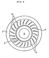
- Fig. 2 is a front view thereof;
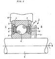
- Fig. 3 is a partial, vertical sectional view of a ball bearing sealing structure according to an embodiment (second embodiment) of the present invention referred to in the above second aspect;
- Fig. 4 is a partial front view of an annular plate used in a ball bearing sealing structure according to an embodiment (third embodiment) of the present invention referred to in the above third aspect;
- Fig. 5 illustrates a conventional example; and
- Fig. 6 illustrates another conventional example.
-
- A description will be given below about an embodiment (first embodiment) of the present invention referred to in the foregoing first aspect and illustrated in Figs. 1 and 2.
- In a ball bearing 1 to which the sealing structure of the first embodiment is applied, as shown in Figs. 1 and 2, a plurality of
balls 4 are inserted into and held between a raceway groove formed on the outer peripheral surface of aninner ring 2 and a raceway groove formed on the inner peripheral surface of anouter ring 3 by means of aretainer 5. On both sides of the ball bearing 1 are providedseals 6 which are formed of a rubber material and which are fitted in theouter ring 3. Ends of theseals 6 are not in contact with theinner ring 2, with a slight gap formed therebetween. Thus, the ball bearing 1 has the structure and form of a double seal/non-contact seal ball bearing. Acore material 7 is fitted in an inner surface of eachseal 6 by molding. - The ball bearing 1 is used so that the outer ring rotates. Therefore, in a device or equipment to which the ball bearing 1 is applied, the
outer ring 3 is fitted from the inside into a circular hole formed in awall 8 of a component which belongs to a rotating side, while theinner ring 2 is fitted on afixed shaft 9 from the outside. - Of both spaces S and T partitioned by the ball bearing 1, the righthand space S in Fig. 1 is held at a higher pressure than the left-hand space T and, for example, can be a space for the passage of discharge fluid (say, discharge air) in a fluid machine or can be a grease storing space within a gear box of a motor-driven tool.
- As to the
seal 6 fitted in theouter ring 3 on one side of the ball bearing 1 which faces the space S, a large number ofblade projections 10 are formed radially on the outer surface of the seal. It is preferable that theblade projections 10 be formed by molding integrally with the body portion of theseal 6. Theblade projections 10 are designed to have optimum length, thickness, height and shape so that they can exert an effective pumping action on the fluid in the space S, as will be described later. Although in this first embodiment theblade projections 10 are curved, they may be formed in a rectilinear shape. - The
seals 6 fitted in theouter ring 3 on both sides of the ball bearing 1 hold grease sealed in the interior of the ball bearing so as to prevent leakage of the grease to the exterior and protect the ball bearing so as not to permit the invasion of foreign matter and dust from the exterior to the interior of the bearing. Where there is a pressure difference between both spaces S and T formed on both sides of the ball bearing 1, it is possible to let the sealing function be also exhibited partially so as to prevent flowing or leakage of fluid from the higher-pressure space S to the lower-pressure space T. - Since in this first embodiment a large number of
blade projections 10 are formed radially on the outer surface of the seal (hereinafter referred to as the "high pressure-side seal") 6 provided on one side of the ball bearing 1 which faces the higher-pressure space S, the following sealing effects can be expected in addition to the above-mentioned sealing effects. - When the
outer ring 3 rotates, theseals 6 rotate together with the outer ring, and theblade projections 10 formed on the outer surface of the high pressure-side seal 6 causes fluid (e.g., air or grease) which is in contact with the said outer surface to be scattered radially outwards from the inside (see a streamline C in Fig. 1) by virtue of a centrifugal force in an apparatus or equipment to which the ball bearing 1 is applied. That is, theblade projections 10 exhibit a pumping action for the fluid which is in contact with the outer surface of the high pressure-side seal 6. - Then, in the higher-pressure space S, the fluid present around the
inner ring 2 is scattered radially outwards, so that the fluid pressure in this region drops and the pressure difference between the fluids present near the inner ring in both spaces S and T partitioned by the ball bearing 1 decreases or reverses. The "fluid present near theinner ring 2" mainly indicates the fluid present in a side region of theinner ring 2 which includes a portion facing the gap formed between the end of eachseal 6 and the outer peripheral surface of theinner ring 2 and on which the pumping action of theblade projections 10 is exerted. interior of the bearing. Where there is a pressure difference between both spaces S and T formed on both sides of the ball bearing 1, it is possible to let the sealing function be also exhibited partially so as to prevent flowing or leakage of fluid from the higher-pressure space S to the lower-pressure space T. - Since in this first embodiment a large number of
blade projections 10 are formed radially on the outer surface of the seal (hereinafter referred to as the "high pressure-side seal") 6 provided on one side of the ball bearing 1 which faces the higher-pressure space S, the following sealing effects can be expected in addition to the above-mentioned sealing effects. - When the
outer ring 3 rotates, theseals 6 rotate together with the outer ring, and theblade projections 10 formed on the outer surface of the high pressure-side seal 6 causes fluid (e.g., air or grease) which is in contact with the said outer surface to be scattered radially outwards from the inside (see a streamline C in Fig. 1) by virtue of a centrifugal force in an apparatus or equipment to which the ball bearing 1 is applied. That is, theblade projections 10 exhibit a pumping action for the fluid which is in contact with the outer surface of the high pressure-side seal 6. - Then, in the higher-pressure space S, the fluid present around the
inner ring 2 is scattered radially outwards, so that the fluid pressure in this region drops and the pressure difference between the fluids present near the inner ring in both spaces S and T partitioned by the ball bearing 1 decreases or reverses. The "fluid present near theinner ring 2" mainly indicates the fluid present in a side region of theinner ring 2 which includes a portion facing the gap formed between the end of eachseal 6 and the outer peripheral surface of theinner ring 2 and on which the pumping action of theblade projections 10 is exerted. - As a result, undesirable flowing or leakage of fluid from the higher pressure space S to the lower-pressure space T through the ball bearing 1 is suppressed and the amount of such flowing or leaking fluid is decreased remarkably, whereby the ball bearing 1 can exhibit a high sealing performance. Where grease is sealed in the ball bearing 1, leakage of the grease to the lower-pressure space T is suppressed and the amount of leaking grease is greatly decreased, permitting the ball bearing 1 to exhibit a high sealing performance.
- Flowing or leakage of fluid from the higher-pressure space S to the lower-pressure space T through the ball bearing 1 occurs mainly through the gap between the inner and
outer rings inner ring 2 and the fixedshaft 9. - In this first embodiment the
seal 6 may be substituted by a shield andsuch blade projections 10 as described above may be formed on an outer surface of the shield. Also in this case the ball bearing 1 can exhibit a high sealing performance. - The material of each
seal 6 or shield and how to form it are not specially limited. There may be adopted any of the following known materials (metals, plastics, thermoplastic elastomers, and synthetic rubbers) and known forming methods. - As examples of metallic materials are mentioned cold rolled steel plate, stainless steel, spring steel, aluminum alloy, and copper alloy.
- As examples of plastics are mentioned such thermoplastic resins as polyamide, polyacetal, polybutyrene terephthalate, polyethylene terephthalate, polycarbonate, and polyimide resins.
- As examples of thermoplastic elastomers are mentioned polyamide, polyester, polyurethane, polyolefine, polystyrene, and polyvinyl chloride elastomers.
- As examples of synthetic rubbers are mentioned nitrile, acrylic, silicone, fluorine-containing, and ethylene-propylene rubbers.
- As suitable methods for forming a metallic shield and a reinforcing ring are mentioned plastic working methods such as press working.
- As examples of the method for forming a seal or a member as a constituent of the seal using a plastic or a thermoplastic elastomer there are mentioned injection molding, compression molding, and transfer molding.
- Also as to the material of the inner and
outer rings - The following description is now provided about an embodiment (second embodiment) of the present invention referred to in the foregoing second aspect which is illustrated in Fig. 3.
- Fig. 3 is a partial, vertical sectional view of a ball bearing sealing structure according to the second embodiment, in which the same portions as in the ball bearing sealing structure of the first embodiment are identified by the same reference numerals as in the first embodiment.
- As shown in Fig. 3, the sealing structure of the ball bearing 1 in this second embodiment is different in structure from the ball bearing sealing structure of the first embodiment only in that an
annular plate 11 is mounted on the shaft (rotary shaft) 9 with theinner ring 2 fitted thereon, at a position relatively close to theblade projections 10. Regarding how to use, a difference is recognized only in that the ball bearing 1 in this second embodiment is used under rotation of theinner ring 2. - In the above points the ball bearing sealing structure of the second embodiment is different from that of the first embodiment, but there is no other difference between the two, so detailed explanations will here be omitted.
- Since the second embodiment is constructed as above, the following sealing effects can be obtained.
- As the
inner ring 2 rotates, theannular plate 11 rotates together with theinner ring 2 through therotary shaft 9. Then, in a device or equipment to which the ball bearing 1 is applied, the fluid present in the region sandwiched between theannular plate 11 and the ball bearing 1 is pulled by virtue of a viscous force and is made to rotate together with theannular plate 11, so that the fluid present in this region and theblade projections 10 formed on the outer surface of the high pressure-side seal 6 perform a relative rotational motion, and theblade projections 10 cause the fluid (air or grease) which is in contact with the outer surface of the high pressure-side seal 6 in this region to be scattered radially outwards from the inside by virtue of a centrifugal force. At the same time, to make up for the fluid thus scattered, there is created a fluid flow advancing from the outer periphery of theannular plate 11 toward the center thereof along the inner surface of the annular plate 11 (see a streamline D in Fig. 3). That is, theblade projections 10 exhibit a pumping action for the fluid which is in contact with the outer surface of theseal 6. - Consequently, in the higher-pressure space S out of both spaces S and T partitioned by the ball bearing 1, the fluid present near the
inner ring 2 is scattered radially outwards, the fluid pressure in this region (the region near theinner ring 2 and sandwiched between theannular plate 11 and the ball bearing 1) drops and the difference in pressure between the fluids present near theinner ring 2 in both spaces S and T partitioned by the ball bearing 1 decreases or reverses. - As a result, undesirable flowing or leakage of fluid from the higher-pressure space S to the lower-pressure space T through the ball bearing 1 is suppressed and the amount of such flowing or leaking fluid is decreased to a remarkable extent, thus permitting the ball bearing 1 to exhibit a high sealing performance. Where grease is sealed in the ball bearing, leakage of the grease to the lower-pressure space T is suppressed and the amount of such leaking grease is greatly reduced, whereby the ball bearing 1 can exhibit a high sealing performance.
- Also in this second embodiment the
seal 6 may be substituted by a shield, and even ifsuch blade projections 10 as described above are formed on the outer surface of the shield, the ball bearing 1 can exhibit a high sealing performance to the same extent as above. - Description is now directed to an embodiment (third embodiment) of the present invention referred to in the foregoing third aspect which is illustrated in Fig. 4.
- Fig. 4 is a front view showing a portion of an annular plate used in a ball bearing sealing structure according to this third embodiment, in which the same portions as in the ball bearing sealing structure of the previous second embodiment are identified by the same reference numerals as in the second embodiment.
- In the sealing structure of a ball bearing 1 according to this third embodiment, as shown in Fig. 4, a plurality of through
holes 12 are formed circumferentially in the vicinity of an inner peripheral edge of theannular plate 11 used therein. The plural throughholes 12 may be formed by cutting off the inner peripheral edge of theannular plate 11 each in a semicircular shape. The size of each throughhole 12 is set to an appropriate size in relation to the pumping action of theblade projections 10. - Although the ball bearing sealing structure of the third embodiment is different in the above point from the ball bearing sealing structure of the previous second embodiment, there is no other different point between the two, so a detailed description will here be omitted.
- Since the third embodiment is constructed as above, it is not necessary to let fluid reciprocate within the narrow region sandwiched between the
annular plate 11 and the ball bearing 1 (see the streamline D in Fig. 3), and a high-pressure fluid is constantly replenished under reduced pressure into a fluid pressure dropping portion in the region near theinner ring 2 included in the said narrow region through the plural throughholes 12 from the higher-pressure space S located on the side opposite to the ball bearing 1 with respect to theannular plate 11, whereby it is possible to establish a circulation path free of any difficulty in flowing for the fluid which undergoes the pumping action. In this way the pumping action of theblade projections 10 can be allowed to proceed smoothly and the foregoing effects attained by the second embodiment can be further promoted. - Although the ball bearings 1 described in the above first to third embodiments have the structure and form of a double-seal/non-contact type seal ball bearing or a double-shield/non-contact type shield ball bearing, no limitation is made thereto. They may be of various other structures and forms, including double-seal/contact type, single-seal/non-contact type, and single-seal/contact type seal ball bearings, double-shield/ contact type, single-shield/non-contact type, and single-shield/contact type shield ball bearings, seal ball bearings having a seal of a double structure, and shield ball bearings having a shield of a double structure.
- Various changes and modifications may be made within the scope not departing from the gist of the present invention.
Claims (3)
- A sealing structure of a ball bearing wherein a seal or a shield is provided on at least one side of the ball bearing and the ball bearing is used under rotation of an outer ring, characterized in that:a multitude of blade projections are formed radially on an outer surface of said seal or said shield provided on one side of said ball bearing.
- A sealing structure of a ball bearing wherein a seal or a shield is provided on at least one side of the ball bearing and the ball bearing is used under rotation of an inner ring, characterized in that:a multitude of blade projections are formed radially on an outer surface of said seal or said shield provided on one side of said ball bearing; andan annular plate is mounted on a shaft with said inner ring fitted thereon at a position relatively close to said blade projections.
- A sealing structure of a ball bearing according to claim 2, wherein a plurality of through holes are formed circumferentially on or near an inner peripheral edge of said annular plate.
Applications Claiming Priority (2)
| Application Number | Priority Date | Filing Date | Title |
|---|---|---|---|
| JP2001059751 | 2001-03-05 | ||
| JP2001059751A JP2002266880A (en) | 2001-03-05 | 2001-03-05 | Seal structure of ball bearing |
Publications (3)
| Publication Number | Publication Date |
|---|---|
| EP1239173A2 true EP1239173A2 (en) | 2002-09-11 |
| EP1239173A3 EP1239173A3 (en) | 2004-09-15 |
| EP1239173B1 EP1239173B1 (en) | 2006-08-09 |
Family
ID=18919269
Family Applications (1)
| Application Number | Title | Priority Date | Filing Date |
|---|---|---|---|
| EP02004781A Expired - Lifetime EP1239173B1 (en) | 2001-03-05 | 2002-03-01 | Sealing means for a rolling contact bearing |
Country Status (5)
| Country | Link |
|---|---|
| US (1) | US6715765B2 (en) |
| EP (1) | EP1239173B1 (en) |
| JP (1) | JP2002266880A (en) |
| AT (1) | ATE335937T1 (en) |
| DE (1) | DE60213694T2 (en) |
Cited By (11)
| Publication number | Priority date | Publication date | Assignee | Title |
|---|---|---|---|---|
| EP1450058A2 (en) * | 2003-02-18 | 2004-08-25 | Koyo Seiko Co., Ltd. | Rolling bearing with ring made of ceramics |
| EP1493935A1 (en) * | 2003-06-30 | 2005-01-05 | Koyo Seiko Co., Ltd. | Rolling bearing |
| DE10324849B4 (en) * | 2003-06-02 | 2005-12-22 | Minebea Co., Ltd. | Electric motor with a shaft seal for sealing a motor shaft of the electric motor |
| EP1719927A1 (en) * | 2004-02-18 | 2006-11-08 | Jtekt Corporation | Rolling bearing for supercharger |
| EP1903231A2 (en) * | 2006-09-20 | 2008-03-26 | HILTI Aktiengesellschaft | Journal bearing gasket |
| WO2009142574A1 (en) * | 2008-05-23 | 2009-11-26 | Scania Cv Ab | Wheel suspension device |
| EP2180214A1 (en) * | 2008-10-24 | 2010-04-28 | Makita Corporation | Sealing device for gear chamber |
| WO2010112380A1 (en) * | 2009-04-03 | 2010-10-07 | Schaeffler Technologies Gmbh & Co. Kg | Release bearing having concave sealing lip |
| WO2012171719A1 (en) * | 2011-06-17 | 2012-12-20 | Schaeffler Technologies AG & Co. KG | Air cooling for rolling contact bearings |
| GB2529654A (en) * | 2014-08-28 | 2016-03-02 | Skf Ab | Bearing |
| GB2602029A (en) * | 2020-12-15 | 2022-06-22 | Edwards S R O | A pump and a bearing assembly for a pump |
Families Citing this family (18)
| Publication number | Priority date | Publication date | Assignee | Title |
|---|---|---|---|---|
| DE102004040622A1 (en) * | 2004-08-21 | 2006-02-23 | Voith Paper Patent Gmbh | doctor device |
| JP4639868B2 (en) * | 2005-03-11 | 2011-02-23 | 日本精工株式会社 | Rolling bearing with seal ring |
| EP1707856A1 (en) * | 2005-04-01 | 2006-10-04 | Cross Manufacturing Company (1938) Limited | Brush seals |
| JP4456062B2 (en) * | 2005-12-16 | 2010-04-28 | 株式会社酉島製作所 | Fluid machinery sealing device |
| JP2007192356A (en) * | 2006-01-20 | 2007-08-02 | Nsk Ltd | Sealing device for rolling bearing |
| GB2440544A (en) * | 2006-08-02 | 2008-02-06 | Rolls Royce Plc | Bearing discharge flow control arrangement |
| WO2008129807A1 (en) * | 2007-03-28 | 2008-10-30 | Ntn Corporation | Rotation sensor |
| JP5063209B2 (en) * | 2007-06-20 | 2012-10-31 | Ntn株式会社 | Rotation detection sensor / fixing member mounting body |
| DE102008036623A1 (en) * | 2008-08-06 | 2010-02-11 | Oerlikon Leybold Vacuum Gmbh | Use of a roller bearing for mounting rotating components in Vakuumeinirchtungen and vacuum device |
| WO2010018661A1 (en) * | 2008-08-11 | 2010-02-18 | Ntn株式会社 | Rotation sensor |
| US20100201072A1 (en) * | 2009-02-06 | 2010-08-12 | Wians Jeffrey A | One piece shaft seal apparatus and method |
| US8297949B1 (en) * | 2009-02-17 | 2012-10-30 | Mancl Scott C | Bearing seal for a wet vacuum motor |
| CN102371573A (en) * | 2010-08-10 | 2012-03-14 | 南京德朔实业有限公司 | Electric tool |
| JP2013002687A (en) * | 2011-06-14 | 2013-01-07 | Sumitomo Heavy Ind Ltd | Cold storage refrigerator |
| US9377054B2 (en) | 2014-05-19 | 2016-06-28 | Seagate Technology Llc | Fluid seal for a rotating assembly |
| US10480520B2 (en) | 2016-06-16 | 2019-11-19 | Scott C. Mancl | Motor-driven fan with an assembly for minimizing vibration and strain |
| CN106704381A (en) * | 2016-12-15 | 2017-05-24 | 碎得机械(北京)有限公司 | Split deep groove ball bearing |
| JP7266992B2 (en) * | 2018-11-12 | 2023-05-01 | Nok株式会社 | Airflow generating structure and sealing structure |
Family Cites Families (23)
| Publication number | Priority date | Publication date | Assignee | Title |
|---|---|---|---|---|
| US4091988A (en) * | 1976-06-21 | 1978-05-30 | Albert G. Bodine | Centrifugal trap for solid particles |
| US4181312A (en) * | 1978-05-11 | 1980-01-01 | Douglas Frederick | Slinger device |
| JPS55113177A (en) * | 1979-02-23 | 1980-09-01 | Nec Corp | Air ventilating mechanism of magnetic disk unit |
| US4223749A (en) * | 1979-03-15 | 1980-09-23 | Bodine Albert G | Rotary earth boring drill bit with centrifugal foreign particle barrier device |
| DE2930462C2 (en) * | 1979-07-27 | 1983-11-03 | Fa. Carl Freudenberg, 6940 Weinheim | Mud seal |
| JPS56108021A (en) * | 1980-01-31 | 1981-08-27 | Osaka Cement Kk | Utilizing method of bamboo as industrial fuel |
| US4446933A (en) * | 1982-03-29 | 1984-05-08 | Bodine Albert G | Rotary earth boring drill bit with centrifugal lubrication system |
| US4808012A (en) * | 1987-03-23 | 1989-02-28 | The Timken Company | Flap seal for anti-friction bearings |
| JPH01115070U (en) * | 1988-01-29 | 1989-08-02 | ||
| IT1256785B (en) * | 1992-01-28 | 1995-12-15 | Skf Ind Spa | SEALING COMPLEX WITH A SENSOR DEVICE ON BOARD, FOR A ROLLING BEARING. |
| DE4215905A1 (en) * | 1992-05-14 | 1993-11-18 | Skf Gmbh | High-speed ball- or roller-bearing seal - has washer inclined to bearing axis and with spiral-type protrusions at inside |
| US5242229A (en) * | 1992-11-25 | 1993-09-07 | The Torrington Company | Sealing structure for standardized bearing ring |
| DE4329398A1 (en) * | 1993-01-13 | 1994-07-14 | Ford Werke Ag | Roller bearing with filter discs between inner and outer race |
| US5560715A (en) * | 1995-04-26 | 1996-10-01 | The Torrington Company | Rolling element bearing with shield |
| JP2917115B2 (en) * | 1995-11-20 | 1999-07-12 | ミネベア株式会社 | Rolling bearing |
| EP0785369B1 (en) * | 1996-01-22 | 2004-03-24 | Nsk Ltd | Rolling bearing unit with tone wheel |
| JP3740219B2 (en) * | 1996-07-05 | 2006-02-01 | 光洋精工株式会社 | Rolling bearing sealing device |
| GB9615941D0 (en) * | 1996-07-30 | 1996-09-11 | Timken Co | Combined bearing and sensor assembly |
| US5979903A (en) * | 1997-12-04 | 1999-11-09 | Sanford Acquisition Company | Translucent slinger with centrifugal seal |
| JPH11230179A (en) * | 1998-02-19 | 1999-08-27 | Nippon Seiko Kk | Rolling bearing |
| FR2781850B1 (en) * | 1998-07-29 | 2000-09-08 | Roulements Soc Nouvelle | BEARING FOR DRAWING CHAIN |
| JP2001263359A (en) * | 2000-03-16 | 2001-09-26 | Fuji Heavy Ind Ltd | Seal device for bearing |
| JP2002227859A (en) * | 2001-01-31 | 2002-08-14 | Koyo Seiko Co Ltd | Seal device of bearing for axle |
-
2001
- 2001-03-05 JP JP2001059751A patent/JP2002266880A/en active Pending
-
2002
- 2002-03-01 DE DE60213694T patent/DE60213694T2/en not_active Expired - Lifetime
- 2002-03-01 EP EP02004781A patent/EP1239173B1/en not_active Expired - Lifetime
- 2002-03-01 AT AT02004781T patent/ATE335937T1/en not_active IP Right Cessation
- 2002-03-04 US US10/087,219 patent/US6715765B2/en not_active Expired - Fee Related
Non-Patent Citations (1)
| Title |
|---|
| None |
Cited By (18)
| Publication number | Priority date | Publication date | Assignee | Title |
|---|---|---|---|---|
| US7431511B2 (en) | 2003-02-18 | 2008-10-07 | Koyo Seiko Co., Ltd. | Rolling bearing |
| EP1450058A3 (en) * | 2003-02-18 | 2005-12-14 | Koyo Seiko Co., Ltd. | Rolling bearing with ring made of ceramics |
| EP1450058A2 (en) * | 2003-02-18 | 2004-08-25 | Koyo Seiko Co., Ltd. | Rolling bearing with ring made of ceramics |
| DE10324849B4 (en) * | 2003-06-02 | 2005-12-22 | Minebea Co., Ltd. | Electric motor with a shaft seal for sealing a motor shaft of the electric motor |
| EP1493935A1 (en) * | 2003-06-30 | 2005-01-05 | Koyo Seiko Co., Ltd. | Rolling bearing |
| US7237961B2 (en) | 2003-06-30 | 2007-07-03 | Koyo Seiko Co., Ltd. | Rolling bearing |
| EP1719927A1 (en) * | 2004-02-18 | 2006-11-08 | Jtekt Corporation | Rolling bearing for supercharger |
| EP1719927A4 (en) * | 2004-02-18 | 2007-09-26 | Jtekt Corp | Rolling bearing for supercharger |
| EP1903231A2 (en) * | 2006-09-20 | 2008-03-26 | HILTI Aktiengesellschaft | Journal bearing gasket |
| EP1903231A3 (en) * | 2006-09-20 | 2009-04-29 | HILTI Aktiengesellschaft | Journal bearing gasket |
| WO2009142574A1 (en) * | 2008-05-23 | 2009-11-26 | Scania Cv Ab | Wheel suspension device |
| EP2180214A1 (en) * | 2008-10-24 | 2010-04-28 | Makita Corporation | Sealing device for gear chamber |
| CN101725702B (en) * | 2008-10-24 | 2015-04-08 | 株式会社牧田 | Sealing device for gear chamber |
| WO2010112380A1 (en) * | 2009-04-03 | 2010-10-07 | Schaeffler Technologies Gmbh & Co. Kg | Release bearing having concave sealing lip |
| WO2012171719A1 (en) * | 2011-06-17 | 2012-12-20 | Schaeffler Technologies AG & Co. KG | Air cooling for rolling contact bearings |
| GB2529654A (en) * | 2014-08-28 | 2016-03-02 | Skf Ab | Bearing |
| US9638253B2 (en) | 2014-08-28 | 2017-05-02 | Aktiebolaget Skf | Bearing |
| GB2602029A (en) * | 2020-12-15 | 2022-06-22 | Edwards S R O | A pump and a bearing assembly for a pump |
Also Published As
| Publication number | Publication date |
|---|---|
| EP1239173B1 (en) | 2006-08-09 |
| DE60213694T2 (en) | 2007-02-22 |
| US20020130470A1 (en) | 2002-09-19 |
| DE60213694D1 (en) | 2006-09-21 |
| JP2002266880A (en) | 2002-09-18 |
| US6715765B2 (en) | 2004-04-06 |
| EP1239173A3 (en) | 2004-09-15 |
| ATE335937T1 (en) | 2006-09-15 |
Similar Documents
| Publication | Publication Date | Title |
|---|---|---|
| EP1239173B1 (en) | Sealing means for a rolling contact bearing | |
| US6336638B1 (en) | Radial shaft seal | |
| US7201685B2 (en) | Pulley unit | |
| JP6033996B1 (en) | Sealing device | |
| US20030189294A1 (en) | Sliding element | |
| US10794428B2 (en) | Sealing device and hub bearing | |
| MX2007000655A (en) | Lip type end face sealing device. | |
| US20120009077A1 (en) | Scroll Fluid Machine | |
| US4655617A (en) | Sealed rolling bearing with a flow reducing grease passage | |
| US10260635B2 (en) | Sealing device | |
| MX2013002912A (en) | Fluid seal assembly. | |
| CN103238012A (en) | Sealing device and sealing structure | |
| JP6899456B2 (en) | Sealing device | |
| WO2017094599A1 (en) | Seal device | |
| JP6745609B2 (en) | Bearing with seal | |
| JPS62210282A (en) | Shift seal device of oil-free fluid machine | |
| JP5865960B2 (en) | Compressor | |
| US6659747B2 (en) | Shaft seal structure of vacuum pumps | |
| JP2007046767A (en) | Bearing for cleaner motor | |
| JPS6340650Y2 (en) | ||
| US11692591B2 (en) | Sealing device for a bearing unit | |
| JPH0673544U (en) | Oil seal | |
| JPH0673545U (en) | Oil seal | |
| KR102635743B1 (en) | Leak-proof bearing assembly | |
| JP2002235751A (en) | Rolling bearing |
Legal Events
| Date | Code | Title | Description |
|---|---|---|---|
| PUAI | Public reference made under article 153(3) epc to a published international application that has entered the european phase |
Free format text: ORIGINAL CODE: 0009012 |
|
| AK | Designated contracting states |
Kind code of ref document: A2 Designated state(s): AT BE CH CY DE DK ES FI FR GB GR IE IT LI LU MC NL PT SE TR |
|
| AX | Request for extension of the european patent |
Free format text: AL;LT;LV;MK;RO;SI |
|
| PUAL | Search report despatched |
Free format text: ORIGINAL CODE: 0009013 |
|
| AK | Designated contracting states |
Kind code of ref document: A3 Designated state(s): AT BE CH CY DE DK ES FI FR GB GR IE IT LI LU MC NL PT SE TR |
|
| AX | Request for extension of the european patent |
Extension state: AL LT LV MK RO SI |
|
| 17P | Request for examination filed |
Effective date: 20050208 |
|
| AKX | Designation fees paid |
Designated state(s): AT BE CH CY DE DK ES FI FR GB GR IE IT LI LU MC NL PT SE TR |
|
| 17Q | First examination report despatched |
Effective date: 20050517 |
|
| GRAP | Despatch of communication of intention to grant a patent |
Free format text: ORIGINAL CODE: EPIDOSNIGR1 |
|
| GRAS | Grant fee paid |
Free format text: ORIGINAL CODE: EPIDOSNIGR3 |
|
| GRAA | (expected) grant |
Free format text: ORIGINAL CODE: 0009210 |
|
| AK | Designated contracting states |
Kind code of ref document: B1 Designated state(s): AT BE CH CY DE DK ES FI FR GB GR IE IT LI LU MC NL PT SE TR |
|
| PG25 | Lapsed in a contracting state [announced via postgrant information from national office to epo] |
Ref country code: IT Free format text: LAPSE BECAUSE OF FAILURE TO SUBMIT A TRANSLATION OF THE DESCRIPTION OR TO PAY THE FEE WITHIN THE PRESCRIBED TIME-LIMIT;WARNING: LAPSES OF ITALIAN PATENTS WITH EFFECTIVE DATE BEFORE 2007 MAY HAVE OCCURRED AT ANY TIME BEFORE 2007. THE CORRECT EFFECTIVE DATE MAY BE DIFFERENT FROM THE ONE RECORDED. Effective date: 20060809 Ref country code: BE Free format text: LAPSE BECAUSE OF FAILURE TO SUBMIT A TRANSLATION OF THE DESCRIPTION OR TO PAY THE FEE WITHIN THE PRESCRIBED TIME-LIMIT Effective date: 20060809 Ref country code: AT Free format text: LAPSE BECAUSE OF FAILURE TO SUBMIT A TRANSLATION OF THE DESCRIPTION OR TO PAY THE FEE WITHIN THE PRESCRIBED TIME-LIMIT Effective date: 20060809 Ref country code: NL Free format text: LAPSE BECAUSE OF FAILURE TO SUBMIT A TRANSLATION OF THE DESCRIPTION OR TO PAY THE FEE WITHIN THE PRESCRIBED TIME-LIMIT Effective date: 20060809 Ref country code: FI Free format text: LAPSE BECAUSE OF FAILURE TO SUBMIT A TRANSLATION OF THE DESCRIPTION OR TO PAY THE FEE WITHIN THE PRESCRIBED TIME-LIMIT Effective date: 20060809 |
|
| REG | Reference to a national code |
Ref country code: GB Ref legal event code: FG4D |
|
| REG | Reference to a national code |
Ref country code: CH Ref legal event code: EP Ref country code: CH Ref legal event code: NV Representative=s name: GERHARD H. ULRICH PATENTANWALT |
|
| REG | Reference to a national code |
Ref country code: IE Ref legal event code: FG4D |
|
| REF | Corresponds to: |
Ref document number: 60213694 Country of ref document: DE Date of ref document: 20060921 Kind code of ref document: P |
|
| PG25 | Lapsed in a contracting state [announced via postgrant information from national office to epo] |
Ref country code: SE Free format text: LAPSE BECAUSE OF FAILURE TO SUBMIT A TRANSLATION OF THE DESCRIPTION OR TO PAY THE FEE WITHIN THE PRESCRIBED TIME-LIMIT Effective date: 20061109 Ref country code: DK Free format text: LAPSE BECAUSE OF FAILURE TO SUBMIT A TRANSLATION OF THE DESCRIPTION OR TO PAY THE FEE WITHIN THE PRESCRIBED TIME-LIMIT Effective date: 20061109 |
|
| PG25 | Lapsed in a contracting state [announced via postgrant information from national office to epo] |
Ref country code: ES Free format text: LAPSE BECAUSE OF FAILURE TO SUBMIT A TRANSLATION OF THE DESCRIPTION OR TO PAY THE FEE WITHIN THE PRESCRIBED TIME-LIMIT Effective date: 20061120 |
|
| PG25 | Lapsed in a contracting state [announced via postgrant information from national office to epo] |
Ref country code: PT Free format text: LAPSE BECAUSE OF FAILURE TO SUBMIT A TRANSLATION OF THE DESCRIPTION OR TO PAY THE FEE WITHIN THE PRESCRIBED TIME-LIMIT Effective date: 20070109 |
|
| NLV1 | Nl: lapsed or annulled due to failure to fulfill the requirements of art. 29p and 29m of the patents act | ||
| ET | Fr: translation filed | ||
| PLBE | No opposition filed within time limit |
Free format text: ORIGINAL CODE: 0009261 |
|
| STAA | Information on the status of an ep patent application or granted ep patent |
Free format text: STATUS: NO OPPOSITION FILED WITHIN TIME LIMIT |
|
| 26N | No opposition filed |
Effective date: 20070510 |
|
| GBPC | Gb: european patent ceased through non-payment of renewal fee |
Effective date: 20070301 |
|
| PG25 | Lapsed in a contracting state [announced via postgrant information from national office to epo] |
Ref country code: MC Free format text: LAPSE BECAUSE OF NON-PAYMENT OF DUE FEES Effective date: 20070331 Ref country code: IE Free format text: LAPSE BECAUSE OF NON-PAYMENT OF DUE FEES Effective date: 20070301 |
|
| PG25 | Lapsed in a contracting state [announced via postgrant information from national office to epo] |
Ref country code: GB Free format text: LAPSE BECAUSE OF NON-PAYMENT OF DUE FEES Effective date: 20070301 Ref country code: GR Free format text: LAPSE BECAUSE OF FAILURE TO SUBMIT A TRANSLATION OF THE DESCRIPTION OR TO PAY THE FEE WITHIN THE PRESCRIBED TIME-LIMIT Effective date: 20061110 |
|
| PG25 | Lapsed in a contracting state [announced via postgrant information from national office to epo] |
Ref country code: LU Free format text: LAPSE BECAUSE OF NON-PAYMENT OF DUE FEES Effective date: 20070301 Ref country code: CY Free format text: LAPSE BECAUSE OF FAILURE TO SUBMIT A TRANSLATION OF THE DESCRIPTION OR TO PAY THE FEE WITHIN THE PRESCRIBED TIME-LIMIT Effective date: 20060809 |
|
| PG25 | Lapsed in a contracting state [announced via postgrant information from national office to epo] |
Ref country code: TR Free format text: LAPSE BECAUSE OF FAILURE TO SUBMIT A TRANSLATION OF THE DESCRIPTION OR TO PAY THE FEE WITHIN THE PRESCRIBED TIME-LIMIT Effective date: 20060809 |
|
| PGFP | Annual fee paid to national office [announced via postgrant information from national office to epo] |
Ref country code: CH Payment date: 20100323 Year of fee payment: 9 |
|
| PGFP | Annual fee paid to national office [announced via postgrant information from national office to epo] |
Ref country code: FR Payment date: 20100324 Year of fee payment: 9 |
|
| PGFP | Annual fee paid to national office [announced via postgrant information from national office to epo] |
Ref country code: DE Payment date: 20100312 Year of fee payment: 9 |
|
| REG | Reference to a national code |
Ref country code: CH Ref legal event code: PL |
|
| REG | Reference to a national code |
Ref country code: FR Ref legal event code: ST Effective date: 20111130 |
|
| PG25 | Lapsed in a contracting state [announced via postgrant information from national office to epo] |
Ref country code: DE Free format text: LAPSE BECAUSE OF NON-PAYMENT OF DUE FEES Effective date: 20111001 Ref country code: LI Free format text: LAPSE BECAUSE OF NON-PAYMENT OF DUE FEES Effective date: 20110331 Ref country code: FR Free format text: LAPSE BECAUSE OF NON-PAYMENT OF DUE FEES Effective date: 20110331 Ref country code: CH Free format text: LAPSE BECAUSE OF NON-PAYMENT OF DUE FEES Effective date: 20110331 |
|
| REG | Reference to a national code |
Ref country code: DE Ref legal event code: R119 Ref document number: 60213694 Country of ref document: DE Effective date: 20111001 |