EP1239158A2 - Scroll type compressor - Google Patents
Scroll type compressor Download PDFInfo
- Publication number
- EP1239158A2 EP1239158A2 EP02004861A EP02004861A EP1239158A2 EP 1239158 A2 EP1239158 A2 EP 1239158A2 EP 02004861 A EP02004861 A EP 02004861A EP 02004861 A EP02004861 A EP 02004861A EP 1239158 A2 EP1239158 A2 EP 1239158A2
- Authority
- EP
- European Patent Office
- Prior art keywords
- scroll
- base plate
- wall
- movable
- distal end
- Prior art date
- Legal status (The legal status is an assumption and is not a legal conclusion. Google has not performed a legal analysis and makes no representation as to the accuracy of the status listed.)
- Withdrawn
Links
Images


Classifications
-
- F—MECHANICAL ENGINEERING; LIGHTING; HEATING; WEAPONS; BLASTING
- F04—POSITIVE - DISPLACEMENT MACHINES FOR LIQUIDS; PUMPS FOR LIQUIDS OR ELASTIC FLUIDS
- F04C—ROTARY-PISTON, OR OSCILLATING-PISTON, POSITIVE-DISPLACEMENT MACHINES FOR LIQUIDS; ROTARY-PISTON, OR OSCILLATING-PISTON, POSITIVE-DISPLACEMENT PUMPS
- F04C18/00—Rotary-piston pumps specially adapted for elastic fluids
- F04C18/02—Rotary-piston pumps specially adapted for elastic fluids of arcuate-engagement type, i.e. with circular translatory movement of co-operating members, each member having the same number of teeth or tooth-equivalents
- F04C18/0207—Rotary-piston pumps specially adapted for elastic fluids of arcuate-engagement type, i.e. with circular translatory movement of co-operating members, each member having the same number of teeth or tooth-equivalents both members having co-operating elements in spiral form
- F04C18/0246—Details concerning the involute wraps or their base, e.g. geometry
- F04C18/0269—Details concerning the involute wraps
Definitions
- the present invention relates to a scroll type compressor and more particularly to structure of a fixed scroll member and a movable scroll member which constitute a compression mechanism in a volute shape.
- the scroll type compressor has a housing in which the fixed scroll member and the movable scroll member are provided.
- the fixed scroll member has a fixed scroll base plate and a fixed scroll wall that extends from the fixed scroll base plate.
- the movable scroll member has a movable scroll base plate and a movable scroll wall that extends from the movable scroll base plate. Each scroll wall is engaged with each other.
- the fixed scroll member and the movable scroll member cooperatively form a plurality of compression chambers as a compression region. As the movable scroll member orbits about an axis of the fixed scroll member, the compression chambers move radially inward while their volume decreases.
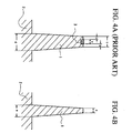
- a scroll wall 1 was conventionally created in a taper shape from a joining portion to a base plate 2 toward a distal end of the scroll wall 1.
- the scroll wall 1 is strengthened against bending moment. Therefore, clearance between the scroll walls 1 was effectively restrained from increasing.
- a tip seal 3 slides the surface of the opposing base plate 2 to ensure sealing performance in the clearance between the distal end of the scroll wall 1 and the opposing base plate 2.
- the compressor including the scroll wall 1 shown in FIG. 4A has less capacity in the compression chambers than that of FIG. 4B, because of an increase in thickness of the scroll wall 1 provided with the tip seal 3.
- the configuration of the compressor is inevitably increased in size.
- the present invention addresses a scroll type compressor which is hard, compact and lightweight with high quality sealing performance.
- a scroll type compressor has a fixed scroll member and a movable scroll member.
- the fixed scroll member has a fixed scroll base plate and a fixed scroll wall extending from the fixed scroll base plate.
- the movable scroll member has a movable scroll base plate and a movable scroll wall extending from the movable scroll base plate.
- the fixed scroll member and the movable scroll member cooperatively form a compression region.
- the movable scroll member orbits relative to the fixed scroll member to compress refrigerant in the compression region.
- Each scroll wall is formed in a taper shape from each base plate toward each distal end of the scroll wall. The distal end is non-contact with the opposing scroll base plate. Clearance between the distal end and the opposing scroll base plate is less than or equal to the limit clearance value which maintains airtight performance between the distal end and the opposing scroll base plate.
- a front housing 30, a center housing 31 and a rear housing 32 are connected to form a configuration of the compressor.
- a fixed scroll member 35 is integrally formed with the center housing 31.
- the fixed scroll member 35 has a fixed scroll base plate 33 and a fixed scroll wall 34 that extends from the fixed scroll base plate 33.
- An inlet 36 for introducing refrigerant is also formed in the center housing 31 and is connected to an external refrigerant circuit.
- a movable scroll member 39 is accommodated in a space defined by the center housing 31 and the front housing 30.
- the movable scroll member 39 has a movable scroll base plate 37 and a movable scroll wall 38 that extends from the movable scroll base plate 37.
- the fixed scroll wall 34 and the movable scroll wall 38 engage with each other.
- a plurality of compression chambers 40 is defined as a compression region between the fixed scroll member 35 and the movable scroll member 39.
- a discharge hole 42 is formed substantially at the center of the fixed scroll base plate 33. Compressed refrigerant in the compression chambers 40 is discharged into a discharge chamber 41 defined between the center housing 31 and the rear housing 32 through the discharge hole 42.
- An outlet 43 is formed in the rear housing 32 to flow refrigerant in the discharge chamber 41 into the external refrigerant circuit.
- one end of a drive shaft 45 is rotatably supported in the front housing 30 by bearing 44 and the other end of the drive shaft 45 extends outside of the configuration of the compressor.
- a crankshaft 46 is mounted on one end of the drive shaft 45.
- the crankshaft 46 is received by a bushing 47, which is inserted in a boss 48 of the movable scroll member 39.
- a self rotation preventing mechanism 49 prevents the movable scroll member 39 from rotating about its axis, while allowing the movable scroll member 39 to orbit about an axis of the fixed scroll member 35.
- the fixed scroll wall 34 and the movable scroll wall 38 are respectively formed in a taper shape from portions joining to the scroll base plates 33 and 37 toward the respective distal ends.
- the fixed scroll wall 34 has a pair of side surfaces 34a and 34b which incline by angles of ⁇ 1 and ⁇ 2 with respect to the direction of an axis of the drive shaft 45 (which is perpendicular to the scroll base plates 33 and 37), respectively.
- the movable scroll wall 38 has a pair of side surfaces 38a and 38b which incline by angles of ⁇ 3 and ⁇ 4 with respect to the direction of the axis of the drive shaft 45 (which is perpendicular to the scroll base plates 33 and 37), respectively.
- the side surfaces 34b and 38a which face each other are equal in inclination angle. That is, ⁇ 2 equals ⁇ 3 .
- the side surfaces 34a and 38b which face each other are also equal in inclination angle. That is, ⁇ 1 equals ⁇ 4 .
- ⁇ 1 equals ⁇ 2 .
- ⁇ 3 also equals ⁇ 4 .
- the fixed scroll wall 34 and the movable scroll wall 38 are equal in inclination angle.
- the above inclination angle is formed not only by cutting but also by utilizing a draft upon casting.
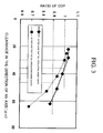
- the value of x-axis represents length of clearance G 1 and G 2 in the direction of the axis expressed by unit of micrometer or ⁇ m and the value of y-axis represents a ratio of Coefficient of Performance or COP of a compressor according to the present invention, which is not provided with the tip seal, to that of a compressor which is provided with the tip seal.
- the length of the clearance represents distance between the distal end of the scroll wall and the opposing surface of the scroll base plate.
- efficiency of load L which is required due to a heat absorption in an evaporator is generally expressed by COP as follows.
- COP Q er /L, where Q er denotes efficiency of refrigeration.
- the ratio of COP is allowable if it is more than or equal to 0.9.
- FIG. 3 reads that the length of the clearance is less than or equal to 60 ⁇ m.
- FIG. 3 reads that the length of the clearance is less than or equal to 47 ⁇ m. Accordingly, it is required that the clearance G 1 and G 2 are each less than or equal to the above upper limit value.
- the fixed scroll wall 34 and the movable scroll wall 38 are respectively formed in a taper shape from the portions joining to the scroll base plates 33 and 37 toward the respective distal ends, while having relatively sufficient thickness of the portions. Accordingly, the fixed scroll wall 34 and the movable scroll wall 38 are restrained from being deformed, thus effectively maintaining a sealing performance therebetween.
- the ratio of COP is more than or equal to 1.
- the ratio of COP is also more than or equal to 1.
- the thickness of the distal ends of the scroll walls 34 and 38 is prevented from inevitably increasing by providing the tip seal. Accordingly, the thickness of the scroll wall is determined to be minimized. In spite of the relatively sufficient thickness of the joint portion, the configuration of the compressor is not increased in size.
- the side surface 34a of the scroll wall 34 and the side surface 38b of the scroll wall 38 facing each other are equal in inclination angle.
- the side surface 34b of the scroll wall 34 and the side surface 38a of the scroll wall 38 facing each other are equal in inclination angle. Therefore, airtight constitution in the compression region is easily obtained by a draft upon casting.
- the side surfaces 34a and 34b of the scroll wall 34 are each equal in inclination angle.
- the side surfaces 38a and 38b of the scroll wall 38 are equal in inclination angle.
- these side surfaces 34a, 34b, 38a and 38b are each set to be equal in inclination angle even between the scroll members 35 and 39, molding for casting is easily manufactured.
- a scroll type compressor according to a second preferred embodiment of the present invention will be described with reference to FIG. 2.
- the side surfaces 34a, 34b of the scroll wall 34 are different in inclination angle.
- the side surfaces 38a, 38b of the scroll wall 38 are different in inclination angle. That is, inclination angles ⁇ 1 , ⁇ 2 of the side surfaces 34a, 34b of the scroll wall 34 are different from each other.
- inclination angles ⁇ 3 , ⁇ 4 of the side surfaces 38a, 38b of the scroll wall 38 are different from each other.
- side surfaces of a scroll wall are different in inclination angle.
- the scroll member is formed, for example, by casting, it may be required that the side surfaces of the scroll wall are different in draft in a casting plan. Accordingly, inclination angles of the side surfaces are predetermined differently.
- the other constitution of the second embodiment is similar to the constitution of the first embodiment, and the overlapped explanation is omitted.
- each pair of side surfaces 34a, 38b and 34b, 38a of the scroll walls 34 and 38 facing each other is equal in inclination angle even if the side surfaces 34a, 34b and 38a, 38b of the scroll walls 34 and 38 are each different in inclination angle, sealing performance in the compression chambers 40 is ensured. Thus, compression cycle in the compression chambers 40 is performed without obstruction.
- the scroll type compressor according to the above embodiments has the drive shaft which protrudes outside of the configuration of the compressor and is operatively connected to the external drive source such as an engine.
- the above external drive source may be built in type or canned motor type. That is, electric motor for driving the drive shaft may be installed in the compressor.
- the scroll wall since thickness of the joint portion of the scroll wall is larger than that of the distal end of the scroll wall, the scroll wall is prevented from being deformed. In addition, sealing performance is ensured in clearance between the distal end of the scroll wall and the opposing surface of the scroll base plate. Therefore, airtight performance in the compression region is, as a whole, maintained. As a result, high compressing performance is obtained. Moreover, since the distal end is not provided with the tip seal, the scroll wall has, as a whole, relatively small thickness. As a result, the scroll wall becomes compact and lightweight. Thus, various prominent effects are obtained.
- a scroll type compressor has a fixed scroll member and a movable scroll member.
- the fixed scroll member has a fixed scroll base plate and a fixed scroll wall extending from the fixed scroll base plate.
- the movable scroll member has a movable scroll base plate and a movable scroll wall extending from the movable scroll base plate.
- the fixed scroll member and the movable scroll member cooperatively form a compression region.
- the movable scroll member orbits relative to the fixed scroll member to compress refrigerant in the compression region.
- Each scroll wall is formed in a taper shape from each base plate toward each distal end of the scroll wall. The distal end is non-contact with the opposing scroll base plate. Clearance between the distal end and the opposing scroll base plate is less than or equal to the limit clearance value which maintains airtight performance.
Landscapes
- Engineering & Computer Science (AREA)
- Mechanical Engineering (AREA)
- General Engineering & Computer Science (AREA)
- Rotary Pumps (AREA)
Abstract
A scroll type compressor has a fixed scroll
member and a movable scroll member. The fixed
scroll member has a fixed scroll base plate and a
fixed scroll wall extending from the fixed scroll
base plate. The movable scroll member has a
movable scroll base plate and a movable scroll wall
extending from the movable scroll base plate. The
fixed scroll member and the movable scroll member
cooperatively form a compression region. The
movable scroll member orbits relative to the fixed
scroll member to compress refrigerant in the
compression region. Each scroll wall is formed in a
taper shape from each base plate toward each distal
end of the scroll wall. The distal end is non-contact
with the opposing scroll base plate. Clearance
between the distal end and the opposing scroll base
plate is less than or equal to the limit clearance
value which maintains airtight performance.
Description
- The present invention relates to a scroll type compressor and more particularly to structure of a fixed scroll member and a movable scroll member which constitute a compression mechanism in a volute shape.
- In general, the scroll type compressor has a housing in which the fixed scroll member and the movable scroll member are provided. The fixed scroll member has a fixed scroll base plate and a fixed scroll wall that extends from the fixed scroll base plate. The movable scroll member has a movable scroll base plate and a movable scroll wall that extends from the movable scroll base plate. Each scroll wall is engaged with each other. The fixed scroll member and the movable scroll member cooperatively form a plurality of compression chambers as a compression region. As the movable scroll member orbits about an axis of the fixed scroll member, the compression chambers move radially inward while their volume decreases.
- Since bending moment is applied to each scroll wall by high pressure generated in the compression chambers due to the compression performance, the bending moment deforms each scroll wall. Therefore, clearance between the scroll walls is increased and compressed fluid leaks through the clearance. Accordingly, high compression performance is not obtained.
- To obtain the high compression performance by preventing the compressed fluid from leaking, as shown in FIG. 4A, a
scroll wall 1 was conventionally created in a taper shape from a joining portion to abase plate 2 toward a distal end of thescroll wall 1. - Still referring to FIG. 4A, in the above constitution, the
scroll wall 1 is strengthened against bending moment. Therefore, clearance between thescroll walls 1 was effectively restrained from increasing. There, such a constitution was employed that atip seal 3 slides the surface of theopposing base plate 2 to ensure sealing performance in the clearance between the distal end of thescroll wall 1 and theopposing base plate 2. - However, as it is taken into consideration that the compressor used in high speed vehicles is nowadays required to be compact and lightweight for its fuel efficiency, the following problem has occurred in the above prior art. The thickness of the
scroll wall 1 is increased when thetip seal 3 is used. As a result, configuration of the compressor is increased in size. - As shown in FIG. 4A, when the distal end of the
scroll wall 1 is provided with thetip seal 3, thickness c of the distal end of thescroll wall 1 is determined as follows. c=a+2*b where width of thetip seal 3 is expressed by a, and thickness of an outer wall of a groove formed in the distal end is expressed by b. Thickness of the portion joining to thescroll wall 1, which is expressed by d, is also determined to be relatively thick due to increase of the thickness c. - On the contrary, as shown in FIG. 4B, when the distal end of the
scroll wall 1 has similar thickness to the width a of thetip seal 3 in size, thickness e of the portion joining to thebase plate 2 becomes relatively small. Accordingly, the compressor including thescroll wall 1 shown in FIG. 4A, has less capacity in the compression chambers than that of FIG. 4B, because of an increase in thickness of thescroll wall 1 provided with thetip seal 3. To maintain the capacity in the compression chambers, the configuration of the compressor is inevitably increased in size. - The present invention addresses a scroll type compressor which is hard, compact and lightweight with high quality sealing performance.
- According to the present invention, A scroll type compressor has a fixed scroll member and a movable scroll member. The fixed scroll member has a fixed scroll base plate and a fixed scroll wall extending from the fixed scroll base plate. The movable scroll member has a movable scroll base plate and a movable scroll wall extending from the movable scroll base plate. The fixed scroll member and the movable scroll member cooperatively form a compression region. The movable scroll member orbits relative to the fixed scroll member to compress refrigerant in the compression region. Each scroll wall is formed in a taper shape from each base plate toward each distal end of the scroll wall. The distal end is non-contact with the opposing scroll base plate. Clearance between the distal end and the opposing scroll base plate is less than or equal to the limit clearance value which maintains airtight performance between the distal end and the opposing scroll base plate.
- The features of the present invention that are believed to be novel are set forth with particularity in the appended claims. The invention together with objects and advantages thereof, may best be understood by reference to the following description of the presently preferred embodiments together with the accompanying drawings in which:
- FIG. 1 is a diagram in a cross-sectional view illustrating a first preferred embodiment of the scroll type compressor according to the present invention;
- FIG. 2 is a diagram in a partial enlarged view illustrating first and second preferred embodiments of the scroll type compressor according to the present invention;
- FIG. 3 is a graph illustrating a relation between clearance in the direction of an axis and a ratio of COP according to the present invention;
- FIG. 4A is a diagram in a partial cross-sectional view illustrating a scroll wall with a tip seal according to the prior art; and
- FIG. 4B is a diagram in a partial cross-sectional view illustrating a scroll wall without a tip seal according to the present invention.
-
- A scroll type compressor according to a first preferred embodiment of the present invention will be described with reference to Figs. 1 through 3.
- As shown in FIG. 1, a front housing 30, a
center housing 31 and arear housing 32 are connected to form a configuration of the compressor. A fixedscroll member 35 is integrally formed with thecenter housing 31. Thefixed scroll member 35 has a fixedscroll base plate 33 and afixed scroll wall 34 that extends from the fixedscroll base plate 33. Aninlet 36 for introducing refrigerant is also formed in thecenter housing 31 and is connected to an external refrigerant circuit. Amovable scroll member 39 is accommodated in a space defined by thecenter housing 31 and the front housing 30. Themovable scroll member 39 has a movablescroll base plate 37 and amovable scroll wall 38 that extends from the movablescroll base plate 37. Thefixed scroll wall 34 and themovable scroll wall 38 engage with each other. Thereby, a plurality ofcompression chambers 40 is defined as a compression region between thefixed scroll member 35 and themovable scroll member 39. Adischarge hole 42 is formed substantially at the center of the fixedscroll base plate 33. Compressed refrigerant in thecompression chambers 40 is discharged into adischarge chamber 41 defined between thecenter housing 31 and therear housing 32 through thedischarge hole 42. Anoutlet 43 is formed in therear housing 32 to flow refrigerant in thedischarge chamber 41 into the external refrigerant circuit. - Still referring to FIG. 1, one end of a
drive shaft 45 is rotatably supported in the front housing 30 by bearing 44 and the other end of thedrive shaft 45 extends outside of the configuration of the compressor. Acrankshaft 46 is mounted on one end of thedrive shaft 45. Thecrankshaft 46 is received by abushing 47, which is inserted in aboss 48 of themovable scroll member 39. A selfrotation preventing mechanism 49 prevents themovable scroll member 39 from rotating about its axis, while allowing themovable scroll member 39 to orbit about an axis of the fixedscroll member 35. - As shown in FIG. 2, the fixed
scroll wall 34 and themovable scroll wall 38 are respectively formed in a taper shape from portions joining to thescroll base plates scroll wall 34 has a pair ofside surfaces scroll base plates 33 and 37), respectively. In a similar manner, themovable scroll wall 38 has a pair ofside surfaces scroll base plates 33 and 37), respectively. At this time, the side surfaces 34b and 38a which face each other are equal in inclination angle. That is, 2 equals 3. In a similar manner, the side surfaces 34a and 38b which face each other are also equal in inclination angle. That is, 1 equals 4. In addition, when the side surfaces 34a and 34b of the fixedscroll wall 34 are equal in inclination angle, 1 equals 2. In a similar manner, when the side surfaces 38a and 38b of themovable scroll wall 38 are equal in inclination angle, 3 also equals 4. In this case, the fixedscroll wall 34 and themovable scroll wall 38 are equal in inclination angle. The above inclination angle is formed not only by cutting but also by utilizing a draft upon casting. - Still referring to FIG. 2, when the compressor is assembled by engaging the
movable scroll member 39 with the fixedscroll member 35, the distal end of the fixedscroll wall 34 and the opposing surface of the movablescroll base plate 37 are maintained to have clearance G1 therebetween so as not to contact with each other. In a similar manner, the distal end of themovable scroll wall 38 and the opposing surface of the fixedscroll base plate 33 are maintained to have clearance G2 therebetween so as not to contact with each other. The clearance G1 generally equals the clearance G2. - Now, a method for searching the optimal value of the clearance G1 and G2 will be explained with reference to FIG. 3. In this graph the value of x-axis represents length of clearance G1 and G2 in the direction of the axis expressed by unit of micrometer or µ m and the value of y-axis represents a ratio of Coefficient of Performance or COP of a compressor according to the present invention, which is not provided with the tip seal, to that of a compressor which is provided with the tip seal. In both cases that oil circulating inside exists and doesn't exist, relation between the length of clearance and the ratio of COP is respectively drawn by line graph. Even in the case that the distal end is provided with the tip seal, the length of the clearance represents distance between the distal end of the scroll wall and the opposing surface of the scroll base plate.
- Still referring to FIG. 3, note that efficiency of load L which is required due to a heat absorption in an evaporator is generally expressed by COP as follows. COP=Qer/L, where Qer denotes efficiency of refrigeration.
- In view of total performance of the compressor, the ratio of COP is allowable if it is more than or equal to 0.9. At this time, in the case that the oil circulating inside exists, FIG. 3 reads that the length of the clearance is less than or equal to 60 µ m. In the case that no oil circulating inside exists, FIG. 3 reads that the length of the clearance is less than or equal to 47 µ m. Accordingly, it is required that the clearance G1 and G2 are each less than or equal to the above upper limit value.
- Then, function of the first preferred embodiment will be explained. As shown in FIG. 1, when the
drive shaft 45 that extends outside of the configuration of the compressor is rotated by driving force of an external drive source such as a vehicle engine, which is connected to thedrive shaft 45 through a pulley which is not shown, themovable scroll member 39 orbits about the axis of the fixedscroll member 35. Refrigerant gas introduced from the external refrigerant circuit through theinlet 36 is compressed to be predetermined pressure in thecompression chambers 40 and discharged into thedischarge chamber 41 through thedischarge hole 42 by the orbital movement. The pressurized refrigerant gas discharged into thedischarge chamber 41 is sent to the external refrigerant circuit through theoutlet 43. - As shown in FIG. 2 in combination with FIG. 1, during the above compression process, bending moment is applied to the
scroll walls compression chambers 40. In this constitution, however, the fixedscroll wall 34 and themovable scroll wall 38 are respectively formed in a taper shape from the portions joining to thescroll base plates scroll wall 34 and themovable scroll wall 38 are restrained from being deformed, thus effectively maintaining a sealing performance therebetween. - Still referring to FIG. 2, while the distal ends of the fixed
scroll wall 34 and themovable scroll wall 38 are not in contact with the respective opposing surfaces of the movablescroll base plate 37 and the fixedscroll base plate 33, sealing performance is respectively ensured since the distance therebetween is less than or equal to the upper limit clearance value which maintains airtight performance. Thus, total sealing performance in the compression region is relatively and sufficiently maintained. Therefore, high compressing performance is obtained. Besides, since the distal ends of thescroll wall scroll base plates - Especially, as shown in FIG. 3 in combination with FIG. 1, in the case that the oil circulating inside exists when the clearance in the direction of the axis of the
drive shaft 45 is less than or equal to 36 µ m, the ratio of COP is more than or equal to 1. In a similar manner, in the case that no oil circulating inside exists when the clearance in the direction of the axis of thedrive shaft 45 is less than or equal to 30 µ m, the ratio of COP is also more than or equal to 1. These mean that the compressor according to the present invention has superior efficiency of refrigeration to the compressor provided with the tip seal when the clearance G1 and G2 are less than or equal to the foregoing upper limit value. This is regarded because the compressor provided with the tip seal losses power due to sliding friction generated between the tip seal and the opposing surface of the scroll base plate. Accordingly, in the above description while the clearance G1 and G2 are less than or equal to 60 µ m, more preferably, in the case that the oil circulating inside exists, the clearance G1 and G2 are less than or equal to 36 µ m. In a similar manner, while the clearance G1 and G2 are less than or equal to 47 µ m, more preferably, in the case that no oil circulating inside exists, the clearance G1 and G2 are less than or equal to 30 µ m. - Referring back to FIG. 2, in this embodiment, since the distal ends of the
scroll walls scroll walls - In this embodiment the following effects are obtained. Firstly, still referring to FIG. 2, since the
scroll walls scroll walls scroll walls scroll base plates - Secondly, since sealing performance is sufficiently ensured therebetween while the distal ends of the
scroll walls scroll base plates scroll walls scroll walls - Thirdly, the
side surface 34a of thescroll wall 34 and theside surface 38b of thescroll wall 38 facing each other are equal in inclination angle. Also, theside surface 34b of thescroll wall 34 and theside surface 38a of thescroll wall 38 facing each other are equal in inclination angle. Therefore, airtight constitution in the compression region is easily obtained by a draft upon casting. In addition, the side surfaces 34a and 34b of thescroll wall 34 are each equal in inclination angle. Also, the side surfaces 38a and 38b of thescroll wall 38 are equal in inclination angle. Moreover, since theseside surfaces scroll members - Fourthly, since the inclination angles of the side surfaces 34a, 34b, 38a and 38b of the
scroll walls - A scroll type compressor according to a second preferred embodiment of the present invention will be described with reference to FIG. 2. In this embodiment, the side surfaces 34a, 34b of the
scroll wall 34 are different in inclination angle. Also, the side surfaces 38a, 38b of thescroll wall 38 are different in inclination angle. That is, inclination angles 1, 2 of the side surfaces 34a, 34b of thescroll wall 34 are different from each other. Also, inclination angles 3, 4 of the side surfaces 38a, 38b of thescroll wall 38 are different from each other. However, the side surfaces 34a, 38b and 34b, 38a of thescroll walls - As described above, side surfaces of a scroll wall are different in inclination angle. When the scroll member is formed, for example, by casting, it may be required that the side surfaces of the scroll wall are different in draft in a casting plan. Accordingly, inclination angles of the side surfaces are predetermined differently. The other constitution of the second embodiment is similar to the constitution of the first embodiment, and the overlapped explanation is omitted.
- As constituted above, since each pair of
side surfaces scroll walls scroll walls compression chambers 40 is ensured. Thus, compression cycle in thecompression chambers 40 is performed without obstruction. - In this embodiment, the above described effects of the first embodiment are obtained. In addition, the following effect is also obtained. Since it is possible that each side surface of the scroll wall of the scroll member is different in inclination angle, a design in a casting plan is relatively freely performed. As a result, the scroll member is easily manufactured.
- In the present invention, the following embodiment is also practiced. The scroll type compressor according to the above embodiments has the drive shaft which protrudes outside of the configuration of the compressor and is operatively connected to the external drive source such as an engine. However, the above external drive source may be built in type or canned motor type. That is, electric motor for driving the drive shaft may be installed in the compressor.
- As described above, in the present invention, since thickness of the joint portion of the scroll wall is larger than that of the distal end of the scroll wall, the scroll wall is prevented from being deformed. In addition, sealing performance is ensured in clearance between the distal end of the scroll wall and the opposing surface of the scroll base plate. Therefore, airtight performance in the compression region is, as a whole, maintained. As a result, high compressing performance is obtained. Moreover, since the distal end is not provided with the tip seal, the scroll wall has, as a whole, relatively small thickness. As a result, the scroll wall becomes compact and lightweight. Thus, various prominent effects are obtained.
- The present examples and preferred embodiments are to be considered as illustrative and not restrictive and the invention is not to be limited to the details given herein but may be modified within the scope of the appended claims.
- A scroll type compressor has a fixed scroll member and a movable scroll member. The fixed scroll member has a fixed scroll base plate and a fixed scroll wall extending from the fixed scroll base plate. The movable scroll member has a movable scroll base plate and a movable scroll wall extending from the movable scroll base plate. The fixed scroll member and the movable scroll member cooperatively form a compression region. The movable scroll member orbits relative to the fixed scroll member to compress refrigerant in the compression region. Each scroll wall is formed in a taper shape from each base plate toward each distal end of the scroll wall. The distal end is non-contact with the opposing scroll base plate. Clearance between the distal end and the opposing scroll base plate is less than or equal to the limit clearance value which maintains airtight performance.
Claims (9)
- A scroll type compressor comprising:a fixed scroll member having a fixed scroll base plate and a fixed scroll wall extending from the fixed scroll base plate; anda movable scroll member having a movable scroll base plate and a movable scroll wall extending from the movable scroll base plate, wherein the fixed scroll member and the movable scroll member cooperatively form a compression region, and wherein the movable scroll member orbits relative to the fixed scroll member to compress refrigerant in the compression region, and wherein each scroll wall is formed in a taper shape from each base plate toward each distal end of the scroll wall, the distal end being non-contact with the opposing scroll base plate, clearance between the distal end and the opposing scroll base plate being less than or equal to the limit clearance value which maintains airtight performance between the distal end and the opposing scroll base plate.
- The scroll type compressor according to claim 1 wherein the side surface of the fixed scroll wall and the side surface of the movable scroll wall, which are facing each other, have an equal inclination angle with respect to the direction of an axis which is perpendicular to the base plate.
- The scroll type compressor according to claim 2 wherein the side surfaces of the fixed scroll wall and the movable scroll wall have an equal inclination angle with respect to the direction of the axis.
- The scroll type compressor according to claim 1 wherein the limit clearance value is less than or equal to 60 µ m when circulating oil exists in the compression region.
- The scroll type compressor according to claim 4 wherein the limit clearance value is less than or equal to 36 µ m.
- The scroll type compressor according to claim 1 wherein the limit clearance value is less than or equal to 47 µ m when no circulating oil exists in the compression region.
- The scroll type compressor according to claim 6 wherein the limit clearance value is less than or equal to 30 µ m.
- The scroll type compressor according to claim 1 wherein each scroll wall is formed in a taper shape from each base plate toward each distal end of the scroll wall by utilizing a draft upon casting.
- A scroll fluid machine comprising:a fixed scroll member having a fixed scroll base plate and a fixed scroll wall extending from the fixed scroll base plate; anda movable scroll member having a movable scroll base plate and a movable scroll wall extending from the movable scroll base plate, wherein the fixed scroll member and the movable scroll member cooperatively form a compression region, and wherein the movable scroll member orbits relative to the fixed scroll member to compress fluid in the compression region, and wherein each scroll wall is formed in a taper shape from each base plate toward each distal end of the scroll wall, the distal end being non-contact with the opposing scroll base plate, clearance between the distal end and the opposing scroll base plate being less than or equal to the limit clearance value which maintains airtight performance between the distal end and the opposing scroll base plate.
Applications Claiming Priority (2)
| Application Number | Priority Date | Filing Date | Title |
|---|---|---|---|
| JP2001059976 | 2001-03-05 | ||
| JP2001059976A JP2002257059A (en) | 2001-03-05 | 2001-03-05 | Scroll compressor |
Publications (1)
| Publication Number | Publication Date |
|---|---|
| EP1239158A2 true EP1239158A2 (en) | 2002-09-11 |
Family
ID=18919464
Family Applications (1)
| Application Number | Title | Priority Date | Filing Date |
|---|---|---|---|
| EP02004861A Withdrawn EP1239158A2 (en) | 2001-03-05 | 2002-03-04 | Scroll type compressor |
Country Status (4)
| Country | Link |
|---|---|
| US (1) | US20020146340A1 (en) |
| EP (1) | EP1239158A2 (en) |
| JP (1) | JP2002257059A (en) |
| CA (1) | CA2374372A1 (en) |
Families Citing this family (3)
| Publication number | Priority date | Publication date | Assignee | Title |
|---|---|---|---|---|
| JP4821526B2 (en) * | 2006-03-02 | 2011-11-24 | ダイキン工業株式会社 | Scroll member of compressor and compressor using the same |
| WO2017056213A1 (en) * | 2015-09-30 | 2017-04-06 | 三菱電機株式会社 | Scroll compressor |
| JP2020176587A (en) * | 2019-04-22 | 2020-10-29 | Ntn株式会社 | Rotor for scroll pump and scroll pump |
-
2001
- 2001-03-05 JP JP2001059976A patent/JP2002257059A/en active Pending
-
2002
- 2002-03-04 CA CA002374372A patent/CA2374372A1/en not_active Abandoned
- 2002-03-04 US US10/090,881 patent/US20020146340A1/en not_active Abandoned
- 2002-03-04 EP EP02004861A patent/EP1239158A2/en not_active Withdrawn
Also Published As
| Publication number | Publication date |
|---|---|
| US20020146340A1 (en) | 2002-10-10 |
| CA2374372A1 (en) | 2002-09-05 |
| JP2002257059A (en) | 2002-09-11 |
Similar Documents
| Publication | Publication Date | Title |
|---|---|---|
| KR102273425B1 (en) | Scroll compressor | |
| US5931650A (en) | Hermetic electric scroll compressor having a lubricating passage in the orbiting scroll | |
| EP1555437B1 (en) | Compressor | |
| US8366405B2 (en) | Screw compressor with capacity control slide valve | |
| US7201568B2 (en) | Scroll fluid machine | |
| US8152501B2 (en) | Scroll compressor for preventing performance deterioration and variation due to gas leakage | |
| CN113389727A (en) | Compressor and air conditioner | |
| US4872820A (en) | Axial flow fluid compressor with angled blade | |
| KR102538446B1 (en) | Scroll compressor | |
| JP3836789B2 (en) | Oblique shaft type gas compressor with multi-stage exhaust system | |
| EP0814266B1 (en) | Scroll-type fluid displacement apparatus | |
| US20060006598A1 (en) | Seal mechanism in compressor | |
| EP1239158A2 (en) | Scroll type compressor | |
| EP3567212B1 (en) | Compressor having oldham's ring | |
| US6663365B2 (en) | Scroll type compressor | |
| EP0743454B1 (en) | Scroll type fluid displacement apparatus | |
| CN215633760U (en) | Compressor and air conditioner | |
| US6672851B2 (en) | Scroll-type compressors | |
| JP4051121B2 (en) | Hermetic compressor | |
| US5573389A (en) | Scroll compressor having means for biasing an eccentric bearing towards a crank shaft | |
| KR20220133800A (en) | Electric compressor | |
| US5362218A (en) | Scroll type compressor with counterweight | |
| US6419470B2 (en) | Scroll compressor | |
| US6336798B1 (en) | Rotation preventing mechanism for scroll-type fluid displacement apparatus | |
| JP2005155577A (en) | Scroll type fluid machine |
Legal Events
| Date | Code | Title | Description |
|---|---|---|---|
| PUAI | Public reference made under article 153(3) epc to a published international application that has entered the european phase |
Free format text: ORIGINAL CODE: 0009012 |
|
| 17P | Request for examination filed |
Effective date: 20020304 |
|
| AK | Designated contracting states |
Kind code of ref document: A2 Designated state(s): AT BE CH CY DE DK ES FI FR GB GR IE IT LI LU MC NL PT SE TR |
|
| AX | Request for extension of the european patent |
Free format text: AL;LT;LV;MK;RO;SI |
|
| STAA | Information on the status of an ep patent application or granted ep patent |
Free format text: STATUS: THE APPLICATION HAS BEEN WITHDRAWN |
|
| 18W | Application withdrawn |
Effective date: 20030521 |