EP1239134A2 - Method for detecting failure of injection fuel heaters of internal combustion engine - Google Patents
Method for detecting failure of injection fuel heaters of internal combustion engine Download PDFInfo
- Publication number
- EP1239134A2 EP1239134A2 EP02002766A EP02002766A EP1239134A2 EP 1239134 A2 EP1239134 A2 EP 1239134A2 EP 02002766 A EP02002766 A EP 02002766A EP 02002766 A EP02002766 A EP 02002766A EP 1239134 A2 EP1239134 A2 EP 1239134A2
- Authority
- EP
- European Patent Office
- Prior art keywords
- heaters
- cylinders
- engine
- fuel
- heater
- Prior art date
- Legal status (The legal status is an assumption and is not a legal conclusion. Google has not performed a legal analysis and makes no representation as to the accuracy of the status listed.)
- Granted
Links
Images





Classifications
-
- F—MECHANICAL ENGINEERING; LIGHTING; HEATING; WEAPONS; BLASTING
- F02—COMBUSTION ENGINES; HOT-GAS OR COMBUSTION-PRODUCT ENGINE PLANTS
- F02D—CONTROLLING COMBUSTION ENGINES
- F02D41/00—Electrical control of supply of combustible mixture or its constituents
- F02D41/22—Safety or indicating devices for abnormal conditions
- F02D41/221—Safety or indicating devices for abnormal conditions relating to the failure of actuators or electrically driven elements
-
- F—MECHANICAL ENGINEERING; LIGHTING; HEATING; WEAPONS; BLASTING
- F02—COMBUSTION ENGINES; HOT-GAS OR COMBUSTION-PRODUCT ENGINE PLANTS
- F02M—SUPPLYING COMBUSTION ENGINES IN GENERAL WITH COMBUSTIBLE MIXTURES OR CONSTITUENTS THEREOF
- F02M53/00—Fuel-injection apparatus characterised by having heating, cooling or thermally-insulating means
- F02M53/02—Fuel-injection apparatus characterised by having heating, cooling or thermally-insulating means with fuel-heating means, e.g. for vaporising
-
- F—MECHANICAL ENGINEERING; LIGHTING; HEATING; WEAPONS; BLASTING
- F02—COMBUSTION ENGINES; HOT-GAS OR COMBUSTION-PRODUCT ENGINE PLANTS
- F02D—CONTROLLING COMBUSTION ENGINES
- F02D2200/00—Input parameters for engine control
- F02D2200/02—Input parameters for engine control the parameters being related to the engine
- F02D2200/06—Fuel or fuel supply system parameters
- F02D2200/0606—Fuel temperature
-
- F—MECHANICAL ENGINEERING; LIGHTING; HEATING; WEAPONS; BLASTING
- F02—COMBUSTION ENGINES; HOT-GAS OR COMBUSTION-PRODUCT ENGINE PLANTS
- F02D—CONTROLLING COMBUSTION ENGINES
- F02D41/00—Electrical control of supply of combustible mixture or its constituents
- F02D41/02—Circuit arrangements for generating control signals
- F02D41/14—Introducing closed-loop corrections
- F02D41/1438—Introducing closed-loop corrections using means for determining characteristics of the combustion gases; Sensors therefor
- F02D41/1444—Introducing closed-loop corrections using means for determining characteristics of the combustion gases; Sensors therefor characterised by the characteristics of the combustion gases
- F02D41/1454—Introducing closed-loop corrections using means for determining characteristics of the combustion gases; Sensors therefor characterised by the characteristics of the combustion gases the characteristics being an oxygen content or concentration or the air-fuel ratio
- F02D41/1456—Introducing closed-loop corrections using means for determining characteristics of the combustion gases; Sensors therefor characterised by the characteristics of the combustion gases the characteristics being an oxygen content or concentration or the air-fuel ratio with sensor output signal being linear or quasi-linear with the concentration of oxygen
-
- Y—GENERAL TAGGING OF NEW TECHNOLOGICAL DEVELOPMENTS; GENERAL TAGGING OF CROSS-SECTIONAL TECHNOLOGIES SPANNING OVER SEVERAL SECTIONS OF THE IPC; TECHNICAL SUBJECTS COVERED BY FORMER USPC CROSS-REFERENCE ART COLLECTIONS [XRACs] AND DIGESTS
- Y02—TECHNOLOGIES OR APPLICATIONS FOR MITIGATION OR ADAPTATION AGAINST CLIMATE CHANGE
- Y02T—CLIMATE CHANGE MITIGATION TECHNOLOGIES RELATED TO TRANSPORTATION
- Y02T10/00—Road transport of goods or passengers
- Y02T10/10—Internal combustion engine [ICE] based vehicles
- Y02T10/40—Engine management systems
Definitions
- the present invention relates to internal combustion engines for vehicles or the like, and more particularly, to a method for detecting a failure of injection fuel heaters provided in a fuel injection system of an internal combustion engine.
- the fuel heaters are provided each at a housing portion of a fuel injection valve or at a fuel supply passage for supplying fuel to the fuel injection valve at a position adjacent its entrance, the fuel injection valves being provided each for each cylinder of the engine.
- the fuel heaters are each adapted to heat the fuel to be injected by a heat generated therein according to an electric resistance or an electromagnetic induction.
- the internal combustion engines of automobiles or the like are multi-cylinder internal combustion engines having four or more cylinders. Therefore, when the fuel heaters are provided separately at respective fuel injection valves or in the vicinity thereof for the plurality of cylinders, the same number of fuel heaters are provided as the number of cylinders. Even when those plurality of fuel heaters are manufactured according to the same design and the same production process and are mounted to one engine at the same time, it is generally not foreseen which of those plurality of heaters will fail under a synergistic influence of an unavoidable fluctuation of the finished condition of the products and a small difference of each working environment. When one of them has failed, it is important that, in addition to the fact of the failure, the failed heater is specified.
- the fuel heaters herein concerned are electrically operated devices, in which the failure is generally a severance in its current conducting portion. Therefore, such a failure would be readily detected with an identification of the individual heater when a galvanometer or a similar current detecting means is provided in the current supply passage for each heater. However, it increases correspondingly substantially the cost of the internal combustion engine to provide such a current detecting means for each of a plurality of fuel heaters corresponding to the number of cylinders.
- the above-mentioned object is accomplished by a method for detecting a failure of heaters provided in a fuel supply system of an internal combustion engine for heating a fuel injected, characterized by detecting the failure based upon a change which occurs at least in a parameter concerned with operating conditions of the engine due to the injected fuel not having been heated to a predetermined degree of heating.
- the change in the parameter may be an increase of air/fuel ratio of an exhaust gas of the engine as compared with a value thereof to be expected when the injected fuel has been heated to the predetermined degree of heating.
- the change in the parameter may be a change in a performance of at least one of rotational speed, rotational acceleration and changes thereof of the engine corresponding to one of cylinders thereof.
- the change in the parameter may be a substantial non difference between values of the parameter according to operations of the engine with the heater being put on and the heater not being put on, respectively.
- the change in the parameter may be a substantial difference in values thereof between cylinders of the engine.
- the heaters for respective cylinders of the engine may be operated with a time shift therebetween in order to detect the difference in the parameter between an operation of the engine with the heaters being put on in a predetermined manner and an operation of the engine with the heaters not being put on.
- the time shift in the operations of the heaters for the respective cylinders may be such that the heaters for the respective cylinders are put on with a time shift therebetween, or the heaters for the respective cylinders are put off with a time shift therebetween.
- two cylinders which are most distant from one another in the phases of operation of the engine may be made a pair of cylinders, and the heaters for such pairs of cylinders may be operated with a time shift therebetween in order to detect a difference in the parameter between an operation of the engine with the heaters being operated in a predetermined manner and an operation of the engine with the heaters not being operated.
- the time shifted operations for the respective cylinders may be such that the heaters are put on with a time shift between respective such pairs of cylinders, or the heaters are put off with a time shift between respective such pairs of cylinders.
- the fuel heater is operated so as to heat the fuel ejected from the fuel injection valve, so that the injected fuel is better atomized, suppressing the fuel sticking to the wall surfaces of the inlet port and the combustion chamber in a liquid form, so that the engine rotates smoothly with a supply of fuel and air in a stoichiometric ratio from the beginning of the engine starting, thereby also making the exhaust gas to be stoichiometric.
- Such a parameter may be the exhaust air/fuel ratio of the exhaust gas corresponding to each cylinder of the engine, and the change in the parameter may be judged by an increase of the exhaust air/fuel ratio as compared with that exhibited when the fuel has been heated to the predetermined degree of heating.
- the afore-mentioned change in the parameter may be a change in the rotational speed or the rotational acceleration of the engine corresponding to each cylinder.
- This concept allows a probability of detecting a failure of the fuel heaters of a multi-cylinder internal combustion engine during a normal operation of the engine with the fuel heaters being put on, without taking a period of operating the engine with the heaters being put off for the purpose of detecting a failure of the fuel sensors, when the measuring techniques of air/fuel ratio, rotational speed or rotational acceleration of the engine are further improved, thereby allowing an inspection of the fuel heaters to be made optionally during a normal operation of the engine.
- the difference between a parameter of the engine in its operation with the fuel heaters being put on and the parameter of the engine in its operation with the fuel heaters not being put on can be more clearly detected by the fuel heaters for the respective cylinders being operated with a time shift between respective cylinders.
- a method of shifting the operation of the fuel heaters for the respective cylinders in time relative to one another is to shift the time of putting on the fuel heaters for the respective cylinders, while another method is to shift the time of putting off the fuel heaters for the respective cylinders.
- the difference between the parameter of the engine when it is operated with the fuel heaters being put on and the parameter when the engine is operated with the fuel heaters not being put on can be more clearly detected by each two cylinders thereof most distant from one another in the phases of operation are made each pair, whereby the fuel heaters for each such pair of the cylinders are operated with a time shift against other such pairs of cylinders.
- the time shift of the operation of each pair of fuel heaters may be effected by shifting the time of putting on of each pair of fuel heaters, or by shifting the time of putting off each pair of fuel heaters.
- the present invention is constructed as a software by using a vehicle operation control device equipped with a microcomputer as already well known in the art to function in various manners and well known sensors such as an air/fuel ratio sensor detecting the air/fuel ratio of the combustion from its exhaust gas and a crankshaft rotation sensor which are usually provided in those vehicles equipped with the vehicle operation control device.
- the fuel supply system equipped with the fuel injection valves for the internal combustion engines and the injection fuel heaters therefor are also well known in various types in the art. Since the present invention is intended to be applied to those well known fuel supply systems and the fuel heaters, any detailed descriptions with respect to such basic hardware or an illustration thereof will be omitted to avoid a redundancy of the specification and the drawing.
- the present invention may be carried out by an injection fuel heating system for an internal combustion engine such as shown in the figures of those publications.
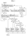
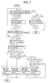
- step 1 when the control according to the flowchart is started by an ignition switch of the vehicle not shown in the figure being closed, in step 1 it is judged if the vehicle operating condition is in a state to allow an execution of a heater failure detecting operation as described hereinbelow. Conditions for such a state may be determined to include that the engine of the vehicle is being started in a cold state, the vehicle is still at a standstill, and the accelerator pedal is not depressed by the driver.
- condition that the parking brake is still actuated may be added.
- these conditions may differ according to the speed and the precision of the detecting operation of the air/fuel ratio sensor or the crankshaft rotational speed sensor, so that when the speed or precision of detecting operation of these sensors is improved, the conditions for the state of executing the failure detection are loosened such that, for example, the failure detection may be carried out after the warming up of the engine, or ultimately, no operating conditions of the engine for the execution of the failure detection are regarded.
- step 2 When the answer of step 1 is yes, the control proceeds to step 2, wherein it is judged if a flag F2 is 1 or not.
- the flag F2 is set to 1 in the below-mentioned step 6. Therefore, as a flag like this is generally reset to 0 at the beginning of the control, when the control comes to this step at first time, the answer is no, and the control proceeds to step 3.
- step 3 fuel heaters for all cylinders are put on. Although these heaters may be controlled according to a feedback of an output signal of the exhaust air/fuel ratio sensor in the normal operation, it is desirable that the operation of the heaters for the failure detection made by step 3 is such an operation as to provide a constant degree of heating to the fuel without a feedback.
- step 4 a control proceeds to step 4, wherein a flag F1 is set to 1.
- step 1 it is judged if the conditions for executing the heater failure detecting operation are still standing.
- step 2 the answer is now yes, and therefore the control proceeds to step 7.
- steps 2 and 6 may be omitted, so that when step 5 was finished, the control proceeds to step 7 without again confirming if the conditions for executing the heater failure detecting operation are standing.
- step 7 the heaters for all cylinders are once put off. Then the control proceeds to step 8, wherein, a mean value Ro of the exhaust air/fuel ratios of all cylinders is detected. Since no heaters for any cylinders are now put on, there should be no difference of the exhaust air/fuel ratio with respect to any cylinder regardless of failure or not failure of the heaters, so that the exhaust air/fuel ratio of each cylinder in the engine operation with no heater being put on is a single mean value.
- step 9 it is judged if the difference between the exhaust air/fuel ratio Ro at non heater operation and the air/fuel ratio R1 for cylinder 1 with the heater being put on is larger than a predetermined threshold value ⁇ Ra.
- the exhaust air/fuel ratio Ro at non heater operation should increase temporarily by a part of the injected fuel sticking to the wall surface of the intake port and/or the combustion chamber.
- step 9 the control proceeds to step 10, wherein it is indicated that the heater for cylinder 1 has failed.
- the control is terminated here by holding an appropriate failure indication.
- step 9 When there is no failure in the heater for cylinder 1, so that the answer of step 9 is yes, the control proceeds to step 11, wherein it is judged if the difference between Ro and R2 for cylinder 2 is larger than the threshold value ⁇ Ra. Similarly, when the answer is no, it is guessed that the heater for cylinder 2 has failed. Then the control proceeds to step 12, wherein it is indicated that the heater for cylinder 2 has failed, and then the control is terminated.
- step 11 When there is no failure in the heater for cylinder 2, so that the answer of step 11 is yes, the control proceeds to step 13, wherein it is judged if the difference between Ro and R3 for cylinder 3 is larger than the threshold value ⁇ Ra. Similarly, when the answer is no, it is guessed that the heater for cylinder 3 has failed. Therefore the control proceeds to step 14, wherein it is indicated that the heater for cylinder 3 has failed, and then the control is terminated.
- step 13 When there is no failure in the heater for cylinder 3, so that the answer of step 13 is yes, the control proceeds to step 15, wherein it is judged if the difference between Ro and R4 for cylinder 4 is larger than the threshold value ⁇ Ra. Similarly, when the answer is no, it is guessed that the heater for cylinder 4 has failed. Then the control proceeds to step 16, wherein it is indicated that the heater for cylinder 4 has failed, and the control is terminated. When there is no failure in the heater for cylinder 4, so that the answer of step 15 is yes, the control is terminated with no further action.
- step 1 When the conditions for executing the heater failure detecting operation are not standing, so that the answer of step 1 is no from the beginning or when the answer of step 1 has turned to no when the control returned to step 1 after having passed through steps 2-6 by a change of the vehicle operating condition in the meantime, so that the conditions for executing the failure detecting operation are no longer standing, the control proceeds from step 2 to step 17, wherein it is judged if the flag F1 is 1 or not.
- step 17 When the control has reached step 17 after having passed through steps 2-6, the flag F1 is 1, so that the answer is yes. In this case, the control proceeds to step 18, wherein the operation of the heaters started in step 3 for the execution of the heater failure detection is stopped, and then in step 19 the flags F1 and F2 are reset to zero, before terminating the control.
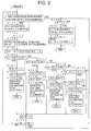
- Fig. 2 is a flowchart showing another embodiment of the heater failure detecting method according to the present invention.
- step 101 When the control is started by a closure of an ignition switch not shown in the figure as in Fig. 1, in step 101, as in step 1 of Fig. 1, it is judged if the conditions for executing the heater failure detecting operation are standing or not. When the answer is yes, the control proceeds to step 102, wherein the heaters for all cylinders are put on for the heater failure detection. This operation may be the same as in step 3. Then the control proceeds to step 103, where a flag F is set to 1.
- step 105 a mean value Rm of R1, R2, R3 and R4 is calculated.
- the mean value Rm expresses a mean air/fuel ratio of the engine operating with the heaters for all cylinders being put on, at, for example, a stoichiometric air/fuel ratio.
- step 106 it is judged if the difference between the air/fuel ratio R1 of the exhaust gas corresponding to cylinder 1 and the meant value Rm is larger than a predetermined threshold value ⁇ Rb or not. If the answer is yes, it is guessed that the heater for cylinder 1 has failed.
- step 107 a count number N1 of a counter constructed as a software by a part of the microcomputer of the vehicle operation control means not shown is increased by 1 starting from the initially reset zero. Then the control proceeds to step 108, wherein it is judge if the count number N1 has exceeded a predetermined threshold value N10 such as e.g. 3-5.
- a predetermined threshold value N10 such as e.g. 3-5.
- step 109 When the answer is yes, the control proceeds to step 109, wherein it is indicated that the heater for cylinder 1 has failed. Then the control is terminated.
- step 110 When the answer of step 108 is no, the control proceeds to step 110, wherein count number N of an overall counter provided also as a software in the microcomputer is increased by 1 starting from the initially reset zero. Then the control proceeds to step 111, wherein it is judged if N has exceeded a threshold value N100 which may be set as e.g. 8-10.
- step 111 When the answer of step 111 is no, the control returns to step 101, and again it is judged if the conditions for executing the heater failure detection are still standing.
- the control passes again through steps 102 and 103 to step 104, wherein the air/fuel ratios Rn of the exhaust gases corresponding to the respective cylinders n are detected.
- step 105 the means value Rm is calculated, and then in step 106 it is judged if the difference between R1 and Rm is larger than ⁇ Rb or not.
- step 107 the count number N1 is further increased by 1.
- step 112 When the answer of step 106 at the first arrival of the control thereto is no, or the answer of step 106 has turned into no after the control through steps 101-108, 110 and 111 has been passed once or several times less than N10, the control proceeds to step 112, wherein it is judged if the difference between the air/fuel ratio R2 of the exhaust gas corresponding to cylinder 2 and the mean value Rm is larger than ⁇ Rb.
- step 113 the control proceeds to step 113, and count number N2 of another counter provided as a software in the microcomputer is increased by 1, starting from the initially reset zero. Then in step 114 it is judged if N2 has exceeded a threshold value N20 which may also be a number such as 3-5. In this case also, when the answer of step 114 becomes yes, the control proceeds to step 115, wherein it is indicated that the heater for cylinder 2 has failed, and then the control is terminated.
- step 114 When the answer of step 114 is no, the control proceeds toward steps 110 and 111, so as further to increase the count value N in addition to the count of the answer of step 108 with regard to cylinder 1 having been yes. As long as the overall count number N does not yet exceed the threshold value N100, the control returns to 101, and upon the confirmation of the conditions for executing the heater failure detection still standing, the detecting control according to step 102 and others is repeated.
- step 106 When the answer of step 106 is no, and the answer of step 112 is also no, the control proceeds to step 116, wherein it is judged if the difference between the air/fuel ratio R3 of the exhaust gas corresponding to cylinder 3 and the mean air/fuel ratio Rm is larger than ARb.
- step 116 When the answer is yes, by employing count number N3 of still another software counter and its threshold value N30, in steps 117 and 118 it is detected for several times that the answer of step 116 is yes, before it is indicated in step 119 that the heater for cylinder 3 has failed, in the same manner as described above with reference to cylinders 1 and 2.
- step 120 When there is no failure in the heaters for cylinders 1, 2 and 3, so that the control reaches step 120, it is judged if R4 for the heater for cylinder 4 is larger than Rm beyond ⁇ Rb. Then by employing count number N4 of still another software counter and its threshold value N40, it is detected for several times in steps 121 and 122 if it is so, before it is indicated in step 123 that the heater for cylinder has failed, in the same manner as described with reference to cylinders 1-3.
- step 106-107 When the operating condition of the engine is unstable, even when, for example, the heater for cylinder 1 has failed, the control will not repeat to proceed from step 106-107 in succession, so that the control proceeds from step 106 to step 112 before the count number N1 exceeds N10, then proceeding to step 116 and further to step 120. Even when it occurs, when the detection cycle is repeated while the conditions for executing the heater failure detection are standing, the count number N1 will soon exceed the threshold value N10, so that the failed heater is definitely detected in spite of some noises.
- step 106 when it is sporadically judged yes in step 106, 112, 116 or 120 due to an unstable operation of the engine in spite of no failure of the heaters, the overall count value N will exceed the threshold value N100 before none of the count values N1, N2, N3 and N4 exceeds its corresponding threshold value N10, N20, N30 or N40. Then the control proceeds to step 124, wherein, since the flag F is 1 at this time, the control proceeds to step 125, and the operation of all heaters started in step 102 for the heater failure detection (non feedback operation) is stopped, and then in step 126 the count values N, N1-N4, and the flag F are reset, and then the control is terminated.
- step 101 When it is judged in step 101 that the conditions for executing the heater failure detection are not standing from the very beginning or such conditions are lost after the control has once proceeded toward step 102 and further to return to step 101 through step 111, the control proceeds to step 124. In this case also, according to whether the control has once proceeded through step 103 or not, the control proceeds through steps 125 and 126 or bypasses these steps, before the control is terminated.
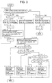
- Fig. 3 is a flowchart showing still another embodiment of the heater failure detecting method according to the present invention.
- the crankshaft rotation angular speed may be obtained by differentiating an output of any sensitive crankshaft rotation sensor on time basis by the microcomputer of the vehicle operation control device.
- the manner of detecting the heater failure according to the flowchart of Fig. 3 is the same as in the flowchart of Fig. 1.
- the steps corresponding to those in the flowchart of Fig. 1 are numbered to correspond to those of Fig. 1 with a conversion into the order of 200.
- the detection of a failure of any one of the heaters can be carried out by employing the crankshaft rotation angular speed as a parameter in the same manner as in Fig. 1 employing the air/fuel ratio of the exhaust gas of the respective cylinders.
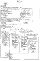
- Fig. 4 is a flowchart showing still another embodiment in which the crankshaft rotation angular speed is employed as the parameter for the heater failure detection control, while the process for the heater failure detection control is proceeded in the same manner as in the embodiment shown in Fig. 2.
- Fig. 5 is a diagram showing an example of a manner for shifting in time the operation of the heaters for respective cylinders of a multi-cylinder internal combustion engine in order to detect the difference exhibited in an operation parameter of the engine such as the exhaust air/furl ratio or the crankshaft rotation angular speed by the engine being operated with the heaters put on in contrast to the engine being operated with the heaters put off.
- an operation parameter of the engine such as the exhaust air/furl ratio or the crankshaft rotation angular speed
- the time points for starting the respective heaters are successively shifted in order to more clearly see the influence of the on and off of the heaters on the operation parameter in regard to the respective cylinders.
- This example also shows how to shift the time points for stopping the operation of the heaters for the respective cylinders.
- the heaters for the respective cylinders are more clearly detected independently of the other with regard to if there is any failure in each of the heaters.
- Fig. 6 is a diagram similar to Fig. 5, showing another embodiment of the manner of shifting in time the operation of the heaters for the respective cylinders of a multi-cylinder internal combustion engine for the same purpose as in Fig. 5.
- two cylinders most remote from one another in the phases of operation of the engine (1st and 4th cylinders or 3rd and 2nd cylinders in a four cylinder engine) are made a pair and the heaters for each pair of cylinders are operated at the same time as shifted in the time of operation relative to the other pair of cylinders.
- Fig. 7 is a flowchart showing an embodiment in which the concept of successively shifting in time the operation of the heaters for the respective cylinders shown in Fig. 5 was incorporated into the embodiment of Fig. 1. In this embodiment, the timing is shifted with respect to putting on the heaters from the put off condition.
- the control is started, in step 401, it is judged if the conditions for executing the heater failure detection are standing.
- step 402 n specifying the cylinders is increased by 1 starting from the initially reset 0.
- n indicates the order of the cylinders to be put on successively with a time shift such as shown in Fig. 5, not to specify the constructional order of the cylinders in the engine.
- step 403 the heater for cylinder n, i.e., 1st cylinder is put on.
- step 404 a flag F is set to 1 to show that the operation of the heaters has started.
- step 405 the exhaust air/fuel ratio R1 corresponding to cylinder 1 is detected.
- step 406 assuming that the engine is a four cylinder engine, it is judged if n has reached 4. When the answer is no, the control returns to step 401, and in this embodiment, after having confirmed that the conditions for executing the heater failure detection are still standing, the control proceeds again to step 402, wherein n is increased by 1. Then in step 403, the heater for cylinder 2 is put on.
- the air/fuel ratios R1-R4 for the four cylinders are detected.
- the air/fuel ratios R1-R4 are each more specifically detected than in the embodiment of Fig. 1 in which all heaters are simultaneously put on, so that a failure or not of each heater is more clearly detected.
- the control proceeds to step 407, wherein all heaters are put off.
- step 408 a mean value Ro of the exhaust air/fuel ratio for the condition that the heaters are not operated is detected.
- the heater failure detection control is carried out in the same manner as in the embodiment of Fig. 1, by setting appropriate threshold values ⁇ Rc1- ⁇ Rc4 for the differences between Ro and R1-R4, respectively.
- R1-R4 are the air/fuel ratios corresponding to cylinders 1-4 with each corresponding heater being individually put on
- individual threshold values such as ⁇ Rc1- ⁇ Rc4 are set out for the differences between Ro and R1-R4, respectively.
- steps corresponding to steps 9-19 in the embodiment of Fig. 1 are numbered as 409-419, respectively, with a conversion of numbers to the order of 400. Since the control of these steps by the flowchart of Fig. 7 should be obvious in view of Fig. 1, further descriptions will be omitted in order to avoid a redundancy of the specification.
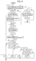
- Fig. 8 is a flowchart modified from the embodiment of Fig. 1 by incorporating the concept of successively shifting in time the operation of the heaters for the respective cylinders as shown in Fig. 5, like the embodiment of Fig. 7, though in this case the times of putting off the heaters are successively shifted for the respective cylinders.
- step 501 it is judged if the conditions for executing the heater failure detection are standing, and when the answer is yes, the control proceeds to step 501a, wherein it is judged if a flag f is 1. In the first cycle, it is 0 as initially reset, and then the control proceeds to step 502, wherein the heaters for all cylinders are put on. Then in step 503, a flag F is set to 1 to show that the heaters are put on.
- Figs. 9 and 10 show an embodiment in which the heater failure detection processes shown in Figs. 7 and 8 are executed in combination, so that when one of the heaters has failed, the failure is more definitely detected. Further, in this combination, it is so arranged that the heaters are successively put on, and after all heaters have been put on, in succession thereto, the heaters are successively put off, thereby sparing the step of putting off all heaters in Fig. 7 (step 407) and the step of putting on all heaters in Fig. 8 (step 502), respectively.
- steps 407 and 408 of Fig. 7 are however moved to between steps 401 and 402 as step 407a and 408a, with a one time pass system by steps 401a and 408b with a flag f1, so that the mean exhaust air/fuel ratio Ro with all heaters being off is detected before successively putting on the heaters.
- step 403 for putting on the heaters is placed as at an earlier stage as possible, so that even during the heater failure detecting operation, the effect of the heaters is obtained as much as possible.
- Rn exhaust air/fuel ratios
- step 410a 412a, 414a or 416a corresponding to steps 410, 412, 414 or 416, respectively
- flag G1, G2, G3 or G4 is set to 1, respectively.
- step 502 is no longer required as the heaters are all already put on.
- step 509, 511, 513 or 515 the control proceeds to steps 509a, 511a, 513a or 515a,respectively, wherein it is judged if the flags G1, G2, G3 or G4 is 1.
- step 510, 512, 514 or 516 it is indicated that the heater of a corresponding cylinder has failed.
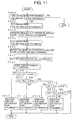
- Fig. 11 is a flowchart showing an embodiment in which the concept of pairing two cylinders most distant from one another in the operational phases of the engine and operating the pairs of heaters with a time shift therebetween shown in Fig. 6 being incorporated into the embodiment of Fig. 1.
- the time point of putting on of the pairs of heaters are shifted between the pairs.
- step 604 the control proceeds to step 604, wherein the heaters for the third and second cylinders are put on. Then in step 605, the exhaust air/furl ratios R3 and R2 corresponding to the third and second cylinders are detected. Then in step 607, all heaters are put off, and in step 608, a means exhaust air/fuel ratio Ro for the engine operating with all heaters being put off is detected.
- step 601 Based upon the exhaust air/fuel ratios R1-R4 corresponding to the first-fourth cylinders with the heaters being put on and the mean exhaust air/fuel ratio Ro with the heaters not being put on, it is detected if any of the heaters has failed according to step 609-616 corresponding respectively to steps 9-16 in Fig. 1. On the other hand, when the answer of step 601 is no, the control is immediately terminated.
- the control operations of this embodiment will be clear in view of the descriptions made for the embodiment of Fig. 1. Therefore, further descriptions will be omitted in order to avoid a redundancy of the description.
- Fig. 12 shows an embodiment in which the concept of pairing two cylinders most distant from one another in the operational phases thereof and operating the pairs of heaters with a time shift therebetween shown in Fig. 6 is incorporated into the embodiment of Fig. 1 as in the embodiment of Fig. 11, though in this embodiment the shifting of operation between the pairs of cylinders is made with respect to putting off the heaters from the put on condition.
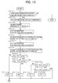
- Figs. 13 and 14 as combined at terminal B show an embodiment in which a failure of any heater is more definitely detected by the heater failure detecting processes of Figs. 11 and 12 being executed in combination. Further, in this combination, it is so arranged that the heaters are put on by pairs, and after all the heaters have been put on, in succession thereto, the heaters are put off by pairs.
- steps 607 and 608 of Fig. 11 are moved to between steps 601 and 602 as steps 607a and 608a, so that the mean exhaust air/fuel ratio Ro with all heaters put off is first detected before the heaters are put on by pairs. Thereafter, steps 602 through 605 and steps 609, 611, 613 and 615 are executed in the same manner as in Fig. 11.
- the control proceeds to step 610a, 612a, 614a or 616a, and flag H1, H2, H3 or H4 is set to 1.
- step 709, 711, 713 or 715 the control proceeds to step 709a, 711a, 713a or 715a, and it is judged if the flag H1, H2, H3 or H4 is 1. Then by a double checking according to the processes of Figs. 12 and 13, a failure of any heater is detected.
- a failure of the fuel heaters of a multi-cylinder internal combustion engine of vehicles by utilizing a microcomputer of a vehicle operation control device and sensors already provided in the vehicle such as an air/fuel ratio sensor or a crankshaft rotation sensor, with a supplement of substantially only a software, a failure of the heater corresponding to one of the cylinders is detected based upon a change exhibited in at least one parameter with regard to the operating conditions of the engine such as exhaust air/fuel ratio, crankshaft rotation angular speed, etc. by the injected fuel not having been heated as expected by a predetermined operation of each heater.
Landscapes
- Engineering & Computer Science (AREA)
- Chemical & Material Sciences (AREA)
- Combustion & Propulsion (AREA)
- Mechanical Engineering (AREA)
- General Engineering & Computer Science (AREA)
- Combined Controls Of Internal Combustion Engines (AREA)
- Electrical Control Of Air Or Fuel Supplied To Internal-Combustion Engine (AREA)
Abstract
Description
Claims (11)
- A method for detecting a failure of heaters provided in a fuel supply system of an internal combustion engine for heating an injection fuel, comprising the step of detecting the failure based upon a change which occurs at least in a parameter concerned with operating conditions of the engine due to the injected fuel not having been heated to a predetermined degree of heating.
- A method according to claim 1, wherein the change in the parameter is an increase of exhaust air/fuel ratio of an exhaust gas of the engine as compared with a value thereof to be expected when the injected fuel has been heated to the predetermined degree of heating.
- A method according to claim 1, wherein the change in the parameter is a change in a performance of at least one of rotational speed, rotational acceleration and changes thereof of the engine corresponding to one of cylinders thereof.
- A method according to claim 1, 2 or 3, wherein the change in the parameter is a substantial non difference between values of the parameter according to operations of the engine with the heater being put on and the heater not being put on, respectively.
- A method according to claim 1, 2 or 3, wherein the change in the parameter is a substantial difference in values thereof between cylinders of the engine.
- A method according to claim 4, wherein the heaters for respective cylinders of the engine are operated with a time shift therebetween in order to detect the difference in the parameter between an operation of the engine with the heaters being put on and an operation of the engine with the heaters not being put on.
- A method according to claim 6, wherein the heaters for respective cylinders are put on with a time shift therebetween for the time shifted operations of the heaters for the respective cylinders.
- A method according to claim 6 or 7, wherein the heaters for respective cylinders are put off with a time shift therebetween for the time shifted operations of the heaters for the respective cylinders.
- A method according to claim 4, wherein two cylinders which are most distant from one another in phases of operation of the engine are made a pair of cylinders, and the heaters for such pairs of cylinders are operated with a time shift therebetween in order to detect a difference in the parameter between an operation of the engine with the heaters being operated and an operation of the engine with the heaters not being operated.
- A method according to claim 9, wherein the time shifted operations for the respective cylinders are to put on the heaters with a time shift between respective such pairs of cylinders.
- A method according to claim 9 or 10, wherein the time shifted operations of the heaters are to put off the heaters with a time shift between respective such pairs cylinders.
Applications Claiming Priority (4)
| Application Number | Priority Date | Filing Date | Title |
|---|---|---|---|
| JP2001063586 | 2001-03-07 | ||
| JP2001063586 | 2001-03-07 | ||
| JP2001347176 | 2001-11-13 | ||
| JP2001347176 | 2001-11-13 |
Publications (3)
| Publication Number | Publication Date |
|---|---|
| EP1239134A2 true EP1239134A2 (en) | 2002-09-11 |
| EP1239134A3 EP1239134A3 (en) | 2004-05-19 |
| EP1239134B1 EP1239134B1 (en) | 2005-04-13 |
Family
ID=26610785
Family Applications (1)
| Application Number | Title | Priority Date | Filing Date |
|---|---|---|---|
| EP02002766A Expired - Lifetime EP1239134B1 (en) | 2001-03-07 | 2002-02-07 | Method for detecting failure of injection fuel heaters of internal combustion engine |
Country Status (3)
| Country | Link |
|---|---|
| US (1) | US6792929B2 (en) |
| EP (1) | EP1239134B1 (en) |
| DE (1) | DE60203659T2 (en) |
Cited By (1)
| Publication number | Priority date | Publication date | Assignee | Title |
|---|---|---|---|---|
| WO2004092558A3 (en) * | 2003-04-10 | 2004-12-16 | Chrysalis Tech Inc | Capillary heating control and fault detection system and methodology for fuel system in an internal combustion engine |
Families Citing this family (2)
| Publication number | Priority date | Publication date | Assignee | Title |
|---|---|---|---|---|
| CN104819738B (en) * | 2015-04-21 | 2017-06-16 | 嘉兴海格力思电子科技有限公司 | The method that sensor construction loosens detection |
| DE102016224427B3 (en) | 2016-12-08 | 2018-04-05 | Continental Automotive Gmbh | Method and device for operating an internal combustion engine working with alcohol and alcohol mixed fuels |
Family Cites Families (11)
| Publication number | Priority date | Publication date | Assignee | Title |
|---|---|---|---|---|
| JPS54109535A (en) * | 1978-02-17 | 1979-08-28 | Toyota Motor Corp | Engine of automobile |
| JPS57152446U (en) * | 1981-03-23 | 1982-09-24 | ||
| JP3166538B2 (en) | 1995-03-14 | 2001-05-14 | トヨタ自動車株式会社 | Failure diagnosis device for fuel supply system |
| JP3275672B2 (en) * | 1995-12-06 | 2002-04-15 | トヨタ自動車株式会社 | Air-fuel ratio sensor heater control device |
| JPH09291873A (en) | 1996-04-30 | 1997-11-11 | Denso Corp | Glow plug energization control device |
| US5894832A (en) | 1996-07-12 | 1999-04-20 | Hitachi America, Ltd., Research And Development Division | Cold start engine control apparatus and method |
| JPH10238424A (en) | 1997-02-21 | 1998-09-08 | Denso Corp | Fuel injection device |
| JP3891234B2 (en) * | 1997-10-02 | 2007-03-14 | 株式会社デンソー | Air-fuel ratio sensor system abnormality diagnosis device for internal combustion engine |
| US6176226B1 (en) | 1998-11-16 | 2001-01-23 | Siemens Automotive Corporation | Control method and apparatus for a heated tip injector |
| DE19908352A1 (en) | 1999-02-26 | 2000-08-31 | Bosch Gmbh Robert | Fuel injection method for an internal combustion engine |
| US6226976B1 (en) | 1999-02-26 | 2001-05-08 | Alliedsignal, Inc. | Variable fuel heating value adaptive control for gas turbine engines |
-
2002
- 2002-01-18 US US10/050,798 patent/US6792929B2/en not_active Expired - Fee Related
- 2002-02-07 DE DE60203659T patent/DE60203659T2/en not_active Expired - Lifetime
- 2002-02-07 EP EP02002766A patent/EP1239134B1/en not_active Expired - Lifetime
Cited By (2)
| Publication number | Priority date | Publication date | Assignee | Title |
|---|---|---|---|---|
| US7032576B2 (en) | 2002-05-10 | 2006-04-25 | Philip Morris Usa Inc. | Capillary heating control and fault detection system and methodology for fuel system in an internal combustion engine |
| WO2004092558A3 (en) * | 2003-04-10 | 2004-12-16 | Chrysalis Tech Inc | Capillary heating control and fault detection system and methodology for fuel system in an internal combustion engine |
Also Published As
| Publication number | Publication date |
|---|---|
| US6792929B2 (en) | 2004-09-21 |
| DE60203659T2 (en) | 2006-03-02 |
| DE60203659D1 (en) | 2005-05-19 |
| US20020124839A1 (en) | 2002-09-12 |
| EP1239134A3 (en) | 2004-05-19 |
| EP1239134B1 (en) | 2005-04-13 |
Similar Documents
| Publication | Publication Date | Title |
|---|---|---|
| CN101535614B (en) | Method of controlling internal combustion engine | |
| US7387011B2 (en) | Deterioration diagnosis system for exhaust gas sensor | |
| EP2151567B1 (en) | Cetane number estimating device and method | |
| US5881552A (en) | Control system for internal combustion engines and control system for vehicles | |
| US6305344B1 (en) | Method and apparatus for controlling fuel to an engine during coolant failure | |
| CN101476510A (en) | Temperature sensor diagnostics | |
| US8127744B2 (en) | Cold start engine control diagnostic systems and methods | |
| JP2010025090A (en) | Abnormality diagnosing device for air-fuel ratio sensor | |
| JPH0823333B2 (en) | Ignition timing control device for internal combustion engine | |
| CN103590958B (en) | Method for controlling an ignition system of an internal combustion engine and an ignition system | |
| US4967727A (en) | Fuel controller for an internal combustion engine | |
| EP1239134B1 (en) | Method for detecting failure of injection fuel heaters of internal combustion engine | |
| US7448360B2 (en) | Controller of internal combustion engine | |
| KR20140097562A (en) | Method for learning a minimum actuation duration of injection valves of an internal combustion engine | |
| JP2004132314A (en) | Control device for internal combustion engine | |
| EP1167730A1 (en) | Device for controlling rotational speed of internal combustion engine | |
| US6874359B2 (en) | Control apparatus and control method of engine | |
| GB2447387A (en) | Combustion state judging method for internal combustion engine | |
| JP3933954B2 (en) | Failure detection method for an injected fuel heating device of an internal combustion engine | |
| JP3162297B2 (en) | Cylinder determination control device for internal combustion engine | |
| JP6160035B2 (en) | Cylinder air-fuel ratio variation abnormality detecting device for multi-cylinder internal combustion engine | |
| JPS59101577A (en) | Controller for internal-combustion engine | |
| JP2692106B2 (en) | Abnormality diagnosis device for fuel pressure control system | |
| JP4172870B2 (en) | Multi-cylinder engine misfire control system | |
| JP2007192081A (en) | Control device for internal combustion engine |
Legal Events
| Date | Code | Title | Description |
|---|---|---|---|
| PUAI | Public reference made under article 153(3) epc to a published international application that has entered the european phase |
Free format text: ORIGINAL CODE: 0009012 |
|
| AK | Designated contracting states |
Kind code of ref document: A2 Designated state(s): AT BE CH CY DE DK ES FI FR GB GR IE IT LI LU MC NL PT SE TR |
|
| AX | Request for extension of the european patent |
Free format text: AL;LT;LV;MK;RO;SI |
|
| PUAL | Search report despatched |
Free format text: ORIGINAL CODE: 0009013 |
|
| AK | Designated contracting states |
Kind code of ref document: A3 Designated state(s): AT BE CH CY DE DK ES FI FR GB GR IE IT LI LU MC NL PT SE TR |
|
| AX | Request for extension of the european patent |
Extension state: AL LT LV MK RO SI |
|
| RIC1 | Information provided on ipc code assigned before grant |
Ipc: 7F 02D 41/22 A Ipc: 7F 02M 53/02 B Ipc: 7F 02M 31/00 B |
|
| 17P | Request for examination filed |
Effective date: 20040504 |
|
| GRAP | Despatch of communication of intention to grant a patent |
Free format text: ORIGINAL CODE: EPIDOSNIGR1 |
|
| GRAS | Grant fee paid |
Free format text: ORIGINAL CODE: EPIDOSNIGR3 |
|
| AKX | Designation fees paid |
Designated state(s): DE FR GB |
|
| GRAA | (expected) grant |
Free format text: ORIGINAL CODE: 0009210 |
|
| AK | Designated contracting states |
Kind code of ref document: B1 Designated state(s): DE FR GB |
|
| REG | Reference to a national code |
Ref country code: GB Ref legal event code: FG4D |
|
| REG | Reference to a national code |
Ref country code: IE Ref legal event code: FG4D |
|
| REF | Corresponds to: |
Ref document number: 60203659 Country of ref document: DE Date of ref document: 20050519 Kind code of ref document: P |
|
| ET | Fr: translation filed | ||
| PLBE | No opposition filed within time limit |
Free format text: ORIGINAL CODE: 0009261 |
|
| STAA | Information on the status of an ep patent application or granted ep patent |
Free format text: STATUS: NO OPPOSITION FILED WITHIN TIME LIMIT |
|
| 26N | No opposition filed |
Effective date: 20060116 |
|
| REG | Reference to a national code |
Ref country code: GB Ref legal event code: 746 Effective date: 20100430 |
|
| PGFP | Annual fee paid to national office [announced via postgrant information from national office to epo] |
Ref country code: DE Payment date: 20130131 Year of fee payment: 12 Ref country code: GB Payment date: 20130207 Year of fee payment: 12 Ref country code: FR Payment date: 20130301 Year of fee payment: 12 |
|
| REG | Reference to a national code |
Ref country code: DE Ref legal event code: R119 Ref document number: 60203659 Country of ref document: DE |
|
| GBPC | Gb: european patent ceased through non-payment of renewal fee |
Effective date: 20140207 |
|
| REG | Reference to a national code |
Ref country code: FR Ref legal event code: ST Effective date: 20141031 |
|
| REG | Reference to a national code |
Ref country code: DE Ref legal event code: R119 Ref document number: 60203659 Country of ref document: DE Effective date: 20140902 |
|
| PG25 | Lapsed in a contracting state [announced via postgrant information from national office to epo] |
Ref country code: FR Free format text: LAPSE BECAUSE OF NON-PAYMENT OF DUE FEES Effective date: 20140228 Ref country code: DE Free format text: LAPSE BECAUSE OF NON-PAYMENT OF DUE FEES Effective date: 20140902 Ref country code: GB Free format text: LAPSE BECAUSE OF NON-PAYMENT OF DUE FEES Effective date: 20140207 |