EP1239116A2 - Fluted blisk - Google Patents
Fluted blisk Download PDFInfo
- Publication number
- EP1239116A2 EP1239116A2 EP02251636A EP02251636A EP1239116A2 EP 1239116 A2 EP1239116 A2 EP 1239116A2 EP 02251636 A EP02251636 A EP 02251636A EP 02251636 A EP02251636 A EP 02251636A EP 1239116 A2 EP1239116 A2 EP 1239116A2
- Authority
- EP
- European Patent Office
- Prior art keywords
- blades
- blisk
- fluted
- rim
- weld
- Prior art date
- Legal status (The legal status is an assumption and is not a legal conclusion. Google has not performed a legal analysis and makes no representation as to the accuracy of the status listed.)
- Granted
Links
Images


Classifications
-
- F—MECHANICAL ENGINEERING; LIGHTING; HEATING; WEAPONS; BLASTING
- F01—MACHINES OR ENGINES IN GENERAL; ENGINE PLANTS IN GENERAL; STEAM ENGINES
- F01D—NON-POSITIVE DISPLACEMENT MACHINES OR ENGINES, e.g. STEAM TURBINES
- F01D5/00—Blades; Blade-carrying members; Heating, heat-insulating, cooling or antivibration means on the blades or the members
- F01D5/02—Blade-carrying members, e.g. rotors
-
- F—MECHANICAL ENGINEERING; LIGHTING; HEATING; WEAPONS; BLASTING
- F01—MACHINES OR ENGINES IN GENERAL; ENGINE PLANTS IN GENERAL; STEAM ENGINES
- F01D—NON-POSITIVE DISPLACEMENT MACHINES OR ENGINES, e.g. STEAM TURBINES
- F01D5/00—Blades; Blade-carrying members; Heating, heat-insulating, cooling or antivibration means on the blades or the members
- F01D5/34—Rotor-blade aggregates of unitary construction, e.g. formed of sheet laminae
-
- B—PERFORMING OPERATIONS; TRANSPORTING
- B23—MACHINE TOOLS; METAL-WORKING NOT OTHERWISE PROVIDED FOR
- B23K—SOLDERING OR UNSOLDERING; WELDING; CLADDING OR PLATING BY SOLDERING OR WELDING; CUTTING BY APPLYING HEAT LOCALLY, e.g. FLAME CUTTING; WORKING BY LASER BEAM
- B23K20/00—Non-electric welding by applying impact or other pressure, with or without the application of heat, e.g. cladding or plating
- B23K20/12—Non-electric welding by applying impact or other pressure, with or without the application of heat, e.g. cladding or plating the heat being generated by friction; Friction welding
- B23K20/129—Non-electric welding by applying impact or other pressure, with or without the application of heat, e.g. cladding or plating the heat being generated by friction; Friction welding specially adapted for particular articles or workpieces
-
- F—MECHANICAL ENGINEERING; LIGHTING; HEATING; WEAPONS; BLASTING
- F01—MACHINES OR ENGINES IN GENERAL; ENGINE PLANTS IN GENERAL; STEAM ENGINES
- F01D—NON-POSITIVE DISPLACEMENT MACHINES OR ENGINES, e.g. STEAM TURBINES
- F01D5/00—Blades; Blade-carrying members; Heating, heat-insulating, cooling or antivibration means on the blades or the members
- F01D5/12—Blades
- F01D5/14—Form or construction
- F01D5/141—Shape, i.e. outer, aerodynamic form
- F01D5/142—Shape, i.e. outer, aerodynamic form of the blades of successive rotor or stator blade-rows
- F01D5/143—Contour of the outer or inner working fluid flow path wall, i.e. shroud or hub contour
-
- B—PERFORMING OPERATIONS; TRANSPORTING
- B23—MACHINE TOOLS; METAL-WORKING NOT OTHERWISE PROVIDED FOR
- B23K—SOLDERING OR UNSOLDERING; WELDING; CLADDING OR PLATING BY SOLDERING OR WELDING; CUTTING BY APPLYING HEAT LOCALLY, e.g. FLAME CUTTING; WORKING BY LASER BEAM
- B23K2101/00—Articles made by soldering, welding or cutting
- B23K2101/001—Turbines
-
- F—MECHANICAL ENGINEERING; LIGHTING; HEATING; WEAPONS; BLASTING
- F05—INDEXING SCHEMES RELATING TO ENGINES OR PUMPS IN VARIOUS SUBCLASSES OF CLASSES F01-F04
- F05D—INDEXING SCHEME FOR ASPECTS RELATING TO NON-POSITIVE-DISPLACEMENT MACHINES OR ENGINES, GAS-TURBINES OR JET-PROPULSION PLANTS
- F05D2230/00—Manufacture
- F05D2230/20—Manufacture essentially without removing material
- F05D2230/23—Manufacture essentially without removing material by permanently joining parts together
-
- Y—GENERAL TAGGING OF NEW TECHNOLOGICAL DEVELOPMENTS; GENERAL TAGGING OF CROSS-SECTIONAL TECHNOLOGIES SPANNING OVER SEVERAL SECTIONS OF THE IPC; TECHNICAL SUBJECTS COVERED BY FORMER USPC CROSS-REFERENCE ART COLLECTIONS [XRACs] AND DIGESTS
- Y10—TECHNICAL SUBJECTS COVERED BY FORMER USPC
- Y10T—TECHNICAL SUBJECTS COVERED BY FORMER US CLASSIFICATION
- Y10T29/00—Metal working
- Y10T29/49—Method of mechanical manufacture
- Y10T29/49316—Impeller making
- Y10T29/49318—Repairing or disassembling
-
- Y—GENERAL TAGGING OF NEW TECHNOLOGICAL DEVELOPMENTS; GENERAL TAGGING OF CROSS-SECTIONAL TECHNOLOGIES SPANNING OVER SEVERAL SECTIONS OF THE IPC; TECHNICAL SUBJECTS COVERED BY FORMER USPC CROSS-REFERENCE ART COLLECTIONS [XRACs] AND DIGESTS
- Y10—TECHNICAL SUBJECTS COVERED BY FORMER USPC
- Y10T—TECHNICAL SUBJECTS COVERED BY FORMER US CLASSIFICATION
- Y10T29/00—Metal working
- Y10T29/49—Method of mechanical manufacture
- Y10T29/49316—Impeller making
- Y10T29/4932—Turbomachine making
- Y10T29/49321—Assembling individual fluid flow interacting members, e.g., blades, vanes, buckets, on rotary support member
-
- Y—GENERAL TAGGING OF NEW TECHNOLOGICAL DEVELOPMENTS; GENERAL TAGGING OF CROSS-SECTIONAL TECHNOLOGIES SPANNING OVER SEVERAL SECTIONS OF THE IPC; TECHNICAL SUBJECTS COVERED BY FORMER USPC CROSS-REFERENCE ART COLLECTIONS [XRACs] AND DIGESTS
- Y10—TECHNICAL SUBJECTS COVERED BY FORMER USPC
- Y10T—TECHNICAL SUBJECTS COVERED BY FORMER US CLASSIFICATION
- Y10T29/00—Metal working
- Y10T29/49—Method of mechanical manufacture
- Y10T29/49316—Impeller making
- Y10T29/4932—Turbomachine making
- Y10T29/49325—Shaping integrally bladed rotor
Landscapes
- Engineering & Computer Science (AREA)
- Mechanical Engineering (AREA)
- General Engineering & Computer Science (AREA)
- Physics & Mathematics (AREA)
- Fluid Mechanics (AREA)
- Ceramic Engineering (AREA)
- Structures Of Non-Positive Displacement Pumps (AREA)
- Pressure Welding/Diffusion-Bonding (AREA)
- Turbine Rotor Nozzle Sealing (AREA)
Abstract
Description
- The present invention relates generally to gas turbine engines, and, more specifically, to blisks therein.
- A gas turbine engine includes various stages of bladed disks in the compressor and turbine thereof which pressurize air in the former and expand hot combustion gases in the latter. The compressor blades or turbine blades are typically mounted to their supporting disks by dovetails which are radially retained in corresponding dovetail slots in the rims of the disks.
- Advantages in performance, manufacture, and weight may be obtained by integrally forming the blades and disks in a unitary or one-piece construction known as a blisk. In one method of manufacture, the individual blades and features of the supporting disk are machined from a common blank of metal. Complex three dimensional machining is required to precisely obtain the required aerodynamic flow passages between the blades.
- Since blisks may be damaged in the normal course of operation in a gas turbine engine before their useful lives have been met, it is desirable to repair the blisks. However, since the blades are integrally formed with the disk, they are not readily individually removable in the manner of bladed disks having dovetails.
- Accordingly, either portions of an individual damaged blade may be removed by machining and replaced with a corresponding blade piece, or the entire damaged blade may be removed and replaced. In either example, the repaired blisk should be returned as close as possible to its original strength for completing its original useful life without undesirable early termination thereof.
- Another form of blisk manufacture and repair uses translational friction welding for integrally welding individual blades to a disk. The disk is typically initially fabricated with a row of integral stubs extending radially outwardly from the rim of the disk. Each stub has a smooth weld surface which complements a corresponding smooth blade root for permitting friction welding therebetween.
- Each blade initially includes a fixturing collar near the blade root so that compression and translation forces may be applied to the individual blade for developing friction at the weld surface as the blade is quickly oscillated during the welding process. The blade and stub material at the weld surface locally fuses to form a friction weld bond thereat, after which the resulting weld flashing and fixturing collar are removed by conventional machining for achieving the desired aerodynamic contour of the blade and rim surfaces.
- Since the friction welding forces are substantial, the original rim stubs are provided oversize with excess material to prevent undesirable plastic deformation of the stubs and blade during friction welding. The excess material may then be removed by machining following the friction welding process.
- However, in the event that repair of the blisk is desired and a complete blade must be removed, the remaining stub no longer includes the original excess material. The correspondingly smaller stub is therefor subject to undesirable deformation during the friction welding process of a replacement blade, which can damage the blisk and render it unusable for return to service in the engine.
- Another problem with friction welding of blisks is the exposure to the environment along the edges of the weld surface as the blade is oscillated during welding. The original oversized stub and correspondingly oversized blade root provide additional surface area for decreasing the likelihood of environmental contamination at the resulting weld line. The excess material machined away after friction welding typically removes therewith any undesirable contamination around the weld surface. Since the stubs no longer have excess material for the repair operation, the weld surfaces are subject to environmental contamination.
- These problems of typical friction welding are further compounded by the axial contour of the disk rim defining the inner flowpath boundary of the flow passages between adjacent blades. In a typical entry-stage configuration of a fan or compressor blisk, the blisk rim increases in diameter between its forward and aft ends, and typically has an arcuate contour therebetween which may have a generally S-shape. Accordingly, the stub weld surface typically follows the axial profile of the disk rim for maintaining the weld surface as large as possible.
- Typical compressor blades have maximum thickness in their midchord regions, with correspondingly thin leading and trailing edges, and typically decrease in thickness from root to tip thereof. The rim stub and the blade root therefore typically have complementary arcuate weld surfaces for maximizing the surface area and reducing distortion during the friction welding process.
- Since the weld plane is arcuate, both the rim stub and blade root require precise three dimensional machining to create closely matching surfaces for achieving complete friction welding. And, the arcuate weld surface can only be translated in the axisymmetric direction circumferentially around the disk rim. This circumferential or lateral frictional oscillation of the blade on its corresponding stub is rendered more difficult when conducted between two adjacent blades already welded to their stubs.
- Accordingly, it is desired to provide a blisk having an improved configuration of the weld plane for advantages in both original manufacturing thereof as well as during subsequent repair.
- According to the present invention, a blisk includes a disk having a rim. A row of blades extends outwardly from the rim in a unitary construction. The blades are spaced apart in the disk rim to define fluted inner flowpath channels extending axially between the blades to bound corresponding flow passages therebetween.
- The invention, in accordance with preferred and exemplary embodiments, together with further objects and advantages thereof, is more particularly described in the following detailed description taken in conjunction with the accompanying drawings in which:
- Figure 1 is an isometric view of a portion of a gas turbine engine compressor blisk and a schematic method of manufacture thereof.
- Figure 2 is a radial sectional view of the blisk illustrated in Figure 1 and schematic representation of translation friction welding thereof.
- Figure 3 is an enlarged elevational view of a portion of the welding joint between the blade and disk illustrated in Figure 2 within the dashed circle labeled 3.
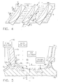
- Figure 4 is a top planiform view of a portion of the blisk illustrated in Figure 2 showing three adjacent blades having corresponding fluted inner flowpath channels extending in width circumferentially therebetween.
- Figure 5 is a radial sectional view of an exemplary fluted flow channel illustrated in Figure 4 and taken along 5-5 near the blade leading edges.
- Figure 6 is radial sectional view of the fluted channel illustrated in Figure 4 and taken along line 6-6 in the blade midchord region.
- Figure 7 is a radial sectional view of the fluted channel illustrated in Figure 4 and taken along line 7-7 near the blade trailing edges.
- Figure 8 is an isometric view, like Figure 7, of the blisk being repaired in accordance with an exemplary embodiment.
-
- Illustrated in Figure 1 is a portion of an
annular blisk 10 which is generally axisymmetrical about a longitudinal oraxial centerline axis 12 thereof. The blisk is configured for use in a gas turbine engine, and is in the exemplary form of a compressor or fan blisk for pressurizingair 14 during operation. - The blisk includes an
annular disk 16 which includes an axiallywide rim 16a, anarrower web 16b, and awider hub 16c in a unitary construction. - A row of
compressor rotor blades 18 extends radially outwardly from therim 16a in a unitary or one-piece construction therewith for defining the completed blisk. As indicated above, the blades are integral with the disk and do not include typical dovetails which would otherwise permit their ready removal or insertion in the form of a conventional bladed-disk. - Each blade may have any conventional aerodynamic configuration for pressurizing the air during operation and defines with its circumferential neighbor a
corresponding flow passage 20 through which theair 14 is channeled during operation. Thedisk rim 16a includes aninner flowpath channel 22 between each of the adjacent blade pairs which extends axially along the blades and between the forward and aft ends of the rim disposed on axially opposite sides thereof. - The
inner channel 22 defines the radially inner boundary of theflow passage 20, and the radially outer boundary of the flow passage is typically defined by a surrounding annular casing orshroud 24 of any conventional configuration. In this way, as the blisk rotates during operation within thestationary shroud 24corresponding flow passages 20 are defined between each blade pair through which the air is channeled for being pressurized or compressed. - Each
blade 18 includes a generallyconvex suction side 26 and a circumferentially opposite generallyconcave pressure side 28 extending axially or chordally between opposite leading andtrailing edges root 34 totip 36. In accordance with the present invention, the innerflow path channels 22 are fluted for providing substantial advantages in manufacture, repair, and aerodynamic performance. - More specifically, conventional blisks have axisymmetric inner flowpaths which are surfaces of revolution around the axial centerline axis. Axisymmetric surfaces are correspondingly convex outwardly and are readily machined during the manufacturing process. In contrast, the
fluted channels 22 are not surfaces of revolution relative to thecenterline axis 12, and are thusly non-axisymmetric, but, instead, are circumferentially arcuate between adjacent blades and join the blades at correspondingarcuate fillets 38. Furthermore, each of thefluted channels 22 is preferably asymmetric circumferentially between adjacent blades relative to the primary axial flow direction of the air along the flutes and between the forward and aft ends of the disk rim. - Each of the
fluted channels 22 has a generally concave profile or contour extending radially inwardly toward thecenterline axis 12, and varies in that contour axially along thebounding blades 18 between the forward and aft ends of the disk rim. Whereas the typical axisymmetric inner flowpath of a blisk is generally convex, the fluted channels are generally concave and opposite thereto. - A particular advantage of the
fluted channels 22 is corresponding improvement over the original manufacture or fabrication of the blisk and repair thereof. More specifically, thedisk rim 16a illustrated in Figures 1 and 2 includes integral or unitaryplanar stubs 40 each having a planar weld surface orflat plane 42 which complements thecorresponding blade root 34, which is also planar or flat. - The stubs and roots are frictionally welded together to form a fused or weld-bonded joint therebetween for integrally joining all the blades to the disk to form the unitary or one-piece construction thereof. The welded blades thus become an integral part of the disk and are not readily removable therefrom without a machining or cutting operation.
- Of particular significance in this blisk construction is the
weld plane 42 being disposed in thefillets 38, instead of being disposed radially outwardly therefrom in thinner sections of the resulting blade or stub. As indicated above, translation friction welding requires substantial friction forces between a blade and rim stub, and if the stubs are too narrow or thin then undesirable deformation of the blade and stub may occur during the process which can adversely affect the final configuration of the welded blade. Weak stubs are prone to distortion, with strong stubs being desired. - Also indicated above is that the stubs and blade roots may be initially made suitably oversize for increasing the strength thereof for undergoing the friction weld process, but such oversize is not available in the stubs for subsequent repair.
- Accordingly, by initially locating the weld planes 42 in the fillets of the
stubs 40, the additional width of the stub at the fillets substantially increases the strength thereof and better withstands the large friction welding forces. - However, locating the weld planes within the stub fillets is not readily accomplished in view of the typical three dimensional configuration of the
disk rim 16a. If the outer surface of the rim were purely cylindrical, then straight stubs with uniformly small fillets could be readily used. - However, the
disk rim 16a illustrated in Figures 1 and 2 is representative of typical compressor blisks in which the rim increases in diameter between its forward and aft ends and is not simply cylindrical. Accordingly, thefluted channels 22 correspondingly diverge radially outwardly between the forward and aft ends of the disk rim and correspondingly increase in radius from the blisk centerline axis. Notwithstanding the variable axially profile of the disk rim, the weld planes 42 remain flat or planar and are suitably tilted to vary in radial distance from both the blisk centerline axis and the correspondingfluted channels 22 extending axially between the opposite ends of the disk rim. - Since the disk rim varies in diameter and contour between its forward and aft ends, a conventional stub would also vary in contour for maintaining a relatively small and constant fillet along the disk rim for maximizing aerodynamic performance of the flow passage while maintaining the desired flow area thereof. However, the variable contour stubs resulting therefrom are undesirable for the several reasons presented above.
- Equally undesirable is the simple introduction of a planar stub generally conforming with the variable contour of the disk rim which would inherently position the weld plane at relatively thin portions of the blade at either its leading or trailing edges or chordally therebetween at locations radially outwardly of the stub fillets. It is undesirable to merely increase the size of the fillets to reach the varying diameter weld plane because those fillets directly affect aerodynamic performance of the blades including the required flow area of the passages.
- Accordingly, by introducing the
fluted channels 22 instead of typical surface-of-revolution flow channels, theweld plane 42 may remain flat over its entire extent between the leading and trailing edges of the blade while being positioned within the correspondingfillets 38 for maintaining structural integrity of the stubs and resistance to friction welding without compromising aerodynamic performance. As shown in Figures 1 and 2, thefluted channels 22 vary in radial depth preferably non-linearly between the forward and aft ends of the disk rim, and theweld plane 42 correspondingly varies in radial position inside thefillets 38 axially between the opposite ends of the rim. - As initially shown in Figure 1, the
fluted channels 22 vary in circumferential profile or contour and have a maximum sectional depth skewed or swerved toward the blade suction sides 26 axially between the forward and aft ends of thedisk rim 16a. This general contour of the fluted channels results from the manner of originally making the blisk to accommodate the contradictory objectives of a planar weld surface inside correspondingly small fillets with a disk rim varying in diameter and axial contour between the forward and aft ends thereof. - More specifically, Figure 1 also illustrates schematically a method of making the
blisk 10 in accordance with a preferred embodiment. Thedisk 16 without the blades is initially fabricated in any conventional manner such as by forging and machining to produce the desiredplanar stubs 40 extending radially outwardly from the disk rim, preferably suitably oversized. - The
individual blades 18 are fabricated in any conventional manner such as by forging and machining as desired. In this way the individual fabrication of the blades permits precise control of the various dimensions thereof without obstruction by any other blade or the disk which typically occurs in the machining in the blisk and blades from a common blank. - Each
blade 18 is preferably fabricated with anintegral fixturing collar 44 disposed closely radially above theplanar root 34 thereof. Translationfriction welding equipment 46 of any conventional configuration is then used for friction welding theplanar root 34 to the correspondingplanar stub 40 for each of the blades by translating and reciprocating thecollar 44 axially or chordally. As shown in general in Figures 1 and 2, and in more detail in Figure 3, the welding equipment produces a radially inwardly directed compression or upset force F through thecollar 44 to create substantial friction forces as thecollar 44 is oscillated under translation force T in rapid motion to locally fuse the blade root to the rim stub to form a weld joint along the weld plane. - As shown in Figures 3 and 4, translation of the
blade 18 during the friction welding process preferably occurs in the chordal direction along the greatest length of thestub 40 as opposed to its substantially narrower circumferential width. In this way, as the blade is oscillated during friction welding as illustrated in Figure 3, only small portions at the opposite leading and trailing edges of the blade at theroots 34 are exposed to the environment for substantially reducing environmental contamination of the weld plane. Both sides of theblade root 34 remain directly in contact along both sides of thestub 40 during the welding process with correspondingly little chance of environmental contamination thereat. - As the friction welding process continues, the metal surfaces of the blade root and stub fuse together in a strong weld over the entire planar extent of the welding surfaces resulting in a mushrooming weld flashing 48 which projects laterally outwardly around the full perimeter of the weld joint which typically removes any environmental contamination introduced by the friction welding process.
- As illustrated in Figure 1, a conventional milling or grinding
tool 50 may then be used for machining away thecollar 44 and the weld flashing 48 at theweld plane 42 to complete or finally machine the blade roots andfillets 38 thereat. - Figure 5 illustrates in more detail an exemplary section of the
fluted contour 22 near the leading edges of the blades, and the preferred manufacturing process therefor. Also indicated in Figure 5 is the local addition ofexcess material 52 at both sides of theblade root 34, and thecomplementary stub 40 used during the original manufacture, if desired, which is finally machined after the welding process to achieve the desired final dimensions of thefluted contour 22 andfillets 38. Theexcess material 52 may be used where desired locally at the stubs and blade roots as well as over the entire disk rim, or not as desired. - Figure 5 also illustrates schematically a preferred method of fabricating the disk for obtaining the placement of the
weld plane 42 in thestub fillets 38, and the resulting fluted contour of theinner flowpath channel 22 between the adjacent blades and stubs. - As indicated above, the
blades 18 and theirinner flowpath channels 22 define in most part theflow passages 20 disposed therebetween through which the air is channeled during operation. The configuration of the flow passage is defined by the contours of the blades andinner channel 22, and various analytical tools are conventionally available for defining the configuration of the flowpath for achieving optimum aerodynamic performance in each stage of the fan or compressor as appropriate. - Conventional analytical tools include two-dimensional aerodynamic computational codes or software for defining the flowpath configuration and blade shape in accordance with specific aerodynamic requirements or performance of the stage.
- Three dimensional aerodynamic computational codes or software are also conventionally available for determining flowpath configuration in accordance with the desired aerodynamic performance requirements. However, three dimensional computation is substantially more complex than two dimensional computation and therefore requires more computational effort and time, and associated cost.
- Accordingly, irrespective of the type of computational software available, the
disk 16 is initially evaluated by analytically defining the desired fluted contour of theinner flowpath channels 22 between thestubs 40 of the disk rim to achieve the desired or optimum aerodynamic performance required by the blisk, including the corresponding flow areas and surface curvature or contour of theflow passages 20 between the blades. Three dimensional computational codes in a corresponding digitally programmable computer may be used to simultaneously determine the required fluted contour of thechannel 22 in conjunction with thefillets 38, with the weld planes 42 disposed therein. - By predetermining the required fluted contour, the
disk 16 may then be fabricated in any conventional manner, with thestubs 40 andchannels 22 corresponding with the analytically determined fluted contour thereof, for positioning the weld planes 42 in thefillets 38. As illustrated in Figures 2 and 4, thefluted channels 22 extend axially between the forward and aft ends of the disk rim, and therefore the analytical definition thereof must include all sections over the full axial extent of the blades and stubs, while both maintaining the flat or planar weld surface within corresponding fillets without compromising aerodynamic performance. - As indicated above, iteratively predicting the required contour of the
fluted channels 22 would normally require substantial computational effort using a three dimensional computational code. - A simplified procedure may be used for defining the
fluted contour 22. As illustrated initially in Figure 5, an aerodynamic analysis may first be conducted to define anaerodynamic contour 54 to achieve the optimum or desired aerodynamic performance and corresponding surface contours and flow areas of thepassages 20, without regard to the location of the weld planes 42. - As indicated above, two dimensional computer codes are conventionally available for use in a digitally programmable computer to represent in two dimensions the aerodynamic performance of the blisk to define the
aerodynamic contour 54 of the flow passages, including the inner boundary flow channels for corresponding aerodynamic performance including the desired static pressure distribution in the flow passages. If desired, 3D aerodynamic codes may be used to refine the initialaerodynamic contour 54. - The
aerodynamic contour 54 is typically defined as a surface of revolution for the inner flowpath of thepassages 20 and is axisymmetrical about the centerline axis of the blisk. This aerodynamic contour is also defined by the corresponding pressure and suction sides of the adjacent blades. - Since that
aerodynamic contour 54 must necessarily follow the increase in diameter of the disk rim between its forward and aft ends as illustrated in Figure 2, the resulting axial profile thereof is generally S-shaped which will correspondingly result in a varying radial distance to the desired straight orflat weld plane 42. - Accordingly, the position of the
weld plane 42 may be chosen in any suitable best fit based on trial and error or sound engineering judgment relative to the analytically producedaerodynamic contour 54 in an attempt to position the weld plane relatively close to the inner flowpath in the desired fillets therewith. - In this way, the
weld plane 42 is positioned withinsuitable fillets 38 of conventional configuration for manufacturing purposes, but thereference contour 56 does not have any aerodynamic utility except as provided by the fillets. Fillets are commonly used at the junctions of structural elements for reducing stress concentration thereat. Typical fillets may have single or multiple radii in transition, or may be infinitely variable in radius as desired for a particular junction between structural elements. - In a typical blisk construction, the blisk rim is axisymmetric with a common diameter surface of revolution between blades which then transitions abruptly at the radially outwardly extending blades. The abruptness of the transition is improved by the use of suitable fillets thereat for structural and aerodynamic performance.
- The
reference contour 56 illustrated in Figure 5 is again axisymmetric or a surface of revolution controlled in most part by locating the weld planes 42 in the correspondingfillets 38 at all the axial sections of the stub between the forward and aft ends of the disk rim as represented by the exemplary sections illustrated in Figures 5, 6, and 7. In this way, theweld plane 42 is best fit in accordance with engineering judgement or trial and error in the correspondingfillets 38 at each section of the stubs between the rim ends. - At each axial location of the stubs between the disk ends, there will likely be a difference between the passage area as defined by the
reference contour 56 and the area required for aerodynamic performance as defined by theaerodynamic contour 54. - The
fluted contour 22 is initially defined between thefillets 38 of thereference contour 56 to match the flow area of theaerodynamic contour 54. As shown in Figure 5, thefillets 38 of the reference contour reduce (-) local flow area relative to the aerodynamic contour, and the fluted contour is configured to have concave flutes or recesses extending radially inwardly to locally provide additional flow area (+) to offset the loss of flow area due to the desired fillet shape. - As indicated above, the
aerodynamic contour 54 and thereference contour 56 are conventionally determined and are axisymmetric or surfaces of revolution between the fillets, as represented by corresponding radii A,B therefor. The actual radius A,B for each axial section of the flow passage is determined for each particular configuration and may be closely similar, with one or the other being greater than the other, and possibly changing in orientation between the forward and aft ends of the disk rims. Figures 5-7 are greatly exaggerated representations of these twocontours - Nevertheless, the two
contours fluted contour 22 is inherently not a surface of revolution nor axisymmetric in the manner of the twocontours fluted channel 22. - As shown in Figure 5, the
fillets 38 may be defined in conjunction with thereference contour 56 for locating the weld planes 42 within the fillets for maximizing the strength of the stubs for friction welding. As indicated above, it is not desirable to locate the weld planes 42 radially outwardly of the fillets at any location along the axial extent of theindividual stubs 40 in view of the correspondingly smaller thickness of the stub which could lead to undesirable deformation thereof during the friction welding process. - However, although the
reference contour 56 corresponds withdesirable fillets 38, the remainder of the reference contour between the opposite fillets in eachflow passage 20 does not meet the optimum aerodynamic performance for the flow passage, and typically includes a passage area different than the optimum passage flow area. - Accordingly, the desired contour of the
fluted channel 22 may be obtained by locally altering the inner flowpath between thefillets 38 from thereference contour 56 to the nonaxisymmetricfluted contour 22 to initially obtain the same passage flow area for thefluted channel 22 as that analytically determined for theaerodynamic contour 54. - After defining the initial configuration of the
fluted contour 22, 3D aerodynamic analysis is conducted for the inter-blade flow passage to determine the aerodynamic performance thereof. The configuration of thefluted contour 22 between thefillets 38 may then be iteratively changed, along with that of the blades, to optimize the aerodynamic performance, irrespective of the flow passage area. - The three dimensional aerodynamic analysis includes the desired
fillets 38 for maintaining the weld planes 42 therein, and is used to determine the required changes in the inner flowpath to achieve the optimum aerodynamic performance, with a corresponding flow passage area. The resultingfluted channels 22 typically vary in circumferential contour relative to the twocontours - As illustrated in Figure 5, the
fillets 38 at the left and right of the center flutedchannel 22 are radially higher than the corresponding portions of theaerodynamic contour 54 resulting in a local loss (-) of passage flow area. Accordingly, the center portion of thefluted channel 22 extends radially inwardly more than the corresponding portion of theaerodynamic contour 54 for locally increasing (+) flow area to offset the loss of flow area under the left and right fillets. In this way, the flow passage area may be initially maintained by adjusting the inner flowpath contour between the desired contours of the twofillets 38 for maintaining the total flow passage area predicted for theaerodynamic contour 54. And then, the contour of thefluted channel 22 may be further optimized without restraint of the passage flow area. - Figure 5 illustrates the contour of the
fluted channel 22 near the blade leading edges at the forward end of the disk rim, with thechannel 22 having a maximum depth generally in the circumferential middle between the twoadjacent stubs 40. Preferably, the forward end of the disk rim is circular, and thefluted channel 22 commences thereat and increases in depth in the downstream direction as required for optimizing aerodynamic performance of the flow passage between adjacent blades. - Figure 6 illustrates a different contour of the
fluted channel 22 near the midchord of the blades between the forward and aft ends of the disk rim, with the maximum depth of the fluted channel being skewed closer to thesuction side 26 of the blades relative to thepressure side 28 of the adjacent blade. Note the greater loss (-) of flow passage area near the right, pressure-side fillet than near the left, suction-side fillet. Note also the locally added flow area near the suction-side fillet which cooperates with the blade suction side having locally high flow velocities for increasing aerodynamic performance thereof. - And, Figure 7 illustrates the further different contour of the
fluted channel 22 near the blade trailing edges at the aft end of the disk rim. The maximum depth of the fluted channel is reduced in magnitude to blend with the circular aft end of the disk rim, and is now skewed closer to the pressure-side fillet of the adjacent blade. Note the loss (-) of flow passage area near the left, suction-side fillet, with offsetting increase (+) in flow area near the right, pressure-side fillet. - Figures 4-7 illustrate that the
weld plane 42 may be located within the fillets bounding eachstub 40 along the entire length of the individual stubs notwithstanding the varying diameter of the fluted channel which typically increases between the forward and aft ends of the disk rim. Theweld plane 42 remains flat and within thefillets 38 for the full axial length of the stubs notwithstanding the variations in radius of the fluted channel, with the circumferential contour of the fluted channel varying as necessary to achieve the desired optimum aerodynamic performance at each axial section of the disk rim while smoothly blending with the correspondingfillets 38 which transition the stubs to the corresponding root ends of the individual blades. - In the various configurations of the fluted channel illustrated in Figures 5-7, the specific profile of the
fillets 38 is at least as large as thereference contour 56 in the vicinity of the weld planes 42, and then varies smoothly circumferentially to locally increase or decrease the flow passage area relative to the desired aerodynamic contour of the flow passage to achieve optimum aerodynamic performance. - As indicated above, a primary reason for reconfiguring the
inner flowpath channel 22 is to permit subsequent repair of the blisk by replacement of individual blades using the translation friction welding process. As illustrated schematically in Figure 8, the blisk may be repaired by removing any one or moredamaged blades 18d from the disk rim at or near theoriginal weld plane 42. The damaged blade may be suitably cut away from the rim, with theweld plane 42 being precisely milled using theconventional milling tool 50, for example, to leave theplanar stub 40 in much the same configuration as the original stub, except without being laterally oversized. - A
replacement blade 18r, substantially identical to the original blade, includes thefixturing collar 44 near the root end thereof which is suitably mounted in the translationfriction welding machine 46, which is then used for friction welding the replacement blade to the stub by again translating chordally the collar in the same manner as described above with respect to Figure 1. - Since the
weld plane 42 is positioned within theopposite fillets 38 on both sides thereof, thestub 40 is relatively rigid and permits friction welding without undesirable distortion thereof under the large upset loads applied. - Repair of the individual blade is then completed by machining away the
fixturing collar 44 from the replacement blade, and machining away the weld flashing 48 from the weld plane to return the blade root to substantially the same contour of theoriginal fillets 38, or slightly less as the repair requires. - By the simple introduction of the
fluted channel 22 defining the inner flowpath boundary between the adjacent blades of the blisk, theweld surface 42 may be flat or planar over its entire axial length and remain within the structurally reinforcingfillets 38 on opposite sides thereof. Translation friction welding of the individual blades to the corresponding stubs is readily effected with the benefits described above, while the resulting blisk maintains optimum aerodynamic performance. - An additional advantage of using the fluted
channels 22 is that their three dimensional contours may be used to advantage for increasing aerodynamic performance of the blisk beyond that possible from the conventional axisymmetric inner flowpaths of typical blisks. - The additional degree of freedom allowed by the non-axisymmetric flowpath can be used to improve the aerodynamic performance through better flow control near the hub through optimized passage area and surface curvature distributions. This improved performance may be obtained with the important additional constraint of maintaining the fillet location relative to the weld. And, by careful control of the weld location relative to the peak steady hoop stress in the disk rim, the flowpath shape along a section normal to the primary flow direction can be effective to reduce peak hoop stress in the fillet.
- For completeness, various aspects of the invention are set out in the following numbered clauses:
- 1. A
blisk 10 comprising: - a
disk 16 including arim 16a; - a row of
blades 18 extending radially outwardly from said rim in a unitary construction therewith to define correspondingflow passages 20 therebetween; and - said disk rim includes fluted
inner flowpath channels 22 extending axially between said blades for bounding saidpassages 20. - 2. A blisk according to clause 1 wherein each of said
fluted channels 22 is circumferentially arcuate between said blades, and joins said blades at correspondingarcuate fillets 38. - 3. A blisk according to clause 2 wherein each of said
fluted channels 22 is asymmetric circumferentially between saidblades 18. - 4. A blisk according to clause 2 wherein each of said
fluted channels 22 has a concave contour varying axially along saidblades 18. - 5. A blisk according to clause 2 wherein said
disk rim 16a includesintegral stubs 40 each having aweld plane 42 welded to aplanar root 34 of acorresponding blade 18, and said weld plane is disposed in saidfillets 38. - 6. A blisk according to clause 5 wherein said
disk rim 16a includes axially opposite forward and aft ends; saidfluted channels 22 diverge radially outwardly therebetween; and said weld planes 42 vary in radial distance from said fluted channels axially between said rim forward and aft ends. - 7. A blisk according to
clause 6 wherein saidfluted channels 22 vary in depth nonlinearly between said rim forward and aft ends, and saidweld plane 42 varies in radial position in side saidfillets 38 between said rim forward and aft ends. - 8. A blisk according to
clause 6 wherein saidfluted channels 22 vary in circumferential contour relative to a correspondingaxisymmetric reference contour 56 with offsetting increased and decreased flow area portions. - 9. A blisk according to
clause 6 wherein: - said
blades 18 include opposite suction and pressure sides 26,28; and - said
fluted channels 22 have a maximum depth skewed toward said blade suction sides axially between said rim forward and aft ends. - 10. A method of making said
blisk 10 according to clause 5 comprising: - fabricating said
disk 16 withplanar stubs 40 extending outwardly from saidrim 16a; - fabricating each of said
blades 18 with anintegral fixturing collar 44 disposed above saidplanar root 34 thereof; - friction welding said
planar root 34 to saidplanar stub 40 for each of said blades by translating saidcollar 44 chordally; and - machining said collar and weld flashing 48 at said
weld plane 42 to complete saidfillets 38 thereat. - 11. A method according to
clause 10 wherein saiddisk 16 is fabricated by: - analytically defining contour of said
fluted channel 22 between saidstubs 40 to achieve aerodynamic performance required by said blisk, including corresponding flow areas and surface contour of said flow passages between said blades; and - fabricating said
disk 16 with saidstubs 40 andchannels 22 corresponding with said fluted contour thereof for positioning said weld planes in saidfillets 38. - 12. A method according to clause 11 wherein;
- said analysis is first conducted to define an
aerodynamic contour 54 to achieve said aerodynamic performance and passage flow areas without regard to location of said weld planes; - said
reference contour 56 is defined to include said weld planes 42 as best fit in saidfillets 38; and - said reference contour of said
channels 22 between said fillets is altered to match corresponding passage flow areas of saidaerodynamic contour 54, and thereby define saidfluted channels 22. - 13. A method according to
clause 12 wherein saidaerodynamic contour 54 and saidreference contour 56 are axisymmetric between saidfillets 38, and saidfluted channel 22 is asymmetric relative thereto. - 14. A method according to
clause 12 wherein said first analysis is a two dimensional representation of said aerodynamic performance, and said aerodynamic performance of saidfluted channels 22 is determined using three dimensional analysis. - 15. A method of repairing said blisk according to clause 5 comprising:
- removing one of said
blades 18d from said disk rim at saidweld plane 42 to leave a planar stub; and - friction welding a
replacement blade 18r to said stub by translating chordally acollar 44 integrally joined to said replacement blade above aplanar root 34 thereof. - 16. A method according to
clause 15 further comprising machining saidcollar 44 from said replacement blade, and machining weld flashing 48 from said weld plane. -
Claims (10)
- A blisk 10 comprising:a disk 16 including a rim 16a;a row of blades 18 extending radially outwardly from said rim in a unitary construction therewith to define corresponding flow passages 20 therebetween; andsaid disk rim includes fluted inner flowpath channels 22 extending axially between said blades for bounding said passages 20.
- A blisk according to claim 1 wherein each of said fluted channels 22 is circumferentially arcuate between said blades, and joins said blades at corresponding arcuate fillets 38.
- A blisk according to claim 2 wherein each of said fluted channels 22 is asymmetric circumferentially between said blades 18.
- A blisk according to claim 2 wherein each of said fluted channels 22 has a concave contour varying axially along said blades 18.
- A blisk according to claim 2 wherein said disk rim 16a includes integral stubs 40 each having a weld plane 42 welded to a planar root 34 of a corresponding blade 18, and said weld plane is disposed in said fillets 38.
- A blisk according to claim 5 wherein said disk rim 16a includes axially opposite forward and aft ends; said fluted channels 22 diverge radially outwardly therebetween; and said weld planes 42 vary in radial distance from said fluted channels axially between said rim forward and aft ends.
- A method of making a blisk 10 according to claim 5 comprising:fabricating said disk 16 with planar stubs 40 extending outwardly from said rim 16a;fabricating each of said blades 18 with an integral fixturing collar 44 disposed above said planar root 34 thereof;friction welding said planar root 34 to said planar stub 40 for each of said blades by translating said collar 44 chordally; andmachining said collar and weld flashing 48 at said weld plane 42 to complete said fillets 38 thereat.
- A method according to claim 7 wherein said disk 16 is fabricated by:analytically defining contour of said fluted channel 22 between said stubs 40 to achieve aerodynamic performance required by said blisk, including corresponding flow areas and surface contour of said flow passages between said blades; andfabricating said disk 16 with said stubs 40 and channels 22 corresponding with said fluted contour thereof for positioning said weld planes in said fillets 38.
- A method of repairing a blisk according to claim 5 comprising:removing one of said blades 18d from said disk rim at said weld plane 42 to leave a planar stub; andfriction welding a replacement blade 18r to said stub by translating chordally a collar 44 integrally joined to said replacement blade above a planar root 34 thereof.
- A method according to claim 9 further comprising machining said collar 44 from said replacement blade, and machining weld flashing 48 from said weld plane.
Applications Claiming Priority (2)
| Application Number | Priority Date | Filing Date | Title |
|---|---|---|---|
| US801119 | 2001-03-07 | ||
| US09/801,119 US6478545B2 (en) | 2001-03-07 | 2001-03-07 | Fluted blisk |
Publications (4)
| Publication Number | Publication Date |
|---|---|
| EP1239116A2 true EP1239116A2 (en) | 2002-09-11 |
| EP1239116A3 EP1239116A3 (en) | 2004-02-11 |
| EP1239116B1 EP1239116B1 (en) | 2009-05-13 |
| EP1239116B2 EP1239116B2 (en) | 2013-12-04 |
Family
ID=25180237
Family Applications (1)
| Application Number | Title | Priority Date | Filing Date |
|---|---|---|---|
| EP02251636.3A Expired - Fee Related EP1239116B2 (en) | 2001-03-07 | 2002-03-07 | Fluted blisk |
Country Status (6)
| Country | Link |
|---|---|
| US (1) | US6478545B2 (en) |
| EP (1) | EP1239116B2 (en) |
| JP (1) | JP4267856B2 (en) |
| KR (1) | KR100785543B1 (en) |
| DE (1) | DE60232285D1 (en) |
| ES (1) | ES2324858T5 (en) |
Cited By (27)
| Publication number | Priority date | Publication date | Assignee | Title |
|---|---|---|---|---|
| EP1306520A1 (en) * | 2001-10-29 | 2003-05-02 | United Technologies Corporation | Method of joining high temperature, high strength material |
| EP1495829A1 (en) * | 2003-07-10 | 2005-01-12 | ROLLS-ROYCE plc | Method of linear friction welding of blades to aerofoil blisks and blade having a root with a taper ratio less than 2 |
| DE102004032461A1 (en) * | 2004-06-30 | 2006-02-02 | Rolls-Royce Deutschland Ltd & Co Kg | Process and repair blade part for BLISK repair or BLISKs new production |
| WO2006026962A1 (en) * | 2004-09-10 | 2006-03-16 | Mtu Aero Engines Gmbh | Method for producing a gas turbine rotor comprising integral hollow blades |
| EP1669544A1 (en) * | 2004-12-13 | 2006-06-14 | The General Electric Company | Turbine stage with film cooled fillet |
| EP1785590A1 (en) * | 2005-11-10 | 2007-05-16 | Sulzer Markets and Technology AG | Workpiece and welding method for the fabrication of a workpiece |
| WO2009079987A1 (en) * | 2007-12-22 | 2009-07-02 | Mtu Aero Engines Gmbh | Method for the production of an integrally bladed rotor, and rotor |
| WO2009129786A1 (en) * | 2008-04-26 | 2009-10-29 | Mtu Aero Engines Gmbh | Reproduced flow path of an axial turbomachine in order to reduce secondary flow |
| CN101775999A (en) * | 2008-12-31 | 2010-07-14 | 通用电气公司 | Methods and apparatus relating to improved turbine blade platform contours |
| WO2010099782A1 (en) * | 2009-03-05 | 2010-09-10 | Mtu Aero Engines Gmbh | Method for producing an integrally bladed rotor |
| EP2261462A1 (en) * | 2009-06-02 | 2010-12-15 | Alstom Technology Ltd | End wall structure for a turbine stage |
| US8006380B2 (en) | 2004-06-09 | 2011-08-30 | Rolls-Royce Plc | Method of replacing damaged aerofoil |
| US8146795B2 (en) | 2006-08-08 | 2012-04-03 | Rolls-Royce Plc | Method of friction welding |
| CN102837160A (en) * | 2012-08-23 | 2012-12-26 | 沈阳黎明航空发动机(集团)有限责任公司 | Assembling precision control method of single-body blades in blisk of electron beam welding structure |
| RU2488001C2 (en) * | 2008-02-28 | 2013-07-20 | Снекма | Turbo machine impeller vane and turbo machine |
| RU2496986C2 (en) * | 2008-02-28 | 2013-10-27 | Снекма | Blade for turbomachine impeller, area of turbomachine nozzle block, impeller and turbomachine |
| RU2498081C2 (en) * | 2008-02-28 | 2013-11-10 | Снекма | Blade with asymmetrical platform, rotor blade wheel, turbomachine and turbomachine nozzle diaphragm section |
| WO2014015959A1 (en) * | 2012-07-26 | 2014-01-30 | Ihi Charging Systems International Gmbh | Impeller for a fluid energy machine |
| US8718812B2 (en) | 2010-07-20 | 2014-05-06 | Rolls-Royce Plc | Linear friction welding of an aerofoil blisk |
| WO2014130149A1 (en) * | 2013-02-25 | 2014-08-28 | Rolls-Royce Corporation | Disk and blade stalk bounded by motion weld and methods for motion welding |
| EP2505783A3 (en) * | 2011-03-28 | 2014-12-31 | Rolls-Royce Deutschland Ltd & Co KG | Rotor of an axial compressor stage of a turbo machine |
| WO2015092263A1 (en) * | 2013-12-19 | 2015-06-25 | Snecma | Turbomachine component with non-axisymmetric surface |
| EP3056664A1 (en) * | 2015-02-13 | 2016-08-17 | United Technologies Corporation | Friction welding rotor blades to a rotor disk |
| EP3084139A4 (en) * | 2013-12-20 | 2017-01-11 | United Technologies Corporation | A gas turbine engine integrally bladed rotor with asymmetrical trench fillets |
| EP3205820A1 (en) * | 2016-01-29 | 2017-08-16 | General Electric Company | End wall contour for an axial flow turbine stage |
| US9816528B2 (en) | 2011-04-20 | 2017-11-14 | Rolls-Royce Deutschland Ltd & Co Kg | Fluid-flow machine |
| US9822795B2 (en) | 2011-03-28 | 2017-11-21 | Rolls-Royce Deutschland Ltd & Co Kg | Stator of an axial compressor stage of a turbomachine |
Families Citing this family (86)
| Publication number | Priority date | Publication date | Assignee | Title |
|---|---|---|---|---|
| US6910616B2 (en) * | 2002-03-07 | 2005-06-28 | The Boeing Company | Preforms for forming machined structural assemblies |
| DE10336587A1 (en) * | 2003-08-08 | 2005-02-24 | Mtu Aero Engines Gmbh | Gas turbine rotor blade and method of manufacturing gas turbine rotors with integral blading |
| FR2859933B1 (en) * | 2003-09-19 | 2006-02-10 | Snecma Moteurs | METHOD FOR MANUFACTURING OR REPAIRING A MONOBLOC AUBING DISK |
| US6969238B2 (en) * | 2003-10-21 | 2005-11-29 | General Electric Company | Tri-property rotor assembly of a turbine engine, and method for its preparation |
| JP4913326B2 (en) * | 2004-01-05 | 2012-04-11 | 株式会社Ihi | Seal structure and turbine nozzle |
| GB0414913D0 (en) * | 2004-07-01 | 2004-08-04 | Rolls Royce Plc | A method of welding onto thin components |
| CA2569026C (en) * | 2004-09-24 | 2009-10-20 | Ishikawajima-Harima Heavy Industries Co., Ltd. | Wall configuration of axial-flow machine, and gas turbine engine |
| US7134842B2 (en) * | 2004-12-24 | 2006-11-14 | General Electric Company | Scalloped surface turbine stage |
| US7220100B2 (en) * | 2005-04-14 | 2007-05-22 | General Electric Company | Crescentic ramp turbine stage |
| DE102005026497A1 (en) * | 2005-06-09 | 2006-12-14 | Mtu Aero Engines Gmbh | Method for joining components |
| US7448844B1 (en) | 2005-08-16 | 2008-11-11 | Florida Turbine Technologies, Inc. | Blisk having partially cut blade attachment |
| US7334997B2 (en) * | 2005-09-16 | 2008-02-26 | General Electric Company | Hybrid blisk |
| FR2903921B1 (en) * | 2006-07-19 | 2009-06-05 | Snecma Sa | METHOD FOR MANUFACTURING A MONOBLOCK AND MOLDING BLADE DISK FOR CARRYING OUT THE METHOD |
| US7758311B2 (en) * | 2006-10-12 | 2010-07-20 | General Electric Company | Part span shrouded fan blisk |
| US7784182B2 (en) * | 2006-11-08 | 2010-08-31 | General Electric Company | System for manufacturing a rotor having an MMC ring component and a unitary airfoil component |
| US11149650B2 (en) | 2007-08-01 | 2021-10-19 | Raytheon Technologies Corporation | Turbine section of high bypass turbofan |
| US11242805B2 (en) | 2007-08-01 | 2022-02-08 | Raytheon Technologies Corporation | Turbine section of high bypass turbofan |
| US8844265B2 (en) | 2007-08-01 | 2014-09-30 | United Technologies Corporation | Turbine section of high bypass turbofan |
| US11486311B2 (en) | 2007-08-01 | 2022-11-01 | Raytheon Technologies Corporation | Turbine section of high bypass turbofan |
| US20150377123A1 (en) | 2007-08-01 | 2015-12-31 | United Technologies Corporation | Turbine section of high bypass turbofan |
| US11346289B2 (en) | 2007-08-01 | 2022-05-31 | Raytheon Technologies Corporation | Turbine section of high bypass turbofan |
| US8356980B2 (en) * | 2007-10-09 | 2013-01-22 | Hamilton Sundstrand Corporation | Method of manufacturing a turbine rotor |
| DE102007059155A1 (en) * | 2007-12-06 | 2009-06-10 | Rolls-Royce Deutschland Ltd & Co Kg | Process for the manufacture of integrally constructed impellers for compressors and turbines |
| DE102007062559A1 (en) * | 2007-12-22 | 2009-06-25 | Mtu Aero Engines Gmbh | Method for producing and repairing a component and component of a gas turbine |
| US20090185908A1 (en) * | 2008-01-21 | 2009-07-23 | Honeywell International, Inc. | Linear friction welded blisk and method of fabrication |
| US8925201B2 (en) * | 2009-06-29 | 2015-01-06 | Pratt & Whitney Canada Corp. | Method and apparatus for providing rotor discs |
| GB0913655D0 (en) * | 2009-08-06 | 2009-09-16 | Rolls Royce Plc | A method of friction welding |
| US8403645B2 (en) * | 2009-09-16 | 2013-03-26 | United Technologies Corporation | Turbofan flow path trenches |
| US8479391B2 (en) * | 2009-12-16 | 2013-07-09 | United Technologies Corporation | Consumable collar for linear friction welding of blade replacement for damaged integrally bladed rotors |
| DE102010020307A1 (en) * | 2010-05-12 | 2011-11-17 | Daimler Ag | Rotor for fluid energy machine, particularly compressor of exhaust gas turbocharger, has base body and guide vane that is flowed by medium flowing in fluid energy machine |
| US8540482B2 (en) | 2010-06-07 | 2013-09-24 | United Technologies Corporation | Rotor assembly for gas turbine engine |
| DE102010033708A1 (en) * | 2010-08-06 | 2012-02-09 | Alstom Technology Ltd. | Turbine stage has series of adjacent profiled blades distributed in circumferential direction, where blades contain pressure surface and suction surface, and extends from end wall in radial manner |
| US9694440B2 (en) | 2010-10-22 | 2017-07-04 | United Technologies Corporation | Support collar geometry for linear friction welding |
| EP2657482B1 (en) | 2010-12-24 | 2019-05-01 | Mitsubishi Hitachi Power Systems, Ltd. | Flow path structure and gas turbine exhaust diffuser |
| DE102011002532A1 (en) * | 2011-01-11 | 2012-07-12 | Rolls-Royce Deutschland Ltd & Co Kg | Method for repairing compressor or turbine drums |
| JP5842382B2 (en) * | 2011-05-13 | 2016-01-13 | 株式会社Ihi | Gas turbine engine |
| EP2535516B1 (en) * | 2011-06-17 | 2014-02-26 | Techspace Aero S.A. | Method for friction soldering blades to an axial compressor drum, and corresponding device |
| US8864452B2 (en) | 2011-07-12 | 2014-10-21 | Siemens Energy, Inc. | Flow directing member for gas turbine engine |
| US8721291B2 (en) | 2011-07-12 | 2014-05-13 | Siemens Energy, Inc. | Flow directing member for gas turbine engine |
| US8944762B2 (en) | 2011-10-28 | 2015-02-03 | United Technologies Corporation | Spoked spacer for a gas turbine engine |
| US8784062B2 (en) * | 2011-10-28 | 2014-07-22 | United Technologies Corporation | Asymmetrically slotted rotor for a gas turbine engine |
| US9726043B2 (en) | 2011-12-15 | 2017-08-08 | General Electric Company | Mounting apparatus for low-ductility turbine shroud |
| CA2806401A1 (en) * | 2012-02-22 | 2013-08-22 | General Electric Company | Low-ductility turbine shroud |
| US9267386B2 (en) | 2012-06-29 | 2016-02-23 | United Technologies Corporation | Fairing assembly |
| US10344601B2 (en) | 2012-08-17 | 2019-07-09 | United Technologies Corporation | Contoured flowpath surface |
| US20140154068A1 (en) * | 2012-09-28 | 2014-06-05 | United Technologies Corporation | Endwall Controuring |
| US10196897B2 (en) | 2013-03-15 | 2019-02-05 | United Technologies Corporation | Fan exit guide vane platform contouring |
| WO2014143283A1 (en) * | 2013-03-15 | 2014-09-18 | United Technologies Corporation | Airfoil with thickened root and fan and engine incorporating same |
| BR112015028691A2 (en) | 2013-05-17 | 2017-07-25 | Gen Electric | housing support system |
| WO2015009454A1 (en) * | 2013-07-15 | 2015-01-22 | United Technologies Corporation | Turbine clearance control utilizing low alpha material |
| ES2755052T3 (en) * | 2013-08-06 | 2020-04-21 | MTU Aero Engines AG | Blade grating and corresponding turbomachine |
| US10830070B2 (en) | 2013-11-22 | 2020-11-10 | Raytheon Technologies Corporation | Endwall countouring trench |
| US8869504B1 (en) | 2013-11-22 | 2014-10-28 | United Technologies Corporation | Geared turbofan engine gearbox arrangement |
| EP3080403B1 (en) | 2013-12-12 | 2019-05-01 | General Electric Company | Cmc shroud support system |
| JP6574208B2 (en) | 2014-06-12 | 2019-09-11 | ゼネラル・エレクトリック・カンパニイ | Shroud hanger assembly |
| WO2015191169A1 (en) | 2014-06-12 | 2015-12-17 | General Electric Company | Shroud hanger assembly |
| CN106460542B (en) | 2014-06-12 | 2018-11-02 | 通用电气公司 | Shield hanger component |
| JP5852185B2 (en) * | 2014-07-07 | 2016-02-03 | 三菱重工業株式会社 | Channel structure and gas turbine exhaust diffuser |
| GB201414522D0 (en) * | 2014-08-15 | 2014-10-01 | Rolls Royce Plc | Method of removing weld flash |
| EP2998060B1 (en) * | 2014-09-16 | 2019-01-02 | Rolls-Royce plc | Method of replacing damaged blade |
| GB201418948D0 (en) * | 2014-10-24 | 2014-12-10 | Rolls Royce Plc | Row of aerofoil members |
| US9874221B2 (en) | 2014-12-29 | 2018-01-23 | General Electric Company | Axial compressor rotor incorporating splitter blades |
| US9938984B2 (en) | 2014-12-29 | 2018-04-10 | General Electric Company | Axial compressor rotor incorporating non-axisymmetric hub flowpath and splittered blades |
| US9874104B2 (en) | 2015-02-27 | 2018-01-23 | General Electric Company | Method and system for a ceramic matrix composite shroud hanger assembly |
| US20170114796A1 (en) * | 2015-10-26 | 2017-04-27 | General Electric Company | Compressor incorporating splitters |
| GB201519805D0 (en) * | 2015-11-10 | 2015-12-23 | Rolls Royce Plc | Rotary friction welding |
| DE102016107656A1 (en) * | 2016-04-25 | 2017-10-26 | Ebm-Papst Mulfingen Gmbh & Co. Kg | Blade edge geometry of a blade of an air conveyor wheel |
| EP3238868A1 (en) * | 2016-04-27 | 2017-11-01 | MTU Aero Engines GmbH | Method for producing a rotor blade for a fluid flow engine |
| GB2553146A (en) * | 2016-08-26 | 2018-02-28 | Rolls Royce Plc | A friction welding process |
| US10371162B2 (en) | 2016-10-05 | 2019-08-06 | Pratt & Whitney Canada Corp. | Integrally bladed fan rotor |
| DE102016224386A1 (en) * | 2016-12-07 | 2018-06-07 | MTU Aero Engines AG | METHOD FOR PRODUCING A SHOVEL FOR A FLOW MACHINE |
| GB2559325A (en) * | 2017-01-25 | 2018-08-08 | Rolls Royce Plc | Bladed disc and method of manufacturing the same |
| GB2560001B (en) * | 2017-02-24 | 2019-07-17 | Rolls Royce Plc | A weld stub arrangement and a method of using the arrangement to make an article |
| JP6908401B2 (en) * | 2017-03-14 | 2021-07-28 | 川崎重工業株式会社 | Blisk manufacturing method, blade parts, and blade jig unit |
| ES2750815T3 (en) * | 2017-07-14 | 2020-03-27 | MTU Aero Engines AG | Profiled wing grille for turbomachines |
| US10525548B2 (en) | 2017-07-20 | 2020-01-07 | General Electric Company | Friction welding method |
| KR20190046118A (en) * | 2017-10-25 | 2019-05-07 | 두산중공업 주식회사 | Turbine Blade |
| EP3608505B1 (en) | 2018-08-08 | 2021-06-23 | General Electric Company | Turbine incorporating endwall fences |
| KR20200043838A (en) | 2018-10-18 | 2020-04-28 | 국방과학연구소 | Multi-staged Fan Device with Fan Blisk |
| BE1027565B1 (en) * | 2019-09-10 | 2021-04-06 | Safran Aero Boosters Sa | Tooling for holding a blade during its friction welding to a rotor element of an aircraft turbomachine |
| US11149552B2 (en) | 2019-12-13 | 2021-10-19 | General Electric Company | Shroud for splitter and rotor airfoils of a fan for a gas turbine engine |
| US11614028B2 (en) | 2020-12-21 | 2023-03-28 | Brp-Rotax Gmbh & Co. Kg | Turbocharger and turbine wheel for a turbine of a turbocharger |
| IT202100002240A1 (en) | 2021-02-02 | 2022-08-02 | Gen Electric | TURBINE ENGINE WITH REDUCED TRANSVERSE FLOW VANES |
| CN113915163A (en) * | 2021-10-12 | 2022-01-11 | 浙江意动科技股份有限公司 | Compressor rotor blade connection structure |
| US11828190B2 (en) * | 2021-11-18 | 2023-11-28 | General Electric Company | Airfoil joining apparatus and methods |
| US20230392503A1 (en) * | 2022-06-02 | 2023-12-07 | Pratt & Whitney Canada Corp. | Airfoil ribs for rotor blades |
Citations (6)
| Publication number | Priority date | Publication date | Assignee | Title |
|---|---|---|---|---|
| FR1602965A (en) * | 1968-08-16 | 1971-03-01 | ||
| US5551623A (en) * | 1994-02-23 | 1996-09-03 | Societe Nationale D'etude Et De Construction De Moteurs D'aviation "Snecma" | Process for welding two blade parts |
| EP0850718A1 (en) * | 1996-12-24 | 1998-07-01 | United Technologies Corporation | Process for linear friction welding |
| EP0887143A1 (en) * | 1997-06-25 | 1998-12-30 | ROLLS-ROYCE plc | Improvements in or relating to the friction welding of components |
| US6017186A (en) * | 1996-12-06 | 2000-01-25 | Mtu-Motoren-Und Turbinen-Union Muenchen Gmbh | Rotary turbomachine having a transonic compressor stage |
| US6106233A (en) * | 1997-12-19 | 2000-08-22 | United Technologies Corporation | Method for linear friction welding and product made by such method |
Family Cites Families (14)
| Publication number | Priority date | Publication date | Assignee | Title |
|---|---|---|---|---|
| US3982854A (en) * | 1971-12-20 | 1976-09-28 | General Electric Company | Friction welded metallic turbomachinery blade element |
| US4883216A (en) * | 1988-03-28 | 1989-11-28 | General Electric Company | Method for bonding an article projection |
| US4934583A (en) * | 1988-03-28 | 1990-06-19 | General Electric Company | Apparatus for bonding an article projection |
| GB8910452D0 (en) * | 1989-05-06 | 1989-06-21 | Allwood Searle & Timney | Friction welding |
| GB2251897B (en) | 1991-01-15 | 1994-11-30 | Rolls Royce Plc | A rotor |
| US5197190A (en) * | 1991-03-04 | 1993-03-30 | United Technologies Corporation | Fabrication of repair method for an integrally bladed rotor |
| GB2271816B (en) * | 1992-10-23 | 1995-07-05 | Rolls Royce Plc | Linear friction welding of blades |
| GB9309864D0 (en) * | 1993-05-13 | 1993-06-23 | Allwood Searle & Timney | Improvements relating to friction welding |
| GB9309819D0 (en) * | 1993-05-13 | 1993-06-23 | Allwood Searle & Timney | Imprivements relating to friction welding |
| US5397215A (en) | 1993-06-14 | 1995-03-14 | United Technologies Corporation | Flow directing assembly for the compression section of a rotary machine |
| US5755031A (en) * | 1996-11-12 | 1998-05-26 | United Technologies Corporation | Method for attaching a rotor blade to an integrally bladed rotor |
| US5813593A (en) * | 1996-11-15 | 1998-09-29 | General Electric Company | Translational friction welding apparatus and method |
| KR20010005910A (en) * | 1997-04-01 | 2001-01-15 | 칼 하인쯔 호르닝어 | Surface structure for the wall of a flow channel or a turbine blade |
| DE19807637C2 (en) * | 1998-02-23 | 2001-01-11 | Mtu Muenchen Gmbh | Friction welding process for blading a rotor for a turbomachine |
-
2001
- 2001-03-07 US US09/801,119 patent/US6478545B2/en not_active Expired - Lifetime
-
2002
- 2002-03-06 JP JP2002059620A patent/JP4267856B2/en not_active Expired - Fee Related
- 2002-03-06 KR KR1020020011936A patent/KR100785543B1/en not_active IP Right Cessation
- 2002-03-07 EP EP02251636.3A patent/EP1239116B2/en not_active Expired - Fee Related
- 2002-03-07 DE DE60232285T patent/DE60232285D1/en not_active Expired - Lifetime
- 2002-03-07 ES ES02251636.3T patent/ES2324858T5/en not_active Expired - Lifetime
Patent Citations (6)
| Publication number | Priority date | Publication date | Assignee | Title |
|---|---|---|---|---|
| FR1602965A (en) * | 1968-08-16 | 1971-03-01 | ||
| US5551623A (en) * | 1994-02-23 | 1996-09-03 | Societe Nationale D'etude Et De Construction De Moteurs D'aviation "Snecma" | Process for welding two blade parts |
| US6017186A (en) * | 1996-12-06 | 2000-01-25 | Mtu-Motoren-Und Turbinen-Union Muenchen Gmbh | Rotary turbomachine having a transonic compressor stage |
| EP0850718A1 (en) * | 1996-12-24 | 1998-07-01 | United Technologies Corporation | Process for linear friction welding |
| EP0887143A1 (en) * | 1997-06-25 | 1998-12-30 | ROLLS-ROYCE plc | Improvements in or relating to the friction welding of components |
| US6106233A (en) * | 1997-12-19 | 2000-08-22 | United Technologies Corporation | Method for linear friction welding and product made by such method |
Cited By (41)
| Publication number | Priority date | Publication date | Assignee | Title |
|---|---|---|---|---|
| US6902096B2 (en) | 2001-10-29 | 2005-06-07 | United Technologies Corporation | Method of joining material |
| EP1306520A1 (en) * | 2001-10-29 | 2003-05-02 | United Technologies Corporation | Method of joining high temperature, high strength material |
| US7410089B2 (en) | 2003-07-10 | 2008-08-12 | Rolls-Royce Plc | Method of making aerofoil blisks |
| EP1495829A1 (en) * | 2003-07-10 | 2005-01-12 | ROLLS-ROYCE plc | Method of linear friction welding of blades to aerofoil blisks and blade having a root with a taper ratio less than 2 |
| US8006380B2 (en) | 2004-06-09 | 2011-08-30 | Rolls-Royce Plc | Method of replacing damaged aerofoil |
| US7784180B2 (en) | 2004-06-30 | 2010-08-31 | Rolls-Royce Deutschland Ltd & Co Kg | Method and blade repair element for blisk repair or new blisk manufacture |
| DE102004032461A1 (en) * | 2004-06-30 | 2006-02-02 | Rolls-Royce Deutschland Ltd & Co Kg | Process and repair blade part for BLISK repair or BLISKs new production |
| WO2006026962A1 (en) * | 2004-09-10 | 2006-03-16 | Mtu Aero Engines Gmbh | Method for producing a gas turbine rotor comprising integral hollow blades |
| EP1669544A1 (en) * | 2004-12-13 | 2006-06-14 | The General Electric Company | Turbine stage with film cooled fillet |
| EP1785590A1 (en) * | 2005-11-10 | 2007-05-16 | Sulzer Markets and Technology AG | Workpiece and welding method for the fabrication of a workpiece |
| WO2007054391A1 (en) * | 2005-11-10 | 2007-05-18 | Sulzer Markets And Technology Ag | Workpiece, and welding method for producing a workpiece |
| US8162614B2 (en) | 2005-11-10 | 2012-04-24 | Sulzer Markets And Technology Ag | Workpiece, and also a welding method for the manufacture of a workpiece |
| US8146795B2 (en) | 2006-08-08 | 2012-04-03 | Rolls-Royce Plc | Method of friction welding |
| WO2009079987A1 (en) * | 2007-12-22 | 2009-07-02 | Mtu Aero Engines Gmbh | Method for the production of an integrally bladed rotor, and rotor |
| CN101896311B (en) * | 2007-12-22 | 2012-11-28 | Mtu飞机发动机有限公司 | Method for the production of an integrally bladed rotor, and rotor |
| RU2498081C2 (en) * | 2008-02-28 | 2013-11-10 | Снекма | Blade with asymmetrical platform, rotor blade wheel, turbomachine and turbomachine nozzle diaphragm section |
| RU2496986C2 (en) * | 2008-02-28 | 2013-10-27 | Снекма | Blade for turbomachine impeller, area of turbomachine nozzle block, impeller and turbomachine |
| RU2488001C2 (en) * | 2008-02-28 | 2013-07-20 | Снекма | Turbo machine impeller vane and turbo machine |
| WO2009129786A1 (en) * | 2008-04-26 | 2009-10-29 | Mtu Aero Engines Gmbh | Reproduced flow path of an axial turbomachine in order to reduce secondary flow |
| CN101775999A (en) * | 2008-12-31 | 2010-07-14 | 通用电气公司 | Methods and apparatus relating to improved turbine blade platform contours |
| CN101775999B (en) * | 2008-12-31 | 2014-09-24 | 通用电气公司 | Methods and apparatus relating to improved turbine blade platform contours |
| WO2010099782A1 (en) * | 2009-03-05 | 2010-09-10 | Mtu Aero Engines Gmbh | Method for producing an integrally bladed rotor |
| EP2261462A1 (en) * | 2009-06-02 | 2010-12-15 | Alstom Technology Ltd | End wall structure for a turbine stage |
| US8718812B2 (en) | 2010-07-20 | 2014-05-06 | Rolls-Royce Plc | Linear friction welding of an aerofoil blisk |
| EP2505783A3 (en) * | 2011-03-28 | 2014-12-31 | Rolls-Royce Deutschland Ltd & Co KG | Rotor of an axial compressor stage of a turbo machine |
| US9822795B2 (en) | 2011-03-28 | 2017-11-21 | Rolls-Royce Deutschland Ltd & Co Kg | Stator of an axial compressor stage of a turbomachine |
| US9512727B2 (en) | 2011-03-28 | 2016-12-06 | Rolls-Royce Deutschland Ltd & Co Kg | Rotor of an axial compressor stage of a turbomachine |
| US9816528B2 (en) | 2011-04-20 | 2017-11-14 | Rolls-Royce Deutschland Ltd & Co Kg | Fluid-flow machine |
| WO2014015959A1 (en) * | 2012-07-26 | 2014-01-30 | Ihi Charging Systems International Gmbh | Impeller for a fluid energy machine |
| US9951787B2 (en) | 2012-07-26 | 2018-04-24 | Ihi Charging Systems International Gmbh | Impeller for a fluid energy machine |
| CN102837160A (en) * | 2012-08-23 | 2012-12-26 | 沈阳黎明航空发动机(集团)有限责任公司 | Assembling precision control method of single-body blades in blisk of electron beam welding structure |
| WO2014130149A1 (en) * | 2013-02-25 | 2014-08-28 | Rolls-Royce Corporation | Disk and blade stalk bounded by motion weld and methods for motion welding |
| US9896948B2 (en) | 2013-02-25 | 2018-02-20 | Rolls-Royce Corporation | Gas turbine engine blade and disk |
| WO2015092263A1 (en) * | 2013-12-19 | 2015-06-25 | Snecma | Turbomachine component with non-axisymmetric surface |
| FR3015552A1 (en) * | 2013-12-19 | 2015-06-26 | Snecma | TURBOMACHINE PIECE WITH NON-AXISYMETRIC SURFACE |
| US10344771B2 (en) | 2013-12-19 | 2019-07-09 | Safran Aircraft Engines | Turbomachine component with non-axisymmetric surface |
| EP3084139A4 (en) * | 2013-12-20 | 2017-01-11 | United Technologies Corporation | A gas turbine engine integrally bladed rotor with asymmetrical trench fillets |
| US10294805B2 (en) | 2013-12-20 | 2019-05-21 | United Technologies Corporation | Gas turbine engine integrally bladed rotor with asymmetrical trench fillets |
| EP3056664A1 (en) * | 2015-02-13 | 2016-08-17 | United Technologies Corporation | Friction welding rotor blades to a rotor disk |
| EP3205820A1 (en) * | 2016-01-29 | 2017-08-16 | General Electric Company | End wall contour for an axial flow turbine stage |
| US10240462B2 (en) | 2016-01-29 | 2019-03-26 | General Electric Company | End wall contour for an axial flow turbine stage |
Also Published As
| Publication number | Publication date |
|---|---|
| US20020127108A1 (en) | 2002-09-12 |
| KR20020071770A (en) | 2002-09-13 |
| EP1239116B2 (en) | 2013-12-04 |
| JP2002276301A (en) | 2002-09-25 |
| KR100785543B1 (en) | 2007-12-12 |
| ES2324858T3 (en) | 2009-08-18 |
| JP4267856B2 (en) | 2009-05-27 |
| ES2324858T5 (en) | 2014-01-30 |
| DE60232285D1 (en) | 2009-06-25 |
| EP1239116A3 (en) | 2004-02-11 |
| US6478545B2 (en) | 2002-11-12 |
| EP1239116B1 (en) | 2009-05-13 |
Similar Documents
| Publication | Publication Date | Title |
|---|---|---|
| EP1239116B2 (en) | Fluted blisk | |
| JP4353981B2 (en) | Method of joining a blade to a blade root or rotor disk when manufacturing or repairing a gas turbine blade or blade-integrated gas turbine rotor | |
| US6471474B1 (en) | Method and apparatus for reducing rotor assembly circumferential rim stress | |
| US6666653B1 (en) | Inertia welding of blades to rotors | |
| US6219916B1 (en) | Method for linear friction welding and product made by such method | |
| CA2354834C (en) | Method and apparatus for reducing rotor assembly circumferential rim stress | |
| US6542843B1 (en) | Method for producing matched fluid contact surfaces | |
| US6568077B1 (en) | Blisk weld repair | |
| US7637010B2 (en) | Methods for machining turbine engine components | |
| CA2405335C (en) | Gas turbine engine compressor blade restoration | |
| EP1814689B1 (en) | Adaptive machining and weld repair process | |
| EP2080578B1 (en) | Linear friction welded blisk and method of fabrication | |
| EP3577318A1 (en) | Method of repairing a blisk | |
| US20130183888A1 (en) | Slot Machining | |
| JP2005201242A (en) | Method for repairing gas turbine rotor blade | |
| CA2484438C (en) | Method for repairing gas turbine compressor rotor blades | |
| EP1495829B1 (en) | Method of linear friction welding of blades to aerofoil blisks and blade having a root with a taper ratio less than 2 |
Legal Events
| Date | Code | Title | Description |
|---|---|---|---|
| PUAI | Public reference made under article 153(3) epc to a published international application that has entered the european phase |
Free format text: ORIGINAL CODE: 0009012 |
|
| AK | Designated contracting states |
Kind code of ref document: A2 Designated state(s): AT BE CH CY DE DK ES FI FR GB GR IE IT LI LU MC NL PT SE TR |
|
| AX | Request for extension of the european patent |
Free format text: AL;LT;LV;MK;RO;SI |
|
| PUAL | Search report despatched |
Free format text: ORIGINAL CODE: 0009013 |
|
| AK | Designated contracting states |
Kind code of ref document: A3 Designated state(s): AT BE CH CY DE DK ES FI FR GB GR IE IT LI LU MC NL PT SE TR |
|
| AX | Request for extension of the european patent |
Extension state: AL LT LV MK RO SI |
|
| RIC1 | Information provided on ipc code assigned before grant |
Ipc: 7F 01D 5/34 A Ipc: 7F 01D 5/00 B Ipc: 7B 23K 20/12 B |
|
| 17P | Request for examination filed |
Effective date: 20040811 |
|
| AKX | Designation fees paid |
Designated state(s): DE ES FR GB IT SE |
|
| 17Q | First examination report despatched |
Effective date: 20071128 |
|
| GRAP | Despatch of communication of intention to grant a patent |
Free format text: ORIGINAL CODE: EPIDOSNIGR1 |
|
| GRAS | Grant fee paid |
Free format text: ORIGINAL CODE: EPIDOSNIGR3 |
|
| GRAA | (expected) grant |
Free format text: ORIGINAL CODE: 0009210 |
|
| AK | Designated contracting states |
Kind code of ref document: B1 Designated state(s): DE ES FR GB IT SE |
|
| REG | Reference to a national code |
Ref country code: GB Ref legal event code: FG4D |
|
| REF | Corresponds to: |
Ref document number: 60232285 Country of ref document: DE Date of ref document: 20090625 Kind code of ref document: P |
|
| REG | Reference to a national code |
Ref country code: ES Ref legal event code: FG2A Ref document number: 2324858 Country of ref document: ES Kind code of ref document: T3 |
|
| REG | Reference to a national code |
Ref country code: SE Ref legal event code: TRGR |
|
| PLBI | Opposition filed |
Free format text: ORIGINAL CODE: 0009260 |
|
| PLAX | Notice of opposition and request to file observation + time limit sent |
Free format text: ORIGINAL CODE: EPIDOSNOBS2 |
|
| 26 | Opposition filed |
Opponent name: MTU AERO ENGINES GMBH Effective date: 20100215 |
|
| PLAF | Information modified related to communication of a notice of opposition and request to file observations + time limit |
Free format text: ORIGINAL CODE: EPIDOSCOBS2 |
|
| PLBB | Reply of patent proprietor to notice(s) of opposition received |
Free format text: ORIGINAL CODE: EPIDOSNOBS3 |
|
| PLAB | Opposition data, opponent's data or that of the opponent's representative modified |
Free format text: ORIGINAL CODE: 0009299OPPO |
|
| R26 | Opposition filed (corrected) |
Opponent name: MTU AERO ENGINES GMBH Effective date: 20100215 |
|
| PUAH | Patent maintained in amended form |
Free format text: ORIGINAL CODE: 0009272 |
|
| STAA | Information on the status of an ep patent application or granted ep patent |
Free format text: STATUS: PATENT MAINTAINED AS AMENDED |
|
| 27A | Patent maintained in amended form |
Effective date: 20131204 |
|
| AK | Designated contracting states |
Kind code of ref document: B2 Designated state(s): DE ES FR GB IT SE |
|
| REG | Reference to a national code |
Ref country code: DE Ref legal event code: R102 Ref document number: 60232285 Country of ref document: DE |
|
| REG | Reference to a national code |
Ref country code: DE Ref legal event code: R102 Ref document number: 60232285 Country of ref document: DE Effective date: 20131204 |
|
| REG | Reference to a national code |
Ref country code: ES Ref legal event code: DC2A Ref document number: 2324858 Country of ref document: ES Kind code of ref document: T5 Effective date: 20140130 |
|
| REG | Reference to a national code |
Ref country code: SE Ref legal event code: RPEO |
|
| REG | Reference to a national code |
Ref country code: FR Ref legal event code: PLFP Year of fee payment: 15 |
|
| PGFP | Annual fee paid to national office [announced via postgrant information from national office to epo] |
Ref country code: ES Payment date: 20160328 Year of fee payment: 15 |
|
| PGFP | Annual fee paid to national office [announced via postgrant information from national office to epo] |
Ref country code: FR Payment date: 20160328 Year of fee payment: 15 Ref country code: GB Payment date: 20160329 Year of fee payment: 15 Ref country code: SE Payment date: 20160325 Year of fee payment: 15 |
|
| PGFP | Annual fee paid to national office [announced via postgrant information from national office to epo] |
Ref country code: DE Payment date: 20160331 Year of fee payment: 15 |
|
| PGFP | Annual fee paid to national office [announced via postgrant information from national office to epo] |
Ref country code: IT Payment date: 20160323 Year of fee payment: 15 |
|
| REG | Reference to a national code |
Ref country code: DE Ref legal event code: R119 Ref document number: 60232285 Country of ref document: DE |
|
| REG | Reference to a national code |
Ref country code: SE Ref legal event code: EUG |
|
| GBPC | Gb: european patent ceased through non-payment of renewal fee |
Effective date: 20170307 |
|
| PG25 | Lapsed in a contracting state [announced via postgrant information from national office to epo] |
Ref country code: SE Free format text: LAPSE BECAUSE OF NON-PAYMENT OF DUE FEES Effective date: 20170308 |
|
| REG | Reference to a national code |
Ref country code: FR Ref legal event code: ST Effective date: 20171130 |
|
| PG25 | Lapsed in a contracting state [announced via postgrant information from national office to epo] |
Ref country code: FR Free format text: LAPSE BECAUSE OF NON-PAYMENT OF DUE FEES Effective date: 20170331 Ref country code: DE Free format text: LAPSE BECAUSE OF NON-PAYMENT OF DUE FEES Effective date: 20171003 |
|
| PG25 | Lapsed in a contracting state [announced via postgrant information from national office to epo] |
Ref country code: GB Free format text: LAPSE BECAUSE OF NON-PAYMENT OF DUE FEES Effective date: 20170307 Ref country code: IT Free format text: LAPSE BECAUSE OF NON-PAYMENT OF DUE FEES Effective date: 20170307 |
|
| REG | Reference to a national code |
Ref country code: ES Ref legal event code: FD2A Effective date: 20180626 |
|
| PG25 | Lapsed in a contracting state [announced via postgrant information from national office to epo] |
Ref country code: ES Free format text: LAPSE BECAUSE OF NON-PAYMENT OF DUE FEES Effective date: 20170308 |