EP1238739A2 - WIre electrical discharge machine - Google Patents
WIre electrical discharge machine Download PDFInfo
- Publication number
- EP1238739A2 EP1238739A2 EP02251602A EP02251602A EP1238739A2 EP 1238739 A2 EP1238739 A2 EP 1238739A2 EP 02251602 A EP02251602 A EP 02251602A EP 02251602 A EP02251602 A EP 02251602A EP 1238739 A2 EP1238739 A2 EP 1238739A2
- Authority
- EP
- European Patent Office
- Prior art keywords
- receiving means
- wire
- work piece
- machined
- nozzle
- Prior art date
- Legal status (The legal status is an assumption and is not a legal conclusion. Google has not performed a legal analysis and makes no representation as to the accuracy of the status listed.)
- Withdrawn
Links
Images



Classifications
-
- B—PERFORMING OPERATIONS; TRANSPORTING
- B23—MACHINE TOOLS; METAL-WORKING NOT OTHERWISE PROVIDED FOR
- B23H—WORKING OF METAL BY THE ACTION OF A HIGH CONCENTRATION OF ELECTRIC CURRENT ON A WORKPIECE USING AN ELECTRODE WHICH TAKES THE PLACE OF A TOOL; SUCH WORKING COMBINED WITH OTHER FORMS OF WORKING OF METAL
- B23H7/00—Processes or apparatus applicable to both electrical discharge machining and electrochemical machining
- B23H7/02—Wire-cutting
- B23H7/08—Wire electrodes
- B23H7/10—Supporting, winding or electrical connection of wire-electrode
-
- B—PERFORMING OPERATIONS; TRANSPORTING
- B23—MACHINE TOOLS; METAL-WORKING NOT OTHERWISE PROVIDED FOR
- B23H—WORKING OF METAL BY THE ACTION OF A HIGH CONCENTRATION OF ELECTRIC CURRENT ON A WORKPIECE USING AN ELECTRODE WHICH TAKES THE PLACE OF A TOOL; SUCH WORKING COMBINED WITH OTHER FORMS OF WORKING OF METAL
- B23H7/00—Processes or apparatus applicable to both electrical discharge machining and electrochemical machining
- B23H7/02—Wire-cutting
Definitions
- the present invention relates to a wire electrical discharge machine. More particularly, the present invention relates to a wire electrical discharge machine capable of efficiently collecting machined chips which are machined products produced by electric discharge machining.
- a wire electrical discharge machine In a wire electrical discharge machine, voltage is applied between a work piece and a wire electrode while relatively moving the wire electrode and the work piece, electricity is discharged therebetween, thereby machining the work piece. Machined chips which will become a product. (machined product) obtained by this electric discharge machining and machined cuttings generated by electric discharge machining are drop into a wide machining tank, and the widely scattered machining chips and machining cuttings are manually collected after the machining.
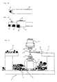
- the most efficient machining method is to form a machining path in a form of one line as shown in Fig. 1A, and to sequentially cut out the machined products such that cutting margins or edges are not remained as much as possible.
- Figs. 1A to 1C show examples in which small chips 2 which will become machined products and which are triangular as viewed from above on a PCD (sintered diamond) disk 1 which is work piece are to be cut out by the wire electrical discharge machine.
- Fig. 1A is a plan view
- Fig. 1B is a side view thereof
- Fig. 1C shows the shape of the small chips obtained by the electrical discharge machine.
- the machining path 4 of the wire electrode with respect to the work piece 1 is formed in a form of one line, and a plurality of machined chips 2 are cut out by this machining path 4.
- a reference number 3 represents machined cutting which were not cut
- a reference number 5 represents a clamp member for grasping a disk 1 of the work piece.
- PCD sintered body disk 1 has a diameter of about 60 to 70 mm and a thickness of about 1.6 to 3.2 mm.
- the machined chip 2 as a product in the cutting machining shown in Fig. 1A is rectangular in shape of about minimum 1 mm, usually about 2 mm ⁇ 4 mm, or triangular in shape of 3 mm in many cases. About 300 pieces of machined chip 2 can be cut and produced from one sheet of disk.
- the machined chips 2 shown in this example are used as a blade on a tip end of a bite 6 of a lathe or used as a blade of an end mill or a reamer 7.
- Machined chips 2 cut out by the electric discharge machining have various shapes as shown in Fig. 2.
- FIG. 4 When machined chips 2 which are small machined products as described above are cut out by cutting machining, as shown in Fig. 4, some of the cut machined chips 2 and machined cuttings 3 drop into a machining tank 8, and other jump by jet stream of machining liquid and scatter onto a work table 9 or the like to which the clamp member 5 which grasps a work piece 1 is mounted.
- reference numbers 10 and 11 respectively represent an upper wire guide and a lower wire guide for guiding a wire electrode 12
- reference numbers 13 and 14 represent a nozzle for jetting machining liquid provided in the upper guide 10 and the lower guide 11 into a machining region.
- machined chips 2 of the machined products are collected manually after completion of all machining operations. Even if one machined chip can be collected for 1 second, if there exists 300 pieces of machined chips, it takes five minutes, which remarkably reduces the operating efficiency. Further, operation for checking in a machining tank 8 thoroughly to confirm if there are any uncollected chips, which takes about 30 minutes or more, is required in the prior art. This confirming operation is a simple operation, which requires patience and causes anguish. Further, in case where various shaped machined chips are machined as described above, whenever different shaped chips are machined, they must be collected, which takes time. If different shaped chips are mixed, it is necessary to distinguish the chips after collection, and this operation is tough.
- the object of the present invention is to provide a wire electrical discharge machine which facilitates collection of machined products cut out by wire electric discharge machining.
- a wire electrical discharge machine of the present invention comprises receiving means for receiving machined chips to be cut out by electric discharge machining.
- the receiving means is disposed so as to cover a portion at least lower than a portion where electric discharge machining is carried out, or both the portion and a side, and the machined chips are prevented from passing through the receiving means, while machining liquid is allowed to pass through the receiving means.
- a wire electrical discharge machine comprises an upper nozzle disposed above a work piece and a lower nozzle disposed below the work piece, in which a wire electrode is inserted between the upper nozzle and the lower nozzle, the wire electrode and the work piece are relatively moved with respect to each other to machine the work piece, thereby forming machined chips, wherein at least the lower nozzle or a lower guide to which the lower nozzle is mounted is provided with lower receiving means for receiving the machined chips, and the lower receiving means prevents the machined chips from passing therethrough and allows machining liquid to pass therethrough.
- This structure makes it easy to collect the machined chips.
- Upper receiving means is mounted to an upper nozzle or an upper guide to which the upper nozzle is mounted so as to be opposed to the lower receiving means, combined receiving means configured by combining lower receiving means and the upper receiving means is formed at least during machining, and the machined chips are received by the combined receiving means.
- the work piece is to be grasped by a clamp member, the combined receiving means receives the work piece and the clamp member which grasps the work piece, and the combined receiving means has a gap for allowing the clamp member to come into and out of the combined receiving means.
- a resilient machined chip-stopping member is provided in the upper receiving means at the gap for preventing the machined chips from jumping out of the combined receiving means through the gap.
- the receiving means has a reticulated or porous structure such that machining liquid passes through the receiving means and the receiving means receives the machined chips.
- At least the lower receiving means is detachably mounted to the lower nozzle or the lower guide to which the lower nozzle is mounted.
- receiving means for receiving machined chips is mounted to the wire nozzle or the wire guide, and the receiving means receives the machined chips.
- the receiving means is mounted to each of the left and right wire nozzles and wire guides, the left and right receiving means are abutted against with each other during machining, and when machined chips are taken out, the left and right receiving means are separated from each other.
- Fig. 5 shows a structure of an essential portion of one embodiment of the present invention.
- This embodiment is different from the conventional wire electrical discharge machine in that a reticulated cage is provided as the receiving means which receives and collects machined chips (machined products) 2 obtained by wire electric discharge machining.
- the cage 20 as the receiving means in this embodiment comprises a combination of a lower cage 21 constituting lower receiving means and an upper cage 22 constituting upper receiving means.
- the lower cage 21 includes a mount portion 21a so that the lower cage 21 can be attachable to and detachable from a nozzle 14 of a lower guide 11 which guides a wire electrode 12.
- the upper cage 22 is mounted to an upper guide 10 (or the upper cage 22 may be detachably mounted to a nozzle 13 mounted to the upper guide 10).
- the upper cage 22 has a notch 22a through which a clamp member 5 which grasps the work piece 1 and which forms a gap which allows the work piece 1 to move for machining.
- the upper cage 22 also includes chip-stopping members 23 which prevent machined chips 2 and machined cuttings 3 from jumping out of the combined receiving means 20 through the notch 22a.
- Resilient foam rubbers are mounted to an upper end peripheral surface of the lower cage 21 and a lower end peripheral surface of the upper cage 22.
- Fig. 6 is a sectional view of the upper cage 22.
- Fig. 7 is a side view of the upper cage 22 as viewed from a right direction in Fig. 5.
- chip-stopping member 23 which prevents the machined chips 2 and machined cuttings 3 from jumping out is provided in the upper cage 22 in front of the notch 22a so as to seal the notch 22a.
- Another chip-stopping member 23 is provided between the notch 22a and the nozzle 13 of the upper guide 10.
- Each of the chip-stopping member 23 is made of resilient material, a lower end of the chip-stopping member 23 is free, and a slit is formed from an intermediate portion to a lower end of the chip-stopping member 23. with this configuration the clamp member 5 which grasps the work piece 1 can move without being hindered by the chip-stopping member 23.
- the upper guide 10 is caused to ascend, and the clamp member 5 is caused to grasp the work piece 1.
- the work table 9 is moved, the clamp member 5 and the work piece 1 are caused to retreat from the upper position of the lower guide 11, the nozzle 14 mounted to the lower guide 11 is inserted into a hole of the mount portion 21a of the lower cage 21, and the lower cage 21 is fixed to the lower guide 11.
- the work table 9 is moved, the work piece 1 is moved to a wire connection position and then, the upper guide 10 is moved to a machining position so that a wire electrode 12 is connected. That is, the wire electrode 12 is allowed to pass through the upper guide 10 and lower guide 11 and is connected in the same manner as that of the prior art.
- the foam rubbers mounted to the lower end peripheral surface of the upper cage 22 and the upper end peripheral surface of the lower cage 21 are brought into tight contact with each other, and they abut against each other without generating a gap.
- the upper cage 22 and lower cage 21 form a space which is opened only at the notch 22a and closed at other portions.
- the work piece 1 grasped by the working clamp 5 is brought into a state shown in Fig. 10 surrounded by the cage 20 which forms the receiving means.
- Fig. 12 shows an outline of a second embodiment of the present invention.
- the second embodiment is different from the first embodiment in that the wire electrode runs horizontally.
- a right guide 30 and a left guide 31 correspond to the upper guide 10 and the lower guide 11 of the first embodiment, respectively.
- the wire electrode 12 is guided by the right and left guides 30 and 31, and the wire electrode 12 runs from right to left in this embodiment.
- Reference numbers 33 and 34 represent nozzles provided on the right and left guides 30 and 31.
- the work piece 1 is clamped in the vertical direction, and moves in a direction perpendicular to a tensile direction of the wire electrode 12. If the tensile direction of the wire electrode 12 is defined as a Z direction, the work piece 1 is allowed to move relatively with respect to the wire electrode in an X axis direction (up-and-down direction in the drawing paper of Fig. 12) which is perpendicular to the Z axis direction, and in a Y axis direction (direction of normal line of the paper sheet).
- a cage 40 constituting the combined receiving means which receives the machined products is also provided in this second embodiment. The cage 40 is divided into left and right cage portions.
- a left cage portion 41 constituting left receiving means is attachable and detachable to and from the left guide 31 or the nozzle 34, and a right cage portion 42 constituting right receiving means is attachable and detachable to and from the right guide 30 or the nozzle 33.
- the clamp member 5 comes in and out of any one of or both of the left and right cage portions 41 and 42. Any one of or both of the left and right cage portions 41 and 42 are provided with notches 45 which form gaps through which the clamp member 5 moves for machining operation.
- the left cage portion 41 is provided with the notch 45. Open side peripheral surfaces of the left and right cage portions 41 and 42 abut air-tightly against each other except position thereof corresponding to the notch 45.
- Lower abutting surfaces of the left and right cage portions 41 and 42 are provided with dividing wall ribs 41a and 42a extending in the vertical direction. Ribs 41b and 42b extending in the vertical direction are provided as chip-stopping members in positions opposed to the notch 45.
- the right guide 30 is caused to move in the Z axis direction to widen a gap between the left and right guides 30 and 31, and the left cage portion 41 is mounted to the left guide 31.
- the right cage portion 42 is mounted to the right guide 30.
- the clamp member 5 is caused to grasp a work piece 1, the work piece 1 is moved to an electric discharge machining-starting position, the right guide 30 is moved, the open side peripheral surfaces of the left and right cage portions 41 and 42 are brought into tight abutment against each other as shown in Fig. 12, and the work piece 1 is covered with the cage 40.
- machining is carried out in the state shown in Fig.12, the machining liquid injected from both the nozzles 33 and 34 flows out of the reticulated shape of the cage, and machined chips 2 are prevented from flowing out by the reticulated shape of the cage and then received in the cage 40. At that time, cut-out machined chips are captured by any one of the left and right cage portions 41 and 42. Since the injecting direction of machining liquid is the lateral direction, machined chips 2 are blown in the lateral direction by the jet stream of machining liquid, and are seldom blown in a vertical direction. Therefore, in the second embodiment, it is unnecessary to provide chip-stopping member which closes the notch 45 provided in the case of the first embodiment. It is sufficient to prevent blown machined chips from dispersing by means of the ribs 41b and 42b provided around the notch 45, and the ribs 41b and 42b constitute the chip-stopping member.
- the right guide 30 After completion of electric discharge machining, the right guide 30 is moved rightward in Fig. 12, the wire electrode is cut, and then, the left and right cage portions 41 and 42 are detached from the guides 30 and 31, and the machined chips are collected. Even if the cage 40 is divided into the left and right cage portions 41 and 42, the machined chips in the left and right cage portions 41 and 42 do not fall out of the cage by the wall ribs 41a and 42a. In this case, also, non-machined portion of the work piece 1, which is grasped by the clamp member 5, is collected in the cage 40. Machined chips cut out in this manner are collected and then cleaned for use.
- the cages 20 and 40 constituting the receiving means have reticulated structure in the above embodiments, the cages may be made of porous member instead of the reticulated structure.
- the upper portion of combined receiving means may be made of material other than the reticulated or porous material. That is, in the first embodiment, an upper cage 22 of the upper receiving means may not be of reticulated structure, and.may simply be a cover which simply covers the upper portion and prevents machining liquid and machined chips and the like from jumping out thereof. In the second embodiment also, upper portions of the left and right cages may not be of the reticulated structure, and may be one mace of simple cover members through which machined chips and machining liquid can not pass.
- only the bottom surface of the receiving means may be made of reticulated or porous material, or of material which allows machining liquid to pass therethrough but does not allow machined chips to pass therethrough.
- only the lower receiving means may be provided as receiving means.
- the side wall of the lower receiving means is formed high, and the lower portion and the side portion of a region where electric discharge machining is carried out with the wire electrode 12 and the work piece 1 are covered with this receiving means.
- the cage for detachably mounting cages, constituting the receiving means which are divided into two pieces, to the guide or the nozzle, the cage is provided with mount portion, and the guide or the nozzle is fitted into and mounted to the hole of the mount portion.
- the cage may be mounted to the guide or the nozzle so that they are placed between two divided cage pieces.
- the lower cage 21 is divided at a central line (a line passing through a center of the mount 21a), and, along the each of the divided sides, a wall rib extending in the vertical direction is provided. These wall ribs have a part which hold the guide or the nozzle between them and a part which comes into close contact with each other without generating a gap.
- the present invention it is possible to extremely easily and swiftly collect machined chips of machined product cut out by wire electric discharge machining. Especially when small machined chips such as cutting tools are to be obtained by wire electric discharge machining, collecting operation of the machined chips are remarkably facilitated as compared with the prior art.
- a machine tool is required to machine at high speed and efficiently, demand of the PCD and CBN tools in a machine tool is increased, and cutting-out working in wire electric discharge machining of blank machining is required to increase speed, efficiency and automatization.
- the present invention meets such requirements, and it is possible to easily and swiftly collect machined chips after machining operation, and the efficiency of machining operation is enhanced.
Landscapes
- Chemical & Material Sciences (AREA)
- Chemical Kinetics & Catalysis (AREA)
- Electrochemistry (AREA)
- Engineering & Computer Science (AREA)
- Mechanical Engineering (AREA)
- Electrical Discharge Machining, Electrochemical Machining, And Combined Machining (AREA)
Abstract
Description
Claims (9)
- A wire electrical discharge machine in which voltage is applied between a stretched wire electrode and a work piece, machining liquid is injected between the wire electrode and the work piece, electricity is discharged between said wire electrode and said work piece while moving said wire electrode relative to said work piece, thereby machining said work piece to form machined chips, wherein
receiving means for receiving said machined chips, which covers at least a portion lower than, or both lower than and a side of, the portion where electric discharge machining is carried out, is disposed,
said receiving means preventing said machined chips from passing through and allowing to said machining liquid to pass through. - A wire electrical discharge machine comprising an upper nozzle disposed above a work piece and a lower nozzle disposed below said work piece, in which a wire electrode is inserted between said upper nozzle and said lower nozzle, and said wire electrode moves relative to said work piece to machine said work piece, thereby forming machined chips, wherein
lower receiving means for receiving said machined chips are provided to at least said lower nozzle or a lower guide to which said lower nozzle is mounted
said lower receiving means preventing said machined chips from passing through and allowing machining liquid to pass through. - The wire electrical discharge machine according to claim 2, wherein upper receiving means is mounted to an upper nozzle or an upper guide to which said upper nozzle is mounted so as to be opposed to said lower receiving means, combined receiving means configured by combining said lower receiving means and said upper receiving means is formed at least during machining, and said machined chips are received by said combined receiving means.
- The wire electrical discharge machine according to claim 3, wherein said combined receiving means receives said work piece and a clamp member which grasps said work piece, and said combined receiving means has a gap for allowing said clamp member to come into and out of said combined receiving means.
- The wire electrical discharge machine according to claim 4, wherein a resilient machined chip-stopping member is provided in an upper receiving means at said gap for preventing said machined chips from jumping out of the combined receiving means through said gap.
- The wire electrical discharge machine according to any one of claims 2 to 5, wherein said receiving means has a reticulated or porous structure such that machining liquid passes through said receiving means while said receiving means receives said machined chips.
- The wire electrical discharge machine according to any one of claims 2 to 6, wherein said lower receiving means is detachably mounted to said lower nozzle or said lower guide to which said lower nozzle is mounted.
- A wire electrical discharge machine in which a wire nozzle and a wire guide are disposed laterally in a horizontal direction, a wire electrode horizontally held by said wire guide moves relative to a vertically clamped work piece to machine said work piece, thereby generating machined chips, wherein
receiving means for receiving machined chips is mounted to said wire nozzle or said wire guide,
said receiving means preventing said machined chips from passing therethrough and allowing machining liquid to pass therethrough. - The wire electrical discharge machine according to claim 8, wherein said receiving means is mounted to each of said left and right wire nozzle and wire guide, the left and right receiving means are abutted against with each other during machining, and when machined chips are taken out, the left and right receiving means are separated from each other.
Applications Claiming Priority (2)
| Application Number | Priority Date | Filing Date | Title |
|---|---|---|---|
| JP2001066841 | 2001-03-09 | ||
| JP2001066841A JP3576988B2 (en) | 2001-03-09 | 2001-03-09 | Wire electric discharge machine |
Publications (2)
| Publication Number | Publication Date |
|---|---|
| EP1238739A2 true EP1238739A2 (en) | 2002-09-11 |
| EP1238739A3 EP1238739A3 (en) | 2005-02-09 |
Family
ID=18925283
Family Applications (1)
| Application Number | Title | Priority Date | Filing Date |
|---|---|---|---|
| EP02251602A Withdrawn EP1238739A3 (en) | 2001-03-09 | 2002-03-07 | WIre electrical discharge machine |
Country Status (3)
| Country | Link |
|---|---|
| US (1) | US6642468B2 (en) |
| EP (1) | EP1238739A3 (en) |
| JP (1) | JP3576988B2 (en) |
Cited By (3)
| Publication number | Priority date | Publication date | Assignee | Title |
|---|---|---|---|---|
| EP1473104A1 (en) * | 2003-05-02 | 2004-11-03 | Fanuc Ltd | Wire electric discharge machine |
| CN107262852A (en) * | 2016-04-05 | 2017-10-20 | 西部电机株式会社 | Cut substrate recovery method, wire electric discharge machine and cut substrate retracting device |
| CN116786920B (en) * | 2023-08-28 | 2023-11-28 | 赫比(成都)精密塑胶制品有限公司 | Electric spark machining method and machining equipment |
Families Citing this family (6)
| Publication number | Priority date | Publication date | Assignee | Title |
|---|---|---|---|---|
| JP2005211990A (en) | 2004-01-27 | 2005-08-11 | Fanuc Ltd | Wire-cut electric discharge machine |
| JP5199447B1 (en) * | 2011-12-09 | 2013-05-15 | ファナック株式会社 | Wire electrical discharge machine with rotating shaft |
| WO2013111323A1 (en) * | 2012-01-27 | 2013-08-01 | 三菱電機株式会社 | Wire discharge processing machine and wire electrode elimination device |
| JP6484148B2 (en) * | 2015-09-03 | 2019-03-13 | ファナック株式会社 | Machining program creation device for wire electric discharge machine |
| JP7457106B2 (en) * | 2020-04-20 | 2024-03-27 | ファナック株式会社 | Workpiece exchange jig and cutting system |
| CN115055765A (en) * | 2022-07-19 | 2022-09-16 | 杨如珍 | Electric spark numerical control forming machine tool and using method thereof |
Family Cites Families (8)
| Publication number | Priority date | Publication date | Assignee | Title |
|---|---|---|---|---|
| US4387286A (en) * | 1980-03-26 | 1983-06-07 | Inoue-Japax Research Incorporated | Apparatus for controlling splashes and purification of a machining liquid |
| JPS5988218A (en) * | 1982-11-11 | 1984-05-22 | Inoue Japax Res Inc | Electric discharge machining |
| JPS624517A (en) * | 1985-06-28 | 1987-01-10 | Inoue Japax Res Inc | Electric discharge machine |
| JPH03287313A (en) * | 1990-03-31 | 1991-12-18 | Seibu Electric & Mach Co Ltd | Work chip removing device for wire electric discharge machine |
| JPH0457623A (en) * | 1990-06-25 | 1992-02-25 | Mitsubishi Electric Corp | Wire-cut electric discharge machine |
| JPH07108419A (en) * | 1993-10-08 | 1995-04-25 | Sodick Co Ltd | Electric discharge machining device and electric discharge machining method using this device |
| JPH09216130A (en) * | 1996-02-09 | 1997-08-19 | Seibu Electric & Mach Co Ltd | Machining liquid supply device for machining tank in immersion wire electric discharge machine |
| JP3287313B2 (en) | 1998-08-19 | 2002-06-04 | 豊丸産業株式会社 | Pachinko machine |
-
2001
- 2001-03-09 JP JP2001066841A patent/JP3576988B2/en not_active Expired - Lifetime
-
2002
- 2002-03-06 US US10/091,316 patent/US6642468B2/en not_active Expired - Lifetime
- 2002-03-07 EP EP02251602A patent/EP1238739A3/en not_active Withdrawn
Cited By (4)
| Publication number | Priority date | Publication date | Assignee | Title |
|---|---|---|---|---|
| EP1473104A1 (en) * | 2003-05-02 | 2004-11-03 | Fanuc Ltd | Wire electric discharge machine |
| US6884957B2 (en) | 2003-05-02 | 2005-04-26 | Fanuc Limited | Wire electric discharge machine |
| CN107262852A (en) * | 2016-04-05 | 2017-10-20 | 西部电机株式会社 | Cut substrate recovery method, wire electric discharge machine and cut substrate retracting device |
| CN116786920B (en) * | 2023-08-28 | 2023-11-28 | 赫比(成都)精密塑胶制品有限公司 | Electric spark machining method and machining equipment |
Also Published As
| Publication number | Publication date |
|---|---|
| US6642468B2 (en) | 2003-11-04 |
| EP1238739A3 (en) | 2005-02-09 |
| JP3576988B2 (en) | 2004-10-13 |
| JP2002263958A (en) | 2002-09-17 |
| US20020125218A1 (en) | 2002-09-12 |
Similar Documents
| Publication | Publication Date | Title |
|---|---|---|
| DE602005001144T2 (en) | cutting tool | |
| US20010007215A1 (en) | Cutting tool and cutting process | |
| US6642468B2 (en) | Wire cutting electric discharge machine with collection of machined chips | |
| DE102014206920A1 (en) | Laser processing device | |
| JP2010099810A (en) | Machine tool processing powder discharge device | |
| WO2016151623A1 (en) | Tip dresser | |
| EP2908993B1 (en) | Fluid jet receiving receptacles and related fluid jet cutting systems and methods | |
| US7437816B1 (en) | Lathe with arrangement for dropping chips into a container without blocking moving path of a saddle | |
| US20120020748A1 (en) | Tool of machine tool | |
| CA1220928A (en) | Machine tool | |
| JPH05115937A (en) | Lead wire cutter | |
| DE19517548C1 (en) | Device for the electrical discharge machining of workpieces | |
| WO2012045399A1 (en) | Abrasive cutting-off device with dust extraction | |
| JP2004202504A (en) | Chip recovery equipment in chip dresser | |
| CN215965277U (en) | Equipment for cleaning workpiece by using dry ice | |
| CN220679520U (en) | Steel band processing trimming machine | |
| CN212527145U (en) | Sheet metal component welding seam equipment of polishing | |
| CN214350012U (en) | Steel band deburring device | |
| US20040255744A1 (en) | Cutting blade and method of making the same | |
| CN106553128B (en) | A sweeps collection device and sharpening machine for electrode cap coping | |
| DE4002568A1 (en) | Swarf removal extractor for saw - blows dust into exhausting air current from accumulation area | |
| CN215969523U (en) | Brittle thin-wall material pipe cutting device | |
| CN211028448U (en) | Protective device for wire cut electric discharge machine | |
| CN214291171U (en) | Steel band deckle edge repair mechanism | |
| KR101301973B1 (en) | structure for tool box in milling machine |
Legal Events
| Date | Code | Title | Description |
|---|---|---|---|
| PUAI | Public reference made under article 153(3) epc to a published international application that has entered the european phase |
Free format text: ORIGINAL CODE: 0009012 |
|
| AK | Designated contracting states |
Kind code of ref document: A2 Designated state(s): AT BE CH CY DE DK ES FI FR GB GR IE IT LI LU MC NL PT SE TR |
|
| AX | Request for extension of the european patent |
Free format text: AL;LT;LV;MK;RO;SI |
|
| PUAL | Search report despatched |
Free format text: ORIGINAL CODE: 0009013 |
|
| AK | Designated contracting states |
Kind code of ref document: A3 Designated state(s): AT BE CH CY DE DK ES FI FR GB GR IE IT LI LU MC NL PT SE TR |
|
| AX | Request for extension of the european patent |
Extension state: AL LT LV MK RO SI |
|
| RIC1 | Information provided on ipc code assigned before grant |
Ipc: 7B 23H 1/10 B Ipc: 7B 23H 7/36 B Ipc: 7B 23H 7/02 B Ipc: 7B 23H 11/00 B Ipc: 7B 23H 7/10 A |
|
| 17P | Request for examination filed |
Effective date: 20050609 |
|
| AKX | Designation fees paid |
Designated state(s): CH LI |
|
| REG | Reference to a national code |
Ref country code: DE Ref legal event code: 8566 |
|
| 17Q | First examination report despatched |
Effective date: 20061115 |
|
| GRAP | Despatch of communication of intention to grant a patent |
Free format text: ORIGINAL CODE: EPIDOSNIGR1 |
|
| STAA | Information on the status of an ep patent application or granted ep patent |
Free format text: STATUS: THE APPLICATION IS DEEMED TO BE WITHDRAWN |
|
| RAP1 | Party data changed (applicant data changed or rights of an application transferred) |
Owner name: FANUC CORPORATION |
|
| 18D | Application deemed to be withdrawn |
Effective date: 20100916 |