EP1237792B1 - Collapsible secure container - Google Patents
Collapsible secure container Download PDFInfo
- Publication number
- EP1237792B1 EP1237792B1 EP00993571A EP00993571A EP1237792B1 EP 1237792 B1 EP1237792 B1 EP 1237792B1 EP 00993571 A EP00993571 A EP 00993571A EP 00993571 A EP00993571 A EP 00993571A EP 1237792 B1 EP1237792 B1 EP 1237792B1
- Authority
- EP
- European Patent Office
- Prior art keywords
- sheet members
- primary
- tray
- sheet member
- along
- Prior art date
- Legal status (The legal status is an assumption and is not a legal conclusion. Google has not performed a legal analysis and makes no representation as to the accuracy of the status listed.)
- Expired - Lifetime
Links
- 230000037431 insertion Effects 0.000 claims description 4
- 238000003780 insertion Methods 0.000 claims description 4
- 230000015572 biosynthetic process Effects 0.000 abstract description 2
- 238000005755 formation reaction Methods 0.000 abstract 1
- 230000007246 mechanism Effects 0.000 description 4
- 229910000831 Steel Inorganic materials 0.000 description 2
- 239000010959 steel Substances 0.000 description 2
- XAGFODPZIPBFFR-UHFFFAOYSA-N aluminium Chemical compound [Al] XAGFODPZIPBFFR-UHFFFAOYSA-N 0.000 description 1
- 229910052782 aluminium Inorganic materials 0.000 description 1
- 239000004411 aluminium Substances 0.000 description 1
- 230000007797 corrosion Effects 0.000 description 1
- 238000005260 corrosion Methods 0.000 description 1
- 239000011152 fibreglass Substances 0.000 description 1
- 239000000463 material Substances 0.000 description 1
- 239000004033 plastic Substances 0.000 description 1
Images
Classifications
-
- E—FIXED CONSTRUCTIONS
- E05—LOCKS; KEYS; WINDOW OR DOOR FITTINGS; SAFES
- E05G—SAFES OR STRONG-ROOMS FOR VALUABLES; BANK PROTECTION DEVICES; SAFETY TRANSACTION PARTITIONS
- E05G1/00—Safes or strong-rooms for valuables
-
- E—FIXED CONSTRUCTIONS
- E05—LOCKS; KEYS; WINDOW OR DOOR FITTINGS; SAFES
- E05G—SAFES OR STRONG-ROOMS FOR VALUABLES; BANK PROTECTION DEVICES; SAFETY TRANSACTION PARTITIONS
- E05G1/00—Safes or strong-rooms for valuables
- E05G1/02—Details
- E05G1/024—Wall or panel structure
Definitions
- This invention relates to a collapsible secure container for open-backed motor vehicles or the like including boats, trailers, hotel rooms, lockers motor cycles.
- US-A-3611994 discloses a foldable animal shipping container having a rigid bottom and upstanding sides of different height, each side having a hinged wall to form an enclosure with one of the walls including a hinged top.
- the container which may be provided in a variety of sizes, may also find application in boats, trailers, hotel rooms, lockers and even motor cycles.
- a collapsible container comprising:
- the tray is adapted to be anchored to a fixed structure, typically a wall of a bakkie, light delivery vehicle of the like.
- the tray may include one or more holes therein for receiving bolts or the like fasteners to secure the container in place.
- the primary sheet members include along at least two opposed free edges thereof, a short flange. This prevents the insertion of a screwdriver or other lever like tool in an attempt to pry open the container.
- the secondary sheet member includes a flange along a third free edge thereof.
- the tray preferably comprises the rear wall of the container with the sheet member hinged to the upper edge thereof forming the top panel or lid of the container, and the primary sheet member along the lower edge thereof forming the base of the container. It is to this (base) sheet member that the secondary sheet member is hinged, this secondary sheet member forming the front wall and including a locking mechanism for engaging the lid.
- the lid includes an angled section extending at least part of the width of the front wall sheet member to form a channel. This receives the flange along the third edge of the front wall and provides in some instances a locking surface for the locking mechanism.
- the locking mechanism may comprise a cam lock or in an alternative form, a safe-lock.
- the flanges along the top edges of the side wall sheet members may each include a simple catch for engaging the flange along the third edge of the front wall. This prevents the front wall pivoting flat into the interior of the box during assembly.
- the flanges along the bottom edges of the side walls include recesses for receiving integral pins on the underside of the base sheet member.
- the tray In order to assemble the container from its folded condition, the tray is arranged (if not affixed to the rear wall of the cab) in an upright position.
- the lid sheet member is pivoted vertically away from the front of the tray and then the side wall sheet members are swung outwards.
- the base sheet member is lowered to the ground and the front wall (or secondary) sheet member is swung upwardly and outwardly.
- the side walls are swung inwardly to engage the pins on the underside of the base and once secured, the lid is lowered to rest upon the two side walls. Thereafter, the front wall is raised to engage the side wall catches and the lid to form a closed box. The box may then be locked.
- the box In order to disassemble, the box is unlocked and the lid lifted. Thereafter, the side wall catches are released allowing the front wall to pivot inwardly to rest upon the base. The side walls are swung outwardly to permit folding of the base up into the tray and then the side walls are swung inwardly into the tray before the lid pivots down to contain the collapsed box within the tray.
- the container may comprise a variety of materials including steel, aluminium, plastic or fibreglass.
- the typical galvanlsed steel will be used to provide a very secure container which is not susceptible to corrosion.
- a collapsible container 10 includes a tray 12 having primary sheet members 14, 16 and 18a and b hinged thereto to form the lid, base and side walls respectively of a box when assembled.
- the base primary sheet member 16 is further hinged at 20 to a secondary sheet member 22 which forms the front wall of the box.
- the hinge is secured to a flange 24 on base 16.
- the tray 12 is anchored to a wall or other fixed surface, but the main object of the invention is that the tray is secured at a suitable point to a wall in the bin of a vehicle.
- Different versions may be used as hotel wall safes, or secure storage areas In trallers, boats or lockers.
- All the sheet members have flanges 20, 24, 26, 28 to prevent insertion of articles in an attempt to access the locked box.
- Flange 28 of the secondary sheet member (22) is insert into a channel formation 30 formed along the front edge of the lid. The rear of the channel may form a locking surface for engaging locking arm 32.
- Pins 34 are provided to secure the side walls to the base.
- Catch mechanisms 36 are provided to secure the front wall to the side walls.
Landscapes
- Closures For Containers (AREA)
- Vehicle Step Arrangements And Article Storage (AREA)
- Pallets (AREA)
- Materials For Medical Uses (AREA)
- Collation Of Sheets And Webs (AREA)
Abstract
Description
- This invention relates to a collapsible secure container for open-backed motor vehicles or the like including boats, trailers, hotel rooms, lockers motor cycles.
- Incidences of theft from vehicles and other high risk areas which cannot be adequately secured, has increased substantially in recent times. However space is limited in the bins of light delivery vehicles and although people have taken to storing individual items within secure containers in the bins, these tend to be bulky and must be periodically removed when not in use. Further, this does not prevent the container being moved, although size and weight may limit such unauthorised removal.
- US-A-3611994 discloses a foldable animal shipping container having a rigid bottom and upstanding sides of different height, each side having a hinged wall to form an enclosure with one of the walls including a hinged top.
- It is an object of this invention to provide a secure container which may be permanently anchored to the vehicle and which is further adapted to the vehicle and which further is adapted to collapse for convenient storage when not in use. The container which may be provided in a variety of sizes, may also find application in boats, trailers, hotel rooms, lockers and even motor cycles.
- According to one aspect of the invention, there is provided a collapsible container, comprising:
- a tray with walls;
- primary sheet members hinged to the walls of the tray,
- one of the primary sheet members being a base sheet member; and
- a secondary sheet member hinged along an edge to the base sheet member, the second sheet member serving as a front access member of an assembled closed box;
- short flanges extending along at least two opposed free edges of the primary sheet members, the short flanges extending towards each other to overlay a zone of abutment of adjacent primary sheet members to prevent insertion of a prying instrument thereby preventing an inserted prying instrument forcibly opening the container; and
- a box lock, wherein,
- in a first position, the primary and secondary sheet members are pivotably positioned so all of the sheet members, except one exception member, are accommodated with the tray, the exception member forming a lid for the tray,
- in a second position, the primary and secondary sheet members form walls of the assembled closed box,
- the box lock locks the closed box, and
- the short flanges Including recesses for receiving integral pins on the underside of the base sheet member for releasably engaging adjacent ones of the primary sheet members,
- In the preferred form of the invention, the tray is adapted to be anchored to a fixed structure, typically a wall of a bakkie, light delivery vehicle of the like. The tray may include one or more holes therein for receiving bolts or the like fasteners to secure the container in place.
- Also in the preferred form of the invention the primary sheet members include along at least two opposed free edges thereof, a short flange. This prevents the insertion of a screwdriver or other lever like tool in an attempt to pry open the container.
- Also in the preferred form, the secondary sheet member includes a flange along a third free edge thereof.
- The tray preferably comprises the rear wall of the container with the sheet member hinged to the upper edge thereof forming the top panel or lid of the container, and the primary sheet member along the lower edge thereof forming the base of the container. It is to this (base) sheet member that the secondary sheet member is hinged, this secondary sheet member forming the front wall and including a locking mechanism for engaging the lid. In one form the lid includes an angled section extending at least part of the width of the front wall sheet member to form a channel. This receives the flange along the third edge of the front wall and provides in some instances a locking surface for the locking mechanism. The locking mechanism may comprise a cam lock or in an alternative form, a safe-lock.
- In one form, the flanges along the top edges of the side wall sheet members may each include a simple catch for engaging the flange along the third edge of the front wall. This prevents the front wall pivoting flat into the interior of the box during assembly.
- In the preferred form, the flanges along the bottom edges of the side walls include recesses for receiving integral pins on the underside of the base sheet member.
- In order to assemble the container from its folded condition, the tray is arranged (if not affixed to the rear wall of the cab) in an upright position. The lid sheet member is pivoted vertically away from the front of the tray and then the side wall sheet members are swung outwards. The base sheet member is lowered to the ground and the front wall (or secondary) sheet member is swung upwardly and outwardly. The side walls are swung inwardly to engage the pins on the underside of the base and once secured, the lid is lowered to rest upon the two side walls. Thereafter, the front wall is raised to engage the side wall catches and the lid to form a closed box. The box may then be locked.
- In order to disassemble, the box is unlocked and the lid lifted. Thereafter, the side wall catches are released allowing the front wall to pivot inwardly to rest upon the base. The side walls are swung outwardly to permit folding of the base up into the tray and then the side walls are swung inwardly into the tray before the lid pivots down to contain the collapsed box within the tray.
- The container may comprise a variety of materials including steel, aluminium, plastic or fibreglass. The typical galvanlsed steel will be used to provide a very secure container which is not susceptible to corrosion.
- An embodiment of the invention is described below with reference to the accompanying drawings in which:
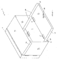
- Figure 1 is an isometric front and side view of a container, partially assembled, according to the invention;
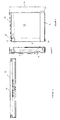
- Figure 2 is a side view of an assembled container;
- Figure 3 is a side view of the container in a collapsed condition; and
- Figure 4 is a top view of the side panels in the collapsed condition.
- In the drawings, a
collapsible container 10 includes atray 12 havingprimary sheet members - The base
primary sheet member 16 is further hinged at 20 to a secondary sheet member 22 which forms the front wall of the box. The hinge is secured to aflange 24 onbase 16. - Typically the
tray 12 is anchored to a wall or other fixed surface, but the main object of the invention is that the tray is secured at a suitable point to a wall in the bin of a vehicle. Different versions may be used as hotel wall safes, or secure storage areas In trallers, boats or lockers. - All the sheet members have
flanges Flange 28 of the secondary sheet member (22) is insert into achannel formation 30 formed along the front edge of the lid. The rear of the channel may form a locking surface forengaging locking arm 32. -
Pins 34 are provided to secure the side walls to the base. -
Catch mechanisms 36 are provided to secure the front wall to the side walls.
wherein the lid includes an angled section extending at least partly along a width of the lid to form a channel for receiving the flange along the third free edge of the secondary sheet member.
Claims (1)
- A collapsible container (10), comprising:a tray (12) with walls;primary sheet members (14, 16, 18a, 18b) hinged to the walls of the tray,one of the primary sheet members (16) being a base sheet member; anda secondary sheet member (22) hinged along an edge to the base sheet member (16), the second sheet member (22) serving as a front access member of an assembled closed box;flanges (26) extending along free edges of the primary sheet members (14, 18a, 18b), the flanges (26) extending towards each other to overlay a zone of abutment of adjacent primary sheet members to prevent insertion of a prying instrument thereby preventing an inserted prying instrument forcibly opening the container; anda box lock (32), wherein,in a first position collapsed, the primary and secondary sheet members are pivotably positioned so all of the sheet members, except one exception member, are accommodated with the tray (12), the exception member forming a lid (14) for the tray (12),in a second position, the primary and secondary sheet members form walls of the assembled closed box,the box lock locks the closed box, andthe flanges along the bottom edges of the primary sheet members (18a, 18b) including recesses for receiving integral pins (34) on the underside of the base sheet member for releasably engaging adjacent ones of the primary sheet members (18a, 18b),characterised in that the secondary sheet member (22) includes a flange (28) along a third free edge thereof extending into the interior of the closed box to prevent forcible opening, and
the lid includes an angled section extending at least partly along a width of the lid to form a channel (30) for receiving the flange (28) along the third free edge of the secondary sheet member.
Applications Claiming Priority (3)
| Application Number | Priority Date | Filing Date | Title |
|---|---|---|---|
| ZA9907149 | 1999-11-17 | ||
| ZA997149 | 1999-11-17 | ||
| PCT/ZA2000/000216 WO2001054989A2 (en) | 1999-11-17 | 2000-11-16 | Collapsible secure container |
Publications (2)
| Publication Number | Publication Date |
|---|---|
| EP1237792A2 EP1237792A2 (en) | 2002-09-11 |
| EP1237792B1 true EP1237792B1 (en) | 2006-05-24 |
Family
ID=25587996
Family Applications (1)
| Application Number | Title | Priority Date | Filing Date |
|---|---|---|---|
| EP00993571A Expired - Lifetime EP1237792B1 (en) | 1999-11-17 | 2000-11-16 | Collapsible secure container |
Country Status (7)
| Country | Link |
|---|---|
| US (1) | US6935526B1 (en) |
| EP (1) | EP1237792B1 (en) |
| CN (1) | CN1315694C (en) |
| AT (1) | ATE327172T1 (en) |
| AU (1) | AU778275B2 (en) |
| DE (1) | DE60028238T2 (en) |
| WO (1) | WO2001054989A2 (en) |
Families Citing this family (10)
| Publication number | Priority date | Publication date | Assignee | Title |
|---|---|---|---|---|
| AU302923S (en) * | 2005-03-10 | 2005-08-26 | Collapsible container | |
| US20060213150A1 (en) * | 2005-03-24 | 2006-09-28 | Sonon James A | Method for product handling using a configurable display container |
| US7708160B2 (en) * | 2006-01-10 | 2010-05-04 | United States Postal Service | Collapsible container |
| CN101397075B (en) * | 2007-09-27 | 2012-07-04 | 中国国际海运集装箱(集团)股份有限公司 | Foldable dress transportation box |
| US20100282136A1 (en) * | 2009-05-08 | 2010-11-11 | Robert Stanley | Portable vault |
| US10137754B2 (en) * | 2014-09-26 | 2018-11-27 | James Sheridan | Expandable refrigeration system for vehicles |
| US9689110B2 (en) * | 2014-10-09 | 2017-06-27 | William Yates Massey, Jr. | Collapsible multi-purpose structure |
| CN106886726B (en) * | 2017-03-17 | 2020-10-09 | 南阳师范学院 | A computer network information security control device |
| US10582693B1 (en) * | 2017-09-12 | 2020-03-10 | Simon Kazanchyan | Dog kennel and sofa |
| US12319242B2 (en) * | 2023-11-07 | 2025-06-03 | Brian Goldwitz | Truck storage and securing apparatus |
Family Cites Families (8)
| Publication number | Priority date | Publication date | Assignee | Title |
|---|---|---|---|---|
| US221504A (en) * | 1879-11-11 | Improvement in automatic fire-extinguishers | ||
| US2221504A (en) | 1937-11-17 | 1940-11-12 | Beasley | Box and the like |
| FR1062713A (en) | 1952-06-10 | 1954-04-27 | Collapsible transport container | |
| DE1040448B (en) * | 1957-01-26 | 1958-10-02 | Fazit Ges Fuer Transporttechni | Collapsible transport container |
| GB1080290A (en) * | 1965-03-02 | 1967-08-23 | Lorne Ralph Sinclair | Improvements in or relating to a folding crate |
| US3611994A (en) * | 1969-08-13 | 1971-10-12 | Everett R Bailey | Foldable animal shipping container |
| DE4218408A1 (en) * | 1992-06-04 | 1992-12-17 | Edmund Wrede | Collapsible aluminium@ transport container - comprises only six parts including lid with links for collapsing formed by parts themselves |
| US6155444A (en) * | 2000-01-19 | 2000-12-05 | Green Wheel Industrial Co., Ltd. | Collapsible plastic container |
-
2000
- 2000-11-16 EP EP00993571A patent/EP1237792B1/en not_active Expired - Lifetime
- 2000-11-16 CN CNB008175977A patent/CN1315694C/en not_active Expired - Fee Related
- 2000-11-16 WO PCT/ZA2000/000216 patent/WO2001054989A2/en not_active Ceased
- 2000-11-16 AT AT00993571T patent/ATE327172T1/en not_active IP Right Cessation
- 2000-11-16 DE DE60028238T patent/DE60028238T2/en not_active Expired - Fee Related
- 2000-11-16 US US10/130,432 patent/US6935526B1/en not_active Expired - Fee Related
- 2000-11-16 AU AU63519/01A patent/AU778275B2/en not_active Ceased
Also Published As
| Publication number | Publication date |
|---|---|
| CN1460084A (en) | 2003-12-03 |
| US6935526B1 (en) | 2005-08-30 |
| CN1315694C (en) | 2007-05-16 |
| WO2001054989A3 (en) | 2002-05-16 |
| EP1237792A2 (en) | 2002-09-11 |
| AU6351901A (en) | 2001-08-07 |
| AU778275B2 (en) | 2004-11-25 |
| DE60028238T2 (en) | 2007-03-29 |
| WO2001054989A2 (en) | 2001-08-02 |
| DE60028238D1 (en) | 2006-06-29 |
| ATE327172T1 (en) | 2006-06-15 |
Similar Documents
| Publication | Publication Date | Title |
|---|---|---|
| US5488914A (en) | Security device for boxes | |
| US4828312A (en) | Collapsible security storage apparatus for truck beds | |
| US8152014B2 (en) | Collapsible container system | |
| US5088636A (en) | Rolling tool box | |
| US6540134B1 (en) | Parcel box | |
| US7073677B2 (en) | Secure trash container assembly | |
| US7165695B2 (en) | Dispensing container for dispensing fasteners | |
| US6644710B2 (en) | Box container and loading space for a motor vehicle | |
| US4288134A (en) | Storage cabinet | |
| EP1237792B1 (en) | Collapsible secure container | |
| US7392993B1 (en) | Container for storing, securing and transporting articles | |
| US11666169B1 (en) | Package receiving device | |
| US5915618A (en) | Anti-theft mailbox insert | |
| US5850967A (en) | Security mailbox | |
| US10538941B2 (en) | Locks for storage containers and the like | |
| US20030075476A1 (en) | Storage and transport system for collapsible tradeshow displays | |
| CA2352300A1 (en) | Recorded media security container | |
| US6851771B2 (en) | Lockable wire enclosure and locking mechanism therefor | |
| US12213608B2 (en) | Parcel boxes having baffle assemblies and methods | |
| US20040032190A1 (en) | Multi-modal wall mountable storage cabinet with drop down table | |
| US20100147838A1 (en) | Secure storage chamber | |
| US9463751B1 (en) | Storage container for a truck bed | |
| US4066158A (en) | Chute construction | |
| US6845875B2 (en) | Convertible cargo box-bed liner for sports utility vehicle, van, or pick-up truck | |
| GB2105399A (en) | Security box or cabinet |
Legal Events
| Date | Code | Title | Description |
|---|---|---|---|
| PUAI | Public reference made under article 153(3) epc to a published international application that has entered the european phase |
Free format text: ORIGINAL CODE: 0009012 |
|
| AK | Designated contracting states |
Kind code of ref document: A2 Designated state(s): AT BE CH CY DE DK ES FI FR GB GR IE IT LI LU MC NL PT SE TR |
|
| AX | Request for extension of the european patent |
Free format text: AL;LT;LV;MK;RO;SI |
|
| 17P | Request for examination filed |
Effective date: 20020617 |
|
| 17Q | First examination report despatched |
Effective date: 20041213 |
|
| GRAP | Despatch of communication of intention to grant a patent |
Free format text: ORIGINAL CODE: EPIDOSNIGR1 |
|
| GRAS | Grant fee paid |
Free format text: ORIGINAL CODE: EPIDOSNIGR3 |
|
| GRAA | (expected) grant |
Free format text: ORIGINAL CODE: 0009210 |
|
| AK | Designated contracting states |
Kind code of ref document: B1 Designated state(s): AT BE CH CY DE DK ES FI FR GB GR IE IT LI LU MC NL PT SE TR |
|
| PG25 | Lapsed in a contracting state [announced via postgrant information from national office to epo] |
Ref country code: CH Free format text: LAPSE BECAUSE OF FAILURE TO SUBMIT A TRANSLATION OF THE DESCRIPTION OR TO PAY THE FEE WITHIN THE PRESCRIBED TIME-LIMIT Effective date: 20060524 Ref country code: LI Free format text: LAPSE BECAUSE OF FAILURE TO SUBMIT A TRANSLATION OF THE DESCRIPTION OR TO PAY THE FEE WITHIN THE PRESCRIBED TIME-LIMIT Effective date: 20060524 Ref country code: FI Free format text: LAPSE BECAUSE OF FAILURE TO SUBMIT A TRANSLATION OF THE DESCRIPTION OR TO PAY THE FEE WITHIN THE PRESCRIBED TIME-LIMIT Effective date: 20060524 Ref country code: IT Free format text: LAPSE BECAUSE OF FAILURE TO SUBMIT A TRANSLATION OF THE DESCRIPTION OR TO PAY THE FEE WITHIN THE PRESCRIBED TIME-LIMIT;WARNING: LAPSES OF ITALIAN PATENTS WITH EFFECTIVE DATE BEFORE 2007 MAY HAVE OCCURRED AT ANY TIME BEFORE 2007. THE CORRECT EFFECTIVE DATE MAY BE DIFFERENT FROM THE ONE RECORDED. Effective date: 20060524 |
|
| REG | Reference to a national code |
Ref country code: GB Ref legal event code: FG4D |
|
| REG | Reference to a national code |
Ref country code: CH Ref legal event code: EP |
|
| REG | Reference to a national code |
Ref country code: IE Ref legal event code: FG4D |
|
| REF | Corresponds to: |
Ref document number: 60028238 Country of ref document: DE Date of ref document: 20060629 Kind code of ref document: P |
|
| PG25 | Lapsed in a contracting state [announced via postgrant information from national office to epo] |
Ref country code: DK Free format text: LAPSE BECAUSE OF FAILURE TO SUBMIT A TRANSLATION OF THE DESCRIPTION OR TO PAY THE FEE WITHIN THE PRESCRIBED TIME-LIMIT Effective date: 20060824 |
|
| PG25 | Lapsed in a contracting state [announced via postgrant information from national office to epo] |
Ref country code: ES Free format text: LAPSE BECAUSE OF FAILURE TO SUBMIT A TRANSLATION OF THE DESCRIPTION OR TO PAY THE FEE WITHIN THE PRESCRIBED TIME-LIMIT Effective date: 20060904 |
|
| REG | Reference to a national code |
Ref country code: SE Ref legal event code: TRGR |
|
| PG25 | Lapsed in a contracting state [announced via postgrant information from national office to epo] |
Ref country code: PT Free format text: LAPSE BECAUSE OF FAILURE TO SUBMIT A TRANSLATION OF THE DESCRIPTION OR TO PAY THE FEE WITHIN THE PRESCRIBED TIME-LIMIT Effective date: 20061024 |
|
| PGFP | Annual fee paid to national office [announced via postgrant information from national office to epo] |
Ref country code: IE Payment date: 20061116 Year of fee payment: 7 |
|
| PGFP | Annual fee paid to national office [announced via postgrant information from national office to epo] |
Ref country code: AT Payment date: 20061121 Year of fee payment: 7 Ref country code: LU Payment date: 20061121 Year of fee payment: 7 |
|
| PGFP | Annual fee paid to national office [announced via postgrant information from national office to epo] |
Ref country code: SE Payment date: 20061129 Year of fee payment: 7 |
|
| PG25 | Lapsed in a contracting state [announced via postgrant information from national office to epo] |
Ref country code: MC Free format text: LAPSE BECAUSE OF NON-PAYMENT OF DUE FEES Effective date: 20061130 |
|
| PGFP | Annual fee paid to national office [announced via postgrant information from national office to epo] |
Ref country code: NL Payment date: 20061130 Year of fee payment: 7 |
|
| REG | Reference to a national code |
Ref country code: CH Ref legal event code: PL |
|
| PGFP | Annual fee paid to national office [announced via postgrant information from national office to epo] |
Ref country code: BE Payment date: 20061204 Year of fee payment: 7 |
|
| ET | Fr: translation filed | ||
| PLBE | No opposition filed within time limit |
Free format text: ORIGINAL CODE: 0009261 |
|
| STAA | Information on the status of an ep patent application or granted ep patent |
Free format text: STATUS: NO OPPOSITION FILED WITHIN TIME LIMIT |
|
| 26N | No opposition filed |
Effective date: 20070227 |
|
| PGFP | Annual fee paid to national office [announced via postgrant information from national office to epo] |
Ref country code: IT Payment date: 20071115 Year of fee payment: 8 |
|
| PG25 | Lapsed in a contracting state [announced via postgrant information from national office to epo] |
Ref country code: GR Free format text: LAPSE BECAUSE OF FAILURE TO SUBMIT A TRANSLATION OF THE DESCRIPTION OR TO PAY THE FEE WITHIN THE PRESCRIBED TIME-LIMIT Effective date: 20060825 |
|
| PGFP | Annual fee paid to national office [announced via postgrant information from national office to epo] |
Ref country code: FR Payment date: 20071122 Year of fee payment: 8 Ref country code: GB Payment date: 20071113 Year of fee payment: 8 |
|
| PGFP | Annual fee paid to national office [announced via postgrant information from national office to epo] |
Ref country code: DE Payment date: 20080131 Year of fee payment: 8 |
|
| BERE | Be: lapsed |
Owner name: *LAGGAR JEFFREY EDWARD Effective date: 20071130 |
|
| EUG | Se: european patent has lapsed | ||
| PG25 | Lapsed in a contracting state [announced via postgrant information from national office to epo] |
Ref country code: TR Free format text: LAPSE BECAUSE OF FAILURE TO SUBMIT A TRANSLATION OF THE DESCRIPTION OR TO PAY THE FEE WITHIN THE PRESCRIBED TIME-LIMIT Effective date: 20060524 |
|
| NLV4 | Nl: lapsed or anulled due to non-payment of the annual fee |
Effective date: 20080601 |
|
| PG25 | Lapsed in a contracting state [announced via postgrant information from national office to epo] |
Ref country code: AT Free format text: LAPSE BECAUSE OF NON-PAYMENT OF DUE FEES Effective date: 20071116 |
|
| PG25 | Lapsed in a contracting state [announced via postgrant information from national office to epo] |
Ref country code: BE Free format text: LAPSE BECAUSE OF NON-PAYMENT OF DUE FEES Effective date: 20071130 |
|
| PG25 | Lapsed in a contracting state [announced via postgrant information from national office to epo] |
Ref country code: NL Free format text: LAPSE BECAUSE OF NON-PAYMENT OF DUE FEES Effective date: 20080601 Ref country code: IE Free format text: LAPSE BECAUSE OF NON-PAYMENT OF DUE FEES Effective date: 20071116 Ref country code: SE Free format text: LAPSE BECAUSE OF NON-PAYMENT OF DUE FEES Effective date: 20071117 |
|
| PG25 | Lapsed in a contracting state [announced via postgrant information from national office to epo] |
Ref country code: CY Free format text: LAPSE BECAUSE OF FAILURE TO SUBMIT A TRANSLATION OF THE DESCRIPTION OR TO PAY THE FEE WITHIN THE PRESCRIBED TIME-LIMIT Effective date: 20060524 |
|
| GBPC | Gb: european patent ceased through non-payment of renewal fee |
Effective date: 20081116 |
|
| PG25 | Lapsed in a contracting state [announced via postgrant information from national office to epo] |
Ref country code: LU Free format text: LAPSE BECAUSE OF NON-PAYMENT OF DUE FEES Effective date: 20071116 Ref country code: IT Free format text: LAPSE BECAUSE OF NON-PAYMENT OF DUE FEES Effective date: 20081116 |
|
| REG | Reference to a national code |
Ref country code: FR Ref legal event code: ST Effective date: 20090731 |
|
| PG25 | Lapsed in a contracting state [announced via postgrant information from national office to epo] |
Ref country code: DE Free format text: LAPSE BECAUSE OF NON-PAYMENT OF DUE FEES Effective date: 20090603 |
|
| PG25 | Lapsed in a contracting state [announced via postgrant information from national office to epo] |
Ref country code: GB Free format text: LAPSE BECAUSE OF NON-PAYMENT OF DUE FEES Effective date: 20081116 |
|
| PG25 | Lapsed in a contracting state [announced via postgrant information from national office to epo] |
Ref country code: FR Free format text: LAPSE BECAUSE OF NON-PAYMENT OF DUE FEES Effective date: 20081130 |