EP1237756B1 - Occupant-protection system for a motor vehicle, comprising a child's seat - Google Patents
Occupant-protection system for a motor vehicle, comprising a child's seat Download PDFInfo
- Publication number
- EP1237756B1 EP1237756B1 EP00990523A EP00990523A EP1237756B1 EP 1237756 B1 EP1237756 B1 EP 1237756B1 EP 00990523 A EP00990523 A EP 00990523A EP 00990523 A EP00990523 A EP 00990523A EP 1237756 B1 EP1237756 B1 EP 1237756B1
- Authority
- EP
- European Patent Office
- Prior art keywords
- protection system
- occupant protection
- vehicle occupant
- switch
- seat
- Prior art date
- Legal status (The legal status is an assumption and is not a legal conclusion. Google has not performed a legal analysis and makes no representation as to the accuracy of the status listed.)
- Expired - Lifetime
Links
- 235000014676 Phragmites communis Nutrition 0.000 claims description 7
- 230000001960 triggered effect Effects 0.000 claims description 2
- 230000003213 activating effect Effects 0.000 claims 1
- 230000004913 activation Effects 0.000 claims 1
- 208000027418 Wounds and injury Diseases 0.000 description 1
- 230000009286 beneficial effect Effects 0.000 description 1
- 230000005540 biological transmission Effects 0.000 description 1
- 239000003990 capacitor Substances 0.000 description 1
- 230000006378 damage Effects 0.000 description 1
- 230000009849 deactivation Effects 0.000 description 1
- 238000011161 development Methods 0.000 description 1
- 230000018109 developmental process Effects 0.000 description 1
- 238000003745 diagnosis Methods 0.000 description 1
- 238000010586 diagram Methods 0.000 description 1
- 230000000694 effects Effects 0.000 description 1
- 208000014674 injury Diseases 0.000 description 1
- 230000003993 interaction Effects 0.000 description 1
- 230000005923 long-lasting effect Effects 0.000 description 1
- 230000007257 malfunction Effects 0.000 description 1
- 239000000463 material Substances 0.000 description 1
Images

Classifications
-
- B—PERFORMING OPERATIONS; TRANSPORTING
- B60—VEHICLES IN GENERAL
- B60R—VEHICLES, VEHICLE FITTINGS, OR VEHICLE PARTS, NOT OTHERWISE PROVIDED FOR
- B60R21/00—Arrangements or fittings on vehicles for protecting or preventing injuries to occupants or pedestrians in case of accidents or other traffic risks
- B60R21/01—Electrical circuits for triggering passive safety arrangements, e.g. airbags, safety belt tighteners, in case of vehicle accidents or impending vehicle accidents
- B60R21/015—Electrical circuits for triggering passive safety arrangements, e.g. airbags, safety belt tighteners, in case of vehicle accidents or impending vehicle accidents including means for detecting the presence or position of passengers, passenger seats or child seats, and the related safety parameters therefor, e.g. speed or timing of airbag inflation in relation to occupant position or seat belt use
- B60R21/01556—Child-seat detection systems
-
- B—PERFORMING OPERATIONS; TRANSPORTING
- B60—VEHICLES IN GENERAL
- B60N—SEATS SPECIALLY ADAPTED FOR VEHICLES; VEHICLE PASSENGER ACCOMMODATION NOT OTHERWISE PROVIDED FOR
- B60N2/00—Seats specially adapted for vehicles; Arrangement or mounting of seats in vehicles
- B60N2/24—Seats specially adapted for vehicles; Arrangement or mounting of seats in vehicles for particular purposes or particular vehicles
- B60N2/26—Seats specially adapted for vehicles; Arrangement or mounting of seats in vehicles for particular purposes or particular vehicles for children
- B60N2/266—Seats specially adapted for vehicles; Arrangement or mounting of seats in vehicles for particular purposes or particular vehicles for children with detection or alerting means responsive to presence or absence of children; with detection or alerting means responsive to improper locking or installation of the child seats or parts thereof
- B60N2/268—Seats specially adapted for vehicles; Arrangement or mounting of seats in vehicles for particular purposes or particular vehicles for children with detection or alerting means responsive to presence or absence of children; with detection or alerting means responsive to improper locking or installation of the child seats or parts thereof detecting or alerting means responsive to the installation of the child seats in the vehicle
-
- B—PERFORMING OPERATIONS; TRANSPORTING
- B60—VEHICLES IN GENERAL
- B60N—SEATS SPECIALLY ADAPTED FOR VEHICLES; VEHICLE PASSENGER ACCOMMODATION NOT OTHERWISE PROVIDED FOR
- B60N2/00—Seats specially adapted for vehicles; Arrangement or mounting of seats in vehicles
- B60N2/24—Seats specially adapted for vehicles; Arrangement or mounting of seats in vehicles for particular purposes or particular vehicles
- B60N2/26—Seats specially adapted for vehicles; Arrangement or mounting of seats in vehicles for particular purposes or particular vehicles for children
- B60N2/28—Seats readily mountable on, and dismountable from, existing seats or other parts of the vehicle
- B60N2/2857—Seats readily mountable on, and dismountable from, existing seats or other parts of the vehicle characterised by the peculiar orientation of the child
- B60N2/2863—Seats readily mountable on, and dismountable from, existing seats or other parts of the vehicle characterised by the peculiar orientation of the child backward facing
-
- H—ELECTRICITY
- H01—ELECTRIC ELEMENTS
- H01H—ELECTRIC SWITCHES; RELAYS; SELECTORS; EMERGENCY PROTECTIVE DEVICES
- H01H36/00—Switches actuated by change of magnetic field or of electric field, e.g. by change of relative position of magnet and switch, by shielding
- H01H36/0006—Permanent magnet actuating reed switches
- H01H36/0046—Limit switches, also fail-safe operation or anti-tamper considerations
-
- B—PERFORMING OPERATIONS; TRANSPORTING
- B60—VEHICLES IN GENERAL
- B60N—SEATS SPECIALLY ADAPTED FOR VEHICLES; VEHICLE PASSENGER ACCOMMODATION NOT OTHERWISE PROVIDED FOR
- B60N2210/00—Sensor types, e.g. for passenger detection systems or for controlling seats
- B60N2210/10—Field detection presence sensors
- B60N2210/14—Inductive; Magnetic field
Definitions
- the invention relates to an occupant protection system with a child seat for a motor vehicle according to the preamble of claim 1.
- a occupant protection system is known from EP-A-0819566.
- Child seats have been developed that can be attached to the passenger seat backwards to the direction of travel, so that a child sitting on the child seat is close to the mother or father driving the vehicle, but still in a crash of the vehicle, in particular through the backrest of the Child seat itself is protected.
- One problem that arises with such child seats is that an airbag in front of the front passenger seat must not be deployed when the child seat is in the front passenger seat. An airbag deployment could pose an additional risk of injury to the child.
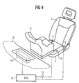
- the locking devices 6 are not shown according to the aforementioned US 5,468,014 Sensors arranged over lines 12 with a control unit 14 (Electronic Control Unit) are connected via the an airbag unit 16 is controlled in the area in front the front passenger seat 2 in the control panel 18 of the motor vehicle is housed.
- the not shown, in the locking devices 6 recorded sensors can, for example, as Pulse generator can be formed, the control unit 14 on impulses generated by them react and trigger the Airbag unit 16 locks.
- the sensors be designed such that they are not properly locked the fastening components 10 with the locking devices 6 send out a signal that shows a warning in the control panel triggers.
- Another way to get an airbag deactivation signal generate consists in the front passenger seat 2 transmission and reception mats accommodate and in the child seat 8 a transponder to accommodate the on a broadcast signal with a response signal responds, which then from the reception mat to the Control unit 14 is transmitted and the airbag is blocked triggers.
- the invention has for its object a generic Continuing to develop occupant protection system in that simple Training against a particularly high level of security Malfunction is achieved.
- the occupant protection system influences the Switching status of the switch the effectiveness of the electrical Functional elements, through which in turn the functionality of the zone circle is so influenceable that the airbag at open switch via the then effective electrical functional element cannot be triggered.
- a control unit 14 is connected via a line 20 a squib 22 connected in the airbag unit 16 4 is arranged.
- the squib 22 is over a Series connection of two switches 26 and 28 with the control unit 14 connected. Are parallel to switches 26 and 28 Resistors 30 and 32.
- the circuit described forms an ignition circuit 40 for igniting the squib 22.
- the control unit 14 connects to signals at its inputs 34 the ignition circuit 40 with a voltage source, not shown, for example an ignition capacitor.
- the signals are, for example generated by delay sensors and in the control unit evaluated.
- the function of the arrangement described is as follows: In the state shown, in which the switches 26 and 28 are closed, the child seat 8 is not fastened to the front passenger seat 2, ie the fastening components 10 do not protrude into the latching devices 6.
- the circuit shown then functions in a manner known per se like a conventional circuit for triggering an airbag, ie when the squib 22 is connected to a corresponding voltage source, not shown, which is contained, for example, in the control unit 14, the squib 22 is supplied with as much power, that pyrotechnic material for inflating the airbag, not shown, is ignited.
- Ignition circuit can be done in a manner known per se from the control unit 14 are constantly recorded for diagnostic purposes, so that from Control unit 14 can be diagnosed with a condition which only one of the switches 26 and 28 is closed. This can be used for an error message displayed to the driver as it indicates a dangerous state in that the child seat 8 is insufficient on the front passenger seat 2 is attached.
- each of the switches has a reed contact 42 on which a permanent magnet 44 is slidably disposed.
- the permanent magnet 44 is against a stop by a spring 46 48 elastic pre-tensioned. In the adjoining stop 48 The position of the permanent magnet 44 is the reed contact 42 closed.
- An actuator 50 that mates with the mounting member 10 (Fig. 1) cooperates, when inserting a fastening component 10 (FIG. 4 or FIG. 1) in the associated locking device 6 (Fig. 1) from the position 2 in the position of FIG. 3 shifted and shifted the permanent magnet 44 against the force of the spring 46 to the left so that the reed contact 42 opens.
- FIGS. 2 and 3 can, for example, within a rotary latch can be arranged within the locking devices 6 is arranged and locks the child seat.
- the invention is particularly well suited for use in modern Child seats, as they are called "Isofix child seat” have become known that are easy to handle and through appropriate mechanical connections with the Passenger seat or locking devices attached to the vehicle can be locked.
- the actuator 50 also formed directly by the fastening component 10 can be and that other switches than working with reed contacts Switches can be used.
- FIGS. 2 and 3 The arrangement of FIGS. 2 and 3 is advantageously such that that the permanent magnet 44 only then in the position shown in FIG. 3rd is moved, in which the reed contact 42 is open, if one Locking device for mechanical locking of the fastening component 10 is engaged in the locking device 6, for example a rotary latch, a locking pin, etc.
- the actuating part 50 is therefore advantageously a locking part actuated. It is understood that the locking device in this case advantageously constructed in this way is that it can only be locked when there is a fastening component is in the locking device and not easy can be moved into a locking position by manipulation.
- the invention can be used wherever triggering of an airbag should be reliably prevented when a fixed object in the vehicle by triggering becomes.
- One or more fastenings can be provided his.
Landscapes
- Engineering & Computer Science (AREA)
- Mechanical Engineering (AREA)
- Health & Medical Sciences (AREA)
- Child & Adolescent Psychology (AREA)
- General Health & Medical Sciences (AREA)
- Aviation & Aerospace Engineering (AREA)
- Transportation (AREA)
- Air Bags (AREA)
- Seats For Vehicles (AREA)
Description
Die Erfindung betrifft ein Insassenschutzsystem mit einem
Kindersitz für ein Kraftfahrzeug gemäß dem Oberbegriff des
Anspruchs 1. Ein derardiges Insassen schutzsystem ist
aus des EP-A-0819566 bekannt.
Im Insassenschutz von Kraftfahrzeugen kommt auch dem Schutz
mitgeführter Kinder, insbesondere Kleinkinder, große Bedeutung
zu. Es wurden Kindersitze entwickelt, die auf dem Beifahrersitz
rückwärts zur Fahrtrichtung befestigt werden können,
so daß sich ein auf dem Kindersitz sitzendes Kind in der
Nähe der das Fahrzeug fahrenden Mutter oder des Vaters befindet,
bei einem Aufprall des Fahrzeugs aber dennoch insbesondere
durch die Rücklehne des Kindersitzes selbst geschützt
ist. Ein Problem, daß sich bei solchen Kindersitzen stellt,
ist, daß ein vor dem Beifahrersitz befindlicher Airbag nicht
ausgelöst werden darf, wenn sich der Kindersitz auf dem Beifahrersitz
befindet. Ein Auslösen des Airbags könnte für das
Kind eine zusätzliche Verletzungsgefahr darstellen.The invention relates to an occupant protection system with a child seat for a motor vehicle according to the preamble of claim 1. Such a occupant protection system is known from EP-A-0819566.
In the protection of occupants of motor vehicles, the protection of accompanying children, in particular small children, is also of great importance. Child seats have been developed that can be attached to the passenger seat backwards to the direction of travel, so that a child sitting on the child seat is close to the mother or father driving the vehicle, but still in a crash of the vehicle, in particular through the backrest of the Child seat itself is protected. One problem that arises with such child seats is that an airbag in front of the front passenger seat must not be deployed when the child seat is in the front passenger seat. An airbag deployment could pose an additional risk of injury to the child.
Zur Lösung dieses Problems wird in der gattungsbildenden US
5,468,014, der die beigefügte Figur 4 weitgehend entnommen
ist, vorgeschlagen, mittels eines Sensors festzustellen, ob
bzw. daß ein Kindersitz an einer verriegelbaren Rasteinrichtung
befestigt ist und bei verriegelter Rasteinrichtung das
Auslösen des den Beifahrersitz zugeordneten Airbags zu deaktivieren.
Gemäß Fig. 4 sind auf einem Beifahrersitz 2 im
rückwärtigsten Bereich von dessen Sitzkissen 4 Rasteinrichtungen
6 zur Aufnahme von an einem Kindersitz 8 ausgebildeten
Befestigungsbauteilen 10 vorgesehen. Es versteht sich, daß
die Rasteinrichtungen 6 starr mit dem Gestell des Beifahrersitzes
2 verbunden sind und die Befestigungsbauteile 10 starr
mit einem Grundgestell des als Sicherheitssitz ausgebildeten
Kindersitzes 8 verbunden sind. In den Rasteinrichtungen 6
sind gemäß der vorgenannten US 5,468,014 nicht dargestellte
Sensoren angeordnet, die über Leitungen 12 mit einem Steuergerät
14 (Electronic Control Unit) verbunden sind, über das
eine Airbag-Einheit 16 angesteuert wird, die im Bereich vor
dem Beifahrersitz 2 in der Schalttafel 18 des Kraftfahrzeugs
untergebracht ist. Die nicht dargestellten, in den Rasteinrichtungen
6 aufgenommenen Sensoren können beispielsweise als
Impulsgeber ausgebildet sein, wobei das Steuergerät 14 auf
von ihnen erzeugte Impulse reagiert und eine Auslösung der
Airbag-Einheit 16 sperrt. Des weiteren können die Sensoren
derart ausgebildet sein, daß sie bei nicht einwandfreier Verrastung
der Befestigungsbauteile 10 mit den Rasteinrichtungen
6 ein Signal aussenden, das in der Schalttafel eine Warnanzeige
auslöst.To solve this problem in the generic US
5,468,014, which is largely taken from the attached FIG. 4
is proposed to determine by means of a sensor whether
or that a child seat on a lockable locking device
is attached and when the locking device is locked
De-activate the airbag assigned to the front passenger seat.
4 are on a
Eine andere Möglichkeit, ein Signal zur Airbag-Abschaltung zu
erzeugen, besteht darin, im Beifahrersitz 2 Sende- und Empfangsmatten
unterzubringen und im Kindersitz 8 einen Transponder
unterzubringen, der auf ein Sendesignal mit einem Antwortsignal
reagiert, das dann von der Empfangsmatte zu dem
Steuergerät 14 übertragen wird und eine Sperrung des Airbags
auslöst.Another way to get an airbag deactivation signal
generate, consists in the
Der Erfindung liegt die Aufgabe zugrunde, ein gattungsgemäßes Insassenschutzsystem dahingehend weiterzubilden, daß bei einfacher Ausbildung ein besonders hohes Maß an Sicherheit gegen Fehlfunktionen erzielt wird.The invention has for its object a generic Continuing to develop occupant protection system in that simple Training against a particularly high level of security Malfunction is achieved.
Diese Aufgabe wird mit den Merkmalen des Hauptanspruchs gelöst.This object is achieved with the features of the main claim.
Bei dem erfindungsgemäßen Insassenschutzsystem beeinflußt der Schaltzustand des Schalters die Wirksamkeit des elektrischen Funktionselements, über das wiederum die Funktionalität des Zond kreises derart beeinflußbar ist, daß der Airbag bei offenem Schalter über das dann wirksame elektrische Funktionselement nicht auslösbar ist. In the occupant protection system according to the invention influences the Switching status of the switch the effectiveness of the electrical Functional elements, through which in turn the functionality of the zone circle is so influenceable that the airbag at open switch via the then effective electrical functional element cannot be triggered.
Die Unteransprüche sind auf vorteilhafte Ausführungsformen und Weiterbildungen des erfindungsgemäßen Insassenschutzsystems gerichtet.The subclaims relate to advantageous embodiments and further developments of the occupant protection system according to the invention directed.
Die Erfindung wird im Folgenden anhand schematischer Zeichnungen beispielsweise und mit weiteren Einzelheiten erläutert.The invention is described below with the aid of schematic drawings for example and explained in more detail.
Es stellen dar:
- Fig. 1
- ein Blockschaltbild eines erfindungsgemäßen Insassenschutzsystems,
- Fig. 2 und 3
- zwei unterschiedliche Stellungen eines Schalters, und
- Fig. 4
- eine Prinzipanordnung eines bekannten Insassenschutzsystems, das weiter oben bereits erläutert wurde.
- Fig. 1
- 2 shows a block diagram of an occupant protection system according to the invention,
- 2 and 3
- two different positions of a switch, and
- Fig. 4
- a basic arrangement of a known occupant protection system, which has already been explained above.
Gemäß Fig. 1 ist ein Steuergerät 14 über eine Leitung 20 mit
einer Zündpille 22 verbunden, die in der Airbag-Einheit 16
gemäß Fig. 4 angeordnet ist. Die Zündpille 22 ist über eine
Reihenschaltung aus zwei Schaltern 26 und 28 mit dem Steuergerat
14 verbunden. Parallel zu den Schaltern 26 und 28 liegen
Widerstände 30 und 32. Der beschriebene Stromkreis bildet
einen Zündkreis 40 zum Zünden der Zündpille 22. Das Steuergerät
14 verbindet auf an seinen Eingängen 34 liegende Signale hin
den Zündkreis 40 mit einer nicht dargestellten Spannungsquelle,
beispielsweise einem Zündkondensator. Die Signale werden beispielsweise
von Verzögerungssensoren erzeugt und im Steuergerät
ausgewertet.1, a
Die Schalter 26 und 28, die innerhalb der Rasteinrichtungen 6
der Fig. 4 angeordnet sind, werden über Stößel 36 und 38 geöffnet,
die von an dem am Kindersitz 8 (Fig. 4) angebrachten
Befestigungsbauteilen 10 bei deren Einschieben in die Rasteinrichtungen
6 betätigt werden.The
Die Funktion der beschriebenen Anordnung ist folgende:
In dem dargestellten Zustand, in dem die Schalter 26 und 28
geschlossen sind, ist der Kindersitz 8 nicht an dem Beifahrersitz
2 befestigt, d.h. ragen die Befestigungsbauteile 10
nicht in die Rasteinrichtungen 6 ein. Die dargestellte Schaltung
funktioniert dann in an sich bekannter Weise wie eine
übliche Schaltung zur Auslösung eines Airbags, d.h. bei Verbinden
der Zündpille 22 mit einer entsprechenden, nicht dargestellten
Spannungsquelle, die beispielsweise in dem Steuergerät
14 enthalten ist, wird der Zündpille 22 soviel Leistung
zugeführt, daß pyrotechnisches Material zum Aufblasen des
nicht dargestellten Airbags gezündet wird.The function of the arrangement described is as follows:
In the state shown, in which the
Wenn der Kindersitz 8 am Beifahrersitz 2 befestigt wird, d.h.
die Befestigungsbauteile 10 in die Rasteinrichtungen 6 eingeschoben
werden, werden die Stößel 36 und 38 betätigt, so daß
die Schalter 26 und 28 öffnen und die Reihenschaltung aus den
Widerständen 30 und 32 wirksam wird. Dadurch vergrößert sich
der Widerstand, über den die Zündpille 22 mit der Zündenergiequelle
verbunden ist, wodurch die der Zündpille 22 zugeführte
Leistung nicht mehr für deren Zündung ausreicht. Es
ist somit ein hohes Maß an Sicherheit gegen Fehlauslösungen
bei am Beifahrersitz 2 angebrachtem Kindersitz 8 geschaffen.
Der Widerstand des in Fig. 1 insgesamt mit 40 bezeichneten
Zündkreises kann in an sich bekannter Weise vom Steuergerät
14 aus zu Diagnosezwecken ständig erfaßt werden, so daß vom
Steuergerät 14 ein Zustand diagnostiziert werden kann, bei
dem nur einer der Schalter 26 und 28 geschlossen ist. Dies
kann für eine dem Fahrer angezeigte Fehlermeldung genutzt
werden, da es auf einen gefährlichen Zustand hindeutet, in
dem der Kindersitz 8 nur unzureichend an dem Beifahrersitz 2
befestigt ist. When the
Mit der dargestellten Schaltung wird somit neben einer Unterbindung der Auslösbarkeit des Airbags auch eine Diagnose der einwandfreien Befestigung des Kindersitzes erzielt.With the circuit shown is thus in addition to a ligation the deployment of the airbag also a diagnosis of achieved perfect attachment of the child seat.
Parallel zu dem Schaltern 26 und 28 müssen nicht zwingend die
als Überbrückungswiderstände mit im dargestellten Beispiel
jeweils etwa 1 kΩ eingezeichneten Widerstände 30 und 32 geschaltet
sein; die Bauteile 30 und 32 könnten auch Induktivitäten
oder Kapazitäten sein, deren von Ausgängen des Steuergeräts
14 her erfaßbare elektrische Wirksamkeit sich mit der
Stellung der Schalter 26 und 28 ändert.In parallel to the
Für die anhand der Fig. 1 geschilderte mehrfache redundante
Funktionssicherheit des Systems ist eine möglichst einfache,
aber dennoch langzeithaltbare und funktionssichere Ausbildung
der Schalter 26 und 28 und deren Zusammenwirken mit den Befestigungsbauteilen
10 vorteilhaft.For the multiple redundant described with reference to FIG. 1
The functional reliability of the system is as simple as possible,
but still long-lasting and reliable training
the
Die Fig. 2 und 3 stellen zwei verschiedene Schaltzustände einer besonders vorteilhaften Ausbildung der Schalter dar.2 and 3 represent two different switching states one particularly advantageous design of the switch.
Gemäß Fig. 2 weist jeder der Schalter einen Reed-Kontakt 42
auf, an dem ein Dauermagnet 44 verschiebbar angeordnet ist.
Der Dauermagnet 44 wird von einer Feder 46 gegen einen Anschlag
48 elastisch vorgespannt. In der am Anschlag 48 anliegenden
Stellung des Dauermagneten 44 ist der Reed-Kontakt 42
geschlossen. Ein Betätigungsteil 50, das mit dem Befestigungsbauteil
10 (Fig. 1) zusammenwirkt, wird bei dem Einschieben
eines Befestigungsbauteils 10 (Fig. 4 oder Fig. 1)
in die zugehörige Rasteinrichtung 6 (Fig. 1) aus der Stellung
gemäß Fig. 2 in die Stellung der Fig. 3 verschoben und verschiebt
dabei den Dauermagnet 44 gegen die Kraft der Feder 46
nach links, so daß der Reed-Kontakt 42 öffnet.2, each of the switches has a
Die Anordnung der Fig. 2 und 3 kann beispielsweise innerhalb
einer Drehfalle angeordnet sein, die innerhalb der Rasteinrichtungen
6 angeordnet ist und den Kindersitz verriegelt.
Die Erfindung eignet sich besonders gut zur Anwendung bei modernen
Kindersitzen, wie sie unter der Bezeichnung "Isofix-Kindersitz"
bekannt geworden sind, die einfach handhabbar und
durch entsprechende mechanische Verbindungen sicher mit dem
Beifahrersitz bzw. am Fahrzeug befestigten Rasteinrichtungen
verrastbar sind. Es versteht sich, daß das Betätigungsteil 50
auch unmittelbar durch das Befestigungsbauteil 10 gebildet
sein kann und daß andere Schalter als mit Reed-Kontakten arbeitende
Schalter verwendet werden können.The arrangement of FIGS. 2 and 3 can, for example, within
a rotary latch can be arranged within the
Vorteilhafterweise ist die Anordnung der Fig. 2 und 3 derart,
daß der Dauermagnet 44 erst dann in die Stellung gemäß Fig. 3
bewegt ist, in der der Reed-Kontakt 42 geöffnet ist, wenn eine
Rasteinrichtung zur mechanischen Verriegelung des Befestigungsbauteils
10 in der Rasteinrichtung 6 eingerastet ist,
beispielsweise eine Drehfalle, ein Riegelzapfen usw. Das Betätigungsteil
50 wird daher vorteilhafterweise von einem Verriegelungsteil
betätigt. Es versteht sich, daß die Rasteinrichtung
in diesem Fall vorteilhafterweise derart aufgebaut
ist, daß sie nur verrastbar ist, wenn sich ein Befestigungsbauteil
in der Rasteinrichtung befindet und nicht einfach
durch Manipulation in eine Riegelstellung bewegbar ist.The arrangement of FIGS. 2 and 3 is advantageously such that
that the
Die Erfindung ist überall dort einsetzbar, wo das Auslösen eines Airbags zuverlässig verhindert werden soll, wenn ein durch das Auslösen gefärdetes Objekt im Fahrzeug befestigt wird. Dabei können eine oder mehrere Befestigungen vorgesehen sein.The invention can be used wherever triggering of an airbag should be reliably prevented when a fixed object in the vehicle by triggering becomes. One or more fastenings can be provided his.
Claims (6)
- Vehicle occupant protection system for a motor vehicle, containing an ignition circuit (40) with an igniter (22) for an airbag unit (16), a control unit (14) for activating the igniter (22),
an interlocking latching mechanism (6) for securing a child seat (8), and
a sensor facility which contains a switch (26, 28), which is open when the latching mechanism (6) is interlocked, and an electrical element (30, 32),
characterised in that
when the latching mechanism is interlocked the sensor facility prevents activation of the igniter (22), whereby the switch (26, 28) and the electrical element (30, 32) are contained parallel to one another in the ignition circuit (40), and that when the switch (26, 28) is open the airbag unit (16) is not capable of being triggered by way of the then changed electrical functionality of the parallel circuit comprising switch (26, 28) and electrical element (30, 32). - Vehicle occupant protection system according to Claim 1, characterised in that the electrical element is a resistor (30, 32).
- Vehicle occupant protection system according to Claim 2, characterised in that the control unit (14) contains a diagnostic function for determining the electrical resistance of the ignition circuit (40).
- Vehicle occupant protection system according to Claim 3, characterised in that two switches (26, 28), each with a respective resistor (30, 32) connected in parallel, are contained in series in the ignition circuit (40).
- Vehicle occupant protection system according to one of Claims 1 to 4,
characterised in that the switch contains a reed contact (42). - Vehicle occupant protection system according to Claim 5, characterised in that the latching mechanism contains a magnet (44) which, when a child seat (8) is fitted, is moved into a position in which the reed contact (48) opens.
Applications Claiming Priority (3)
| Application Number | Priority Date | Filing Date | Title |
|---|---|---|---|
| DE19960248 | 1999-12-14 | ||
| DE19960248 | 1999-12-14 | ||
| PCT/DE2000/004408 WO2001044022A1 (en) | 1999-12-14 | 2000-12-12 | Occupant-protection system for a motor vehicle, comprising a child's seat |
Publications (2)
| Publication Number | Publication Date |
|---|---|
| EP1237756A1 EP1237756A1 (en) | 2002-09-11 |
| EP1237756B1 true EP1237756B1 (en) | 2003-05-02 |
Family
ID=7932608
Family Applications (1)
| Application Number | Title | Priority Date | Filing Date |
|---|---|---|---|
| EP00990523A Expired - Lifetime EP1237756B1 (en) | 1999-12-14 | 2000-12-12 | Occupant-protection system for a motor vehicle, comprising a child's seat |
Country Status (6)
| Country | Link |
|---|---|
| US (1) | US6755437B2 (en) |
| EP (1) | EP1237756B1 (en) |
| JP (1) | JP2003516903A (en) |
| KR (1) | KR100524259B1 (en) |
| DE (1) | DE50002025D1 (en) |
| WO (1) | WO2001044022A1 (en) |
Families Citing this family (19)
| Publication number | Priority date | Publication date | Assignee | Title |
|---|---|---|---|---|
| US7159686B2 (en) * | 2003-09-17 | 2007-01-09 | Delphi Technologies, Inc. | Apparatus and method for detection of a latching device |
| JP4430381B2 (en) * | 2003-11-20 | 2010-03-10 | 本田技研工業株式会社 | Occupant detection device |
| JP4285281B2 (en) * | 2004-03-08 | 2009-06-24 | 株式会社デンソー | Vehicle seat belt warning device |
| DE102004057600A1 (en) * | 2004-11-29 | 2006-06-14 | Bayerische Motoren Werke Ag | Seat occupancy pressure sensor |
| US7201369B2 (en) * | 2004-12-09 | 2007-04-10 | Lockheed Martin Corporation | Vertical justification system |
| GB2424177B (en) * | 2004-12-16 | 2008-03-12 | Nissan Technical Ct Europ Ltd | Vehicle seat assembly |
| EP1683684A1 (en) * | 2005-01-21 | 2006-07-26 | IEE INTERNATIONAL ELECTRONICS & ENGINEERING S.A. | Checkable seat occupancy sensor |
| US7714737B1 (en) | 2006-08-17 | 2010-05-11 | James Morningstar | Warning system for child left unattended in vehicle |
| US8063788B1 (en) | 2006-08-17 | 2011-11-22 | James Morningstar | Unattended child alert system and method |
| KR100787670B1 (en) | 2006-12-07 | 2007-12-21 | 현대자동차주식회사 | Undeveloped airbag according to vehicle seat |
| DE102007022463A1 (en) * | 2007-05-09 | 2008-11-13 | Takata-Petri Ag | measuring system |
| US20100198464A1 (en) * | 2009-01-30 | 2010-08-05 | Delphi Technologies, Inc. | Diagnosable magnetic switch assembly |
| KR100972828B1 (en) * | 2009-12-31 | 2010-07-28 | (주) 골프존 | Virtual golf simulation apparatus and method using a user history information |
| KR101010282B1 (en) * | 2010-03-02 | 2011-01-24 | (주) 골프존 | Apparatus and method for making a user-defined golf course used for the virtual golf simulation, and a virtual golf simulation method using the same |
| FR3063053B1 (en) * | 2017-02-20 | 2019-10-25 | Peugeot Citroen Automobiles Sa | AUTOMOBILE SECURITY DEVICE |
| JP7086192B2 (en) * | 2018-07-20 | 2022-06-17 | アルプスアルパイン株式会社 | Switch circuits, switch devices and systems |
| DE102019202740B4 (en) * | 2019-02-25 | 2022-11-10 | Continental Automotive Technologies GmbH | Circuit arrangement for deactivating an occupant protection device and occupant protection system |
| CN112550093B (en) * | 2019-09-10 | 2023-10-20 | 明门瑞士股份有限公司 | Child safety seats and warning systems |
| CN120663817A (en) * | 2019-09-10 | 2025-09-19 | 宝钜瑞士股份有限公司 | Child safety seat and assembly system reminding device thereof |
Family Cites Families (15)
| Publication number | Priority date | Publication date | Assignee | Title |
|---|---|---|---|---|
| US3745523A (en) * | 1971-10-20 | 1973-07-10 | Allied Chem | Diagnostic system for inflatable safety bag firing circuit |
| US3766612A (en) * | 1972-05-02 | 1973-10-23 | Tokai Rika Co Ltd | Seat belt buckle provided with a switch means |
| JPS5073327A (en) * | 1973-11-06 | 1975-06-17 | ||
| DE4243826A1 (en) | 1992-12-23 | 1994-06-30 | Opel Adam Ag | Motor vehicle with at least one vehicle seat and an associated child seat |
| US5605348A (en) * | 1993-11-03 | 1997-02-25 | Trw Vehicle Safety Systems Inc. | Method and apparatus for sensing a rearward facing child seat |
| US5690356A (en) * | 1995-11-30 | 1997-11-25 | Alliedsignal Inc. | Integrated switch for air bag deactivation |
| EP0791499B1 (en) * | 1996-02-20 | 2004-10-20 | Dr.Ing.h.c. F. Porsche Aktiengesellschaft | Automotive vehicle with at least one passenger seat |
| US6007093A (en) * | 1996-07-17 | 1999-12-28 | Dr.Ing. H.C.F. Porsche Ag | Apparatus and method for deactivating an airbag |
| DE19722734A1 (en) * | 1996-07-17 | 1998-12-03 | Porsche Ag | Motor vehicle with at least one vehicle seat |
| US5851025A (en) * | 1996-12-20 | 1998-12-22 | Gamboa; Martin G. | Air bag deactivation buckle |
| US5882035A (en) * | 1997-08-06 | 1999-03-16 | Munro Associates | Child seat air bag safety system |
| US6145874A (en) * | 1997-10-29 | 2000-11-14 | Trw Inc. | Passenger air bag disable switch |
| DE29903414U1 (en) * | 1998-07-07 | 1999-07-01 | TRW Automotive Electronics & Components GmbH & Co. KG, 78315 Radolfzell | Device for monitoring the locking position of a connecting device, in particular the locking position of a device for fastening a child seat in a vehicle |
| ES2183604T3 (en) * | 1998-07-07 | 2003-03-16 | Trw Automotive Electron & Comp | DEVICE FOR MONITORING THE LOCK POSITION OF A UNION MECHANISM FOR THE SETTING OF A CHILD SEAT. |
| JP3428495B2 (en) * | 1999-05-21 | 2003-07-22 | トヨタ自動車株式会社 | Airbag device operation control system for passenger seat |
-
2000
- 2000-12-12 WO PCT/DE2000/004408 patent/WO2001044022A1/en not_active Ceased
- 2000-12-12 EP EP00990523A patent/EP1237756B1/en not_active Expired - Lifetime
- 2000-12-12 KR KR10-2002-7007380A patent/KR100524259B1/en not_active Expired - Fee Related
- 2000-12-12 JP JP2001545128A patent/JP2003516903A/en active Pending
- 2000-12-12 DE DE50002025T patent/DE50002025D1/en not_active Expired - Lifetime
-
2002
- 2002-06-14 US US10/170,653 patent/US6755437B2/en not_active Expired - Fee Related
Also Published As
| Publication number | Publication date |
|---|---|
| US20020163171A1 (en) | 2002-11-07 |
| KR100524259B1 (en) | 2005-11-01 |
| KR20020065558A (en) | 2002-08-13 |
| JP2003516903A (en) | 2003-05-20 |
| US6755437B2 (en) | 2004-06-29 |
| DE50002025D1 (en) | 2003-06-05 |
| EP1237756A1 (en) | 2002-09-11 |
| WO2001044022A1 (en) | 2001-06-21 |
Similar Documents
| Publication | Publication Date | Title |
|---|---|---|
| EP1237756B1 (en) | Occupant-protection system for a motor vehicle, comprising a child's seat | |
| DE69504291T2 (en) | Control circuit for an airbag opening device. | |
| EP1012008B1 (en) | Device for protecting passengers in a motor vehicle | |
| DE3809074C2 (en) | ||
| DE4016610C2 (en) | ||
| DE69206086T3 (en) | Side impact sensor system for side airbag. | |
| DE69616527T2 (en) | SAFETY DEVICE OF A MOTOR VEHICLE | |
| EP0284770B2 (en) | Control circuit for protection device | |
| DE19547727A1 (en) | Servo-driven door lock for vehicle | |
| DE19724344C2 (en) | Device for identifying the type of occupancy of the passenger seat of a motor vehicle | |
| DE69511550T2 (en) | ARRANGEMENT FOR SWITCHING OFF A VEHICLE AIR BAG | |
| DE19547307B4 (en) | Passenger protection device and associated actuating device | |
| DE602005006028T2 (en) | Mounting anchor for a motor vehicle | |
| EP1089899B1 (en) | Device for triggering a passenger protection device of an automobile | |
| EP0934184B1 (en) | Control arrangement for a passenger-protection system to protect against side impact in a vehicle | |
| EP0755832B1 (en) | System for triggering occupant restraint in a vehicle | |
| DE102012212802B4 (en) | Child seat for a motor vehicle | |
| DE202005014110U1 (en) | Sealing system for vehicle rear seat backrests has catch frame that is attached to framework of backrest | |
| DE4306488A1 (en) | Actuating system for air bags | |
| EP1780075A1 (en) | Crash-active headrest | |
| EP0591669B1 (en) | Method of central vehicle locking with anti-theft function and apparatus for the same | |
| DE19960179A1 (en) | Motor vehicle safety device has switch connected to interact logically with ignition switch or ignition position of ignition lock so deactivation can only take place with ignition lock activated | |
| DE10018194B4 (en) | Safety device on a vehicle door | |
| DE10038427A1 (en) | Safety device for rear passengers in vehicle has switch that interacts with child lock locking element so airbag device is switched off in locking position of the locking element and vice-versa | |
| EP1159162B1 (en) | Arrangement for deactivating a firing device of an airbag |
Legal Events
| Date | Code | Title | Description |
|---|---|---|---|
| PUAI | Public reference made under article 153(3) epc to a published international application that has entered the european phase |
Free format text: ORIGINAL CODE: 0009012 |
|
| 17P | Request for examination filed |
Effective date: 20020429 |
|
| AK | Designated contracting states |
Kind code of ref document: A1 Designated state(s): AT BE CH CY DE DK ES FI FR GB GR IE IT LI LU MC NL PT SE TR |
|
| GRAH | Despatch of communication of intention to grant a patent |
Free format text: ORIGINAL CODE: EPIDOS IGRA |
|
| GRAH | Despatch of communication of intention to grant a patent |
Free format text: ORIGINAL CODE: EPIDOS IGRA |
|
| GRAA | (expected) grant |
Free format text: ORIGINAL CODE: 0009210 |
|
| AK | Designated contracting states |
Designated state(s): DE FR GB IT |
|
| REG | Reference to a national code |
Ref country code: GB Ref legal event code: FG4D Free format text: NOT ENGLISH |
|
| GBT | Gb: translation of ep patent filed (gb section 77(6)(a)/1977) |
Effective date: 20030502 |
|
| REF | Corresponds to: |
Ref document number: 50002025 Country of ref document: DE Date of ref document: 20030605 Kind code of ref document: P |
|
| REG | Reference to a national code |
Ref country code: IE Ref legal event code: FG4D Free format text: GERMAN |
|
| REG | Reference to a national code |
Ref country code: IE Ref legal event code: FD4D Ref document number: 1237756E Country of ref document: IE |
|
| ET | Fr: translation filed | ||
| PLBE | No opposition filed within time limit |
Free format text: ORIGINAL CODE: 0009261 |
|
| STAA | Information on the status of an ep patent application or granted ep patent |
Free format text: STATUS: NO OPPOSITION FILED WITHIN TIME LIMIT |
|
| 26N | No opposition filed |
Effective date: 20040203 |
|
| PGFP | Annual fee paid to national office [announced via postgrant information from national office to epo] |
Ref country code: FR Payment date: 20110104 Year of fee payment: 11 |
|
| PGFP | Annual fee paid to national office [announced via postgrant information from national office to epo] |
Ref country code: GB Payment date: 20101221 Year of fee payment: 11 |
|
| PGFP | Annual fee paid to national office [announced via postgrant information from national office to epo] |
Ref country code: DE Payment date: 20101231 Year of fee payment: 11 Ref country code: IT Payment date: 20101227 Year of fee payment: 11 |
|
| REG | Reference to a national code |
Ref country code: FR Ref legal event code: TP |
|
| REG | Reference to a national code |
Ref country code: GB Ref legal event code: 732E Free format text: REGISTERED BETWEEN 20110825 AND 20110831 |
|
| GBPC | Gb: european patent ceased through non-payment of renewal fee |
Effective date: 20111212 |
|
| REG | Reference to a national code |
Ref country code: FR Ref legal event code: ST Effective date: 20120831 |
|
| PG25 | Lapsed in a contracting state [announced via postgrant information from national office to epo] |
Ref country code: GB Free format text: LAPSE BECAUSE OF NON-PAYMENT OF DUE FEES Effective date: 20111212 |
|
| PG25 | Lapsed in a contracting state [announced via postgrant information from national office to epo] |
Ref country code: IT Free format text: LAPSE BECAUSE OF NON-PAYMENT OF DUE FEES Effective date: 20111212 |
|
| PG25 | Lapsed in a contracting state [announced via postgrant information from national office to epo] |
Ref country code: FR Free format text: LAPSE BECAUSE OF NON-PAYMENT OF DUE FEES Effective date: 20120102 |
|
| REG | Reference to a national code |
Ref country code: DE Ref legal event code: R119 Ref document number: 50002025 Country of ref document: DE Effective date: 20120702 |
|
| PG25 | Lapsed in a contracting state [announced via postgrant information from national office to epo] |
Ref country code: DE Free format text: LAPSE BECAUSE OF NON-PAYMENT OF DUE FEES Effective date: 20130702 |
|
| PG25 | Lapsed in a contracting state [announced via postgrant information from national office to epo] |
Ref country code: DE Free format text: LAPSE BECAUSE OF NON-PAYMENT OF DUE FEES Effective date: 20120702 |