EP1237603B1 - Counting mechanism, and spray dose inhaler with said counting mechanism - Google Patents
Counting mechanism, and spray dose inhaler with said counting mechanism Download PDFInfo
- Publication number
- EP1237603B1 EP1237603B1 EP00978188A EP00978188A EP1237603B1 EP 1237603 B1 EP1237603 B1 EP 1237603B1 EP 00978188 A EP00978188 A EP 00978188A EP 00978188 A EP00978188 A EP 00978188A EP 1237603 B1 EP1237603 B1 EP 1237603B1
- Authority
- EP
- European Patent Office
- Prior art keywords
- counting
- wheel
- cap
- control wheel
- counting mechanism
- Prior art date
- Legal status (The legal status is an assumption and is not a legal conclusion. Google has not performed a legal analysis and makes no representation as to the accuracy of the status listed.)
- Expired - Lifetime
Links
Images


Classifications
-
- G—PHYSICS
- G06—COMPUTING OR CALCULATING; COUNTING
- G06M—COUNTING MECHANISMS; COUNTING OF OBJECTS NOT OTHERWISE PROVIDED FOR
- G06M1/00—Design features of general application
- G06M1/08—Design features of general application for actuating the drive
- G06M1/083—Design features of general application for actuating the drive by mechanical means
-
- A—HUMAN NECESSITIES
- A61—MEDICAL OR VETERINARY SCIENCE; HYGIENE
- A61M—DEVICES FOR INTRODUCING MEDIA INTO, OR ONTO, THE BODY; DEVICES FOR TRANSDUCING BODY MEDIA OR FOR TAKING MEDIA FROM THE BODY; DEVICES FOR PRODUCING OR ENDING SLEEP OR STUPOR
- A61M15/00—Inhalators
- A61M15/0065—Inhalators with dosage or measuring devices
- A61M15/0068—Indicating or counting the number of dispensed doses or of remaining doses
- A61M15/007—Mechanical counters
- A61M15/0071—Mechanical counters having a display or indicator
- A61M15/0075—Mechanical counters having a display or indicator on a disc
-
- G—PHYSICS
- G06—COMPUTING OR CALCULATING; COUNTING
- G06M—COUNTING MECHANISMS; COUNTING OF OBJECTS NOT OTHERWISE PROVIDED FOR
- G06M1/00—Design features of general application
- G06M1/04—Design features of general application for driving the stage of lowest order
- G06M1/045—Design features of general application for driving the stage of lowest order for dial, pointer, or similar type indicating means
-
- A—HUMAN NECESSITIES
- A61—MEDICAL OR VETERINARY SCIENCE; HYGIENE
- A61M—DEVICES FOR INTRODUCING MEDIA INTO, OR ONTO, THE BODY; DEVICES FOR TRANSDUCING BODY MEDIA OR FOR TAKING MEDIA FROM THE BODY; DEVICES FOR PRODUCING OR ENDING SLEEP OR STUPOR
- A61M15/00—Inhalators
- A61M15/009—Inhalators using medicine packages with incorporated spraying means, e.g. aerosol cans
Definitions
- the invention relates to a counting mechanism for counting the number of doses delivered from a container and comprising means for connection to the container, for which the closest prior art is WO-A-8602275.
- the invention also concerns a spray dose inhaler into which a spray container can be introduced and comprising a counting mechanism for counting the number of doses delivered from the spray container.
- spray dose inhalers have been developed which deliver one dose of medication per spray.
- spray dose inhalers which have hitherto been made available is that they do not have means for indicating how many doses remain in the spray container. This means that many spray containers are discarded long before they are empty, and in many cases even when they are only half empty. There is therefore a great need for a counting mechanism in order to be able to monitor the spray consumption in a spray dose inhaler.
- a counting mechanism for a spray dose inhaler must therefore have a structure which does not cause variations in the size of the delivered doses, which does not create spaces where the active substance can accumulate, and which does not in any other way interfere with the function of the inhaler.
- the present invention nevertheless makes available a counting mechanism which is of the type discussed in the introduction and which largely avoids the problems mentioned above.
- An arrangement according to the invention is mainly characterized in that the counting mechanism comprises a cap, a counting wheel, and a control wheel, all of which have a substantially circular shape and are concentric in relation to each other, the cap having an outer surface and an inner surface, and a flange-like cap edge projecting from the periphery of the inner surface, and comprising a gear ring which is arranged inside the flange-like cap edge on the inner surface of the cap, an indicator window in the form of a through-opening in the cap, two concentrically arranged inner flanges which project centrally from the inner surface of the cap and of which a first inner flange is arranged radially inside a second inner flange and projects a distance beyond the second inner flange, and in that the first inner flange has a radially projecting locking tooth, and the counting wheel has an outer surface and an inner surface
- first and second inner flanges of the cap, and the centrally arranged through-holes in the counting wheel and control wheel are substantially circular with a radius corresponding to the radius of the first and second inner flange, respectively, of the cap.
- stop tongues on the counting wheel and control wheel are arranged to spring in the radial direction, as a result of which the stop tongues bear with a certain spring force against the teeth of the gear rings of the counting wheel and cap.
- Radial direction is understood as a radial direction in towards or out from a centre axis running through the counting mechanism.
- the number of doses which the counting mechanism is able to count depends on the clearance between the locking tooth, arranged on the inside of the cap, and the corresponding recess in the control wheel, and also on the number of teeth in the gear rings of the counting wheel and cap.
- the clearance should be about 3° and the number of teeth should be 46.
- the clearance should be 1.5° and the number of teeth should be 82.
- the clearance is calculated by dividing 360° by the number of doses which the counting mechanism is intended to be able to count, after which a whole 1° is added to the result.
- the number of teeth must be evenly divisible by the number of stop tongues, plus one extra tooth.
- a suitable spring member for connecting the rod-shaped pin to the control wheel, and for transferring forces acting on the rod-shaped pin to the control wheel is a flat spring.
- the spring member can be a separately manufactured component, but it is advantageously made integral with the rod-shaped pin and the control wheel, for example by injection-moulding of plastic.
- a spray dose inhaler according to the invention is characterized mainly in that the counting mechanism is arranged substantially on the outside of the inhaler and comprises a cap, a counting wheel, and a control wheel, all of which have a substantially circular shape and are concentric in relation to each other, the cap having an outer surface and an inner surface, and a flange-like cap edge projecting from the periphery of the inner surface, and comprising a gear ring which is arranged inside the flange-like cap edge on the inner surface of the cap, an indicator window in the form of a through-opening in the cap, two concentrically arranged inner flanges which project centrally from the inner surface of the cap and of which a first inner flange is arranged radially inside a second inner flange and projects a distance beyond the second inner flange, and in that the first inner flange has a radially projecting locking tooth, and the counting wheel has an outer surface
- the counting mechanism allows the counting mechanism to be arranged almost entirely on the outside of the inhaler, with only the very small rod-shaped pin situated inside the inhaler, the counting mechanism by and large does not in any way affect the flow through the inhaler. This means that the doses delivered retain a constant size, and that the risk of active substance accumulating in the inhaler as a result of the action of the counting mechanism is practically nonexistent.
- the dose scale arranged on the counting wheel is placed in an annular configuration on the outside of the counting wheel and is either ascending or descending, depending on whether the counting mechanism is to indicate how many doses have been administered or how many doses remain.
- the dose scale is preferably a numerical scale, with the dose number being indicated in steps of 1, 2, 5, 10, 25 doses or in other dose steps if deemed appropriate. Alternatively, or in addition to this, it is however possible to imagine using a colour scale, for example ranging from green through yellow to red. For example, the last 10% of the doses can be indicated by red or another differing colour.
- the indicator window is preferably provided with an arrow which points to the dose number in each position.
- the counting mechanism can be provided with a built-in stop position. Such a counting mechanism is discarded when it has counted the predetermined number of doses for which it has been designed. It is also possible to produce re-usable counting mechanisms without built-in stop devices. Such a stop device can be provided, for example, by arranging a pin on the inside of the cap, which pin runs in a groove in the counting wheel.
- Figure 1 shows a spray dose inhaler 1 which is provided with a counting mechanism 2 arranged substantially on the outside of the inhaler.
- the spray dose inhaler 1 has an upper tubular part 3 into which a spray container 4 is introduced.
- the spray dose inhaler 1 also has a lower tubular mouthpiece part 5 which is angled in relation to the upper part 3 and which emerges via an opening 6 from which the contents of the spray container 4 are delivered.
- the mouthpiece part 5 is placed in the user's mouth and the spray container 4 is pressed further down in the upper part 3 of the inhaler 1. A dose is thereby released and is sprayed into the user's oral cavity.
- the counting mechanism 2 consists of three main components, namely a cap 7, a counting wheel 8, and a control wheel 9. Arranged on the outside is the substantially circular cap 7, the latter thus serving as an outer casing for the counting mechanism 2.
- the cap 7 is provided with an indicator window 10, and on the inside of the cap 7 there is a gear ring 11 in which the number of teeth 12 is adapted to the number of doses in the spray container.
- FIG. 2a shows the outside of the cap 7, i.e. the side directed away from the inhaler when the counting mechanism is fitted on an inhaler
- Figure 2b shows the inside of the cap, i.e. the side directed towards the inhaler when the counting mechanism 2 is fitted.
- the teeth 12 are inclined and slope in a first tangential direction.
- the teeth 12 are shown with an inclination anti-clockwise in the figure.
- the cap 7 is additionally provided with a coupling arrangement comprising several parts and intended to cooperate with a corresponding coupling arrangement on the inhaler 1.
- the coupling arrangement on the inhaler 1 is shown in detail in Figure 6 and will be described in detail in the description of Figure 6.
- the coupling arrangement on the cap 7 comprises, on the one hand, a cap edge 13 projecting at right angles from the plane of the cap 7 and an almost rectangular pin 14 projecting from the cap edge 13, and, on the other hand, a centrally arranged cylindrical first inner flange 15. Moreover, the cylindrical inner flange 15 has a locking tooth 16 projecting radially from the outer surface of the inner flange 15.
- annular second inner flange 17 Arranged concentrically to the outside of the cylindrical inner flange 15 there is an annular second inner flange 17 which has less height above the inner surface of the cap than does the cylindrical first inner flange 15, and which is intended to serve as coupling member between the cap 7 and the counting wheel 8.
- the cylindrical first inner flange 15 here fulfills the additional purpose of being a coupling member between the cap 7 and the control wheel 9.
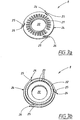
- a counting wheel 8 Arranged inside of the cap 7. or outer casing, there is a counting wheel 8 of the type shown in Figures 3a and 3b.
- the counting wheel 8 has a substantially circular shape, with a central and circular through-hole 20.
- the counting wheel 8 in Figure 3a is shown from the outside, which is the side directed outwards and away from the inhaler 1
- Figure 3b shows the inside, which is the side of the counting wheel 8 directed inwards and towards the inhaler 1.
- the outside of the counting wheel 8 is provided with a numerical scale 21 which is intended to continuously indicate the number of doses remaining in the spray container 4. In the illustrative embodiment shown, the doses are indicated in intervals of 5.
- the counting wheel 8 is either numbered in ascending sequence, so that the number of doses used is indicated, or in descending sequence, so that the number of doses remaining is indicated.
- the numerical scale 21 is visible through the indicator window 10 on the cap.
- the indicator window 10 can be provided with an indicator arrow 19 which points to the current number of doses.
- the last doses for example the last 10% of the doses, are marked in a different way, preferably with a different colour such as red.
- a gear ring 22 is arranged on the inside of the counting wheel 8, about its periphery.
- the number of teeth 23 is adapted to the number of doses which are to be counted, and the teeth 23 are oriented in the opposite direction in relation to the teeth 12 on the cap 7, which means that the teeth 23 in Figure 3b slope clockwise.
- the counting wheel 8 is provided with three stop tongues 25 arranged symmetrically about the outer edge 24 of the counting wheel 8.
- the stop tongues 25 are designed in such a way that they have a certain spring capacity, upon radial loading, in towards or out from the centre of the counting wheel 8.
- the stop tongues 25 have a free pin-shaped part which is directed along the periphery of the counting wheel 8 and which ends in a stop edge 26.
- the free parts of the stop tongues 25, as can be seen from Figure 3b, are directed clockwise about the periphery of the counting wheel 8.
- the stop tongues 25 thus have the same direction as the teeth 23 of the counting wheel 8.
- the third part of the counting mechanism 2 is the control wheel 9 shown in Figures 4a and 4b.
- the control wheel 9 is also substantially circular in shape and is provided with three resilient stop tongues 30 which are distributed symmetrically about the periphery of the wheel 9 and have a free part which springs radially and ends in a stop edge 31.
- the stop tongues 30 of the control wheel 9 are directed in the opposite direction in relation to the stop tongues 25 of the counting wheel 8.
- the control wheel 9 has a rod-shaped pin 32 which is arranged at right angles to the inside of the control wheel 9, which is the side of the control wheel 9 intended to be directed towards the inhaler 1.
- the pin 32 is connected to the control wheel 9 via a flat spring member 33.
- a circular hole 34 is arranged centrally through the control wheel 9 and has a recess 35 arranged on the periphery of the hole 34, which recess 35 has a shape corresponding substantially to the shape of the locking tooth 16 arranged on the cap 7.
- the locking tooth 16 is in fact intended to be introduced into the recess 35 of the control wheel 9, in the manner of a key in a lock.
- Figure 5 shows how the different parts are joined together to form a complete inhaler 1 with counting mechanism 2 and spray container 4.
- the spray container 4 is introduced into the upper tubular part 3 of the spray dose inhaler 1, and the counting mechanism 2 is fitted on the outside of the upper tubular part 3 of the spray dose inhaler 1, near the transition to the mouthpiece part 5.
- FIG. 6 shows in detail the appearance of the coupling arrangement provided on the spray dose inhaler 1.
- the coupling arrangement comprises a circular outer flange 40, which projects from the surface of the inhaler 1 and which has an outer ring 41 and also an inner ring 42 which projects farther than the outer ring 41 and has an external radius corresponding to the internal radius of the projecting cap edge 13 on the cap 7 of the counting mechanism 2.
- a recess 43 is also provided in the outer ring 41 for cooperation with the substantially rectangular pin 14 arranged on the cap edge 13.
- the counting mechanism 2 is fitted with the cap 7 tight over the outer ring 41 of the coupling arrangement of the spray dose inhaler 1, and with the pin 14 on the cap edge 13 inserted into the recess 43 on the outer ring 41 of the coupling arrangement.
- the spray dose inhaler 1 also has a centrally arranged annular inner flange 45 whose internal diameter corresponds to the external diameter of the cylindrical first inner flange 15 on the counting mechanism cap 7.
- the annular inner flange 45 arranged on the spray dose inhaler 1 has a gap 46 through which the locking tooth 16 arranged on the cylindrical first inner flange 15 of the counting mechanism cap 7 can project.
- the spray dose inhaler 1 finally has a through-hole 47 arranged between the inner flange 45 and outer flange 40 of the coupling arrangement.
- the through-hole 47 is designed such that the rod-shaped pin 32 arranged on the control wheel 9 can be introduced through the wall of the spray dose. inhaler 1 and into the inside of the spray dose inhaler.
- the hole has a diameter which is substantially the same as the diameter of the rod-shaped pin 32.
- Figure 7 shows how the spray dose inhaler 1 looks when the counting mechanism 2 has been fitted and the spray container 4 has been introduced into the upper tubular part 3 of the inhaler 1.
- the rod-shaped pin 32 of the control wheel 9 is introduced through the hole 47 in the inhaler wall, and the hole 47 is positioned in such a way that the pin 32 is thereby in contact with the spray container 4 in such a way that, when the spray container 4 is pressed into the inhaler 1, the spray container 4 presses the pin 32 in its direction of movement. In so doing, that part of the pin 32 located inside the inhaler 1 is deflected and/or angled in the downward direction in Figure 7.
- one of the three stop tongues 30 arranged on the control wheel is additionally moved to a new position between two teeth 23 of the counting wheel 8.
- the pin 32 returns to the substantially horizontal position shown in Figure 7 and the control wheel 9 springs back to its initial position, which corresponds to the control wheel 9 rotating anti-clockwise as far as is permitted by the clearance between the locking tooth 16 of the cap 7 and the corresponding recess 35 on the control wheel 9.
- one of the stop tongues 30 of the control wheel 9 rests with its outer stop edge 31 against a tooth 23 of the counting wheel 8.
- the position of the rod-shaped pin 32 is such that the control wheel 9 rotates clockwise when the spray container 4 is pressed into the inhaler 1 upon administration of a spray dose.
- this is not a necessary condition for the invention. It is therefore possible to envisage the pin 32 being positioned instead on the diametrically opposite side of the control wheel 9. Such positioning would mean that the control wheel 9 first rotated anti-clockwise when the spray container 4 was pressed into the inhaler 1.
- such an arrangement would additionally mean that the direction of rotation, like the direction of the different gear rings 11, 22 and stop tongues 25, 30, would be opposite to those directions described above.
- a counting mechanism 2 according to the invention can advantageously be produced by injection moulding of plastic. It is of course also possible to envisage combinations of plastic components and other materials, or counting mechanisms made completely or partially of metal.
- the counting mechanism has been described in association with a spray dose inhaler, it is of course possible to use the counting mechanism in all contexts where a substance is to be sprayed in doses.
- the counting mechanism can be used for spraying cosmetics or the like.
- spray dose inhalers in which the dosed substance is administered into the nose are of course also intended to come within the scope of the invention as defined by the appended claims.
Landscapes
- Health & Medical Sciences (AREA)
- Engineering & Computer Science (AREA)
- Life Sciences & Earth Sciences (AREA)
- Anesthesiology (AREA)
- Bioinformatics & Cheminformatics (AREA)
- Pulmonology (AREA)
- Biophysics (AREA)
- Biomedical Technology (AREA)
- Heart & Thoracic Surgery (AREA)
- Hematology (AREA)
- Animal Behavior & Ethology (AREA)
- General Health & Medical Sciences (AREA)
- Public Health (AREA)
- Veterinary Medicine (AREA)
- Physics & Mathematics (AREA)
- Theoretical Computer Science (AREA)
- General Physics & Mathematics (AREA)
- Containers And Packaging Bodies Having A Special Means To Remove Contents (AREA)
- Fertilizing (AREA)
- Nozzles (AREA)
- Investigating Or Analysing Biological Materials (AREA)
- Acyclic And Carbocyclic Compounds In Medicinal Compositions (AREA)
- Special Spraying Apparatus (AREA)
- Medical Preparation Storing Or Oral Administration Devices (AREA)
- Medicines That Contain Protein Lipid Enzymes And Other Medicines (AREA)
- Pharmaceuticals Containing Other Organic And Inorganic Compounds (AREA)
- External Artificial Organs (AREA)
- Measurement Of Radiation (AREA)
Abstract
Description
Claims (7)
- Counting mechanism (2) for counting the number of doses delivered from a container (4) and comprising means for connection to the container (4), characterized in that the counting mechanism (2) comprises a cap (7), a counting wheel (8), and a control wheel (9), all of which have a substantially circular shape and are concentric in relation to each other, the cap (7) having an outer surface and an inner surface, and a flange-like cap edge (13) projecting from the periphery of the inner surface, and comprising a gear ring (11) which is arranged inside the flange-like cap edge (13) on the inner surface of the cap (7), an indicator window (10) in the form of a through- opening in the cap (7), two concentrically arranged inner flanges (15, 17) which project centrally from the inner surface of the cap (7) and of which a first inner flange (15) is arranged radially inside a second inner flange (17) and projects a distance beyond the second inner flange (17), and in that the first inner flange (15) has a radially projecting locking tooth (16), and the counting wheel (8) has an outer surface and an inner surface and is arranged directly next to the cap (7) with the outer surface of the counting wheel (8) directed towards the inner surface of the cap (7), the counting wheel (8) comprising a centrally arranged through-hole (20) with a shape and size corresponding to the shape and size of the second inner flange (17) of the cap (7), at least one stop tongue (25) which projects from the periphery of the counting wheel and is arranged to engage in and cooperate with the gear ring (11) arranged on the inner surface of the cap (7), and a gear ring (22) arranged on the inner surface of the counting wheel (8), near the periphery of the counting wheel (8), and a measurement scale (21) arranged on the outer surface and placed so that it is visible through the indicator window (10), and in that the control wheel (9) has an outer surface and an inner surface and is arranged directly next to the counting wheel (8), with the outer surface of the control wheel (9) directed towards the inner surface of the counting wheel (8), the control wheel (9) comprising a centrally arranged through-hole (34) with a shape and size corresponding to the shape and size of the first inner flange (15) of the cap (7) and having a recess (35) arranged on the periphery of the hole (34), which recess (35) has a shape which substantially corresponds to the shape of the locking tooth (16) arranged on the cap (7) and with a size which slightly exceeds the size of the locking tooth (16), so that a predetermined clearance exists between the locking tooth (16) and the edges of the recess (35), at least one stop tongue (30) which projects from the periphery of the control wheel (9) and which is arranged to engage in and cooperate with the gear ring (22) arranged on the inner surface of the counting wheel (8), and a rod-shaped pin (32) which is arranged at right angles to the inner surface of the control wheel (9) and is connected to the control wheel (9) via a spring member (33), and in that the stop tongue (30) of the control wheel (9) is oriented in a tangential direction which is opposite to the direction of the gear ring (22) and stop tongue (25) of the counting wheel (8), and in that the direction of the teeth (12) in the gear ring (11) of the cap (7) coincides with the tangential direction of the stop tongue (30) of the control wheel (9), and furthermore in that the number of stop tongues (25, 30) and the number of teeth (12, 23) are identical for the counting wheel (8) and for the control wheel (9).
- Counting mechanism according to Claim 1, characterized in that the number of stop tongues (25, 30) on the periphery of the counting wheel (8) and of the control wheel (9) is a prime number, and in that the stop tongues (25, 30) are symmetrically distributed about the periphery of the respective wheel (8, 9).
- Counting mechanism according to Claim 1 or 2, characterized in that the first and second inner flange (15, 17) of the cap (7), and the centrally arranged through-holes (20, 34) in the counting wheel (8) and the control wheel (9), are substantially circular with a radius corresponding with the radius of the first and second inner flange (15, 17), respectively, of the cap (7).
- Counting mechanism according to Claim 1, 2 or 3, characterized in that the stop tongues (25, 30) on the counting wheel (8) and the control wheel (9) are arranged to spring in the radial direction.
- Counting mechanism according to any of Claims 1 to 4, characterized in that the number of teeth (12, 23) on the counting wheel (8) and the control wheel (9) is 46, and in that the number of stop tongues (25, 30) on the counting wheel (8) and the control wheel (9) is 3, and in that the clearance between the locking tooth (16) and the recess (35) is approximately 3°.
- Counting mechanism according to Claim 1, characterized in that the spring member (33) is a flat spring.
- Spray dose inhaler (1) with an inside and an outside, comprising a first tubular part (3) into which a spray container (4) can be introduced, a second tubular mouthpiece part (5) which is angled in relation to the first part (3) and which emerges into an opening (6) from which the contents of the spray container (4) can be delivered, and comprising a counting mechanism (2), according to claim 1 arranged substantially on the outside of the inhaler (1), where in the outside of the spray dose inhaler (1) is provided with coupling members (40, 43, 45, 47) for connecting the counting mechanism (2) to the spray dose inhaler (1), the coupling members comprising a through-hole (47) through which the rod-shaped pin (32) of the counting mechanism (2) can be introduced, the hole (47) being positioned so that the rod-shaped pin (32) is in contact with the spray container and is acted upon and deflected and/or changes position when the spray container (4) moves in the first part (3) of the spray dose inhaler (1).
Priority Applications (1)
| Application Number | Priority Date | Filing Date | Title |
|---|---|---|---|
| SI200030549T SI1237603T1 (en) | 1999-11-26 | 2000-11-24 | Counting mechanism, and spray dose inhaler with said counting mechanism |
Applications Claiming Priority (3)
| Application Number | Priority Date | Filing Date | Title |
|---|---|---|---|
| SE9904278 | 1999-11-26 | ||
| SE9904278A SE515858C2 (en) | 1999-11-26 | 1999-11-26 | Counter and spray dose inhaler with the counter |
| PCT/SE2000/002319 WO2001037909A1 (en) | 1999-11-26 | 2000-11-24 | Counting mechanism, and spray dose inhaler with said counting mechanism |
Publications (2)
| Publication Number | Publication Date |
|---|---|
| EP1237603A1 EP1237603A1 (en) | 2002-09-11 |
| EP1237603B1 true EP1237603B1 (en) | 2004-09-01 |
Family
ID=20417859
Family Applications (1)
| Application Number | Title | Priority Date | Filing Date |
|---|---|---|---|
| EP00978188A Expired - Lifetime EP1237603B1 (en) | 1999-11-26 | 2000-11-24 | Counting mechanism, and spray dose inhaler with said counting mechanism |
Country Status (10)
| Country | Link |
|---|---|
| EP (1) | EP1237603B1 (en) |
| AT (1) | ATE274947T1 (en) |
| AU (1) | AU1567201A (en) |
| DE (1) | DE60013480T2 (en) |
| DK (1) | DK1237603T3 (en) |
| ES (1) | ES2228631T3 (en) |
| PT (1) | PT1237603E (en) |
| SE (1) | SE515858C2 (en) |
| SI (1) | SI1237603T1 (en) |
| WO (1) | WO2001037909A1 (en) |
Cited By (1)
| Publication number | Priority date | Publication date | Assignee | Title |
|---|---|---|---|---|
| WO2007077450A3 (en) * | 2006-01-04 | 2007-08-30 | 42 Technology Ltd | Dose counter with an odometer type display |
Families Citing this family (38)
| Publication number | Priority date | Publication date | Assignee | Title |
|---|---|---|---|---|
| EP1047467B1 (en) | 1998-01-16 | 2004-06-23 | 1263152 Ontario Inc. | Indicating device for use with a dispensing device |
| US6082358A (en) | 1998-05-05 | 2000-07-04 | 1263152 Ontario Inc. | Indicating device for aerosol container |
| GB2364649A (en) | 2000-05-17 | 2002-02-06 | Orion Corp | Inhaler with Dose Counter |
| FR2830527B1 (en) * | 2001-10-04 | 2004-08-27 | Valois Sa | DOSAGE COUNTER FOR A FLUID PRODUCT DISPENSER |
| US7004164B2 (en) | 2002-03-21 | 2006-02-28 | Trudell Medical International | Indicating device for aerosol container |
| AU2002953483A0 (en) | 2002-12-20 | 2003-01-09 | Acrux Dds Pty. Ltd. | Usage indicator |
| FR2850192B1 (en) | 2003-01-20 | 2005-05-06 | Tebro | DOSING INDICATOR FOR FLUID PRODUCT DISPENSING DEVICE. |
| FR2854878B1 (en) | 2003-05-15 | 2006-03-31 | Valois Sas | FLUID PRODUCT DISPENSER. |
| FR2857769B1 (en) | 2003-07-18 | 2005-10-21 | Valois Sa | IMPROVED DOSAGE INDICATOR FOR FLUID PRODUCT DISPENSING DEVICE. |
| FR2857770B1 (en) * | 2003-07-18 | 2005-10-21 | Valois Sas | IMPROVED DOSAGE INDICATOR FOR FLUID PRODUCT DISPENSING DEVICE. |
| US7621273B2 (en) | 2003-10-28 | 2009-11-24 | Trudell Medical International | Indicating device with warning dosage indicator |
| GB0328859D0 (en) * | 2003-12-12 | 2004-01-14 | Clinical Designs Ltd | Dispenser and counter |
| US7100530B2 (en) | 2003-12-15 | 2006-09-05 | Trudell Medical International, Inc. | Dose indicating device |
| KR101105909B1 (en) | 2004-02-16 | 2012-01-17 | 글락소 그룹 리미티드 | Counter for use with a medicament dispenser |
| FR2873808B1 (en) * | 2004-07-30 | 2006-12-08 | Valois Sa Sa | INDICATOR FOR DEVICE FOR DISPENSING FLUID OR PULVERULENT PRODUCT. |
| FR2869685B1 (en) * | 2004-04-29 | 2006-07-28 | Valois Sas | INDICATOR FOR DEVICE FOR DISPENSING FLUID OR PULVERULENT PRODUCT |
| WO2005114563A1 (en) * | 2004-04-29 | 2005-12-01 | Valois Sas | Indicator for a device for dispensing a liquid or powdery product |
| SE0401773D0 (en) * | 2004-07-02 | 2004-07-02 | Astrazeneca Ab | An inhalation and a method for assessing said inhalation device |
| SE0401786D0 (en) | 2004-07-05 | 2004-07-05 | Astrazeneca Ab | Inhaler device |
| WO2006027333A1 (en) * | 2004-09-04 | 2006-03-16 | Alfred Von Schuckmann | Inhaler device |
| US7543582B2 (en) | 2004-09-20 | 2009-06-09 | Trudell Medical International | Dose indicating device with display elements attached to container |
| GB0425518D0 (en) | 2004-11-19 | 2004-12-22 | Clinical Designs Ltd | Substance source |
| WO2006062448A1 (en) * | 2004-12-10 | 2006-06-15 | Ernst Hörlins Ingenjörsbyrå Ab | Dose inhaler with a dose counter |
| WO2006062450A1 (en) * | 2004-12-10 | 2006-06-15 | Ernst Hörlins Ingenjösbyra Ab | Dose indicator for a dose inhaler |
| CN101810901B (en) | 2005-01-20 | 2013-07-24 | 特鲁德尔医学国际公司 | Dispensing device |
| GB0605150D0 (en) | 2006-03-14 | 2006-04-26 | Glaxo Group Ltd | Counter For Use With A Medicament Dispenser |
| WO2007124406A2 (en) | 2006-04-21 | 2007-11-01 | 3M Innovative Properties Company | Dose counter |
| DE102006031626B3 (en) * | 2006-07-06 | 2008-01-24 | Santo, Wilfried | Mechanical setting or dosing button |
| US8141550B2 (en) | 2006-08-01 | 2012-03-27 | Trudell Medical International | Dispensing device |
| US8082873B2 (en) | 2008-05-05 | 2011-12-27 | Trudell Medical International | Drive mechanism for an indicating device |
| US8181591B1 (en) | 2008-05-23 | 2012-05-22 | Trudell Medical International | Domed actuator for indicating device |
| CA2683353C (en) | 2008-10-22 | 2015-12-15 | Trudell Medical International | Modular aerosol delivery system |
| GB0904059D0 (en) | 2009-03-10 | 2009-04-22 | Euro Celtique Sa | Counter |
| GB0904040D0 (en) | 2009-03-10 | 2009-04-22 | Euro Celtique Sa | Counter |
| WO2013045996A1 (en) | 2011-09-26 | 2013-04-04 | Trudell Medical International | Dose counter and medication delivery device |
| GB2502791B (en) * | 2012-06-06 | 2014-08-20 | Consort Medical Plc | Dose indicator device |
| DE102013214601B3 (en) * | 2013-07-25 | 2014-05-22 | Aptar Radolfzell Gmbh | Housing for container unit of inhalation device e.g. metered-dose inhaler, for oral administration of pharmaceutical medium, has membrane reversibly deformed based on pressure in pressure chamber and acting together with pushbutton |
| CN104984445A (en) * | 2015-07-30 | 2015-10-21 | 中山市美捷时包装制品有限公司 | A dosing actuator device with reverse spray assembly |
Family Cites Families (2)
| Publication number | Priority date | Publication date | Assignee | Title |
|---|---|---|---|---|
| DK481884D0 (en) * | 1984-10-09 | 1984-10-09 | Karl Holm | MEDICAL ORAL OR SWALLOW SPRAY APPLIANCES |
| DE19549033C1 (en) * | 1995-12-28 | 1997-05-28 | Boehringer Ingelheim Int | Mechanical counter for a dosing device |
-
1999
- 1999-11-26 SE SE9904278A patent/SE515858C2/en not_active IP Right Cessation
-
2000
- 2000-11-24 ES ES00978188T patent/ES2228631T3/en not_active Expired - Lifetime
- 2000-11-24 DK DK00978188T patent/DK1237603T3/en active
- 2000-11-24 AU AU15672/01A patent/AU1567201A/en not_active Abandoned
- 2000-11-24 AT AT00978188T patent/ATE274947T1/en not_active IP Right Cessation
- 2000-11-24 DE DE60013480T patent/DE60013480T2/en not_active Expired - Fee Related
- 2000-11-24 EP EP00978188A patent/EP1237603B1/en not_active Expired - Lifetime
- 2000-11-24 SI SI200030549T patent/SI1237603T1/en unknown
- 2000-11-24 PT PT00978188T patent/PT1237603E/en unknown
- 2000-11-24 WO PCT/SE2000/002319 patent/WO2001037909A1/en not_active Ceased
Cited By (1)
| Publication number | Priority date | Publication date | Assignee | Title |
|---|---|---|---|---|
| WO2007077450A3 (en) * | 2006-01-04 | 2007-08-30 | 42 Technology Ltd | Dose counter with an odometer type display |
Also Published As
| Publication number | Publication date |
|---|---|
| AU1567201A (en) | 2001-06-04 |
| SE515858C2 (en) | 2001-10-22 |
| DK1237603T3 (en) | 2005-01-10 |
| PT1237603E (en) | 2004-12-31 |
| DE60013480T2 (en) | 2005-09-15 |
| SE9904278D0 (en) | 1999-11-26 |
| ATE274947T1 (en) | 2004-09-15 |
| SE9904278L (en) | 2001-05-27 |
| SI1237603T1 (en) | 2005-04-30 |
| ES2228631T3 (en) | 2005-04-16 |
| WO2001037909A1 (en) | 2001-05-31 |
| EP1237603A1 (en) | 2002-09-11 |
| DE60013480D1 (en) | 2004-10-07 |
Similar Documents
| Publication | Publication Date | Title |
|---|---|---|
| EP1237603B1 (en) | Counting mechanism, and spray dose inhaler with said counting mechanism | |
| CA2408540C (en) | Inhaler with a dose counter | |
| EP1449557B1 (en) | Dispensing device kit | |
| EP1362326B1 (en) | Dosage counting devices | |
| US7195134B2 (en) | Dosage counting devices | |
| US6502717B1 (en) | Child resistant pill dispensing package | |
| WO2004089451A1 (en) | Counter for counting doses | |
| FI91567B (en) | Shutter calculator | |
| US20020166791A1 (en) | Rotatable compact case with non-removable pill package insert | |
| JPS62502451A (en) | Indicator device for drug dispensing device | |
| IL120246A (en) | Powdered medication inhaler | |
| US7819285B2 (en) | Counter mechanism of feeding device and feeding device using such counter mechanism | |
| CN222258386U (en) | Measuring cylinder for accurately measuring capsule powder for paediatrics | |
| TW202026214A (en) | Tablet dispenser with dosing aid | |
| MXPA00010887A (en) | Indicating device for aerosol container |
Legal Events
| Date | Code | Title | Description |
|---|---|---|---|
| PUAI | Public reference made under article 153(3) epc to a published international application that has entered the european phase |
Free format text: ORIGINAL CODE: 0009012 |
|
| 17P | Request for examination filed |
Effective date: 20020626 |
|
| AK | Designated contracting states |
Kind code of ref document: A1 Designated state(s): AT BE CH CY DE DK ES FI FR GB GR IE IT LI LU MC NL PT SE TR |
|
| AX | Request for extension of the european patent |
Free format text: AL PAYMENT 20020626;LT PAYMENT 20020626;LV PAYMENT 20020626;MK PAYMENT 20020626;RO PAYMENT 20020626;SI PAYMENT 20020626 |
|
| GRAP | Despatch of communication of intention to grant a patent |
Free format text: ORIGINAL CODE: EPIDOSNIGR1 |
|
| GRAS | Grant fee paid |
Free format text: ORIGINAL CODE: EPIDOSNIGR3 |
|
| GRAA | (expected) grant |
Free format text: ORIGINAL CODE: 0009210 |
|
| AK | Designated contracting states |
Kind code of ref document: B1 Designated state(s): AT BE CH CY DE DK ES FI FR GB GR IE IT LI LU MC NL PT SE TR |
|
| AX | Request for extension of the european patent |
Extension state: AL LT LV MK RO SI |
|
| REG | Reference to a national code |
Ref country code: GB Ref legal event code: FG4D |
|
| REG | Reference to a national code |
Ref country code: CH Ref legal event code: EP |
|
| REG | Reference to a national code |
Ref country code: IE Ref legal event code: FG4D |
|
| REF | Corresponds to: |
Ref document number: 60013480 Country of ref document: DE Date of ref document: 20041007 Kind code of ref document: P |
|
| REG | Reference to a national code |
Ref country code: CH Ref legal event code: NV Representative=s name: HEPP, WENGER & RYFFEL AG |
|
| REG | Reference to a national code |
Ref country code: GR Ref legal event code: EP Ref document number: 20040403829 Country of ref document: GR |
|
| REG | Reference to a national code |
Ref country code: SE Ref legal event code: TRGR |
|
| REG | Reference to a national code |
Ref country code: PT Ref legal event code: SC4A Free format text: AVAILABILITY OF NATIONAL TRANSLATION Effective date: 20041029 |
|
| REG | Reference to a national code |
Ref country code: ES Ref legal event code: FG2A Ref document number: 2228631 Country of ref document: ES Kind code of ref document: T3 |
|
| PLBE | No opposition filed within time limit |
Free format text: ORIGINAL CODE: 0009261 |
|
| STAA | Information on the status of an ep patent application or granted ep patent |
Free format text: STATUS: NO OPPOSITION FILED WITHIN TIME LIMIT |
|
| ET | Fr: translation filed | ||
| 26N | No opposition filed |
Effective date: 20050602 |
|
| PGFP | Annual fee paid to national office [announced via postgrant information from national office to epo] |
Ref country code: DK Payment date: 20081008 Year of fee payment: 9 Ref country code: LU Payment date: 20081021 Year of fee payment: 9 Ref country code: NL Payment date: 20081015 Year of fee payment: 9 |
|
| PGFP | Annual fee paid to national office [announced via postgrant information from national office to epo] |
Ref country code: AT Payment date: 20081008 Year of fee payment: 9 Ref country code: ES Payment date: 20081118 Year of fee payment: 9 |
|
| PGFP | Annual fee paid to national office [announced via postgrant information from national office to epo] |
Ref country code: IT Payment date: 20081124 Year of fee payment: 9 Ref country code: SE Payment date: 20081107 Year of fee payment: 9 Ref country code: BE Payment date: 20081128 Year of fee payment: 9 |
|
| PGFP | Annual fee paid to national office [announced via postgrant information from national office to epo] |
Ref country code: FR Payment date: 20081106 Year of fee payment: 9 |
|
| PGFP | Annual fee paid to national office [announced via postgrant information from national office to epo] |
Ref country code: DE Payment date: 20081128 Year of fee payment: 9 |
|
| PGFP | Annual fee paid to national office [announced via postgrant information from national office to epo] |
Ref country code: GB Payment date: 20081008 Year of fee payment: 9 |
|
| PGFP | Annual fee paid to national office [announced via postgrant information from national office to epo] |
Ref country code: FI Payment date: 20091030 Year of fee payment: 10 Ref country code: TR Payment date: 20091005 Year of fee payment: 10 Ref country code: MC Payment date: 20091001 Year of fee payment: 10 Ref country code: CH Payment date: 20091026 Year of fee payment: 10 Ref country code: IE Payment date: 20091008 Year of fee payment: 10 |
|
| PGFP | Annual fee paid to national office [announced via postgrant information from national office to epo] |
Ref country code: PT Payment date: 20091008 Year of fee payment: 10 Ref country code: CY Payment date: 20091014 Year of fee payment: 10 |
|
| BERE | Be: lapsed |
Owner name: ERNST *HORLINS INGENJORSBYRA A.B. Effective date: 20091130 |
|
| REG | Reference to a national code |
Ref country code: NL Ref legal event code: V1 Effective date: 20100601 |
|
| EUG | Se: european patent has lapsed | ||
| PGFP | Annual fee paid to national office [announced via postgrant information from national office to epo] |
Ref country code: GR Payment date: 20091007 Year of fee payment: 10 |
|
| REG | Reference to a national code |
Ref country code: DK Ref legal event code: EBP |
|
| GBPC | Gb: european patent ceased through non-payment of renewal fee |
Effective date: 20091124 |
|
| REG | Reference to a national code |
Ref country code: FR Ref legal event code: ST Effective date: 20100730 |
|
| PG25 | Lapsed in a contracting state [announced via postgrant information from national office to epo] |
Ref country code: AT Free format text: LAPSE BECAUSE OF NON-PAYMENT OF DUE FEES Effective date: 20091124 |
|
| PG25 | Lapsed in a contracting state [announced via postgrant information from national office to epo] |
Ref country code: NL Free format text: LAPSE BECAUSE OF NON-PAYMENT OF DUE FEES Effective date: 20100601 Ref country code: BE Free format text: LAPSE BECAUSE OF NON-PAYMENT OF DUE FEES Effective date: 20091130 Ref country code: FR Free format text: LAPSE BECAUSE OF NON-PAYMENT OF DUE FEES Effective date: 20091130 |
|
| PG25 | Lapsed in a contracting state [announced via postgrant information from national office to epo] |
Ref country code: DE Free format text: LAPSE BECAUSE OF NON-PAYMENT OF DUE FEES Effective date: 20100601 |
|
| PG25 | Lapsed in a contracting state [announced via postgrant information from national office to epo] |
Ref country code: GB Free format text: LAPSE BECAUSE OF NON-PAYMENT OF DUE FEES Effective date: 20091124 |
|
| PG25 | Lapsed in a contracting state [announced via postgrant information from national office to epo] |
Ref country code: DK Free format text: LAPSE BECAUSE OF NON-PAYMENT OF DUE FEES Effective date: 20091130 |
|
| PG25 | Lapsed in a contracting state [announced via postgrant information from national office to epo] |
Ref country code: IT Free format text: LAPSE BECAUSE OF NON-PAYMENT OF DUE FEES Effective date: 20091124 |
|
| REG | Reference to a national code |
Ref country code: ES Ref legal event code: FD2A Effective date: 20110331 |
|
| PG25 | Lapsed in a contracting state [announced via postgrant information from national office to epo] |
Ref country code: LU Free format text: LAPSE BECAUSE OF NON-PAYMENT OF DUE FEES Effective date: 20091124 |
|
| REG | Reference to a national code |
Ref country code: PT Ref legal event code: MM4A Free format text: LAPSE DUE TO NON-PAYMENT OF FEES Effective date: 20110524 |
|
| PG25 | Lapsed in a contracting state [announced via postgrant information from national office to epo] |
Ref country code: SE Free format text: LAPSE BECAUSE OF NON-PAYMENT OF DUE FEES Effective date: 20091125 |
|
| LTLA | Lt: lapse of european patent or patent extension |
Effective date: 20101124 |
|
| PG25 | Lapsed in a contracting state [announced via postgrant information from national office to epo] |
Ref country code: MC Free format text: LAPSE BECAUSE OF NON-PAYMENT OF DUE FEES Effective date: 20101130 |
|
| REG | Reference to a national code |
Ref country code: CH Ref legal event code: PL |
|
| PG25 | Lapsed in a contracting state [announced via postgrant information from national office to epo] |
Ref country code: ES Free format text: LAPSE BECAUSE OF NON-PAYMENT OF DUE FEES Effective date: 20110321 Ref country code: PT Free format text: LAPSE BECAUSE OF NON-PAYMENT OF DUE FEES Effective date: 20110524 Ref country code: CH Free format text: LAPSE BECAUSE OF NON-PAYMENT OF DUE FEES Effective date: 20101130 Ref country code: LI Free format text: LAPSE BECAUSE OF NON-PAYMENT OF DUE FEES Effective date: 20101130 Ref country code: GR Free format text: LAPSE BECAUSE OF NON-PAYMENT OF DUE FEES Effective date: 20110602 |
|
| PG25 | Lapsed in a contracting state [announced via postgrant information from national office to epo] |
Ref country code: CY Free format text: LAPSE BECAUSE OF NON-PAYMENT OF DUE FEES Effective date: 20101124 Ref country code: FI Free format text: LAPSE BECAUSE OF NON-PAYMENT OF DUE FEES Effective date: 20101124 |
|
| REG | Reference to a national code |
Ref country code: SI Ref legal event code: KO00 Effective date: 20110729 Ref country code: IE Ref legal event code: MM4A |
|
| PG25 | Lapsed in a contracting state [announced via postgrant information from national office to epo] |
Ref country code: ES Free format text: LAPSE BECAUSE OF NON-PAYMENT OF DUE FEES Effective date: 20091125 |
|
| PG25 | Lapsed in a contracting state [announced via postgrant information from national office to epo] |
Ref country code: IE Free format text: LAPSE BECAUSE OF NON-PAYMENT OF DUE FEES Effective date: 20101124 |
|
| PG25 | Lapsed in a contracting state [announced via postgrant information from national office to epo] |
Ref country code: TR Free format text: LAPSE BECAUSE OF NON-PAYMENT OF DUE FEES Effective date: 20101124 |