EP1237602B1 - Drip chamber with membrane support - Google Patents
Drip chamber with membrane support Download PDFInfo
- Publication number
- EP1237602B1 EP1237602B1 EP00960945A EP00960945A EP1237602B1 EP 1237602 B1 EP1237602 B1 EP 1237602B1 EP 00960945 A EP00960945 A EP 00960945A EP 00960945 A EP00960945 A EP 00960945A EP 1237602 B1 EP1237602 B1 EP 1237602B1
- Authority
- EP
- European Patent Office
- Prior art keywords
- membrane
- drip chamber
- support
- outlet
- support member
- Prior art date
- Legal status (The legal status is an assumption and is not a legal conclusion. Google has not performed a legal analysis and makes no representation as to the accuracy of the status listed.)
- Expired - Lifetime
Links
- 239000012528 membrane Substances 0.000 title claims abstract description 104
- 239000012530 fluid Substances 0.000 claims abstract description 4
- 239000000853 adhesive Substances 0.000 claims description 12
- 230000001070 adhesive effect Effects 0.000 claims description 12
- 239000003978 infusion fluid Substances 0.000 claims description 9
- 230000000149 penetrating effect Effects 0.000 claims description 2
- 238000003466 welding Methods 0.000 claims description 2
- 244000005700 microbiome Species 0.000 claims 1
- 239000000243 solution Substances 0.000 claims 1
- 238000004891 communication Methods 0.000 abstract description 2
- 238000001802 infusion Methods 0.000 description 35
- 239000007788 liquid Substances 0.000 description 10
- 239000000463 material Substances 0.000 description 4
- 241000894006 Bacteria Species 0.000 description 3
- FAPWRFPIFSIZLT-UHFFFAOYSA-M Sodium chloride Chemical compound [Na+].[Cl-] FAPWRFPIFSIZLT-UHFFFAOYSA-M 0.000 description 3
- 230000005484 gravity Effects 0.000 description 3
- 239000011148 porous material Substances 0.000 description 3
- 239000011780 sodium chloride Substances 0.000 description 3
- 238000001990 intravenous administration Methods 0.000 description 2
- 230000037452 priming Effects 0.000 description 2
- 239000000020 Nitrocellulose Substances 0.000 description 1
- 241000589516 Pseudomonas Species 0.000 description 1
- 230000032683 aging Effects 0.000 description 1
- 230000001580 bacterial effect Effects 0.000 description 1
- 230000004888 barrier function Effects 0.000 description 1
- 230000015572 biosynthetic process Effects 0.000 description 1
- 230000000694 effects Effects 0.000 description 1
- 239000000706 filtrate Substances 0.000 description 1
- 239000003292 glue Substances 0.000 description 1
- -1 however no simple Substances 0.000 description 1
- 230000036512 infertility Effects 0.000 description 1
- 239000007924 injection Substances 0.000 description 1
- 238000002347 injection Methods 0.000 description 1
- 238000001746 injection moulding Methods 0.000 description 1
- 239000002054 inoculum Substances 0.000 description 1
- 238000009434 installation Methods 0.000 description 1
- 238000000034 method Methods 0.000 description 1
- 229920001220 nitrocellulos Polymers 0.000 description 1
- 239000002245 particle Substances 0.000 description 1
- 230000002093 peripheral effect Effects 0.000 description 1
- 239000012466 permeate Substances 0.000 description 1
- 229920002492 poly(sulfone) Polymers 0.000 description 1
- 230000002265 prevention Effects 0.000 description 1
- 239000002904 solvent Substances 0.000 description 1
- 239000000725 suspension Substances 0.000 description 1
- 238000011144 upstream manufacturing Methods 0.000 description 1
- 210000003462 vein Anatomy 0.000 description 1
Images
Classifications
-
- A—HUMAN NECESSITIES
- A61—MEDICAL OR VETERINARY SCIENCE; HYGIENE
- A61M—DEVICES FOR INTRODUCING MEDIA INTO, OR ONTO, THE BODY; DEVICES FOR TRANSDUCING BODY MEDIA OR FOR TAKING MEDIA FROM THE BODY; DEVICES FOR PRODUCING OR ENDING SLEEP OR STUPOR
- A61M5/00—Devices for bringing media into the body in a subcutaneous, intra-vascular or intramuscular way; Accessories therefor, e.g. filling or cleaning devices, arm-rests
- A61M5/14—Infusion devices, e.g. infusing by gravity; Blood infusion; Accessories therefor
- A61M5/1411—Drip chambers
-
- A—HUMAN NECESSITIES
- A61—MEDICAL OR VETERINARY SCIENCE; HYGIENE
- A61M—DEVICES FOR INTRODUCING MEDIA INTO, OR ONTO, THE BODY; DEVICES FOR TRANSDUCING BODY MEDIA OR FOR TAKING MEDIA FROM THE BODY; DEVICES FOR PRODUCING OR ENDING SLEEP OR STUPOR
- A61M5/00—Devices for bringing media into the body in a subcutaneous, intra-vascular or intramuscular way; Accessories therefor, e.g. filling or cleaning devices, arm-rests
- A61M5/14—Infusion devices, e.g. infusing by gravity; Blood infusion; Accessories therefor
- A61M5/165—Filtering accessories, e.g. blood filters, filters for infusion liquids
-
- A—HUMAN NECESSITIES
- A61—MEDICAL OR VETERINARY SCIENCE; HYGIENE
- A61M—DEVICES FOR INTRODUCING MEDIA INTO, OR ONTO, THE BODY; DEVICES FOR TRANSDUCING BODY MEDIA OR FOR TAKING MEDIA FROM THE BODY; DEVICES FOR PRODUCING OR ENDING SLEEP OR STUPOR
- A61M5/00—Devices for bringing media into the body in a subcutaneous, intra-vascular or intramuscular way; Accessories therefor, e.g. filling or cleaning devices, arm-rests
- A61M5/36—Devices for bringing media into the body in a subcutaneous, intra-vascular or intramuscular way; Accessories therefor, e.g. filling or cleaning devices, arm-rests with means for eliminating or preventing injection or infusion of air into body
- A61M5/38—Devices for bringing media into the body in a subcutaneous, intra-vascular or intramuscular way; Accessories therefor, e.g. filling or cleaning devices, arm-rests with means for eliminating or preventing injection or infusion of air into body using hydrophilic or hydrophobic filters
-
- A—HUMAN NECESSITIES
- A61—MEDICAL OR VETERINARY SCIENCE; HYGIENE
- A61M—DEVICES FOR INTRODUCING MEDIA INTO, OR ONTO, THE BODY; DEVICES FOR TRANSDUCING BODY MEDIA OR FOR TAKING MEDIA FROM THE BODY; DEVICES FOR PRODUCING OR ENDING SLEEP OR STUPOR
- A61M5/00—Devices for bringing media into the body in a subcutaneous, intra-vascular or intramuscular way; Accessories therefor, e.g. filling or cleaning devices, arm-rests
- A61M5/14—Infusion devices, e.g. infusing by gravity; Blood infusion; Accessories therefor
- A61M5/165—Filtering accessories, e.g. blood filters, filters for infusion liquids
- A61M2005/1657—Filter with membrane, e.g. membrane, flat sheet type infusion filter
-
- A—HUMAN NECESSITIES
- A61—MEDICAL OR VETERINARY SCIENCE; HYGIENE
- A61M—DEVICES FOR INTRODUCING MEDIA INTO, OR ONTO, THE BODY; DEVICES FOR TRANSDUCING BODY MEDIA OR FOR TAKING MEDIA FROM THE BODY; DEVICES FOR PRODUCING OR ENDING SLEEP OR STUPOR
- A61M2205/00—General characteristics of the apparatus
- A61M2205/75—General characteristics of the apparatus with filters
- A61M2205/7518—General characteristics of the apparatus with filters bacterial
-
- B—PERFORMING OPERATIONS; TRANSPORTING
- B29—WORKING OF PLASTICS; WORKING OF SUBSTANCES IN A PLASTIC STATE IN GENERAL
- B29C—SHAPING OR JOINING OF PLASTICS; SHAPING OF MATERIAL IN A PLASTIC STATE, NOT OTHERWISE PROVIDED FOR; AFTER-TREATMENT OF THE SHAPED PRODUCTS, e.g. REPAIRING
- B29C65/00—Joining or sealing of preformed parts, e.g. welding of plastics materials; Apparatus therefor
- B29C65/02—Joining or sealing of preformed parts, e.g. welding of plastics materials; Apparatus therefor by heating, with or without pressure
- B29C65/08—Joining or sealing of preformed parts, e.g. welding of plastics materials; Apparatus therefor by heating, with or without pressure using ultrasonic vibrations
-
- B—PERFORMING OPERATIONS; TRANSPORTING
- B29—WORKING OF PLASTICS; WORKING OF SUBSTANCES IN A PLASTIC STATE IN GENERAL
- B29C—SHAPING OR JOINING OF PLASTICS; SHAPING OF MATERIAL IN A PLASTIC STATE, NOT OTHERWISE PROVIDED FOR; AFTER-TREATMENT OF THE SHAPED PRODUCTS, e.g. REPAIRING
- B29C66/00—General aspects of processes or apparatus for joining preformed parts
- B29C66/01—General aspects dealing with the joint area or with the area to be joined
- B29C66/05—Particular design of joint configurations
- B29C66/10—Particular design of joint configurations particular design of the joint cross-sections
- B29C66/12—Joint cross-sections combining only two joint-segments; Tongue and groove joints; Tenon and mortise joints; Stepped joint cross-sections
- B29C66/122—Joint cross-sections combining only two joint-segments, i.e. one of the parts to be joined comprising only two joint-segments in the joint cross-section
- B29C66/1222—Joint cross-sections combining only two joint-segments, i.e. one of the parts to be joined comprising only two joint-segments in the joint cross-section comprising at least a lapped joint-segment
-
- B—PERFORMING OPERATIONS; TRANSPORTING
- B29—WORKING OF PLASTICS; WORKING OF SUBSTANCES IN A PLASTIC STATE IN GENERAL
- B29C—SHAPING OR JOINING OF PLASTICS; SHAPING OF MATERIAL IN A PLASTIC STATE, NOT OTHERWISE PROVIDED FOR; AFTER-TREATMENT OF THE SHAPED PRODUCTS, e.g. REPAIRING
- B29C66/00—General aspects of processes or apparatus for joining preformed parts
- B29C66/01—General aspects dealing with the joint area or with the area to be joined
- B29C66/05—Particular design of joint configurations
- B29C66/10—Particular design of joint configurations particular design of the joint cross-sections
- B29C66/12—Joint cross-sections combining only two joint-segments; Tongue and groove joints; Tenon and mortise joints; Stepped joint cross-sections
- B29C66/122—Joint cross-sections combining only two joint-segments, i.e. one of the parts to be joined comprising only two joint-segments in the joint cross-section
- B29C66/1224—Joint cross-sections combining only two joint-segments, i.e. one of the parts to be joined comprising only two joint-segments in the joint cross-section comprising at least a butt joint-segment
-
- B—PERFORMING OPERATIONS; TRANSPORTING
- B29—WORKING OF PLASTICS; WORKING OF SUBSTANCES IN A PLASTIC STATE IN GENERAL
- B29C—SHAPING OR JOINING OF PLASTICS; SHAPING OF MATERIAL IN A PLASTIC STATE, NOT OTHERWISE PROVIDED FOR; AFTER-TREATMENT OF THE SHAPED PRODUCTS, e.g. REPAIRING
- B29C66/00—General aspects of processes or apparatus for joining preformed parts
- B29C66/50—General aspects of joining tubular articles; General aspects of joining long products, i.e. bars or profiled elements; General aspects of joining single elements to tubular articles, hollow articles or bars; General aspects of joining several hollow-preforms to form hollow or tubular articles
- B29C66/51—Joining tubular articles, profiled elements or bars; Joining single elements to tubular articles, hollow articles or bars; Joining several hollow-preforms to form hollow or tubular articles
- B29C66/53—Joining single elements to tubular articles, hollow articles or bars
- B29C66/534—Joining single elements to open ends of tubular or hollow articles or to the ends of bars
- B29C66/5346—Joining single elements to open ends of tubular or hollow articles or to the ends of bars said single elements being substantially flat
-
- B—PERFORMING OPERATIONS; TRANSPORTING
- B29—WORKING OF PLASTICS; WORKING OF SUBSTANCES IN A PLASTIC STATE IN GENERAL
- B29C—SHAPING OR JOINING OF PLASTICS; SHAPING OF MATERIAL IN A PLASTIC STATE, NOT OTHERWISE PROVIDED FOR; AFTER-TREATMENT OF THE SHAPED PRODUCTS, e.g. REPAIRING
- B29C66/00—General aspects of processes or apparatus for joining preformed parts
- B29C66/50—General aspects of joining tubular articles; General aspects of joining long products, i.e. bars or profiled elements; General aspects of joining single elements to tubular articles, hollow articles or bars; General aspects of joining several hollow-preforms to form hollow or tubular articles
- B29C66/61—Joining from or joining on the inside
- B29C66/612—Making circumferential joints
-
- B—PERFORMING OPERATIONS; TRANSPORTING
- B29—WORKING OF PLASTICS; WORKING OF SUBSTANCES IN A PLASTIC STATE IN GENERAL
- B29C—SHAPING OR JOINING OF PLASTICS; SHAPING OF MATERIAL IN A PLASTIC STATE, NOT OTHERWISE PROVIDED FOR; AFTER-TREATMENT OF THE SHAPED PRODUCTS, e.g. REPAIRING
- B29C66/00—General aspects of processes or apparatus for joining preformed parts
- B29C66/70—General aspects of processes or apparatus for joining preformed parts characterised by the composition, physical properties or the structure of the material of the parts to be joined; Joining with non-plastics material
- B29C66/73—General aspects of processes or apparatus for joining preformed parts characterised by the composition, physical properties or the structure of the material of the parts to be joined; Joining with non-plastics material characterised by the intensive physical properties of the material of the parts to be joined, by the optical properties of the material of the parts to be joined, by the extensive physical properties of the parts to be joined, by the state of the material of the parts to be joined or by the material of the parts to be joined being a thermoplastic or a thermoset
- B29C66/731—General aspects of processes or apparatus for joining preformed parts characterised by the composition, physical properties or the structure of the material of the parts to be joined; Joining with non-plastics material characterised by the intensive physical properties of the material of the parts to be joined, by the optical properties of the material of the parts to be joined, by the extensive physical properties of the parts to be joined, by the state of the material of the parts to be joined or by the material of the parts to be joined being a thermoplastic or a thermoset characterised by the intensive physical properties of the material of the parts to be joined
- B29C66/7317—Hydrophilicity or hydrophobicity
- B29C66/73171—Hydrophilicity
-
- B—PERFORMING OPERATIONS; TRANSPORTING
- B29—WORKING OF PLASTICS; WORKING OF SUBSTANCES IN A PLASTIC STATE IN GENERAL
- B29L—INDEXING SCHEME ASSOCIATED WITH SUBCLASS B29C, RELATING TO PARTICULAR ARTICLES
- B29L2031/00—Other particular articles
- B29L2031/753—Medical equipment; Accessories therefor
Definitions
- the present invention relates generally to drip chambers used with intravenous infusion sets and particularly to drip chambers with membrane supports.
- Intravenous infusion sets commonly include drip chambers (DCs) to enable the flow rate of an infusion liquid to be visually observed.
- DCs drip chambers
- an infusion bag is suspended above a patient and a spike at an inlet of the DC pierces the bag, whereby the infusion liquid drips into the DC.
- the flow rate of the infusion liquid may be observed by the rate of formation of drops of the liquid from the inlet into the DC down through an outlet of the DC which is connected to tubing to the patient.
- the DC helps prevent air from entering the downstream tubing. This is achieved by a liquid layer acting as an air barrier at the bottom of the chamber. It is formed by manual "priming" (squeezing) of the chamber before the start of infusion.
- drip chambers are constructed simply of a flexible, transparent cylinder with inlet and outlet. They also often contain a screen at the bottom, acting as a coarse filter preventing particles from entering the vein.
- a finer filter such as a hydrophilic membrane, ideally a bacteria retentive membrane, incorporated into the DC.
- a finer filter such as a hydrophilic membrane, ideally a bacteria retentive membrane, incorporated into the DC.
- EP-A- 0 788 824 discloses a membrane support including a membrane joined to a support face of a support member, wherein the support member is connected (integral) with the drip chamber inlet.
- US-A-4 013 072 there is described a drip chamber according to the preamble of claim 1. More specifically, US-A-4 013 074 discloses a drip chamber comprising a membrane support featuring a support member having a longitudinal axis and at least one support face, and a membrane joined to said at least one said support face, the support member being connected to an outlet end of the drip chamber, wherein the membrane divides the drip chamber into two volumes such that fluid flowing through the drip chamber has to pass through the membrane.
- the membrane support is in the form of a cage with an impermeable bottom and a membrane sealed on the inside. Liquid permeates from inside the cage to the periphery through the membrane trapping air in the downstream volume.
- the drip chamber of the invention is characterized by the features claimed in the characterizing part of claim 1.
- a volume downstream of the support face and the membrane comprises a drain outlet at an upper portion of the support member, the drain outlet fluidly communicating with a relatively narrow conduit, and the conduit fluidly communicating with a support member outlet located near ah outlet of the drip chamber, wherein the membrane is positioned with respect to the outlet of the drip chamber such that, when the drip chamber is primed with infusion solution and in a normal upright orientation, the downstream volume is completely filled with infusion solution with no air penetrating below the membrane.
- the present invention seeks to provide an improved drip chamber having a membrane support that permits safe mounting of a membrane, e.g., a hydrophilic or bacterially retentive membrane, into the drip chamber with no danger of contaminating or ruining the membrane with adhesive and the like.
- the membrane support includes a support member that supports the membrane at a safe distance from ends of the support member which are bonded to the drip chamber with adhesive.
- the membrane is generally parallel to the longitudinal axis. This permits using a membrane with a significantly larger surface area and is particularly useful for a bacterially retentive membrane.
- a membrane support for assembly into a drip chamber including a support member having a longitudinal axis, two ends and at least one support face distanced from both ends and generally parallel to the longitudinal axis, a membrane joined to the at least one the support face, and a support member outlet formed in the support member and in fluid communication with the membrane, the support member outlet being fluidly communicable with an outlet of a drip chamber.
- a drain outlet is located at an upper portion of the support member, the support member being formed with a conduit which fluidly connects the drain outlet to the support member outlet.
- the membrane support is bonded to a drip chamber with an adhesive, the adhesive not contacting the membrane.
- the membrane has a surface area of at least about 5 cm 2 .
- the support member outlet may be connectable to downstream tubing of an infusion set.
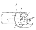
- Fig. 1 illustrates a drip chamber 5 and membrane support 10.
- Membrane support 10 includes a support member 7 preferably constructed of a short, open-ended cylinder with a central, generally circular support surface 12, most preferably integrally formed therewith, such as by injection molding.
- Support member 7 has a longitudinal axis 8 and two ends 9.
- Support surface 12 extends inwards from an inner wall of the support member 7 at a distance from both ends 9.
- Support surface 12 may be slightly conical in shape, although it is appreciated that any arbitrary shape may be used.
- Support surface 12 preferably has a peripheral rim 14 to which a generally circular membrane 16 (shown partially in Fig. 1) can be joined.
- reference to two materials or elements being “joined” refers to the situation wherein the two materials or elements are directly joined to one another or where they are indirectly joined to one another such as where both are joined to an intermediate element.
- methods of joining two materials or elements include forming the elements or materials integrally, or attaching the elements together such as through the use of sonic or thermal bonding, welding, and the like.
- An outlet 11 preferably extends from support surface 12 and is formed with a bore 18. Outlet 11 is connectable to downstream tubing (not shown) of an infusion set (not shown).
- Membrane support 10 is preferably bonded to DC 5 by applying a small amount of adhesive to a bottom surface 19 of DC 5. The adhesive is never in close contact with membrane 16 and possible damage is minimized.
- DC 5 is connected to an infusion bag (not shown) in the usual manner.
- membrane 16 wets within a few seconds. Thereafter air cannot escape DC 5 at pressures below the bubble point of membrane 16.
- This bubble point pressure varies according to membrane pore size and can be chosen over a wide range, for example 0.05-5 atm. For a typical infusion set use, a bubble point pressure of 0.5-1 atm. will be suitable, corresponding to a pore size rating of 1-5 ⁇ m.
- Membrane 16 may be a bacterially retentive membrane. Such membranes have a pore size rating of 0.2 ⁇ m and below and are capable of retaining most known bacteria even at high volume concentration. Such a membrane can be built into DC 5 with its generally circular configuration, as described above. However, this configuration is generally not suitable for bacterially retentive membranes, because such membranes are quite "tight" and therefore provide relatively low liquid throughputs. The surface area provided by the circular configuration (about 1 cm 2 ) is too small for either gravity or pump driven infusion.
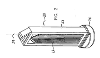
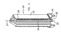
- Figs. 2 and 3 illustrate a membrane support 20 constructed and operative in the present invention.
- the membrane area is substantially increased by arranging the membrane surface generally parallel to the DC longitudinal axis, instead of perpendicular as in the embodiment of Fig. 1, as is now described.
- the increased membrane area is a significant advantage because it enables use of bacterially retentive membranes with good liquid throughputs.
- Membrane support 20 preferably includes an upright, generally rectangular support member 22 with a generally circular base 24.
- a membrane 26 is joined to one or both large support faces of support member 22.
- a membrane surface area of 5-7 cm 2 can easily be achieved in this embodiment.
- the membrane surface is generally parallel to a longitudinal axis 27 of membrane support 20 and a drip chamber (not shown).
- a drain outlet 28 (Fig. 3) is preferably located at an upper portion of support member 22 in order to drain all air from the downstream volume of support member 23. Filtrate can flow from drain outlet 28 via a conduit 30 to an outlet 32.
- Outlet 32 is preferably formed with a bore 33 and is connectable to downstream tubing (not shown) of an infusion set (not shown).
- membrane support 20 is preferably bonded to a DC (not shown) by applying a small amount of adhesive to a bottom surface of the DC. The adhesive is never in close contact with membrane 26 and possible damage is minimized.
- Figs. 2 and 3 has an additional advantage.
- Standard DC's are limited to an upright configuration. Turning the DC upside down will cause the trapped air to dangerously escape into the infusion line, and infusion fluid to fill the DC completely.
- the embodiment of Fig. 1 can prevent air loss. However that embodiment will not function in an upside-down orientation because air will contact the air-impermeable membrane 16.
- Figs. 2 and 3 prevents air escape and functions in all orientations.
- liquid will be in contact with membrane 26 in both the upright and turned-over configurations.
- This DC is therefore suitable also for emergency use, where an upright orientation cannot always be assured.
- a membrane-containing drip chamber was constructed in accordance with the embodiment of Fig. 1. An 8 ⁇ m rated nitrocellulose membrane was welded into the cylindrical insert. The MDC was incorporated in a standard infusion set. The gravitational flow rate was measured by connecting the set to an infusion bag containing saline and setting the outlet 1 m below the bag.
- Flow rate ranged between 125 ml/min and 160 ml/min. The rate remained above 100 ml/min after 5 months of aging at 50°C. This rate conforms to International Standard for Infusion Equipment ISO 8536-4 (1998).
- An MDC was constructed in accordance with the embodiment of Figs. 2 and 3, using a 0.2 ⁇ m rated polysulfone membrane. Minimum bubble point was measured by incorporating the drip chamber in an infusion set, priming it with saline and allowing excess liquid to drain by gravity The MDC with wetted membrane was then pressurized by air to 2 atm. No air was detected at the outlet, indicating a bubble point higher than 2 atm. The MDC was then challenged with a bacteria suspension by aseptically connecting the set to an infusion bag containing sterile saline. An inoculum of pseudomonas diminutal was injected through the injection site so that the final concentration was 10 6 CFU/ml. The whole bag (100 ml) was then drained through the MDC into an empty, sterile bag. The receiving bag was then tested for sterility. No CFU's were detected.
Landscapes
- Health & Medical Sciences (AREA)
- Vascular Medicine (AREA)
- Engineering & Computer Science (AREA)
- Anesthesiology (AREA)
- Biomedical Technology (AREA)
- Heart & Thoracic Surgery (AREA)
- Hematology (AREA)
- Life Sciences & Earth Sciences (AREA)
- Animal Behavior & Ethology (AREA)
- General Health & Medical Sciences (AREA)
- Public Health (AREA)
- Veterinary Medicine (AREA)
- Emergency Medicine (AREA)
- Infusion, Injection, And Reservoir Apparatuses (AREA)
Abstract
Description
- The present invention relates generally to drip chambers used with intravenous infusion sets and particularly to drip chambers with membrane supports.
- Intravenous infusion sets commonly include drip chambers (DCs) to enable the flow rate of an infusion liquid to be visually observed. In a typical installation, an infusion bag is suspended above a patient and a spike at an inlet of the DC pierces the bag, whereby the infusion liquid drips into the DC. The flow rate of the infusion liquid may be observed by the rate of formation of drops of the liquid from the inlet into the DC down through an outlet of the DC which is connected to tubing to the patient. The DC helps prevent air from entering the downstream tubing. This is achieved by a liquid layer acting as an air barrier at the bottom of the chamber. It is formed by manual "priming" (squeezing) of the chamber before the start of infusion.
- Commercial drip chambers are constructed simply of a flexible, transparent cylinder with inlet and outlet. They also often contain a screen at the bottom, acting as a coarse filter preventing particles from entering the vein.
- It is desirable to have a finer filter such as a hydrophilic membrane, ideally a bacteria retentive membrane, incorporated into the DC. This is advantageous in that it obviates the use of an extra filter often connected downstream of the infusion set. More importantly, such a membrane has the advantage of solving the following problem often encountered in infusion. When the infusion bag empties, so does the DC. As the above mentioned liquid layer is now absent, air enters the tubing downstream of the DC. This necessitates opening the system and repriming the set before infusion can be continued. By using a hydrophilic membrane at the DC outlet, liquid flow is not impeded, yet air intrusion is substantially prevented at all pressures below the membrane "bubble point". Thus after the infusion bag empties a new bag can be connected and infusion restarted without need for repriming.
- A few patents (e.g. US 4,013.072, US 4,521,212 and US 5,903,281 assigned to the applicant/assignee, the disclosures of which are incorporated herein by reference) have described infusion devices that include membranes, however no simple, membrane-based infusion set is available commercially. The reasons for this are both technological and commercial. Membranes are sensitive structures and may easily be affected by solvents, glues and other bonding means. Also, infusion sets need to conform to certain flow and accuracy criteria which may be affected by the membrane. Additionally the infusion set must remain inexpensive even with the membrane incorporated.
- Another infusion device with a membrane is described in US Patent 5,779,674 to Ford. In this device, a hydrophilic membrane is attached to a support structure and may be horizontally or vertically oriented. However, this device has a drawback of the membrane being situated close to a base which is bonded with an adhesive to a drip chamber, meaning that the membrane can possible come into contact with the adhesive. In addition, the structure of the membrane support is such that air entrapped downstream of the membrane, between the membrane and drip chamber outlet, can occasionally escape into the infusion line, thus defeating the whole purpose of the membrane drip chamber.
- The need therefore exists for an economical, accurate, high throughput, membrane-containing drip chamber that poses no danger of air escaping into the infusion line.
- EP-A- 0 788 824 discloses a membrane support including a membrane joined to a support face of a support member, wherein the support member is connected (integral) with the drip chamber inlet.
- In US-A-4 013 072 there is described a drip chamber according to the preamble of claim 1. More specifically, US-A-4 013 074 discloses a drip chamber comprising a membrane support featuring a support member having a longitudinal axis and at least one support face, and a membrane joined to said at least one said support face, the support member being connected to an outlet end of the drip chamber, wherein the membrane divides the drip chamber into two volumes such that fluid flowing through the drip chamber has to pass through the membrane. In the above US-A-4 013 072, the membrane support is in the form of a cage with an impermeable bottom and a membrane sealed on the inside. Liquid permeates from inside the cage to the periphery through the membrane trapping air in the downstream volume.
- It is a primary objective of the present invention to provide an improved drip chamber that permits safe mounting of the membrane into the drip chamber and that poses no danger of air escaping into the infusion line.
- To achieve this, the drip chamber of the invention is characterized by the features claimed in the characterizing part of claim 1.
- Basically, according to the invention, a volume downstream of the support face and the membrane comprises a drain outlet at an upper portion of the support member, the drain outlet fluidly communicating with a relatively narrow conduit, and the conduit fluidly communicating with a support member outlet located near ah outlet of the drip chamber, wherein the membrane is positioned with respect to the outlet of the drip chamber such that, when the drip chamber is primed with infusion solution and in a normal upright orientation, the downstream volume is completely filled with infusion solution with no air penetrating below the membrane.
- The present invention seeks to provide an improved drip chamber having a membrane support that permits safe mounting of a membrane, e.g., a hydrophilic or bacterially retentive membrane, into the drip chamber with no danger of contaminating or ruining the membrane with adhesive and the like. The membrane support includes a support member that supports the membrane at a safe distance from ends of the support member which are bonded to the drip chamber with adhesive. The membrane is generally parallel to the longitudinal axis. This permits using a membrane with a significantly larger surface area and is particularly useful for a bacterially retentive membrane.
- There is thus provided a membrane support for assembly into a drip chamber, including a support member having a longitudinal axis, two ends and at least one support face distanced from both ends and generally parallel to the longitudinal axis, a membrane joined to the at least one the support face, and a support member outlet formed in the support member and in fluid communication with the membrane, the support member outlet being fluidly communicable with an outlet of a drip chamber.
- In accordance with the present invention a drain outlet is located at an upper portion of the support member, the support member being formed with a conduit which fluidly connects the drain outlet to the support member outlet.
- Further in accordance with a preferred embodiment of the present invention the membrane support is bonded to a drip chamber with an adhesive, the adhesive not contacting the membrane.
- Still further in accordance with a preferred embodiment of the present invention the membrane has a surface area of at least about 5 cm2. The support member outlet may be connectable to downstream tubing of an infusion set.
- The present invention will be understood and appreciated more fully from the following detailed description, taken in conjunction with the drawings in which:
- Fig. 1 is a simplified pictorial illustration of a membrane support and drip chamber, and
- Figs. 2 and 3 are simplified pictorial and cutaway illustrations, respectively, of a membrane support comprised in the drip chamber according to the present invention.
- Reference is now made to Fig. 1 which illustrates a drip chamber 5 and
membrane support 10. -
Membrane support 10 includes asupport member 7 preferably constructed of a short, open-ended cylinder with a central, generallycircular support surface 12, most preferably integrally formed therewith, such as by injection molding.Support member 7 has a longitudinal axis 8 and twoends 9. -
Support surface 12 extends inwards from an inner wall of thesupport member 7 at a distance from bothends 9.Support surface 12 may be slightly conical in shape, although it is appreciated that any arbitrary shape may be used.Support surface 12 preferably has aperipheral rim 14 to which a generally circular membrane 16 (shown partially in Fig. 1) can be joined. As used herein, reference to two materials or elements being "joined" refers to the situation wherein the two materials or elements are directly joined to one another or where they are indirectly joined to one another such as where both are joined to an intermediate element. Similarly, methods of joining two materials or elements include forming the elements or materials integrally, or attaching the elements together such as through the use of sonic or thermal bonding, welding, and the like. - An
outlet 11 preferably extends fromsupport surface 12 and is formed with abore 18.Outlet 11 is connectable to downstream tubing (not shown) of an infusion set (not shown).Membrane support 10 is preferably bonded to DC 5 by applying a small amount of adhesive to abottom surface 19 of DC 5. The adhesive is never in close contact withmembrane 16 and possible damage is minimized. - DC 5 is connected to an infusion bag (not shown) in the usual manner. When DC 5 is first primed,
membrane 16 wets within a few seconds. Thereafter air cannot escape DC 5 at pressures below the bubble point ofmembrane 16. This bubble point pressure varies according to membrane pore size and can be chosen over a wide range, for example 0.05-5 atm. For a typical infusion set use, a bubble point pressure of 0.5-1 atm. will be suitable, corresponding to a pore size rating of 1-5µm. - Upon emptying of the infusion bag, liquid level in DC 5 will recede and reach exactly the height of
membrane 16. No air will penetrate belowmembrane 16. Thus the downstream infusion line will remain primed. A new bag can, therefore, be connected upstream of DC 5 and infusion continued with no need for repriming. -
Membrane 16 may be a bacterially retentive membrane. Such membranes have a pore size rating of 0.2 µm and below and are capable of retaining most known bacteria even at high volume concentration. Such a membrane can be built into DC 5 with its generally circular configuration, as described above. However, this configuration is generally not suitable for bacterially retentive membranes, because such membranes are quite "tight" and therefore provide relatively low liquid throughputs. The surface area provided by the circular configuration (about 1 cm2) is too small for either gravity or pump driven infusion. - Reference is now made to Figs. 2 and 3 which illustrate a
membrane support 20 constructed and operative in the present invention. Inmembrane support 20, the membrane area is substantially increased by arranging the membrane surface generally parallel to the DC longitudinal axis, instead of perpendicular as in the embodiment of Fig. 1, as is now described. The increased membrane area is a significant advantage because it enables use of bacterially retentive membranes with good liquid throughputs. -
Membrane support 20 preferably includes an upright, generallyrectangular support member 22 with a generallycircular base 24. Amembrane 26 is joined to one or both large support faces ofsupport member 22. A membrane surface area of 5-7 cm2 can easily be achieved in this embodiment. The membrane surface is generally parallel to alongitudinal axis 27 ofmembrane support 20 and a drip chamber (not shown). A drain outlet 28 (Fig. 3) is preferably located at an upper portion ofsupport member 22 in order to drain all air from the downstream volume of support member 23. Filtrate can flow fromdrain outlet 28 via aconduit 30 to anoutlet 32.Outlet 32 is preferably formed with abore 33 and is connectable to downstream tubing (not shown) of an infusion set (not shown). As similarly described above for the embodiment of Fig. 1,membrane support 20 is preferably bonded to a DC (not shown) by applying a small amount of adhesive to a bottom surface of the DC. The adhesive is never in close contact withmembrane 26 and possible damage is minimized. - Using the configuration of Figs. 2 and 3, high gravity infusion flow rates are achievable. In pump driven infusion, little effect on pump accuracy is seen.
- The configuration of Figs. 2 and 3 has an additional advantage. Standard DC's are limited to an upright configuration. Turning the DC upside down will cause the trapped air to dangerously escape into the infusion line, and infusion fluid to fill the DC completely. The embodiment of Fig. 1 can prevent air loss. However that embodiment will not function in an upside-down orientation because air will contact the air-
impermeable membrane 16. - In contrast, the embodiment of Figs. 2 and 3 prevents air escape and functions in all orientations. When properly primed, liquid will be in contact with
membrane 26 in both the upright and turned-over configurations. This DC is therefore suitable also for emergency use, where an upright orientation cannot always be assured. - Two examples of tests performed with the above described embodiments are now described.
- A membrane-containing drip chamber (MDC) was constructed in accordance with the embodiment of Fig. 1. An 8 µm rated nitrocellulose membrane was welded into the cylindrical insert. The MDC was incorporated in a standard infusion set. The gravitational flow rate was measured by connecting the set to an infusion bag containing saline and setting the outlet 1 m below the bag.
- Flow rate ranged between 125 ml/min and 160 ml/min. The rate remained above 100 ml/min after 5 months of aging at 50°C. This rate conforms to International Standard for Infusion Equipment ISO 8536-4 (1998).
- In order to test prevention of air intrusion, the set was opened to the atmosphere. No air leaked into the downstream line for at least 8 hours.
- An MDC was constructed in accordance with the embodiment of Figs. 2 and 3, using a 0.2 µm rated polysulfone membrane. Minimum bubble point was measured by incorporating the drip chamber in an infusion set, priming it with saline and allowing excess liquid to drain by gravity The MDC with wetted membrane was then pressurized by air to 2 atm. No air was detected at the outlet, indicating a bubble point higher than 2 atm. The MDC was then challenged with a bacteria suspension by aseptically connecting the set to an infusion bag containing sterile saline. An inoculum of pseudomonas diminutal was injected through the injection site so that the final concentration was 106 CFU/ml. The whole bag (100 ml) was then drained through the MDC into an empty, sterile bag. The receiving bag was then tested for sterility. No CFU's were detected.
- It will be appreciated by persons skilled in the art that the present invention is not limited by what has been particularly shown and described hereinabove. Rather the scope of the present invention is defined in the appended claims.
Claims (9)
- A drip chamber (5) comprising a membrane support (20), the membrane support (20) featuring a support member (22) having a longitudinal axis (27) and at least one support face, and a membrane (26) joined to said at least one said support face parallel to the longitudinal axis,
said support member (22) being connected to an outlet end of said drip chamber (5),
and having a base (24) and an upper portion,
wherein said membrane (26) divides the drip chamber (5) into two volumes such that fluid flowing through the drip chamber (5) has to pass through the membrane (26),
characterized in that it is the base (24) which is connected to said outlet end of said drip chamber, and a volume downstream of said volume downstream of said support face and said membrane (26) comprises a drain outlet (28) at the upper portion of said support member (22), said drain outlet (28) fluidly communicating with a relatively narrow conduit (30),
said conduit (30) fluidly, communicating with a support member outlet (32) located of the base (24) and near an outlet of said drip chamber (5),
wherein said membrane (26) is positioned with respect to said outlet end of said drip member (5) such that, when said drip chamber (5) is primed with infusion solution and in a normal upright orientation, said downstream volume is completely filled with infusion solution with no air penetrating below said membrane (26). - The drip chamber (5) according to claim 1, characterized in that said membrane support (20) is bonded to said drip chamber (5) with an adhesive, said adhesive not contacting said membrance (26).
- The drip chamber (5) according to claim 1, characterized in that said membrane support (20) is bonded to said drip chamber (5) by sonic or thermal bonding.
- The drip chamber (5) according to claim 1, characterized in that said membrane support (20) is bonded to said drip chamber (5) by welding.
- The drip chamber (5) according to claim 1, characterized in that said membrane (26) is hydrophilic.
- The drip chamber (5) according to claim 1, characterized in that said membrane (26) is microorganism retentive.
- The drip chamber (5) according to claim 1, characterized in that said at least one support face is generally parallel to the longitudinal axis (27) of said drip chamber (5).
- The drip chamber (5) according to claim 1, characterized in that said membrane (26) has a surface area of at least about 5 cm2.
- The drip chamber (5) according to any of the preceding claims, wherein when said drip chamber (5) is primed with the infusion solution, the solution will be in contact with said membrane (26) in both upright and tumed-over configurations.
Applications Claiming Priority (4)
| Application Number | Priority Date | Filing Date | Title |
|---|---|---|---|
| IL133495A IL133495A (en) | 1999-12-13 | 1999-12-13 | Membrane support for drip chamber |
| IL13349599 | 1999-12-13 | ||
| PCT/IL2000/000560 WO2001041844A1 (en) | 1999-12-13 | 2000-09-12 | Membrane support for drip chamber |
| US10/152,004 US20030220616A1 (en) | 1999-12-13 | 2002-05-22 | Membrane support for drip chamber |
Publications (2)
| Publication Number | Publication Date |
|---|---|
| EP1237602A1 EP1237602A1 (en) | 2002-09-11 |
| EP1237602B1 true EP1237602B1 (en) | 2007-03-07 |
Family
ID=38626570
Family Applications (1)
| Application Number | Title | Priority Date | Filing Date |
|---|---|---|---|
| EP00960945A Expired - Lifetime EP1237602B1 (en) | 1999-12-13 | 2000-09-12 | Drip chamber with membrane support |
Country Status (6)
| Country | Link |
|---|---|
| US (2) | US20030220616A1 (en) |
| EP (1) | EP1237602B1 (en) |
| AU (1) | AU7309200A (en) |
| DE (1) | DE60033846T2 (en) |
| IL (1) | IL133495A (en) |
| WO (1) | WO2001041844A1 (en) |
Families Citing this family (44)
| Publication number | Priority date | Publication date | Assignee | Title |
|---|---|---|---|---|
| ITMI20022473A1 (en) * | 2002-11-21 | 2004-05-22 | Gvs Spa | INFUSION FILTER OPERATING EFFECTIVELY IN VARIOUS SPACE POSITIONS. |
| US8864725B2 (en) | 2009-03-17 | 2014-10-21 | Baxter Corporation Englewood | Hazardous drug handling system, apparatus and method |
| US9151646B2 (en) | 2011-12-21 | 2015-10-06 | Deka Products Limited Partnership | System, method, and apparatus for monitoring, regulating, or controlling fluid flow |
| PL2399621T3 (en) * | 2010-06-25 | 2017-01-31 | Codan Holding Gmbh | Drip chamber with ventilation valve |
| US9128051B2 (en) | 2010-10-19 | 2015-09-08 | Baxter International Inc. | Optical imaging system for air bubble and empty bag detection in an infusion tube |
| US9476825B2 (en) | 2010-10-19 | 2016-10-25 | Baxter International Inc. | Optical imaging system with multiple imaging channel optical sensing |
| US8622979B2 (en) | 2010-10-19 | 2014-01-07 | Baxter Healthcare S.A. | Infusion system using optical imager for controlling flow and method thereof |
| US9144644B2 (en) | 2011-08-02 | 2015-09-29 | Baxter International Inc. | Infusion pump with independently controllable valves and low power operation and methods thereof |
| US9435455B2 (en) | 2011-12-21 | 2016-09-06 | Deka Products Limited Partnership | System, method, and apparatus for monitoring, regulating, or controlling fluid flow |
| US9746094B2 (en) | 2011-12-21 | 2017-08-29 | Deka Products Limited Partnership | Flow meter having a background pattern with first and second portions |
| US10488848B2 (en) | 2011-12-21 | 2019-11-26 | Deka Products Limited Partnership | System, method, and apparatus for monitoring, regulating, or controlling fluid flow |
| US10228683B2 (en) | 2011-12-21 | 2019-03-12 | Deka Products Limited Partnership | System, method, and apparatus for monitoring, regulating, or controlling fluid flow |
| US9746093B2 (en) | 2011-12-21 | 2017-08-29 | Deka Products Limited Partnership | Flow meter and related system and apparatus |
| US10563681B2 (en) | 2011-12-21 | 2020-02-18 | Deka Products Limited Partnership | System, method, and apparatus for clamping |
| US9372486B2 (en) | 2011-12-21 | 2016-06-21 | Deka Products Limited Partnership | System, method, and apparatus for monitoring, regulating, or controlling fluid flow |
| US9724466B2 (en) | 2011-12-21 | 2017-08-08 | Deka Products Limited Partnership | Flow meter |
| US9759343B2 (en) | 2012-12-21 | 2017-09-12 | Deka Products Limited Partnership | Flow meter using a dynamic background image |
| US8974414B2 (en) | 2013-02-13 | 2015-03-10 | Becton, Dickinson And Company | IV drip chamber with filter and bottom reservoir |
| US9234850B2 (en) | 2013-03-14 | 2016-01-12 | Baxter International Inc. | Drip chamber with integrated optics |
| US9352081B2 (en) | 2013-03-14 | 2016-05-31 | Baxter International Inc. | Drip chamber with hydrophobic interior surface |
| US20150018765A1 (en) * | 2013-07-09 | 2015-01-15 | Welford Manufacturing (M) SDN BHD | Infusion set that prevents air entry into infusion tubing |
| USD745661S1 (en) | 2013-11-06 | 2015-12-15 | Deka Products Limited Partnership | Apparatus to control fluid flow through a tube |
| USD751689S1 (en) | 2013-11-06 | 2016-03-15 | Deka Products Limited Partnership | Apparatus to control fluid flow through a tube |
| USD752209S1 (en) | 2013-11-06 | 2016-03-22 | Deka Products Limited Partnership | Apparatus to control fluid flow through a tube |
| USD751690S1 (en) | 2013-11-06 | 2016-03-15 | Deka Products Limited Partnership | Apparatus to control fluid flow through a tube |
| USD749206S1 (en) | 2013-11-06 | 2016-02-09 | Deka Products Limited Partnership | Apparatus to control fluid flow through a tube |
| JP2017516570A (en) * | 2014-05-28 | 2017-06-22 | フレゼニウス カービ ドイチュラント ゲーエムベーハー | Drip chamber for administration of medical fluid |
| EP3233153A4 (en) | 2014-12-17 | 2018-07-11 | Mobile I.V. Systems LLC | Drip chamber assembly that functions irrespective of orientation |
| US20160213862A1 (en) * | 2015-01-27 | 2016-07-28 | Becton, Dickinson And Company | Iv set having an air stop membrane |
| US20160213861A1 (en) | 2015-01-27 | 2016-07-28 | Becton, Dickinson And Company | Air stop membrane for maintaining a fluid column in an iv set |
| US10702689B2 (en) | 2015-03-26 | 2020-07-07 | Becton, Dickinson And Company | Auto-stop vent plug |
| US10232130B2 (en) | 2015-03-26 | 2019-03-19 | Becton, Dickinson And Company | Anti-run dry membrane |
| US10201667B2 (en) * | 2015-03-26 | 2019-02-12 | Becton, Dickinson And Company | IV membrane attachment systems and methods |
| US10105899B2 (en) * | 2015-03-26 | 2018-10-23 | Becton, Dickinson And Company | IV membrane attachment systems and methods |
| US10646648B2 (en) | 2015-04-01 | 2020-05-12 | Becton, Dickinson And Company | IV flow management systems and methods |
| WO2016204906A1 (en) * | 2015-06-15 | 2016-12-22 | Enspero Inc. | Multiport delivery device |
| EP4335471A3 (en) | 2016-01-28 | 2024-08-21 | DEKA Products Limited Partnership | Apparatus for monitoring, regulating, or controlling fluid flow |
| USD905848S1 (en) | 2016-01-28 | 2020-12-22 | Deka Products Limited Partnership | Apparatus to control fluid flow through a tube |
| USD854145S1 (en) | 2016-05-25 | 2019-07-16 | Deka Products Limited Partnership | Apparatus to control fluid flow through a tube |
| CN106563185A (en) * | 2016-07-08 | 2017-04-19 | 蔡根顺 | Precision type intelligent dripping bucket with automatic drainage and liquid storage functions, and liquid storage floating body |
| KR102240665B1 (en) * | 2019-05-23 | 2021-04-15 | 위더스 주식회사 | Medical drip chamber |
| USD964563S1 (en) | 2019-07-26 | 2022-09-20 | Deka Products Limited Partnership | Medical flow clamp |
| WO2021021596A1 (en) | 2019-07-26 | 2021-02-04 | Deka Products Limited Partnership | Apparatus for monitoring, regulating, or controlling fluid flow |
| US20220080107A1 (en) * | 2020-09-11 | 2022-03-17 | Carefusion 303. Inc. | Drip chamber assembly |
Family Cites Families (19)
| Publication number | Priority date | Publication date | Assignee | Title |
|---|---|---|---|---|
| US3003500A (en) * | 1955-12-14 | 1961-10-10 | Baxter Laboratories Inc | Intravenous administration equipment |
| US2901112A (en) * | 1957-05-10 | 1959-08-25 | Michael Reese Res Foundation I | Combining tube and filter therefor |
| NO760938L (en) * | 1975-03-22 | 1976-09-23 | Biotest Serum Institut Gmbh | |
| US4009714A (en) * | 1975-07-30 | 1977-03-01 | Johnson & Johnson | Intravenous solution filter unit |
| US4013072A (en) * | 1975-11-03 | 1977-03-22 | Baxter Travenol Laboratories, Inc. | Drip chamber for intravenous administration |
| US4116646A (en) * | 1977-05-20 | 1978-09-26 | Millipore Corporation | Filter unit |
| US4173223A (en) * | 1977-10-17 | 1979-11-06 | National Patent Development Corporation | Chamber assembly for infusion and transfusion apparatus |
| US4276170A (en) * | 1978-08-16 | 1981-06-30 | Critikon, Inc. | Vented flexible filtration device for use in administering parenteral liquids |
| US4395260A (en) * | 1981-06-01 | 1983-07-26 | Sorenson Research Co., Inc. | Drip chamber |
| US4400277A (en) * | 1981-06-25 | 1983-08-23 | Filtertek, Inc. | Low-profile inline filter |
| US4547190A (en) * | 1982-11-26 | 1985-10-15 | Filtertek, Inc. | Inlet blood filter assembly |
| US5439587A (en) * | 1993-07-27 | 1995-08-08 | Millipore Corporation | Self priming filter apparatus |
| CA2196827A1 (en) * | 1996-02-06 | 1997-08-07 | Ricky R. Ruschke | Filter and method of manufacture |
| US5779674A (en) * | 1996-05-06 | 1998-07-14 | Mallinckrodt Medical, Inc. | Fluid gas removal drip chamber |
| IL120693A (en) * | 1997-04-17 | 2001-11-25 | Teva Medical Ltd | Flow indicators for ambulatory infusion |
| US6497685B1 (en) * | 2000-03-24 | 2002-12-24 | Baxter International Inc. | Integral intravenous chamber and filter |
| US6913590B2 (en) * | 2000-09-22 | 2005-07-05 | Sorenson Development, Inc. | Apparatus and method for peritoneal dialysis |
| ITBO20000662A1 (en) * | 2000-11-15 | 2002-05-15 | Gvs S R L | INFUSION FILTER |
| US6575943B1 (en) * | 2002-01-16 | 2003-06-10 | Chang Hsiao-Yun Emma | Prewarning device for instillation of medical liquid |
-
1999
- 1999-12-13 IL IL133495A patent/IL133495A/en not_active IP Right Cessation
-
2000
- 2000-09-12 WO PCT/IL2000/000560 patent/WO2001041844A1/en not_active Ceased
- 2000-09-12 DE DE60033846T patent/DE60033846T2/en not_active Expired - Lifetime
- 2000-09-12 AU AU73092/00A patent/AU7309200A/en not_active Abandoned
- 2000-09-12 EP EP00960945A patent/EP1237602B1/en not_active Expired - Lifetime
-
2002
- 2002-05-22 US US10/152,004 patent/US20030220616A1/en not_active Abandoned
-
2007
- 2007-02-21 US US11/677,054 patent/US7892204B2/en not_active Expired - Fee Related
Also Published As
| Publication number | Publication date |
|---|---|
| IL133495A0 (en) | 2001-04-30 |
| IL133495A (en) | 2006-12-31 |
| DE60033846T2 (en) | 2007-11-29 |
| US7892204B2 (en) | 2011-02-22 |
| EP1237602A1 (en) | 2002-09-11 |
| WO2001041844A1 (en) | 2001-06-14 |
| DE60033846D1 (en) | 2007-04-19 |
| AU7309200A (en) | 2001-06-18 |
| US20030220616A1 (en) | 2003-11-27 |
| US20070142790A1 (en) | 2007-06-21 |
Similar Documents
| Publication | Publication Date | Title |
|---|---|---|
| EP1237602B1 (en) | Drip chamber with membrane support | |
| US4568366A (en) | In-line filter | |
| US5126054A (en) | Venting means | |
| EP0957951B1 (en) | Fluid gas removal drip chamber | |
| EP0102748B1 (en) | Parenteral solution administration set | |
| US4173222A (en) | Apparatus for controllably administering a parenteral fluid | |
| CA1123698A (en) | Arrangement for intravenous administration or the like | |
| EP2214753B1 (en) | Safety vent structure for extracorporeal circuit | |
| CA1098049A (en) | Filter unit | |
| EP0381757B1 (en) | Medical instrument and production thereof | |
| EP1559442B1 (en) | Intravenous delivery system | |
| JP3681392B2 (en) | Dripping chamber head | |
| US4615694A (en) | Vented cone filter | |
| EP0161803B1 (en) | Blood filter | |
| US4941875A (en) | I.V. system for successive administration of two or more solutions at different rates | |
| US4412916A (en) | Airless artificial kidney assembly | |
| EP0711183A1 (en) | Self priming filter apparatus | |
| WO1997009106A1 (en) | An in-line blood filtration device | |
| US4056100A (en) | Volume limiting chamber | |
| US6193689B1 (en) | Intravenous liquid flow regulator | |
| US4287065A (en) | Filter hub assembly | |
| US6013060A (en) | Intravenous liquid flow regulator | |
| EP0247213A1 (en) | Filter for eliminating air | |
| JPS6316146B2 (en) | ||
| JPS6040299B2 (en) | Blood defoaming purification reservoir |
Legal Events
| Date | Code | Title | Description |
|---|---|---|---|
| PUAI | Public reference made under article 153(3) epc to a published international application that has entered the european phase |
Free format text: ORIGINAL CODE: 0009012 |
|
| 17P | Request for examination filed |
Effective date: 20020709 |
|
| AK | Designated contracting states |
Kind code of ref document: A1 Designated state(s): AT BE CH CY DE DK ES FI FR GB GR IE IT LI LU MC NL PT SE |
|
| AX | Request for extension of the european patent |
Free format text: AL;LT;LV;MK;RO;SI |
|
| 17Q | First examination report despatched |
Effective date: 20031211 |
|
| RBV | Designated contracting states (corrected) |
Designated state(s): AT BE CH CY DE FR GB IT LI |
|
| RTI1 | Title (correction) |
Free format text: DRIP CHAMBER WITH MEMBRANE SUPPORT |
|
| GRAP | Despatch of communication of intention to grant a patent |
Free format text: ORIGINAL CODE: EPIDOSNIGR1 |
|
| RBV | Designated contracting states (corrected) |
Designated state(s): DE FR GB IT |
|
| GRAS | Grant fee paid |
Free format text: ORIGINAL CODE: EPIDOSNIGR3 |
|
| GRAA | (expected) grant |
Free format text: ORIGINAL CODE: 0009210 |
|
| AK | Designated contracting states |
Kind code of ref document: B1 Designated state(s): DE FR GB IT |
|
| REG | Reference to a national code |
Ref country code: GB Ref legal event code: FG4D |
|
| REF | Corresponds to: |
Ref document number: 60033846 Country of ref document: DE Date of ref document: 20070419 Kind code of ref document: P |
|
| ET | Fr: translation filed | ||
| PLBE | No opposition filed within time limit |
Free format text: ORIGINAL CODE: 0009261 |
|
| STAA | Information on the status of an ep patent application or granted ep patent |
Free format text: STATUS: NO OPPOSITION FILED WITHIN TIME LIMIT |
|
| 26N | No opposition filed |
Effective date: 20071210 |
|
| PGFP | Annual fee paid to national office [announced via postgrant information from national office to epo] |
Ref country code: DE Payment date: 20130919 Year of fee payment: 14 |
|
| PGFP | Annual fee paid to national office [announced via postgrant information from national office to epo] |
Ref country code: GB Payment date: 20130919 Year of fee payment: 14 Ref country code: FR Payment date: 20130919 Year of fee payment: 14 |
|
| PGFP | Annual fee paid to national office [announced via postgrant information from national office to epo] |
Ref country code: IT Payment date: 20130930 Year of fee payment: 14 |
|
| REG | Reference to a national code |
Ref country code: DE Ref legal event code: R119 Ref document number: 60033846 Country of ref document: DE |
|
| GBPC | Gb: european patent ceased through non-payment of renewal fee |
Effective date: 20140912 |
|
| REG | Reference to a national code |
Ref country code: DE Ref legal event code: R119 Ref document number: 60033846 Country of ref document: DE Effective date: 20150401 |
|
| REG | Reference to a national code |
Ref country code: FR Ref legal event code: ST Effective date: 20150529 |
|
| PG25 | Lapsed in a contracting state [announced via postgrant information from national office to epo] |
Ref country code: DE Free format text: LAPSE BECAUSE OF NON-PAYMENT OF DUE FEES Effective date: 20150401 Ref country code: GB Free format text: LAPSE BECAUSE OF NON-PAYMENT OF DUE FEES Effective date: 20140912 |
|
| PG25 | Lapsed in a contracting state [announced via postgrant information from national office to epo] |
Ref country code: FR Free format text: LAPSE BECAUSE OF NON-PAYMENT OF DUE FEES Effective date: 20140930 Ref country code: IT Free format text: LAPSE BECAUSE OF NON-PAYMENT OF DUE FEES Effective date: 20140912 |