EP1237489B1 - Instrument chirurgical pour l'endarteriectomie - Google Patents
Instrument chirurgical pour l'endarteriectomie Download PDFInfo
- Publication number
- EP1237489B1 EP1237489B1 EP00990474A EP00990474A EP1237489B1 EP 1237489 B1 EP1237489 B1 EP 1237489B1 EP 00990474 A EP00990474 A EP 00990474A EP 00990474 A EP00990474 A EP 00990474A EP 1237489 B1 EP1237489 B1 EP 1237489B1
- Authority
- EP
- European Patent Office
- Prior art keywords
- head
- endoscope
- shaft
- surgical instrument
- gas
- Prior art date
- Legal status (The legal status is an assumption and is not a legal conclusion. Google has not performed a legal analysis and makes no representation as to the accuracy of the status listed.)
- Expired - Lifetime
Links
- 238000013171 endarterectomy Methods 0.000 title claims abstract description 23
- 239000012530 fluid Substances 0.000 claims abstract description 19
- FAPWRFPIFSIZLT-UHFFFAOYSA-M Sodium chloride Chemical compound [Na+].[Cl-] FAPWRFPIFSIZLT-UHFFFAOYSA-M 0.000 claims description 16
- 230000007246 mechanism Effects 0.000 claims description 10
- 238000004891 communication Methods 0.000 claims description 8
- 230000008878 coupling Effects 0.000 claims description 5
- 238000010168 coupling process Methods 0.000 claims description 5
- 238000005859 coupling reaction Methods 0.000 claims description 5
- 230000003287 optical effect Effects 0.000 claims description 5
- 238000000034 method Methods 0.000 abstract description 17
- 210000001367 artery Anatomy 0.000 description 43
- 210000002808 connective tissue Anatomy 0.000 description 15
- 238000007789 sealing Methods 0.000 description 14
- 230000017531 blood circulation Effects 0.000 description 5
- CURLTUGMZLYLDI-UHFFFAOYSA-N Carbon dioxide Chemical compound O=C=O CURLTUGMZLYLDI-UHFFFAOYSA-N 0.000 description 4
- PPNXXZIBFHTHDM-UHFFFAOYSA-N aluminium phosphide Chemical compound P#[Al] PPNXXZIBFHTHDM-UHFFFAOYSA-N 0.000 description 4
- 230000007704 transition Effects 0.000 description 4
- 210000004204 blood vessel Anatomy 0.000 description 3
- 229910002092 carbon dioxide Inorganic materials 0.000 description 3
- 238000003825 pressing Methods 0.000 description 3
- 230000000694 effects Effects 0.000 description 2
- 238000002955 isolation Methods 0.000 description 2
- 230000009467 reduction Effects 0.000 description 2
- 238000000926 separation method Methods 0.000 description 2
- 230000015572 biosynthetic process Effects 0.000 description 1
- 239000001569 carbon dioxide Substances 0.000 description 1
- 230000007423 decrease Effects 0.000 description 1
- 210000004013 groin Anatomy 0.000 description 1
- 238000005286 illumination Methods 0.000 description 1
- 210000003127 knee Anatomy 0.000 description 1
- 239000007788 liquid Substances 0.000 description 1
- 239000007769 metal material Substances 0.000 description 1
- 238000012986 modification Methods 0.000 description 1
- 230000004048 modification Effects 0.000 description 1
- 230000001105 regulatory effect Effects 0.000 description 1
- 238000004513 sizing Methods 0.000 description 1
- 210000001519 tissue Anatomy 0.000 description 1
- 238000011144 upstream manufacturing Methods 0.000 description 1
- 210000000626 ureter Anatomy 0.000 description 1
Images


Classifications
-
- A—HUMAN NECESSITIES
- A61—MEDICAL OR VETERINARY SCIENCE; HYGIENE
- A61B—DIAGNOSIS; SURGERY; IDENTIFICATION
- A61B17/00—Surgical instruments, devices or methods
- A61B17/32—Surgical cutting instruments
- A61B17/3205—Excision instruments
- A61B17/3207—Atherectomy devices working by cutting or abrading; Similar devices specially adapted for non-vascular obstructions
-
- A—HUMAN NECESSITIES
- A61—MEDICAL OR VETERINARY SCIENCE; HYGIENE
- A61B—DIAGNOSIS; SURGERY; IDENTIFICATION
- A61B1/00—Instruments for performing medical examinations of the interior of cavities or tubes of the body by visual or photographical inspection, e.g. endoscopes; Illuminating arrangements therefor
- A61B1/012—Instruments for performing medical examinations of the interior of cavities or tubes of the body by visual or photographical inspection, e.g. endoscopes; Illuminating arrangements therefor characterised by internal passages or accessories therefor
- A61B1/015—Control of fluid supply or evacuation
-
- A—HUMAN NECESSITIES
- A61—MEDICAL OR VETERINARY SCIENCE; HYGIENE
- A61B—DIAGNOSIS; SURGERY; IDENTIFICATION
- A61B1/00—Instruments for performing medical examinations of the interior of cavities or tubes of the body by visual or photographical inspection, e.g. endoscopes; Illuminating arrangements therefor
- A61B1/12—Instruments for performing medical examinations of the interior of cavities or tubes of the body by visual or photographical inspection, e.g. endoscopes; Illuminating arrangements therefor with cooling or rinsing arrangements
-
- A—HUMAN NECESSITIES
- A61—MEDICAL OR VETERINARY SCIENCE; HYGIENE
- A61B—DIAGNOSIS; SURGERY; IDENTIFICATION
- A61B1/00—Instruments for performing medical examinations of the interior of cavities or tubes of the body by visual or photographical inspection, e.g. endoscopes; Illuminating arrangements therefor
- A61B1/313—Instruments for performing medical examinations of the interior of cavities or tubes of the body by visual or photographical inspection, e.g. endoscopes; Illuminating arrangements therefor for introducing through surgical openings, e.g. laparoscopes
- A61B1/3132—Instruments for performing medical examinations of the interior of cavities or tubes of the body by visual or photographical inspection, e.g. endoscopes; Illuminating arrangements therefor for introducing through surgical openings, e.g. laparoscopes for laparoscopy
-
- A—HUMAN NECESSITIES
- A61—MEDICAL OR VETERINARY SCIENCE; HYGIENE
- A61B—DIAGNOSIS; SURGERY; IDENTIFICATION
- A61B17/00—Surgical instruments, devices or methods
- A61B17/22—Implements for squeezing-off ulcers or the like on inner organs of the body; Implements for scraping-out cavities of body organs, e.g. bones; for invasive removal or destruction of calculus using mechanical vibrations; for removing obstructions in blood vessels, not otherwise provided for
-
- A—HUMAN NECESSITIES
- A61—MEDICAL OR VETERINARY SCIENCE; HYGIENE
- A61B—DIAGNOSIS; SURGERY; IDENTIFICATION
- A61B17/00—Surgical instruments, devices or methods
- A61B17/00234—Surgical instruments, devices or methods for minimally invasive surgery
- A61B2017/00353—Surgical instruments, devices or methods for minimally invasive surgery one mechanical instrument performing multiple functions, e.g. cutting and grasping
-
- A—HUMAN NECESSITIES
- A61—MEDICAL OR VETERINARY SCIENCE; HYGIENE
- A61B—DIAGNOSIS; SURGERY; IDENTIFICATION
- A61B17/00—Surgical instruments, devices or methods
- A61B17/32—Surgical cutting instruments
- A61B17/3205—Excision instruments
- A61B17/3207—Atherectomy devices working by cutting or abrading; Similar devices specially adapted for non-vascular obstructions
- A61B2017/320741—Atherectomy devices working by cutting or abrading; Similar devices specially adapted for non-vascular obstructions for stripping the intima or the internal plaque from a blood vessel, e.g. for endarterectomy
-
- A—HUMAN NECESSITIES
- A61—MEDICAL OR VETERINARY SCIENCE; HYGIENE
- A61B—DIAGNOSIS; SURGERY; IDENTIFICATION
- A61B90/00—Instruments, implements or accessories specially adapted for surgery or diagnosis and not covered by any of the groups A61B1/00 - A61B50/00, e.g. for luxation treatment or for protecting wound edges
- A61B90/36—Image-producing devices or illumination devices not otherwise provided for
- A61B90/361—Image-producing devices, e.g. surgical cameras
-
- A—HUMAN NECESSITIES
- A61—MEDICAL OR VETERINARY SCIENCE; HYGIENE
- A61B—DIAGNOSIS; SURGERY; IDENTIFICATION
- A61B90/00—Instruments, implements or accessories specially adapted for surgery or diagnosis and not covered by any of the groups A61B1/00 - A61B50/00, e.g. for luxation treatment or for protecting wound edges
- A61B90/36—Image-producing devices or illumination devices not otherwise provided for
- A61B90/37—Surgical systems with images on a monitor during operation
Definitions
- the present invention pertains to surgical instruments and procedures, and more particularly to the removal of plaque build-ups within blood vessels.
- Excessive plaque build-up within arteries decreases the blood flow capacity of the arteries and of the living tissue supplied by the arteries. Normal blood flow may be restored by either removing the plaque build-up or by bypassing the blocked section of the artery.
- a bypass procedure a second blood vessel is attached to, and parallel to, the vessel to be bypassed and provides a flow path around the blocked section of the artery.
- the second blood vessel has one end attached upstream of the blocked section and the second end attached downstream of the blocked section.
- the blockage may be removed from the artery by opening the artery along the blockage and removing the blockage. Both procedures require incisions along the blockage and become extremely invasive for extensive blockages that may run the length from the groin to the knee, for example.
- a less invasive procedure for removing plaque build-ups requires only two incision points; one above the blockage and one below the blockage.
- a catheter is inserted into the artery at the up-stream incision point and is pushed toward the second incision point that is downstream from the blockage.
- the catheter head is configured to either grab or loosen the plaque build-up along the blockage.
- the build-up is pushed ahead of the catheter and is removed at the second incision point. Although the catheter will remove sufficient blockage to restore normal flow, the procedure may not remove all the build-up.
- the catheter head may penetrate through the plaque build-up layer, the intima and media layers of the artery and damage the adventitia layer of the artery.
- the procedure does not remove the blockage from the side branches of the artery and may worsen the blockage of the side branches by a "snowplow" effect.
- gas endarterectomy uses a gas to separate the media layer surrounding the blockage from the adventitia layer of the artery. Once separated from the adventitia layer of the artery, the blockage may be easily removed from the downstream incision point or from the initial incision point if the blockage is less than about an inch. The downstream incision point is still required because the intima and media layers of the artery attached to the blockage site must be separated from the intima and media layers of the non-blocked artery section.
- the gas endarterectomy procedure also requires two incisions, the procedure does not suffer from the "snowplow" effect of the catheter procedure and may also remove the side branch plugs along with the main blockage.
- all plaque is removed in a gas endarterectomy procedure because the underlying intima and media layers containing the plaque are removed.
- the spatula head is removed from the artery and a surgical cutting instrument is inserted into the artery and moved to the end of the blockage whereupon the surgical cutting instrument cuts the intima and media layers of the artery.
- the blockage is then removed from the artery by pulling the blockage through the incision using forceps or the surgical cutting instrument.
- the procedure described in the'713 patent requires two instruments: the spatula instrument and the cutting instrument. Furthermore, both instruments must be worked through the blockage. This increases the duration of the requisite operation and the risk of damage to the adventitia layer of the artery. It is thus preferable to have a single instrument that both separates the media layer from the adventitia layer and then removes the blockage.
- the media and intima layers are preferably cut at the point where the gas endarterectomy has separated the layers from the adventitia layer.
- damage to the adventitia may occur if the cut is made beyond the separation point. If the cut is made behind the separation point, the separated media and intima layers will form a flap within the artery.
- a stent is usually inserted to prevent formation of the flap. The stent covers the transition region between the section of the artery where the media and intima layers have been removed with the blockage and the section of the artery where the media and intima layers are intact.
- US 4,557,255 describes a urteroscope with a telescope assembly and remotely operable jaws for retrieving stones and the like from the ureter.
- US 5,364,365 describes a thin bodied surgical instrument with an obturator spring loaded within a cannula, together with a handle at the opposite end of the cannula.
- the invention relates to an endarterectomy surgical instrument as set out in claim 1.
- the media and intima layer is fairly weak at the transition between the plaque build-up and no-plaque build-up regions. Therefore, by grabbing the blockage and pulling, the blockage will tend to separate from the healthy media and intima layers at the transition without the use of a cutting tool. By eliminating the cutting tool, risk to the patient may be advantageously reduced, additionally, only the diseased portion of the media and intima layers need be removed. Furthermore, in accordance with embodiments of the invention, the break occurs at the point where the healthy media and intima layers are separated, thereby producing a smoother transition region.
- a separate surgical cutting instrument may be eliminated by adding a grabbing or grasping function to the spatula head of the endarterectomy surgical instrument provided in accordance with the present invention.
- the spatula head contains either hooks, barbs, or prongs that can be deployed by the operator.
- the hooks or barbs may be retracted after deployment.
- a gas channel is preferably incorporated into the shaft of the instrument, either as a separate channel or with an endoscope in an optical channel.
- the endarterectomy surgical instrument has a shaft with proximal and distal ends.
- a head coupled to the distal end of the shaft, has an endoscope port and at least one fluid port, while a handle, coupled to the proximal end of the shaft, has a gas supply port in fluid communication with the at least one gas port on the head, a flow valve for metering flow of gas between the gas supply port and the at least one fluid port on the head, and a locking mechanism for retaining an endoscope.
- the endarterectomy surgical instrument may also have saline solution inlet coupled to the handle for coupling a flow of saline solution to the at least one fluid port on the head.
- Fluid connection of the handle to the head of the shaft may be provided through a first lumen, while an endoscope may provide optical coupling through a second lumen between the distal and proximal ends of the shaft.
- the first and second lumens may be separate or identical.
- the instrument also has a grasping device with both a retracted configuration and a deployed configuration, the grasping device extending away from the head in the deployed configuration.
- the grasping device may be a barb or a hook, and it may be controlled by a deployment control disposed on the handle of the instrument.
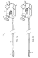
- FIG. 1a shows a perspective view of an embodiment of the present invention in the retracted configuration.
- the gas endarterectomy surgical instrument generally designated by numeral 10 comprises a head 11, connected to a shaft 12, which in turn is connected to a handle 13.
- the handle 13 houses a gas port 14 that connects to a gas supply, not shown.
- the gas flow delivered to the head 11 is controlled by a variable flow valve 15.
- An endoscope latch 16 is provided on the handle 13 to secure an endoscope to the surgical instrument 10.
- the handle also houses a deployment control that controls the deployment or retraction of a grasping device located in the head 11. In the embodiment shown in FIG. 1a, the deployment control is a slide 17.
- the handle 13 is connected to shaft 12 which is a flexible tube providing multiple lumens as now described.
- shaft 12 is sized to provide flow paths both for the gas from the gas supply and for saline solution to the head 11 while also accommodating the endoscope and a control wire, not shown.
- the control wire is attached to the slide 17 on the handle at one end and is attached to the grasping device located in the head 11 at the other end.
- the head 11 is attached to the end of the shaft 12 opposite the end attached to the handle 13.
- the head 11 is provided with an opening that holds the end of the endoscope and also provides exit orifices for the gas and saline solution.
- the head 11 also contains a grasping device that may be deployed by the operation of the deployment control.
- FIG. 1b shows the surgical instrument of FIG. 1a in the deployed configuration. In FIG. 1b, the slide 17 has been moved to the rear position, thereby deploying the grasping mechanism, which, in this embodiment of the invention, is a pair of barbs 18.
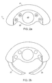
- FIG. 2a shows a front view of head 11 in the retracted configuration of one embodiment of the invention.
- FIG. 2b shows a front view of head 11 in the deployed configuration of the embodiment shown in FIG. 2a.
- Head 11 has an outer side 21 that is shaped to approximate the inner wall of an artery.
- the inner side 22 of head 11 is generally flattened.
- the tip of head 11 contains an endoscope port 23 and a plurality of ports 24 for the delivery of gas and/or saline solution.
- the gas ports are in fluid communication with the gas flow path of the shaft 12 through internal channels within the head 11.
- the end of the endoscope is held by the head by sizing the diameter of the endoscope port 23 to the size of the endoscope.
- FIG. 2b shows the front view of the head 11 in the deployed configuration.
- a plurality of barbs or prongs 25 are deployed from the inner surface 22 and extend away and towards the rear of head 11.
- FIG. 3a shows a front view of head 11 of one embodiment of the invention placed in the artery of a patient.
- the head 11 of the surgical instrument is pushed between the adventitia layer 31 of the artery and the media layer 32 of the artery with the outer side 21 of the head 11 against the adventitia layer 31 of the artery and the inner side 22 of the head 11 facing the media layer 32 of the artery.
- the media layer 32 encircles the intima layer, not shown, on which the plaque forms a build-up layer 33 that obstructs the blood flow channel 34.
- Gas jets from the gas ports 24 separates the adventitia layer 31 from the media layer 32, creating an interstitial chamber 35 through which the head 11 can travel along the blockage caused by the plaque build-up layer 33.
- FIG. 3b shows the front view of the head 11 shown in FIG. 3a with the barbs 25 deployed.
- the barbs 25 are deployed away from the inner surface 22 of the head 11 and extend into the media layer 32 and the build-up layer 33 of the obstruction.
- the rear facing barbs 25 securely grab the obstruction, thereby removing the obstruction as the head 11 is removed from the artery.
- the barbs 25 may also be retracted after deployment by operating the deployment control to retract the barbs 25 while slightly urging the head 11 forward.
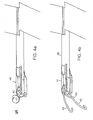
- FIG. 4a shows a perspective view of the head of another embodiment of the present invention.
- FIG. 4b shows a perspective view of the head of the embodiment of the invention shown in FIG. 4a with the grasping mechanism deployed.
- the grasping mechanism comprise a plurality of hooks 43. Hooks 43 are positioned at the front of the head 41 next to the endoscope port 44 . Hooks 43 are housed in channels 45 that terminate at the front of the head. The hooks 43 are attached to a control wire, not shown, that is passed through the shaft 42 and connected at the other end to the deployment control, not shown, on the handle.
- FIG. 5a shows a front view of the embodiment shown in FIG. 4a in the artery.
- FIG. 5b shows a front view of the embodiment shown in FIG. 4a in the artery of a patient in the deployed configuration.
- the head 51 is positioned between the adventitia layer 52 and the media layer 53 of the artery.
- Gas from gas ports 58 is used to open an interstitial space 56 between the adventitia layer 52 and the media layer 53 to allow the head 51 to travel parallel to the build-up layer 54 and the obstructed blood flow channel 55.
- Each hook 43 is housed in a gas flow channel 58. Additional gas flow channels may be provided by side channels 57 on the endoscope port 59.
- the each hook 43 extends forward of the head 51. As the head 51 is removed from the artery, each hook 43 grabs onto the media layer 53 and build-up layer 54 thereby removing the obstruction as the head 51 is removed from the artery.
- FIG. 6 is a side cut view showing the internal channels of the handle in one embodiment of the present invention.
- An external gas source is connected to the surgical instrument by a gas port 14 and supplies gas to the head of the surgical instrument.
- the gas is CO 2 .
- the gas flows through the inlet passageway 610 to a variable flow valve 15, exiting through an outlet passageway 615.
- Outlet passageway 615 is connected to an endoscope passageway 616 which, in turn, is connected to the shaft 12 at the shaft end 617.
- Variable flow valve 15 comprises a knob 620 attached to a control piston 621, the end of which may be displaced into or out of the outlet passageway 615.
- the inlet passageway 610 is isolated from the outlet passageway 615 by a first sealing ring 618.
- the inlet passageway 610 is maintained in fluid isolation with the environment by a second sealing ring 619.
- the first sealing ring 618 is held against the handle body 605 by the control piston 621.
- Control piston 621 has a notch 622 along the side of the piston 621. As control piston 621 is displaced into the outlet passageway 615 by pressing on the knob 620, the notch 622 is moved under the first sealing ring 618.
- Notch 622 relives the pressure placed on the first sealing ring 618 by piston 621.
- the reduction of pressure placed on the first sealing ring 618 allows gas from the inlet passageway 610 to flow around the first sealing ring 618 to the outlet passageway 615.
- the profile of the notch 622 is shaped such that as the piston 621 is displaced further into the outlet passageway 615, more gas is allowed to flow into the outlet passageway 615 from the inlet passageway 610.
- Outlet passageway 615 is in fluid communication with the endoscope passageway 616 thereby allowing gas from the gas supply to flow through shaft 12.
- An endoscope may be placed in endoscope passageway 616 and through shaft 12.
- the endoscope is sized to provide sufficient gas flow between the endoscope and the inner surface of shaft 12 to separate the adventitia layer from the media layer of the artery.
- the endoscope is held in place by an endoscope locking mechanism 16.
- Endoscope locking mechanism 16 may be a latch having a latch pad 630 that holds the endoscope in place when endoscope latch 16 is in a closed position, or, alternatively, the lcoking mechanism may be a quarter turn lock.
- the endoscope is sealed by pressing the endoscope against a wiper seal 633 before locking the endoscope in place.
- the endoscope latch 16 may be released from the closed position to an open position by a latch handle 632.
- the design of the latch handle 632 is well known to one of ordinary skill in the mechanical arts.
- the endoscope latch 16 is moved from a closed position to an open position by rotating the endoscope latch 16 about a pivot 631.
- the surgical instrument 10 may use either a disposable or reusable endoscope from a variety of manufacturers.
- the INTRAMED® angioscope models 700070 (a 1.9 mm disposable), 702016 (1.9 mm diameter; reusable), or 702023 (2.4 mm diameter; reuseable), all from Baxter International, Inc. may be used in the present invention.
- Model A5000 (1.7 mm diameter; disposable angioscope) or Model A5102 (1.7 mm diameter; reusable angioscope), both from Applied Medical Resources of Website of Website, or instruments employing similar principles, may also be used in the present invention.
- surgical instrument 10 may be configured without an endoscope, allowing the physician to decide if an endoscope is necessary for the particular procedure.
- a plug may be used instead of an endoscope to reduce the cost of the procedure.
- the plug is configured to form a seal with the wiper seal 633 and to be held in place by the latch pad 630.
- the plug may also comprise of a length of plastic or metallic material having substantiality the same diameter and length of an endoscope in order to provide additional stiffness to the shaft 12.
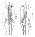
- FIG. 7a shows a cut bottom view of the head of the embodiment shown in FIG. 1a showing the internal passageways within the head.
- Head 11 is attached to shaft 12.
- a control wire 70 is disposed inside shaft 12 and terminates in the head 11 at the wire end 71.
- Wire end 71 connects the end of the control wire 70 to the end of at least one barb wire 72.
- the opposite end of the barb wire 72 is attached to the barb 25.
- Control wire 70, wire end 71, barb wire 72, and barb 25 are positioned in a channel 73 to allow for free movement of the wires 70, 72, wire end 71 and barb 25 within the head 11.
- the channel 73 is in fluid communication with the gas port 24 and endoscope port 23.
- FIG. 7b shows a cut bottom view of the head of the embodiment shown in FIG 1a in the deployed configuration.
- Deployment of the barb 25 is accomplished by withdrawing control wire 70 from head 11.
- the withdrawal of control wire 70 cause wire end 71 and the barb wire 72 to move in a rearward direction away from the endoscope port 23 and toward the handle 13 (not shown).
- the rearward movement of the barb wire 72 pushes barb 25 along channel 73 such that barb tip 75 and barb 25 extend substantially beyond the barb channel opening 74 in the head 11.
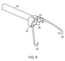
- FIG. 8 shows a perspective view of head 80 of shaft 82, in accordance with other embodiments of the invention.
- Shaft 82 contains at least one lumen for the delivery of gas (typically carbon dioxide) and/or saline solution via one or more ports 84.
- Another lumen through shaft 82 allows an endoscope to emerge at endoscope port 86.
- Endoscope port 86 may be shaped, like the lumen through which the endoscope is threaded, with a notch (or 'sidechannel') 87 to provide for delivery of gas and/or saline solution through the endoscope lumen.
- Two retractable hooks 88 are shown, whereas a third retractable hook is preferably deployed through port 90 but has been omitted to allow clearer depiction of the central region of the head.
- Saline solution is delivered for purposes of keeping the endoscope clear, and thus also the image as viewed by the surgeon.
- Saline solution is preferably delivered through a separate lumen rather than through an endoscope with its own working channel.
- a separate lumen is preferred because the working channel of an endoscope is difficult to sterilize, in that it is an internal space, and thus may require the additional expense of a disposable endoscope.
- An endoscope having a diameter of approximately 0.9 mm and lacking a working channel is preferably employed in this embodiment of the invention.
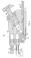
- FIG. 9 is a side cut view showing the internal channels of handle 900 in the embodiment of the present invention depicted in FIG. 8.
- An external gas source is connected to the surgical instrument by a gas port 914 and supplies gas to the head of the surgical instrument.
- the gas is CO 2 .
- the gas flows through the inlet passageway 910 to a variable flow valve 906, exiting through an outlet passageway 915.
- Outlet passageway 915 is connected to channel 908 which carries the gas, saline solution, and control wires through shaft 82. Control wires are brought out of the proximal end of shaft 82 at control wire port 932.
- Endoscope passageway 916 similarly carries the endoscope through shaft 82 to which it is coupled at shaft end 917.
- Variable flow valve 906 comprises a knob 920 attached to a control piston 921, the end of which may be displaced into or out of the outlet passageway 915.
- the inlet passageway 910 is isolated from the outlet passageway 915 by a first sealing ring 918.
- the inlet passageway 910 is maintained in fluid isolation from the environment by a second sealing ring 919.
- the first sealing ring 918 is held against the handle body 905 by the control piston 921.
- Control piston 921 has a notch 922 along the side of piston 921. As control piston 921 is displaced into the outlet passageway 915 by pressing on the knob 920, the notch 922 is moved under the first sealing ring 918.
- Notch 922 relives the pressure placed on the first sealing ring 918 by piston 921.
- the reduction of pressure placed on the first sealing ring 918 allows gas from the inlet passageway 910 to flow around the first sealing ring 918 to the outlet passageway 915.
- the profile of notch 922 is shaped such that as the piston 921 is displaced further into outlet passageway 915, more gas is allowed to flow into the outlet passageway 915 from the inlet passageway 910.
- a second line 936 couples a flow of saline solution for clearing the distal end of the endoscope, as regulated, typically, by a foot pedal 938 operated by the surgeon. Saline solution is coupled, via passageway 915, into the same channel 916 which conveys gas to the distal end of shaft 82.
- Outlet passageway 915 is in fluid communication with channel 908 through which gas, saline solution, and control wires are guided to the distal end of shaft 82.
- An endoscope (not shown, but represented by passageway 916) may be placed in endoscope passageway 916 and through shaft 82.
- the endoscope is sized to provide sufficient gas flow between the endoscope and the inner surface of shaft 82 to separate the adventitia layer from the media layer of the artery.
- the endoscope is held in place by an endoscope locking mechanism 940 having a latch pad 930 that holds the endoscope in place when endoscope locking mechanism 940 is in a closed position.
- gas and saline solution may be conveyed through the same passageway 916 as contains the endoscope.
- a gas-tight seal 933 is preferably used.
- a control wire is used to deploy or retract the grasping device
- a collar may be attached to the endoscope end that engages the grasping device.
- the grasping device may be deployed or retracted by unlocking the endoscope latch on the handle and moving the endoscope forward or backward in the shaft.
- head 11 may be employed in the manner of a spatula. All such modifications are within the scope of the invention as claimed.
Landscapes
- Health & Medical Sciences (AREA)
- Life Sciences & Earth Sciences (AREA)
- Surgery (AREA)
- General Health & Medical Sciences (AREA)
- Public Health (AREA)
- Veterinary Medicine (AREA)
- Nuclear Medicine, Radiotherapy & Molecular Imaging (AREA)
- Animal Behavior & Ethology (AREA)
- Molecular Biology (AREA)
- Engineering & Computer Science (AREA)
- Biomedical Technology (AREA)
- Heart & Thoracic Surgery (AREA)
- Medical Informatics (AREA)
- Biophysics (AREA)
- Radiology & Medical Imaging (AREA)
- Physics & Mathematics (AREA)
- Pathology (AREA)
- Optics & Photonics (AREA)
- Vascular Medicine (AREA)
- Orthopedic Medicine & Surgery (AREA)
- Surgical Instruments (AREA)
- Endoscopes (AREA)
- External Artificial Organs (AREA)
Claims (11)
- Instrument chirurgical d'endartérectomie comprenant :(a) une tige 12, 82 ayant des extrémités proximale et distale ;(b) une tête 11 couplée à l'extrémité distale de la tige 12, 82, la tête 11 comportant un orifice d'endoscope 23 et au moins un orifice de fluide 24, et(c) une poignée 13 couplée à l'extrémité proximale de la tige, caractérisé en ce que la poignée comprend :caractérisé en outre par un dispositif de préhension 18, 43, 25 au niveau de l'extrémité distale de la tige 12, 82 ayant une configuration rétractée et une configuration déployée pouvant être commandées depuis l'extrémité proximale de la tige, dans lequel le dispositif de préhension s'étend en s'éloignant de la tête dans la configuration déployée.(i) un orifice d'alimentation en gaz 14 en communication de fluide avec le au moins un orifice de gaz situé sur la tête ;(ii) une soupape d'écoulement 15 destinée à mesurer l'écoulement de gaz entre l'orifice d'alimentation en gaz et le au moins un orifice de fluide situé sur la tête ;(iii) un mécanisme de verrouillage 16 destiné à retenir un endoscope ; et
- Instrument chirurgical d'endartérectomie selon la revendication 1, comprenant en outre une entrée de solution saline 84 couplée à la poignée pour coupler un écoulement de solution saline au au moins un orifice de fluide situé sur la tête.
- Instrument chirurgical d'endartérectomie selon la revendication 1, dans lequel un raccordement de fluide de la poignée à la tête de la tige est établi par le biais d'une première lumière.
- Instrument chirurgical d'endartérectomie selon la revendication 1, comprenant en outre un endoscope destiné à établir un couplage optique par le biais d'une deuxième lumière entre les extrémités distale et proximale de la tige 82.
- Instrument chirurgical d'endartérectomie selon la revendication 1, dans lequel un raccordement de fluide de la poignée à la tête de la tige est établi par le biais d'une première lumière, comprenant en outre un endoscope destiné à établir un couplage optique par le biais d'une deuxième lumière entre les extrémités distale et proximale de la tige 82.
- Instrument chirurgical d'endartérectomie selon la revendication 5, dans lequel la première lumière est identique à la deuxième lumière.
- Instrument chirurgical d'endartérectomie selon la revendication 1, comprenant en outre un dispositif de commande de déploiement 17 disposé sur la poignée de l'instrument et en communication mécanique avec le dispositif de préhension 18, 43, 25.
- Instrument chirurgical d'endartérectomie selon la revendication 1, dans lequel le dispositif de préhension est un ardillon 25.
- Instrument chirurgical d'endartérectomie selon la revendication 1, dans lequel le dispositif de préhension est un crochet 43.
- Instrument chirurgical d'endartérectomie selon la revendication 7, dans lequel le dispositif de commande de déploiement est une glissière 17.
- Instrument chirurgical d'endartérectomie selon la revendication 7, dans lequel la communication mécanique entre le dispositif de commande de déploiement 17 et le dispositif de préhension 18, 43, 25 comprend un fil de commande ayant une première extrémité de fil et une seconde extrémité de fil, la première extrémité de fil étant reliée au dispositif de préhension 18, 43, 25 et la seconde extrémité de fil étant reliée au dispositif de commande de déploiement 17.
Applications Claiming Priority (3)
| Application Number | Priority Date | Filing Date | Title |
|---|---|---|---|
| US16570799P | 1999-11-16 | 1999-11-16 | |
| US165707P | 1999-11-16 | ||
| PCT/US2000/041752 WO2001035840A1 (fr) | 1999-11-16 | 2000-11-01 | Instrument chirurgical pour l'endarteriectomie |
Publications (2)
| Publication Number | Publication Date |
|---|---|
| EP1237489A1 EP1237489A1 (fr) | 2002-09-11 |
| EP1237489B1 true EP1237489B1 (fr) | 2006-02-08 |
Family
ID=22600100
Family Applications (1)
| Application Number | Title | Priority Date | Filing Date |
|---|---|---|---|
| EP00990474A Expired - Lifetime EP1237489B1 (fr) | 1999-11-16 | 2000-11-01 | Instrument chirurgical pour l'endarteriectomie |
Country Status (7)
| Country | Link |
|---|---|
| EP (1) | EP1237489B1 (fr) |
| JP (1) | JP2003513740A (fr) |
| AT (1) | ATE317244T1 (fr) |
| AU (1) | AU2749801A (fr) |
| CA (1) | CA2390922C (fr) |
| DE (1) | DE60025955T2 (fr) |
| WO (1) | WO2001035840A1 (fr) |
Families Citing this family (5)
| Publication number | Priority date | Publication date | Assignee | Title |
|---|---|---|---|---|
| RU2407466C1 (ru) * | 2009-12-10 | 2010-12-27 | Александр Вадимович Лаврентьев | Хирургический инструмент для эндартерэктомии |
| WO2020087009A1 (fr) | 2018-10-26 | 2020-04-30 | Progressive NEURO, Inc. | Appareil, système et procédé de retrait d'obstruction de système vasculaire |
| US11197685B2 (en) | 2018-11-15 | 2021-12-14 | Progressive NEURO, Inc. | Apparatus, system, and method for vasculature obstruction removal |
| US11253279B2 (en) | 2018-11-15 | 2022-02-22 | Progressive NEURO, Inc. | Apparatus, system, and method for vasculature obstruction removal |
| US11284913B2 (en) | 2019-01-08 | 2022-03-29 | Progressive NEURO, Inc. | Apparatus, system, and method for vasculature obstruction removal |
Family Cites Families (5)
| Publication number | Priority date | Publication date | Assignee | Title |
|---|---|---|---|---|
| US4759348A (en) * | 1981-09-28 | 1988-07-26 | Cawood Charles David | Endoscope assembly and surgical instrument for use therewith |
| US4557255A (en) * | 1983-08-22 | 1985-12-10 | Goodman Tobias M | Ureteroscope |
| US5364365A (en) * | 1993-08-30 | 1994-11-15 | Surgin Surgical Instrumentation, Inc. | Safety device for laparoscopic instruments |
| US5891013A (en) * | 1996-02-07 | 1999-04-06 | Pinotage, Llc | System for single-puncture endoscopic surgery |
| US5954713A (en) * | 1996-07-12 | 1999-09-21 | Newman; Fredric A. | Endarterectomy surgical instruments and procedure |
-
2000
- 2000-11-01 AU AU27498/01A patent/AU2749801A/en not_active Abandoned
- 2000-11-01 WO PCT/US2000/041752 patent/WO2001035840A1/fr not_active Ceased
- 2000-11-01 CA CA002390922A patent/CA2390922C/fr not_active Expired - Lifetime
- 2000-11-01 AT AT00990474T patent/ATE317244T1/de not_active IP Right Cessation
- 2000-11-01 JP JP2001537638A patent/JP2003513740A/ja not_active Withdrawn
- 2000-11-01 EP EP00990474A patent/EP1237489B1/fr not_active Expired - Lifetime
- 2000-11-01 DE DE60025955T patent/DE60025955T2/de not_active Expired - Lifetime
Also Published As
| Publication number | Publication date |
|---|---|
| WO2001035840A1 (fr) | 2001-05-25 |
| DE60025955T2 (de) | 2006-08-03 |
| WO2001035840A9 (fr) | 2002-08-01 |
| CA2390922A1 (fr) | 2001-05-25 |
| AU2749801A (en) | 2001-05-30 |
| EP1237489A1 (fr) | 2002-09-11 |
| CA2390922C (fr) | 2009-10-13 |
| JP2003513740A (ja) | 2003-04-15 |
| ATE317244T1 (de) | 2006-02-15 |
| DE60025955D1 (de) | 2006-04-20 |
Similar Documents
| Publication | Publication Date | Title |
|---|---|---|
| US5954713A (en) | Endarterectomy surgical instruments and procedure | |
| US20180000326A1 (en) | Endoscopic Tissue Separator Surgical Device | |
| US5431673A (en) | Distal atherectomy catheter | |
| US6277137B1 (en) | Tissue separation cannula with dissection probe and method | |
| US8114105B2 (en) | Instrument for surgically cutting tissue and method of use | |
| AU763132B2 (en) | Kit for endovascular venous surgery | |
| US7981133B2 (en) | Tissue dissection method | |
| US6203557B1 (en) | Tissue separation cannula and method | |
| EP0831744B1 (fr) | Dispositifs de prelevement de vaisseaux sanguins | |
| US5284478A (en) | Detachable tip optical valvulotome | |
| US6951568B1 (en) | Low-profile multi-function vessel harvester and method | |
| US20050261705A1 (en) | Device to remove kidney stones | |
| EP0912139A4 (fr) | ||
| EP0809970B1 (fr) | Instrument pour enlever une matière médicale | |
| EP1237489B1 (fr) | Instrument chirurgical pour l'endarteriectomie | |
| EP4021526B1 (fr) | Dispositif chirurgical comportant une tige présentant à son extrémité distale un manchon déformable entourant ladite tige | |
| WO2010042812A2 (fr) | Procédé et appareil pour effectuer une revascularisation transmyocardique mini-invasive | |
| HK1020854A (en) | Endarterectomy surgical instruments and procedure |
Legal Events
| Date | Code | Title | Description |
|---|---|---|---|
| PUAI | Public reference made under article 153(3) epc to a published international application that has entered the european phase |
Free format text: ORIGINAL CODE: 0009012 |
|
| 17P | Request for examination filed |
Effective date: 20020605 |
|
| AK | Designated contracting states |
Kind code of ref document: A1 Designated state(s): AT BE CH CY DE DK ES FI FR GB GR IE IT LI LU MC NL PT SE TR |
|
| AX | Request for extension of the european patent |
Free format text: AL;LT;LV;MK;RO;SI |
|
| 17Q | First examination report despatched |
Effective date: 20040824 |
|
| GRAP | Despatch of communication of intention to grant a patent |
Free format text: ORIGINAL CODE: EPIDOSNIGR1 |
|
| GRAS | Grant fee paid |
Free format text: ORIGINAL CODE: EPIDOSNIGR3 |
|
| GRAA | (expected) grant |
Free format text: ORIGINAL CODE: 0009210 |
|
| AK | Designated contracting states |
Kind code of ref document: B1 Designated state(s): AT BE CH CY DE DK ES FI FR GB GR IE IT LI LU MC NL PT SE TR |
|
| PG25 | Lapsed in a contracting state [announced via postgrant information from national office to epo] |
Ref country code: IT Free format text: LAPSE BECAUSE OF FAILURE TO SUBMIT A TRANSLATION OF THE DESCRIPTION OR TO PAY THE FEE WITHIN THE PRESCRIBED TIME-LIMIT;WARNING: LAPSES OF ITALIAN PATENTS WITH EFFECTIVE DATE BEFORE 2007 MAY HAVE OCCURRED AT ANY TIME BEFORE 2007. THE CORRECT EFFECTIVE DATE MAY BE DIFFERENT FROM THE ONE RECORDED. Effective date: 20060208 Ref country code: FI Free format text: LAPSE BECAUSE OF FAILURE TO SUBMIT A TRANSLATION OF THE DESCRIPTION OR TO PAY THE FEE WITHIN THE PRESCRIBED TIME-LIMIT Effective date: 20060208 Ref country code: AT Free format text: LAPSE BECAUSE OF FAILURE TO SUBMIT A TRANSLATION OF THE DESCRIPTION OR TO PAY THE FEE WITHIN THE PRESCRIBED TIME-LIMIT Effective date: 20060208 Ref country code: BE Free format text: LAPSE BECAUSE OF FAILURE TO SUBMIT A TRANSLATION OF THE DESCRIPTION OR TO PAY THE FEE WITHIN THE PRESCRIBED TIME-LIMIT Effective date: 20060208 Ref country code: CH Free format text: LAPSE BECAUSE OF FAILURE TO SUBMIT A TRANSLATION OF THE DESCRIPTION OR TO PAY THE FEE WITHIN THE PRESCRIBED TIME-LIMIT Effective date: 20060208 Ref country code: NL Free format text: LAPSE BECAUSE OF FAILURE TO SUBMIT A TRANSLATION OF THE DESCRIPTION OR TO PAY THE FEE WITHIN THE PRESCRIBED TIME-LIMIT Effective date: 20060208 Ref country code: LI Free format text: LAPSE BECAUSE OF FAILURE TO SUBMIT A TRANSLATION OF THE DESCRIPTION OR TO PAY THE FEE WITHIN THE PRESCRIBED TIME-LIMIT Effective date: 20060208 |
|
| REG | Reference to a national code |
Ref country code: GB Ref legal event code: FG4D |
|
| REG | Reference to a national code |
Ref country code: CH Ref legal event code: EP |
|
| REG | Reference to a national code |
Ref country code: IE Ref legal event code: FG4D |
|
| REF | Corresponds to: |
Ref document number: 60025955 Country of ref document: DE Date of ref document: 20060420 Kind code of ref document: P |
|
| PG25 | Lapsed in a contracting state [announced via postgrant information from national office to epo] |
Ref country code: DK Free format text: LAPSE BECAUSE OF FAILURE TO SUBMIT A TRANSLATION OF THE DESCRIPTION OR TO PAY THE FEE WITHIN THE PRESCRIBED TIME-LIMIT Effective date: 20060508 Ref country code: SE Free format text: LAPSE BECAUSE OF FAILURE TO SUBMIT A TRANSLATION OF THE DESCRIPTION OR TO PAY THE FEE WITHIN THE PRESCRIBED TIME-LIMIT Effective date: 20060508 |
|
| PG25 | Lapsed in a contracting state [announced via postgrant information from national office to epo] |
Ref country code: ES Free format text: LAPSE BECAUSE OF FAILURE TO SUBMIT A TRANSLATION OF THE DESCRIPTION OR TO PAY THE FEE WITHIN THE PRESCRIBED TIME-LIMIT Effective date: 20060519 |
|
| NLV1 | Nl: lapsed or annulled due to failure to fulfill the requirements of art. 29p and 29m of the patents act | ||
| PG25 | Lapsed in a contracting state [announced via postgrant information from national office to epo] |
Ref country code: PT Free format text: LAPSE BECAUSE OF FAILURE TO SUBMIT A TRANSLATION OF THE DESCRIPTION OR TO PAY THE FEE WITHIN THE PRESCRIBED TIME-LIMIT Effective date: 20060710 |
|
| REG | Reference to a national code |
Ref country code: CH Ref legal event code: PL |
|
| PG25 | Lapsed in a contracting state [announced via postgrant information from national office to epo] |
Ref country code: IE Free format text: LAPSE BECAUSE OF NON-PAYMENT OF DUE FEES Effective date: 20061101 |
|
| PG25 | Lapsed in a contracting state [announced via postgrant information from national office to epo] |
Ref country code: MC Free format text: LAPSE BECAUSE OF NON-PAYMENT OF DUE FEES Effective date: 20061130 |
|
| PLBE | No opposition filed within time limit |
Free format text: ORIGINAL CODE: 0009261 |
|
| STAA | Information on the status of an ep patent application or granted ep patent |
Free format text: STATUS: NO OPPOSITION FILED WITHIN TIME LIMIT |
|
| 26N | No opposition filed |
Effective date: 20061109 |
|
| EN | Fr: translation not filed | ||
| PG25 | Lapsed in a contracting state [announced via postgrant information from national office to epo] |
Ref country code: FR Free format text: LAPSE BECAUSE OF FAILURE TO SUBMIT A TRANSLATION OF THE DESCRIPTION OR TO PAY THE FEE WITHIN THE PRESCRIBED TIME-LIMIT Effective date: 20070330 Ref country code: GR Free format text: LAPSE BECAUSE OF FAILURE TO SUBMIT A TRANSLATION OF THE DESCRIPTION OR TO PAY THE FEE WITHIN THE PRESCRIBED TIME-LIMIT Effective date: 20060509 |
|
| PG25 | Lapsed in a contracting state [announced via postgrant information from national office to epo] |
Ref country code: TR Free format text: LAPSE BECAUSE OF FAILURE TO SUBMIT A TRANSLATION OF THE DESCRIPTION OR TO PAY THE FEE WITHIN THE PRESCRIBED TIME-LIMIT Effective date: 20060208 Ref country code: LU Free format text: LAPSE BECAUSE OF NON-PAYMENT OF DUE FEES Effective date: 20061101 |
|
| PG25 | Lapsed in a contracting state [announced via postgrant information from national office to epo] |
Ref country code: FR Free format text: LAPSE BECAUSE OF FAILURE TO SUBMIT A TRANSLATION OF THE DESCRIPTION OR TO PAY THE FEE WITHIN THE PRESCRIBED TIME-LIMIT Effective date: 20060208 Ref country code: CY Free format text: LAPSE BECAUSE OF FAILURE TO SUBMIT A TRANSLATION OF THE DESCRIPTION OR TO PAY THE FEE WITHIN THE PRESCRIBED TIME-LIMIT Effective date: 20060208 |
|
| PGFP | Annual fee paid to national office [announced via postgrant information from national office to epo] |
Ref country code: DE Payment date: 20191127 Year of fee payment: 20 |
|
| PGFP | Annual fee paid to national office [announced via postgrant information from national office to epo] |
Ref country code: GB Payment date: 20191127 Year of fee payment: 20 |
|
| REG | Reference to a national code |
Ref country code: DE Ref legal event code: R071 Ref document number: 60025955 Country of ref document: DE |
|
| REG | Reference to a national code |
Ref country code: GB Ref legal event code: PE20 Expiry date: 20201031 |
|
| PG25 | Lapsed in a contracting state [announced via postgrant information from national office to epo] |
Ref country code: GB Free format text: LAPSE BECAUSE OF EXPIRATION OF PROTECTION Effective date: 20201031 |