EP1237450B1 - Base construction for a coffee-making apparatus - Google Patents
Base construction for a coffee-making apparatus Download PDFInfo
- Publication number
- EP1237450B1 EP1237450B1 EP00981183A EP00981183A EP1237450B1 EP 1237450 B1 EP1237450 B1 EP 1237450B1 EP 00981183 A EP00981183 A EP 00981183A EP 00981183 A EP00981183 A EP 00981183A EP 1237450 B1 EP1237450 B1 EP 1237450B1
- Authority
- EP
- European Patent Office
- Prior art keywords
- hot plate
- base construction
- construction according
- base
- coffee
- Prior art date
- Legal status (The legal status is an assumption and is not a legal conclusion. Google has not performed a legal analysis and makes no representation as to the accuracy of the status listed.)
- Expired - Lifetime
Links
Images


Classifications
-
- A—HUMAN NECESSITIES
- A47—FURNITURE; DOMESTIC ARTICLES OR APPLIANCES; COFFEE MILLS; SPICE MILLS; SUCTION CLEANERS IN GENERAL
- A47J—KITCHEN EQUIPMENT; COFFEE MILLS; SPICE MILLS; APPARATUS FOR MAKING BEVERAGES
- A47J31/00—Apparatus for making beverages
- A47J31/44—Parts or details or accessories of beverage-making apparatus
- A47J31/4403—Constructional details
- A47J31/441—Warming devices or supports for beverage containers
- A47J31/4425—Supports for beverage containers when filled or while being filled
- A47J31/4432—Supports for beverage containers when filled or while being filled with means for keeping the beverage warm
- A47J31/4435—Heated support plates
- A47J31/4439—Heated support plates with electrical heating elements
Definitions
- This invention relates to a base construction comprising a hot plate for a coffee-making apparatus of the type designed to have water brought to a boil in a closed container, whereupon the water is pressed through a riser pipe into a funnel, where boiling water extracts aromas and flavour from the ground coffee, whereupon the finished coffee beverage is filtered back into the closed container through a filter placed at the outlet of the funnel.
- a similar device for making tea is known from EP 292 649, where the apparatus comprises at least one base consisting of a hot plate.
- the apparatus comprises at least one base consisting of a hot plate.
- the object of the present invention is to provide a sealed base which comprises a hot plate for a coffee-making apparatus where the hot plate does not suddenly boil dry, while the finished coffee beverage is treated with care. Moreover, reliable sealing of the hot plate must be provided, using simple means and without the use of tools.
- a base construction which comprises a hot plate for a coffee-making apparatus of the type initially mentioned, where the hot plate and the inside bottom of the closed container are placed in a position where the normal of the hot plate is at no point vertical during boiling, where the hot plate has been sealed towards a radial protrusion, which forms a flange in the bottom, by means of a U-shaped seal, where the points of the U are positioned on separate sides of the hot plate. and where the U-shaped seal is fastened in the flange by means of a clamping ring which squeezes the seal to the protrusion.
- the evaporating water will drain the hot plate gradually, thus ensuring a continuous remaining volume of water in the lower part of the base.
- any sediments present in the water can be kept continually suspended, so that they do not contaminate the hot plate when it dries out and is subsequently reheated.
- the hot plate is heated inhomogenously, thus facilitating a more appropriate distribution of temperature across the hot plate, as the thermo-sensor is able to respond with greater speed when it is not in contact with the boiling water.
- the remaining water ensures that the finished coffee beverage is not subjected to a shock when meeting the hot plate, which still has a high temperature, when the finished coffee beverage returns to the closed container, thus running into the remaining volume present.
- a locking ring is inserted between the clamping ring and the cylindrically upright part of the flange with a view to ensuring that the clamping ring is not loosened.
- the base appears as a self-locking system, which cannot be loosened unintentionally.
- the advantage is that water cannot seep into the electronics positioned beneath the base construction.
- An appropriate construction can be achieved by having the outer surface of the U-yoke faintly arrow-shaped, with the greatest thickness outside the edge of the hot plate. This ensures easy mounting of the base with the U-shaped seal and moreover ensures that there is space for radial dilation of the seal, so that a very tight construction is achieved.
- thermo-sensor monitoring whether the hot plate boils dry should be placed in the area of the hot plate which is first to be exposed in the event of the water boiling away.
- the temperature is increased gradually, and any sediments present in the remaining volume can remain suspended and avoid drying out and burning.
- a further appropriate embodiment of the base construction according to the principles of the present invention is designed so that the hot plate features two electrical circuits, a high-power circuit and a low-power circuit, where each circuit features a regulator circuit (not shown) in connection with a standard contactor where the regulator circuits are connected to the external power circuit.
- both the high-power and low-power circuits are standard types with bimetal contacts controlled by thermo-sensors.
- the hot plate prefferably be fitted in a known manner with a contactor, which with respect to the low-power circuit is fitted with an additional contact pin which is fastened to the contactor by means of a guide tongue and a number of tongue pieces and locking hooks, and which is also fitted with a supply contact and a pair of spring pins ensuring contact to the low-power circuit.
- any spring movement will occur perpendicular to the contact surface, and thus this construction ensures that friction cannot occur against the contact point of the circuit, which thus cannot be worn.
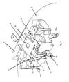
- FIG. 1 shows a cross-sectional view of the base construction 1 according to the principles of the present invention, which offers a peripheral view of a framework construction 2, which in the present embodiment is made of a suitable type of plastic.
- the hot plate 3 has been given an eccentric position in the base construction 1, thus facilitating better use of the space available on the underside of the hot plate 3, where the contactor 4 is also positioned immediately where the hot plate has its maximum elevation, i.e. the place of the hot plate 3 which is first to be exposed in the event of the water evaporating.
- the base construction has a downward-turned flange 5, the internal diameter of which is slightly smaller than the outer diameter of the hot plate 3. This ensures that the hot plate 3 cannot be accidentally sucked up into the closed container in the event of a powerful vacuum.
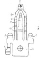
- the U-shaped seal 6 (depicted in FIG. 2), which is held inside the flange 5 by means of a clamping ring 7.
- a clamping ring 7 In the space between the clamping ring 7 and the cylindrically upright part 8 of the flange, a locking ring 9 can be seen.
- This locking ring 9 is wedged in such a manner as to squeeze the clamping ring 7 down towards the U-shaped seal 6.
- the U-shaped seal in FIG. 2 is designed with pins which are in contact with separate sides of the hot plate 3.
- the U-yoke which in the present embodiment tapers slightly towards the flange 5, will provide a seal both axially and radially when placed in the flange 5, and when the clamping ring 7 is subsequently mounted.
- the contactor 4 which has been placed in the area of the base construction which offers the most space after assembly.
- the contactor 4 which is a modified standard model featuring bimetal contacts (not shown), is inserted between the wiring for the external power supply and the regulator circuits, thus ensuring simple yet reliable assembly and contact between the power supply and the three circuits of the hot plate.
- the contactor 4 is mounted on the side of the hot plate which also features the heating circuit (not shown).
- the contact pins 10a also serve to fasten the contactor 4.
- a third contact pin 10 is folded from a standard metal sheet, which is punched out as depicted in FIG. 4.
- the third contact pin 10 comprises a guide tongue 11, which serves to guide the contact pin 10, as well as tongue pieces and locking hooks 12, which when suitably folded can lock the third contact pin 10 in the grooves present in the contactor 4.
- the spring pins 13 extend with several successive folds 14 from the guide tongue 11 to the contact point on the hot plate 3. The objective of these folds is to ensure that the third contact pin 10 moves only at a right angle to the hot plate 3. thus providing frictionless and effective contact at the contact point 16, without causing any wear.
- a supply contact 15 runs along the guide tongue 11 to the low-power circuit. This establishes an electric connection between the external supply circuit and the low-power circuit.
- FIG. 5 features a cross-sectional outline through a coffee-making apparatus fitted with a base construction according to the principles of the present invention. It will appear that the sloping position of the base helps to ensure partly that the hot plate 3 does not suddenly boil dry, and partly that the total volume of water does not evaporate during boiling, insofar as the lower, remaining volume of water cannot be heated by means of the hot plate 3. This small remaining volume of water ensures that the temperature will always be 100° C or slightly lower when boiling is complete, thus keeping the coffee beverage returning through the filter and funnel to the closed container from becoming overheated.
Landscapes
- Physics & Mathematics (AREA)
- Thermal Sciences (AREA)
- Engineering & Computer Science (AREA)
- Food Science & Technology (AREA)
- Apparatus For Making Beverages (AREA)
- Tea And Coffee (AREA)
- Sewage (AREA)
- Nitrogen And Oxygen Or Sulfur-Condensed Heterocyclic Ring Systems (AREA)
- Investigation Of Foundation Soil And Reinforcement Of Foundation Soil By Compacting Or Drainage (AREA)
Abstract
Description
- FIG. 1
- depicts a cross-sectional view of the base construction according to the principles of the present invention;
- FIG. 2
- depicts a cross-section of the U-shaped seal for the hot plate prior to mounting in the base construction;
- FIG. 3
- shows a perspective representation of the hot plate at the regulator circuit, with the third contact fastened on the upward-facing side of the Figure;
- FIG. 4
- shows a representation of the third contact pin prior to folding; and
- FIG. 5
- is a cross-sectional outline through a coffee-making apparatus fitted with a base construction according to the principles of the present invention.
Claims (10)
- A base construction (1) comprising a hot plate and an internal bottom for a coffee-making apparatus of the type designed to have water brought to a boil in a closed container (1), whereupon the water is pressed through a riser pipe (12) into a funnel, where boiling water extracts aromas and flavour from the ground coffee, whereupon the finished coffee beverage is filtered back into the closed container (1) through a filter placed at the outlet of the funnel, characterised in that the hot plate (3) and the internal bottom of the closed container are positioned so that a normal to the hot plate and/or the internal bottom is at no point vertical during boiling.
- Base construction according to claim 1, characterised in that the hot plate has been sealed towards a radial protrusion, which forms a flange (5) in the bottom, by means of a U-shaped seal (6) where the points of the U are positioned on separate sides of the hot plate, and where the U-shaped seal is fastened in the flange by means of a clamping ring (7) which squeezes the seal to the protrusion.
- Base construction according to claim 2, characterised in that a locking ring (9) is inserted between the clamping ring and the cylindrically upright part of the flange with a view to ensuring that the clamping ring is not loosened.
- Base construction according to claim 2 and/or 3, characterised in that the outer surface of the U-yoke is faintly arrow-shaped, with the greatest thickness outside the edge of the hot plate.
- Base construction according to any of the previous claims, characterised in that the hot plate (3) is fastened in an eccentric position on the inside of the base.
- Base construction according to claim 5, characterised in that the hot plate (3) is fastened on the inside of the base in a position near the highest part of this base.
- Base construction according to claim 5 and/or 6, characterised in that the thermo-sensor monitoring whether the hot plate boils dry should be placed in the area of the hot plate which is first exposed in the event of the water boiling away.
- Base construction according to any of the previous claims, characterised in that the hot plate (3) has in a known manner been fitted with a contactor (4), which has been fitted with an additional contact pin (10) with a view to the low-power circuit.
- Base construction according to claim 8, characterised in that the contact pin (10) is fastened to the contactor (4) by means of a guide tongue (11) and a number of tongue pieces and locking hooks (12).
- Base construction according to claim 8 and/or 9, characterised in that the contact pin (10) has been fitted with an external supply contact (15) and a pair of spring pins (13).
Priority Applications (1)
| Application Number | Priority Date | Filing Date | Title |
|---|---|---|---|
| SI200030159T SI1237450T1 (en) | 1999-12-16 | 2000-12-08 | Base construction for a coffee-making apparatus |
Applications Claiming Priority (3)
| Application Number | Priority Date | Filing Date | Title |
|---|---|---|---|
| DK180499 | 1999-12-16 | ||
| DK199901804A DK199901804A (en) | 1999-12-16 | 1999-12-16 | Bottom construction for a coffee maker |
| PCT/DK2000/000680 WO2001043609A1 (en) | 1999-12-16 | 2000-12-08 | Base construction for a coffee-making apparatus |
Publications (2)
| Publication Number | Publication Date |
|---|---|
| EP1237450A1 EP1237450A1 (en) | 2002-09-11 |
| EP1237450B1 true EP1237450B1 (en) | 2003-05-28 |
Family
ID=8108177
Family Applications (1)
| Application Number | Title | Priority Date | Filing Date |
|---|---|---|---|
| EP00981183A Expired - Lifetime EP1237450B1 (en) | 1999-12-16 | 2000-12-08 | Base construction for a coffee-making apparatus |
Country Status (15)
| Country | Link |
|---|---|
| US (1) | US6340808B2 (en) |
| EP (1) | EP1237450B1 (en) |
| JP (1) | JP2003516790A (en) |
| CN (1) | CN1183868C (en) |
| AT (1) | ATE241309T1 (en) |
| AU (1) | AU775424B2 (en) |
| CA (1) | CA2394065C (en) |
| DE (1) | DE60003080T2 (en) |
| DK (2) | DK199901804A (en) |
| ES (1) | ES2195947T3 (en) |
| HK (1) | HK1046831A1 (en) |
| NO (1) | NO321970B1 (en) |
| PT (1) | PT1237450E (en) |
| TW (1) | TW575414B (en) |
| WO (1) | WO2001043609A1 (en) |
Cited By (1)
| Publication number | Priority date | Publication date | Assignee | Title |
|---|---|---|---|---|
| US9232873B2 (en) | 2013-06-03 | 2016-01-12 | Starbucks Corporation | Method for brewing a beverage |
Families Citing this family (4)
| Publication number | Priority date | Publication date | Assignee | Title |
|---|---|---|---|---|
| GB0103658D0 (en) * | 2001-02-14 | 2001-03-28 | Strix Ltd | Electric beverage maker |
| DE60326972D1 (en) | 2002-09-27 | 2009-05-14 | Koninkl Philips Electronics Nv | APPARATUS FOR COFFEE PREPARATION |
| US20050109762A1 (en) * | 2002-12-31 | 2005-05-26 | Rice John M. | Coffee saver |
| CN104116408B (en) | 2014-07-18 | 2017-02-01 | 允慧科技(上海)有限公司 | Air lift pumping device, fluid container comprising air lift pumping device, and tea making machine |
Family Cites Families (9)
| Publication number | Priority date | Publication date | Assignee | Title |
|---|---|---|---|---|
| US2690709A (en) * | 1948-10-08 | 1954-10-05 | Arvin Ind Inc | Electric coffee maker |
| US3224360A (en) * | 1961-06-14 | 1965-12-21 | Sunbeam Corp | Automatic coffee maker |
| DE3861394D1 (en) * | 1987-02-18 | 1991-02-07 | Sharp Kk | VACUUM COFFEE MAKER. |
| DE3717678A1 (en) * | 1987-05-26 | 1988-12-08 | Krups Stiftung | HOUSEHOLD APPLIANCE FOR PREPARING TEA |
| JPH0196132U (en) * | 1987-12-18 | 1989-06-26 | ||
| DE3928475C1 (en) * | 1989-08-29 | 1991-05-29 | Robert Krups Gmbh & Co Kg, 5650 Solingen, De | |
| US5699718A (en) * | 1996-08-22 | 1997-12-23 | Chiaphua Industries Limited | Coffee making machines |
| US5782163A (en) * | 1996-12-26 | 1998-07-21 | Chang; Kwei-Tang | Coffee maker |
| ES2173539T3 (en) * | 1998-11-25 | 2002-10-16 | Pi Design Ag | DEVICE FOR THE PREPARATION OF HOT BEVERAGES AND METHOD FOR THE PREPARATION OF HOT BEVERAGES USING THE MENTIONED DEVICE. |
-
1999
- 1999-12-16 DK DK199901804A patent/DK199901804A/en not_active Application Discontinuation
-
2000
- 2000-12-08 ES ES00981183T patent/ES2195947T3/en not_active Expired - Lifetime
- 2000-12-08 CN CNB00817122XA patent/CN1183868C/en not_active Expired - Fee Related
- 2000-12-08 CA CA002394065A patent/CA2394065C/en not_active Expired - Fee Related
- 2000-12-08 JP JP2001544555A patent/JP2003516790A/en active Pending
- 2000-12-08 DE DE60003080T patent/DE60003080T2/en not_active Expired - Fee Related
- 2000-12-08 WO PCT/DK2000/000680 patent/WO2001043609A1/en not_active Ceased
- 2000-12-08 HK HK02107884.2A patent/HK1046831A1/en unknown
- 2000-12-08 AU AU18520/01A patent/AU775424B2/en not_active Ceased
- 2000-12-08 EP EP00981183A patent/EP1237450B1/en not_active Expired - Lifetime
- 2000-12-08 AT AT00981183T patent/ATE241309T1/en not_active IP Right Cessation
- 2000-12-08 PT PT00981183T patent/PT1237450E/en unknown
- 2000-12-08 DK DK00981183T patent/DK1237450T3/en active
- 2000-12-15 US US09/736,173 patent/US6340808B2/en not_active Expired - Fee Related
- 2000-12-16 TW TW89127018A patent/TW575414B/en not_active IP Right Cessation
-
2002
- 2002-06-07 NO NO20022704A patent/NO321970B1/en unknown
Cited By (1)
| Publication number | Priority date | Publication date | Assignee | Title |
|---|---|---|---|---|
| US9232873B2 (en) | 2013-06-03 | 2016-01-12 | Starbucks Corporation | Method for brewing a beverage |
Also Published As
| Publication number | Publication date |
|---|---|
| AU775424B2 (en) | 2004-07-29 |
| NO321970B1 (en) | 2006-07-31 |
| CN1183868C (en) | 2005-01-12 |
| ATE241309T1 (en) | 2003-06-15 |
| DE60003080D1 (en) | 2003-07-03 |
| DE60003080T2 (en) | 2003-12-04 |
| JP2003516790A (en) | 2003-05-20 |
| NO20022704L (en) | 2002-07-04 |
| AU1852001A (en) | 2001-06-25 |
| WO2001043609A1 (en) | 2001-06-21 |
| HK1046831A1 (en) | 2003-01-30 |
| CN1409616A (en) | 2003-04-09 |
| CA2394065C (en) | 2006-08-15 |
| WO2001043609B1 (en) | 2001-11-15 |
| DK199901804A (en) | 2001-06-17 |
| ES2195947T3 (en) | 2003-12-16 |
| DK1237450T3 (en) | 2003-09-01 |
| PT1237450E (en) | 2003-09-30 |
| US20010004070A1 (en) | 2001-06-21 |
| EP1237450A1 (en) | 2002-09-11 |
| NO20022704D0 (en) | 2002-06-07 |
| CA2394065A1 (en) | 2001-06-21 |
| US6340808B2 (en) | 2002-01-22 |
| TW575414B (en) | 2004-02-11 |
Similar Documents
| Publication | Publication Date | Title |
|---|---|---|
| JP3415818B2 (en) | Home water bath with steaming function and method for producing red ginseng extract using the same | |
| US20150359377A1 (en) | Single Cup Beverage Maker and Method of Using Same | |
| FR2822362A1 (en) | Automatic French press beverage maker for e.g. coffee, has carafe with plunger and strainer which are arranged for manually separating infused beverage from beverage making material | |
| US7084375B2 (en) | Cookpot | |
| EP1237450B1 (en) | Base construction for a coffee-making apparatus | |
| EP1658796A3 (en) | Coffee machine and method for producing a hot drink | |
| WO2008076869A3 (en) | Apparatus and method for brewing coffee, tea and espresso | |
| PL1658795T3 (en) | Coffee machine and method for producing a hot drink | |
| EP1632157A1 (en) | A jug, an electrothermal jug and an electrothermal jug without wire for cooking beverage | |
| CN211155317U (en) | Air fryer | |
| CN104490274B (en) | Split type coffee machine | |
| UY23638A1 (en) | FOOD PRODUCT BASED ON SOY BEANS AND ITS OBTAINING PROCEDURE. | |
| CN107713844A (en) | Coffee electric cooker | |
| JPH0122588Y2 (en) | ||
| GB2290945A (en) | A kettle | |
| US20170251867A1 (en) | Dual-circuit coffee maker apparatus | |
| KR200365887Y1 (en) | A coffee machine | |
| KR200335063Y1 (en) | cook-pot for not overflow | |
| KR20200058144A (en) | Structure of grill for under rage | |
| CN2469844Y (en) | Pressure health care cooking vessel | |
| JPS61164530A (en) | Hot water feeder | |
| KR20050035658A (en) | A coffee machine | |
| RU93049268A (en) | FOOD PRODUCT ON THE BASIS OF SOYA BEANS AND THE METHOD OF ITS OBTAINING | |
| CA2036530A1 (en) | Vegetable steamer | |
| TWM243156U (en) | Steamer |
Legal Events
| Date | Code | Title | Description |
|---|---|---|---|
| PUAI | Public reference made under article 153(3) epc to a published international application that has entered the european phase |
Free format text: ORIGINAL CODE: 0009012 |
|
| 17P | Request for examination filed |
Effective date: 20020606 |
|
| AK | Designated contracting states |
Kind code of ref document: A1 Designated state(s): AT BE CH CY DE DK ES FI FR GB GR IE IT LI LU MC NL PT SE TR |
|
| AX | Request for extension of the european patent |
Free format text: AL PAYMENT 20020606;LT PAYMENT 20020606;LV PAYMENT 20020606;MK PAYMENT 20020606;RO PAYMENT 20020606;SI PAYMENT 20020606 |
|
| GRAH | Despatch of communication of intention to grant a patent |
Free format text: ORIGINAL CODE: EPIDOS IGRA |
|
| GRAH | Despatch of communication of intention to grant a patent |
Free format text: ORIGINAL CODE: EPIDOS IGRA |
|
| GRAA | (expected) grant |
Free format text: ORIGINAL CODE: 0009210 |
|
| AK | Designated contracting states |
Designated state(s): AT BE CH CY DE DK ES FI FR GB GR IE IT LI LU MC NL PT SE TR |
|
| AX | Request for extension of the european patent |
Extension state: AL LT LV MK RO SI |
|
| REG | Reference to a national code |
Ref country code: GB Ref legal event code: FG4D |
|
| REG | Reference to a national code |
Ref country code: CH Ref legal event code: EP |
|
| REG | Reference to a national code |
Ref country code: IE Ref legal event code: FG4D |
|
| REG | Reference to a national code |
Ref country code: CH Ref legal event code: NV Representative=s name: ISLER & PEDRAZZINI AG |
|
| REF | Corresponds to: |
Ref document number: 60003080 Country of ref document: DE Date of ref document: 20030703 Kind code of ref document: P |
|
| REG | Reference to a national code |
Ref country code: SE Ref legal event code: TRGR |
|
| REG | Reference to a national code |
Ref country code: DK Ref legal event code: T3 |
|
| REG | Reference to a national code |
Ref country code: GR Ref legal event code: EP Ref document number: 20030402904 Country of ref document: GR |
|
| REG | Reference to a national code |
Ref country code: PT Ref legal event code: SC4A Free format text: AVAILABILITY OF NATIONAL TRANSLATION Effective date: 20030807 |
|
| REG | Reference to a national code |
Ref country code: ES Ref legal event code: FG2A Ref document number: 2195947 Country of ref document: ES Kind code of ref document: T3 |
|
| ET | Fr: translation filed | ||
| PLBE | No opposition filed within time limit |
Free format text: ORIGINAL CODE: 0009261 |
|
| STAA | Information on the status of an ep patent application or granted ep patent |
Free format text: STATUS: NO OPPOSITION FILED WITHIN TIME LIMIT |
|
| 26N | No opposition filed |
Effective date: 20040302 |
|
| REG | Reference to a national code |
Ref country code: SI Ref legal event code: IF |
|
| REG | Reference to a national code |
Ref country code: CH Ref legal event code: PCAR Free format text: ISLER & PEDRAZZINI AG;POSTFACH 1772;8027 ZUERICH (CH) |
|
| PGFP | Annual fee paid to national office [announced via postgrant information from national office to epo] |
Ref country code: DK Payment date: 20071227 Year of fee payment: 8 Ref country code: ES Payment date: 20071219 Year of fee payment: 8 Ref country code: LU Payment date: 20071227 Year of fee payment: 8 Ref country code: MC Payment date: 20071116 Year of fee payment: 8 Ref country code: NL Payment date: 20071219 Year of fee payment: 8 |
|
| PGFP | Annual fee paid to national office [announced via postgrant information from national office to epo] |
Ref country code: CH Payment date: 20071214 Year of fee payment: 8 Ref country code: FI Payment date: 20071217 Year of fee payment: 8 Ref country code: AT Payment date: 20071220 Year of fee payment: 8 |
|
| PGFP | Annual fee paid to national office [announced via postgrant information from national office to epo] |
Ref country code: BE Payment date: 20071219 Year of fee payment: 8 |
|
| PGFP | Annual fee paid to national office [announced via postgrant information from national office to epo] |
Ref country code: FR Payment date: 20071130 Year of fee payment: 8 Ref country code: GB Payment date: 20071219 Year of fee payment: 8 |
|
| PGFP | Annual fee paid to national office [announced via postgrant information from national office to epo] |
Ref country code: CY Payment date: 20071127 Year of fee payment: 8 Ref country code: DE Payment date: 20071220 Year of fee payment: 8 Ref country code: GR Payment date: 20071224 Year of fee payment: 8 Ref country code: IT Payment date: 20071229 Year of fee payment: 8 Ref country code: SE Payment date: 20071221 Year of fee payment: 8 |
|
| PGFP | Annual fee paid to national office [announced via postgrant information from national office to epo] |
Ref country code: TR Payment date: 20071203 Year of fee payment: 8 |
|
| PGFP | Annual fee paid to national office [announced via postgrant information from national office to epo] |
Ref country code: PT Payment date: 20081118 Year of fee payment: 9 |
|
| BERE | Be: lapsed |
Owner name: *PI-DESIGN A.G. Effective date: 20081231 |
|
| REG | Reference to a national code |
Ref country code: HK Ref legal event code: WD Ref document number: 1046831 Country of ref document: HK |
|
| PG25 | Lapsed in a contracting state [announced via postgrant information from national office to epo] |
Ref country code: MC Free format text: LAPSE BECAUSE OF NON-PAYMENT OF DUE FEES Effective date: 20081231 Ref country code: FI Free format text: LAPSE BECAUSE OF NON-PAYMENT OF DUE FEES Effective date: 20081208 |
|
| REG | Reference to a national code |
Ref country code: CH Ref legal event code: PL |
|
| REG | Reference to a national code |
Ref country code: DK Ref legal event code: EBP |
|
| EUG | Se: european patent has lapsed | ||
| GBPC | Gb: european patent ceased through non-payment of renewal fee |
Effective date: 20081208 |
|
| PG25 | Lapsed in a contracting state [announced via postgrant information from national office to epo] |
Ref country code: AT Free format text: LAPSE BECAUSE OF NON-PAYMENT OF DUE FEES Effective date: 20081208 |
|
| PGFP | Annual fee paid to national office [announced via postgrant information from national office to epo] |
Ref country code: IE Payment date: 20071217 Year of fee payment: 8 |
|
| NLV4 | Nl: lapsed or anulled due to non-payment of the annual fee |
Effective date: 20090701 |
|
| REG | Reference to a national code |
Ref country code: IE Ref legal event code: MM4A |
|
| PG25 | Lapsed in a contracting state [announced via postgrant information from national office to epo] |
Ref country code: BE Free format text: LAPSE BECAUSE OF NON-PAYMENT OF DUE FEES Effective date: 20081231 |
|
| REG | Reference to a national code |
Ref country code: FR Ref legal event code: ST Effective date: 20090831 |
|
| PG25 | Lapsed in a contracting state [announced via postgrant information from national office to epo] |
Ref country code: LI Free format text: LAPSE BECAUSE OF NON-PAYMENT OF DUE FEES Effective date: 20081231 Ref country code: CY Free format text: LAPSE BECAUSE OF NON-PAYMENT OF DUE FEES Effective date: 20081208 Ref country code: IE Free format text: LAPSE BECAUSE OF NON-PAYMENT OF DUE FEES Effective date: 20081208 Ref country code: DE Free format text: LAPSE BECAUSE OF NON-PAYMENT OF DUE FEES Effective date: 20090701 Ref country code: CH Free format text: LAPSE BECAUSE OF NON-PAYMENT OF DUE FEES Effective date: 20081231 |
|
| REG | Reference to a national code |
Ref country code: SI Ref legal event code: KO00 Effective date: 20090717 |
|
| PG25 | Lapsed in a contracting state [announced via postgrant information from national office to epo] |
Ref country code: NL Free format text: LAPSE BECAUSE OF NON-PAYMENT OF DUE FEES Effective date: 20090701 Ref country code: GB Free format text: LAPSE BECAUSE OF NON-PAYMENT OF DUE FEES Effective date: 20081208 |
|
| PG25 | Lapsed in a contracting state [announced via postgrant information from national office to epo] |
Ref country code: DK Free format text: LAPSE BECAUSE OF NON-PAYMENT OF DUE FEES Effective date: 20090105 |
|
| PG25 | Lapsed in a contracting state [announced via postgrant information from national office to epo] |
Ref country code: GR Free format text: LAPSE BECAUSE OF NON-PAYMENT OF DUE FEES Effective date: 20090703 |
|
| REG | Reference to a national code |
Ref country code: ES Ref legal event code: FD2A Effective date: 20081209 |
|
| PG25 | Lapsed in a contracting state [announced via postgrant information from national office to epo] |
Ref country code: FR Free format text: LAPSE BECAUSE OF NON-PAYMENT OF DUE FEES Effective date: 20081231 Ref country code: ES Free format text: LAPSE BECAUSE OF NON-PAYMENT OF DUE FEES Effective date: 20081209 |
|
| REG | Reference to a national code |
Ref country code: PT Ref legal event code: MM4A Free format text: LAPSE DUE TO NON-PAYMENT OF FEES Effective date: 20100608 |
|
| PG25 | Lapsed in a contracting state [announced via postgrant information from national office to epo] |
Ref country code: SE Free format text: LAPSE BECAUSE OF NON-PAYMENT OF DUE FEES Effective date: 20081209 Ref country code: LU Free format text: LAPSE BECAUSE OF NON-PAYMENT OF DUE FEES Effective date: 20081208 Ref country code: PT Free format text: LAPSE BECAUSE OF NON-PAYMENT OF DUE FEES Effective date: 20100608 |
|
| PG25 | Lapsed in a contracting state [announced via postgrant information from national office to epo] |
Ref country code: TR Free format text: LAPSE BECAUSE OF NON-PAYMENT OF DUE FEES Effective date: 20100928 |
|
| PG25 | Lapsed in a contracting state [announced via postgrant information from national office to epo] |
Ref country code: TR Free format text: LAPSE BECAUSE OF NON-PAYMENT OF DUE FEES Effective date: 20081208 |
|
| PG25 | Lapsed in a contracting state [announced via postgrant information from national office to epo] |
Ref country code: IT Free format text: LAPSE BECAUSE OF NON-PAYMENT OF DUE FEES Effective date: 20081208 |