EP1237286A1 - Wireless communication device - Google Patents
Wireless communication device Download PDFInfo
- Publication number
- EP1237286A1 EP1237286A1 EP00964669A EP00964669A EP1237286A1 EP 1237286 A1 EP1237286 A1 EP 1237286A1 EP 00964669 A EP00964669 A EP 00964669A EP 00964669 A EP00964669 A EP 00964669A EP 1237286 A1 EP1237286 A1 EP 1237286A1
- Authority
- EP
- European Patent Office
- Prior art keywords
- radio communication
- communication device
- usage mode
- unit
- output
- Prior art date
- Legal status (The legal status is an assumption and is not a legal conclusion. Google has not performed a legal analysis and makes no representation as to the accuracy of the status listed.)
- Withdrawn
Links
Images


Classifications
-
- H—ELECTRICITY
- H04—ELECTRIC COMMUNICATION TECHNIQUE
- H04B—TRANSMISSION
- H04B1/00—Details of transmission systems, not covered by a single one of groups H04B3/00 - H04B13/00; Details of transmission systems not characterised by the medium used for transmission
- H04B1/38—Transceivers, i.e. devices in which transmitter and receiver form a structural unit and in which at least one part is used for functions of transmitting and receiving
- H04B1/40—Circuits
- H04B1/401—Circuits for selecting or indicating operating mode
-
- H—ELECTRICITY
- H04—ELECTRIC COMMUNICATION TECHNIQUE
- H04M—TELEPHONIC COMMUNICATION
- H04M1/00—Substation equipment, e.g. for use by subscribers
- H04M1/72—Mobile telephones; Cordless telephones, i.e. devices for establishing wireless links to base stations without route selection
- H04M1/724—User interfaces specially adapted for cordless or mobile telephones
- H04M1/72403—User interfaces specially adapted for cordless or mobile telephones with means for local support of applications that increase the functionality
- H04M1/72409—User interfaces specially adapted for cordless or mobile telephones with means for local support of applications that increase the functionality by interfacing with external accessories
-
- H—ELECTRICITY
- H04—ELECTRIC COMMUNICATION TECHNIQUE
- H04W—WIRELESS COMMUNICATION NETWORKS
- H04W52/00—Power management, e.g. Transmission Power Control [TPC] or power classes
- H04W52/04—Transmission power control [TPC]
- H04W52/18—TPC being performed according to specific parameters
- H04W52/22—TPC being performed according to specific parameters taking into account previous information or commands
- H04W52/226—TPC being performed according to specific parameters taking into account previous information or commands using past references to control power, e.g. look-up-table
-
- H—ELECTRICITY
- H04—ELECTRIC COMMUNICATION TECHNIQUE
- H04W—WIRELESS COMMUNICATION NETWORKS
- H04W52/00—Power management, e.g. Transmission Power Control [TPC] or power classes
- H04W52/04—Transmission power control [TPC]
- H04W52/18—TPC being performed according to specific parameters
- H04W52/28—TPC being performed according to specific parameters using user profile, e.g. mobile speed, priority or network state, e.g. standby, idle or non-transmission
- H04W52/287—TPC being performed according to specific parameters using user profile, e.g. mobile speed, priority or network state, e.g. standby, idle or non-transmission when the channel is in stand-by
-
- H—ELECTRICITY
- H04—ELECTRIC COMMUNICATION TECHNIQUE
- H04W—WIRELESS COMMUNICATION NETWORKS
- H04W52/00—Power management, e.g. Transmission Power Control [TPC] or power classes
- H04W52/04—Transmission power control [TPC]
- H04W52/18—TPC being performed according to specific parameters
- H04W52/28—TPC being performed according to specific parameters using user profile, e.g. mobile speed, priority or network state, e.g. standby, idle or non-transmission
- H04W52/288—TPC being performed according to specific parameters using user profile, e.g. mobile speed, priority or network state, e.g. standby, idle or non-transmission taking into account the usage mode, e.g. hands-free, data transmission or telephone
-
- H—ELECTRICITY
- H04—ELECTRIC COMMUNICATION TECHNIQUE
- H04M—TELEPHONIC COMMUNICATION
- H04M2250/00—Details of telephonic subscriber devices
- H04M2250/12—Details of telephonic subscriber devices including a sensor for measuring a physical value, e.g. temperature or motion
Definitions
- the present invention relates to a radio communication device and, more particularly, to a radio communication device capable of transmitting an optimum radio output in accordance with a usage mode.
- a booster radio output amplifier
- a portable telephone Conventionally, a booster (radio output amplifier) is generally connected to a portable telephone to enhance a radio output.
- a radio communication device disclosed in Japanese Patent Laying-Open No. 8-65365 includes a portable telephone 116 and a booster 117 connected to each other via an RF (Radio Frequency) signal line 118 and a control signal line 119.
- RF Radio Frequency
- Portable telephone 116 includes an antenna 5, a transmission circuit 2 for transmitting an output signal, an output control circuit 4 for controlling an output of transmission circuit 2, a switch 120 connected to transmission circuit 2, for receiving the output signal of the transmission circuit 2 as an input and leading the output signal to booster 117 via RF signal line 118 or to antenna 5 on the basis of a selection signal from a control circuit to be described hereinafter, and a control circuit 103 connected to output control circuit 4 and the switch 120, for controlling output control circuit 4 and supplying the selection signal to switch 120.
- Control circuit 103 includes an amplification level storing device 121, a maximum transmission output storing device 122, a connection detecting circuit 123, and a CPU (Central Processing Unit) 107.
- amplification level storing device 121 includes an amplification level storing device 121, a maximum transmission output storing device 122, a connection detecting circuit 123, and a CPU (Central Processing Unit) 107.
- CPU Central Processing Unit
- Booster 117 includes an output amplifying circuit 124 for amplifying an output signal received from portable telephone 116 via RF signal line 118, an output control circuit 125 connected to output amplifying circuit 124, for controlling an output from the output amplifying circuit, an antenna 127 connected to output amplifying circuit 124, and a control circuit 126 connected to control signal line 119 and output control circuit 125, for controlling output control circuit 125.
- Control circuit 126 includes an amplification level storing device 128 and a CPU 129 connected to amplification level storing device 128.
- booster 117 When booster 117 is connected to portable telephone 116, the connection of booster 117 is detected by connection detecting circuit 123 in portable telephone 116.
- CPU 107 in portable telephone 116 information indicating whether portable telephone 116 is in a call mode or a standby mode is stored. According to the information, CPU 107 determines whether portable telephone 116 is in the call mode or standby mode at the time when booster 117 is connected to portable telephone 116.
- control circuit 103 controls switch 120 to switch the direction of the radio signal from antenna 5 of the portable telephone to RF signal line 118.
- the radio signal is supplied to output amplifying circuit 124 in booster via RF signal line 118.
- control circuit 126 in booster 117 When control circuit 126 in booster 117 receives information that portable telephone 116 and booster 117 are connected to each other during a call from portable telephone 116 via control signal line 119, control circuit 126 notifies CPU 129 of the information. Further, when control circuit 126 receives the amplification level information from portable telephone 116, control circuit 126 stores the information into amplification level storing device 128. On the basis of the amplification level information stored in amplification level storing device 128, CPU 129 controls output amplifying circuit 124 via output control circuit 125. Output amplifying circuit 124 transmits the amplified output signal from antenna 127.
- a radio output control for controlling an output so as to not exceed a maximum transmission output which is set at the time of start of a call even when portable telephone 116 is connected to booster 117 during a call can be realized. That is, in the radio communication device, according to a mechanical difference whether antenna 5 of portable telephone 116 is used or antenna 127 of booster 117 is used, the maximum transmission output value of an output signal is adjusted.
- the present invention has been achieved to solve the problem and its object is to provide a radio communication device capable of changing an output signal to a proper transmission output value in accordance with a usage mode.
- Another object of the invention is to provide a radio communication device capable of automatically detecting the usage mode and changing an output signal to a proper transmission output value.
- a radio communication device includes: a storing unit for storing a plurality of maximum transmission outputs corresponding to a plurality of predetermined usage modes, a usage mode detecting unit for detecting a usage mode, a maximum transmission output determining unit connected to the usage mode detecting unit and the storing unit, for determining a maximum transmission output on the basis of a detection result of the usage mode detecting unit, a transmission circuit for transmitting a signal to the outside, and an output control circuit connected to the maximum transmission output determining unit and the transmission circuit, for controlling a transmission output from the transmission circuit on the basis of the maximum transmission output.
- a usage mode is detected by the usage mode detecting unit, and the maximum transmission output is determined on the basis of the usage mode. Consequently, according to the usage mode, the output signal can be changed to a proper transmission output value.
- the usage mode detecting unit detects a usage mode at the time of receiving an incoming call or originating a call. Only at the time of receiving an incoming call or at the time of originating a call, the usage mode is detected. Consequently, in the case where the usage mode is not changed during communication, the number of processes of the usage mode detecting unit can be minimized.
- the usage mode detecting unit detects the usage mode at turn-on of the radio communication device.
- the usage mode is detected only at turn-on. Consequently, in the case of a radio communication device in which the usage mode is not changed after turn-on, the number of processes of the usage mode detecting unit can be minimized.
- the usage mode detecting unit includes a temperature measuring unit for measuring temperature of the periphery of the radio communication device, and a detecting circuit connected to the temperature measuring unit, for detecting a usage mode on the basis of an output result of the temperature measuring unit.
- a temperature measuring unit for measuring temperature of the periphery of the radio communication device
- a detecting circuit connected to the temperature measuring unit, for detecting a usage mode on the basis of an output result of the temperature measuring unit.
- the usage mode detecting unit includes a distance measuring unit for measuring a distance from the radio communication device to an obstacle, and a detecting circuit connected to the distance measuring unit, for detecting the usage mode on the basis of an output result of the distance measuring unit.
- a distance measuring unit for measuring a distance from the radio communication device to an obstacle
- a detecting circuit connected to the distance measuring unit, for detecting the usage mode on the basis of an output result of the distance measuring unit.
- the usage mode detecting unit includes an amplitude measuring unit for measuring amplitude of oscillation of the radio communication device, and a detecting circuit connected to the amplitude measuring unit, for detecting a usage mode on the basis of an output result of the amplitude measuring unit.
- the oscillation of the radio communication device changes according to the usage mode, by measuring the amplitude of oscillation of the radio communication device, the usage mode is detected, and an output signal can be changed to a proper transmission output value.
- the usage mode detecting unit includes a tilt measuring unit for measuring a tilt of the radio communication device, and a detecting circuit connected to the tilt measuring unit, for detecting a usage mode on the basis of an output result of the tilt measuring unit.
- the tilt of the radio communication device changes according to the usage mode, by measuring the tilt of the radio communication device, the usage mode is detected, and an output signal can be changed to a proper transmission output value.
- the usage mode detecting unit includes an operation unit for receiving an operation on the radio communication device, and a detecting circuit connected to the operation unit, for detecting a usage mode on the basis of an output result of the operation unit.
- the usage mode is determined by an operating method particular to the user, by analyzing the operation of the user, the usage mode is detected, and an output signal can be changed to a proper transmission output value.
- the usage mode detecting unit includes an amplitude measuring unit for measuring amplitude of oscillation of the radio communication device, a tilt measuring unit for measuring a tilt of the radio communication unit, and a detecting circuit connected to the amplitude measuring unit and the tilt measuring unit, for detecting a usage mode on the basis of output results of the amplitude measuring unit and the tilt measuring unit.
- the usage mode is detected, and an output signal can be changed to a proper transmission output value.
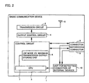
- a radio communication device 1 includes an antenna 5, a transmission circuit 2 connected to antenna 5, for transmitting an output signal from antenna 5, an output control circuit 4 connected to transmission circuit 2, for controlling an output of transmission circuit 2, two connectors 8 and 9, a unit 10 for detecting connection of an external device or the like, which detects whether or not an external device or the like is connected to connector 8 or 9, and a control circuit 3 connected to connectors 8 and 9, unit 10 for detecting connection of an external device, and output control circuit 4, for controlling output control circuit 4 in accordance with an output of unit 10 for detecting connection of an external device.
- Control circuit 3 includes a usage mode vs. maximum transmission output storing unit 6 for storing a plurality of maximum transmission outputs determined according to a plurality of usage modes of radio communication device 1, and a CPU 7 connected to usage mode vs. maximum transmission output storing unit 6 and unit 10 for detecting connection of an external device, for controlling output control circuit 4 by executing processes of a flow chart which will be described hereinafter in accordance with an output of unit 10 for detecting connection of an external device.
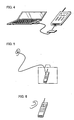
- radio communication device 1 operate as follows. It is assumed here that there are total three usage modes of the radio communication device 1; a mode of using radio communication device 1 on a desk as shown in Fig. 4, a mode of using radio communication device 1 in a bag as shown in Fig. 5, and a mode of using radio communication device 1 by being applied to an ear of the user as shown in Fig. 6.
- radio communication device 1 two connectors 8 and 9 exist. In the case where an external device or the like is connected to connector 8, it is determined that radio communication device 1 is used on a desk. In the case where the external device or the like is connected to connector 9, it is determined that radio communication device 1 is used in a bag. In the case where no external device is connected to any of connectors 8 and 9, it is determined that the user uses ratio communication device 1 by applying it to his/her ear.
- the correspondence relations between the connection of an external device or the like and the usage modes are stored in CPU 7. It is assumed that, for example, in usage mode vs.
- a maximum transmission output value "A” is stored in the case of the mode of using radio communication device 1 on a desk
- a maximum transmission output value "B” is stored in the case of the mode of using radio communication device 1 in a bag
- a maximum transmission output value "C” is stored in the case of the mode of using radio communication device 1 by being applied to an ear of the user.
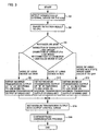
- Unit 10 for detecting connection of an external device or the like detects a connection state of an external device or the like to connector 8 or 9 (S2).
- Unit 10 for detecting connection of an external device or the like reports a detection result to CPU 7 (S3). For example, when connection of an external device or the like to connector 8 is detected, unit 10 for detecting connection of an external device or the like reports that "there is connection of an external device or the like to connector 8" to CPU 7.
- CPU 7 determines the usage mode in accordance with the report from unit 10 for detecting connection of an external device or the like (S6). For example, when it is reported that "there is connection of an external device or the like to connector 8", CPU 7 determines the mode of using radio communication device 1 on a desk.
- the relations between the connection states of connectors 8 and 9 and the modes are as described above.
- CPU 7 obtains the maximum transmission output value of "A” from usage mode vs. maximum transmission output storing unit 6 (S8).
- CPU 7 obtains the maximum transmission output value of "B" from usage mode vs. maximum transmission output storing unit 6 (S10).
- CPU 7 obtains the maximum transmission output value of "C” from user mode maximum transmission output correspondence storing unit 6 (S12).
- control circuit 3 sets the maximum transmission output value obtained by the process in any of S8 to S12 into output control circuit 4 (S14). After that, the radio communication process is continued (S16).
- the above-described process is always performed in the background or by an interrupting process using a timer separately from the communication of the radio communication device.
- the embodiment even when the usage mode is changed by connection of an external device or the like, it can be controlled so that the maximum output power from the antenna becomes the optimum value.
- the maximum output power from the antenna can be controlled to be the optimum power.
- a radio communication device has a hardware configuration similar to that of the radio communication device described by referring to Fig. 2. Consequently, the detailed description will not be repeated here.
- the process of recognizing the usage mode is always performed in the background or by the timer interrupting process.
- the process of recognizing the usage mode is performed before a response to an incoming call or before transmission of a call originating request.
- components of a radio communication device 1 operate as follows.
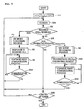
- radio communication device 1 When the power of radio communication device 1 is turned on (S22), radio communication device 1 shifts to a standby mode (S4).
- a control circuit 3 determines whether radio communication device 1 has received an incoming call or not (S26).
- the usage mode recognizing process for recognizing the usage mode of radio communication device 1 is executed (S28). The usage mode recognizing process will be described hereinafter.
- radio communication device 1 responds to the incoming call (S30) and continues the radio communicating process (S32).
- Control circuit 3 determines whether the communication has finished or not (S34). If the communication is not finished (NO in S34), the routine returns to S32. If the communication has been finished (YES in S34), the routine returns to S24 and the standby mode is set again.
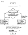
- control circuit 3 determines whether a call originating operation is performed by the user or not (S36). When it is determined that the call originating operation is performed (YES in S36), a usage mode recognizing process similar to S28 is executed (S38). After S38, a call originating request is transmitted from a transmission circuit 2 (S40). After that, the radio communication process is continued (S42). Control circuit 3 determines whether communication has been finished or not (S44). If the communication has not been finished (NO in S44), the routine returns to S42. If the communication has been finished (YES in S44), the routine returns to S24, and the standby mode is set again.
- control circuit 3 determines whether the power source of radio communication device 1 has been turned off or not (NO in S46). If the power source of radio communication device 1 has not been turned off (NO in S46), the routine returns to S24 and the standby mode is set again. If the power source of radio communication device 1 is turned off (YES in S46), the process is finished.
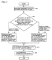
- the process is a process of recognizing the usage mode of radio communication device 1 and setting the proper maximum transmission output value into an output control circuit 4.
- the details of the process are similar to those of the processes of S6 to S14 in Fig. 3. Consequently, the detailed description will not be repeated here.
- the usage mode recognizing process is performed only before response to an incoming call or before transmission of a call originating request. Consequently, in the case of a radio communication device whose usage mode is not changed during communication, the number of times of performing the usage mode recognizing process can be reduced as compared with the first embodiment. As a result, the power consumption of the radio communication device can be reduced.
- a radio communication device according to a third embodiment. of the present invention has a hardware configuration similar to that of the radio communication device described by referring to Fig. 2. Consequently, the detailed description will not be repeated here.
- the process of recognizing the usage mode is always performed in the background or by a timer interrupting process.
- the process of recognizing the usage mode is performed at turn-on of the power source.
- components of a radio communication device 1 operate as follows.
- a usage mode recognizing process (S52) is performed.
- the usage mode recognizing process is similar to that described by referring to Fig. 8, so that its description will not be repeated here.
- radio communication device 1 shifts to a standby mode (S24).
- the processes after the shift to the standby mode are similar to those in Fig. 7 except for the usage mode recognizing process in S28 and S38. Consequently, the detailed description will not be repeated here.
- the usage mode recognizing process is performed only when the power source of radio communication device 1 is turned on. Consequently, in the case of the radio communication device whose usage mode is not changed after the turn-on of the power, the number of times of performing the usage mode recognizing process can be reduced as compared with the first and second embodiments. As a result, the power consumption of the radio communication device can be reduced.
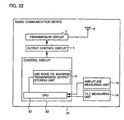
- a radio communication device 21 includes an antenna 5, a transmission circuit 2 connected to antenna 5, for transmitting an output signal from antenna 5, an output control circuit 4 connected to transmission circuit 2, for controlling an output of transmission circuit 2, a connector 8, and a control circuit 23 connected to connector 8 and output control circuit 4, for controlling output control circuit 4 on the basis of the connection state of an external device 25 or the like to connector 8.
- Control circuit 23 includes a usage mode vs. maximum transmission output storing unit 6 for storing a plurality of maximum transmission outputs which are predetermined in accordance with a plurality of usage modes of radio communication device 21, and a CPU 27 connected to usage mode vs. maximum transmission output storing unit 6 and connector 8, which executes processes according to a flow chart to be described hereinafter in accordance with the connection state of external device 25 or the like to connector 8 to thereby control output control circuit 4.
- CPU 27 performs communications with an external device or the like connected to the connector and, on the basis of the information, recognizes the usage mode of a radio communication device 21.
- radio communication device 21 operate as follows.
- radio communication device 21 when a camera unit is connected as an external device to connector 8 and radio communication device 21 is used as a TV telephone by using the camera unit, an image of the user himself/herself has to be captured by the camera. In such a case, the mode of using the radio communication device on a desk can be considered.
- the mode of using the radio communication device on a desk cannot be determined only from connection of the camera unit to connector 8, for example, in the case where the radio communication device to which the camera unit is attached is not used as a TV telephone but only voice is transmitted/received, the mode of using the radio communication device by being applied to an ear of the user is determined.
- radio communication device 21 and the camera unit are used as a TV telephone, it is necessary to capture image data from the camera unit.
- a data passing process (hereinafter, referred to as "handshake operation") for checking whether connection of data between radio communication device 21 and the camera unit is successful or not is performed.
- the handshake operation is performed between radio communication device 21 and the camera unit, the mode of using radio communication device 21 on a desk is determined.
- the user uses radio communication device 21 by holding it by a hand and applying it to his/her ear.
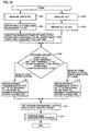
- CPU 27 performs communication with external device 25 or the like via connector 8 (S64).
- CPU 27 recognizes the usage mode as a result of the handshake operation (S64).
- CPU 27 determines that radio communication device 21 is used on a desk ("the mode of using the radio communication device on a desk” in S64), and the maximum transmission output value of "A” is obtained from usage mode vs. maximum transmission output storing unit 6 (S8). If the handshake operation fails or no handshake operation is performed, CPU 27 determines that the user uses radio communication device 21 while holding it to his/her ear ("the usage mode in which the user holds the radio communication device to his/her ear" in S64), and the maximum transmission output value of "C” is obtained from usage mode vs. maximum transmission output storing unit 6 (S12).
- control circuit 33 sets the maximum transmission output value obtained in the process of S8 or S12 into output control circuit 4 (S14). After that, the radio communication process is continued (S16).
- the embodiment by performing communication with an external device or the like, it becomes possible to output the optimum maximum output power from the antenna.
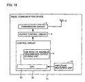
- a radio communication device 31 includes an antenna 5, an transmission circuit 2 connected to antenna 5, for transmitting an output signal from antenna 5, an output control circuit 4 connected to transmission circuit 2, for controlling an output of transmission circuit 2, a temperature measuring unit 11 for measuring either temperature in the periphery of radio communication device 31 or temperature of the surface of radio communication device 31, and a control circuit 33 connected to temperature measuring unit 11 and output control circuit 4, for controlling output control circuit 4 on the basis of an output result of temperature measuring unit 11.
- Control circuit 33 includes a usage mode vs. maximum transmission output storing unit 6 for storing a plurality of maximum transmission outputs which are predetermined in accordance with a plurality of usage modes of radio communication device 31, and a CPU 37 connected to usage mode vs. maximum transmission output storing unit 6 and temperature measuring unit 11, which executes processes according to a flow chart to be described hereinafter in accordance with the output result of temperature measuring unit 11 to thereby control output control circuit 4.
- the components of the radio communication device 31 operate as follows.
- usage modes there are two modes of a mode of using the radio communication device on a desk and a usage mode in which the user holds the radio communication device to his/her ear.
- the temperature of the surface of the radio communication device 31 is measured, and the distribution of the temperatures is checked. If the temperature distribution has a gentle change, it is determined that radio communication device 31 is used in a state where it is put on a desk. If the temperature distribution sharply changes in some positions, it is considered that radio communication device 31 is used by being held by his/her hand and held to his/her ear.
- Temperature measuring unit 11 measures the temperature of the surface of radio communication device 31 (S72), and reports the measured temperature to CPU 37 (S74).
- CPU 37 generates a distribution of temperatures of the surface of radio communication device 31 on the basis of the temperature measured by temperature measuring unit 11 (S76).
- CPU 37 determines whether the change in the distribution of the surface temperature of radio communication device 31 is gentle or sharp (S78). When the surface temperature distribution is gentle, CPU 37 determines that radio communication device 31 is used on a desk ("mode of using the radio communication device on a desk” in S78), and the maximum transmission output value of "A” is obtained from usage mode vs. maximum transmission output storing unit 6 (S8). When the surface temperature distribution is sharp, CPU 37 determines that the user uses radio communication device 31 by holding it to his/her ear ("mode in which the user uses the radio communication device by holding it to his/her ear” in S78), and the maximum transmission output value of "C” is obtained from usage mode vs. maximum transmission output storing unit 6 (S12).
- control circuit 33 sets the maximum transmission output value obtained by the process of S8 or S12 into output control circuit 4 (S14). After that, the radio communication process is continued (S16).
- the optimum maximum output power can be output from the antenna.
- a radio communication device 41 includes an antenna 5, a transmission circuit 2 connected to antenna 5, for transmitting an output signal from antenna 5, an output control circuit 4 connected to transmission circuit 2, for controlling an output of transmission circuit 2, a distance measuring unit 12 for measuring the distance from radio communication device 41 to an obstacle, and a control circuit 43 connected to distance measuring unit 12 and output control circuit 4, for controlling output control circuit 4 on the basis of an output result of distance measuring unit 12.
- Control circuit 43 includes a usage mode vs. maximum transmission output storing unit 6 for storing a plurality of maximum transmission outputs which are predetermined in accordance with a plurality of usage modes of radio communication device 41, and a CPU 47 connected to usage mode vs. maximum transmission output storing unit 6 and distance measuring unit 12, which executes processes according to a flow chart to be described hereinafter in accordance with the output result of distance measuring unit 12 to thereby control output control circuit 4.
- Distance measuring unit 12 reports the measured distance from radio communication device 41 to the obstacle to CPU 47, and CPU 47 recognizes the usage mode on the basis of the information from distance measuring unit 12.
- An example of a distance measuring method is a method of transmitting infrared, light, sound, or the like from radio communication device 41, measuring time taken for the infrared, light, sound, or the like reflected by the obstacle and returned to radio communication device 41, and obtaining the distance from the time.
- radio communication device 41 operate as follows.
- usage modes there are two modes of a mode of using the radio communication device on a desk and a usage mode in which the user holds the radio communication device to his/her ear.
- radio communication device 41 When the distance between radio communication device 41 and an obstacle (for example, the user) is equal to or longer than a predetermined threshold, it is considered that radio communication device 41 is used on a desk. When the distance is smaller than the threshold, it is considered that the user holds radio communication device 41 by his/her hand to his/her ear.
- the threshold is preset in CPU 47 and the correspondence relation between the distance from radio communication device 41 to an obstacle and the usage mode is stored in CPU 47. It is assumed that, in usage mode vs. maximum transmission output storing unit 6, the maximum output value of "A” is stored in the case of using the radio communication device on a desk, and the maximum output value of "C” is stored in the case of the usage mode in which the user holds the radio communication device to his/her ear.
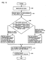
- Distance measuring unit 12 measures the distance from radio communication device 41 to the obstacle (S82), and reports the distance measurement result to CPU 47 (S84).
- CPU 47 determines whether or not the result of measuring the distance is equal to or longer than the predetermined threshold (S86). When the distance measurement result is equal to or longer than the threshold, CPU 47 determines that radio communication device 41 is used on a desk ("mode of using the radio communication device on a desk" in S86), and the maximum transmission output value of "A" is obtained from usage mode vs. maximum transmission output storing unit 6 (S8).
- CPU 47 determines that the user uses radio communication device 41 by holding it to his/her ear ("mode in which the user uses the radio communication device by holding it to his/her ear" in S86), and the maximum transmission output value of "C” is obtained from usage mode vs. maximum transmission output storing unit 6 (S12).
- control circuit 43 sets the maximum transmission output value obtained by the process of S8 or S12 into output control circuit 4 (S14). After that, the radio communication process is continued (S16).
- the distance between the radio communication device and an obstacle changes according to a usage mode
- the distance from the radio communication device to the obstacle for example, the user
- a radio communication device 51 includes an antenna 5, a transmission circuit 2 connected to antenna 5, for transmitting an output signal from antenna 5, an output control circuit 4 connected to transmission circuit 2, for controlling an output of transmission circuit 2, an amplitude measuring unit 13 for measuring an amplitude of oscillation of radio communication device 51, and a control circuit 53 connected to amplitude measuring unit 13 and output control circuit 4, for controlling output control circuit 4 on the basis of an output result of amplitude measuring unit 13.
- Control circuit 53 includes a usage mode vs. maximum transmission output storing unit 6 for storing a plurality of maximum transmission outputs which are predetermined in accordance with a plurality of usage modes of radio communication device 51, and a CPU 57 connected to usage mode vs. maximum transmission output storing unit 6 and amplitude measuring unit 13, which executes processes according to a flow chart to be described hereinafter in accordance with the output result of amplitude measuring unit 13 to thereby control output control circuit 4.
- radio communication device 51 operate as follows.
- usage modes there are two modes of a mode of using the radio communication device on a desk and a usage mode in which the user holds the radio communication device to his/her ear.
- the amplitude of radio communication device 51 is measured, and the number of times when radio communication device 51 oscillates with an amplitude equal to or larger than a predetermined amplitude threshold per unit time is counted. If the number of oscillation times of radio communication device 51 is smaller than the predetermined count threshold, it is considered that radio communication device 51 is used in a state where it is put on a desk. If the number of oscillation times is equal to or larger than the count threshold, it is considered that radio communication device 51 is used in a state where the user has radio communication device 51 by his/her hand and holds it to his/her ear.
- the unit time, amplitude threshold, and count threshold are preset in CPU 57, and the correspondence relation between the number of amplitude times and the usage mode is previously stored in CPU 57. It is assumed that, in usage mode vs. maximum transmission output storing unit 6, the maximum output value of "A” is stored in the case of using the radio communication device on a desk, and the maximum output value of "C” is stored in the case of the usage mode in which the user holds the radio communication device to his/her ear.
- Amplitude measuring unit 13 measures the amplitude of oscillation of radio communication device 51 (S92), and reports the amplitude measurement result to CPU 57 (S94).
- CPU 57 counts the number of times radio communication device 51 oscillates with an amplitude which is equal to or larger than the amplitude threshold per unit time (S96).
- CPU 57 determines whether the number of times is smaller than the count threshold value or not (S98). When the number of times is smaller than the count threshold, CPU 57 determines that radio communication device 51 is used on a desk ("mode of using the radio communication device on a desk" in S98), and the maximum transmission output value of "A" is obtained from usage mode vs. maximum transmission output storing unit 6 (S8).
- CPU 57 determines that the user uses radio communication device 51 by holding it to his/her ear ("mode in which the user uses the radio communication device by holding it to his/her ear” in S98), and the maximum transmission output value of "C” is obtained from usage mode vs. maximum transmission output storing unit 6 (S12).
- control circuit 53 sets the maximum transmission output value obtained by the process of S8 or S12 into output control circuit 4 (S14). After that, radio communication process is continued (S16).
- the optimum maximum output power can be output from the antenna.
- a radio communication device 61 includes an antenna 5, a transmission circuit 2 connected to antenna 5, for transmitting an output signal from antenna 5, an output control circuit 4 connected to transmission circuit 2, for controlling an output of transmission circuit 2, a tilt measuring unit 14 for measuring tilt of radio communication device 61, and a control circuit 63 connected to tilt measuring unit 14 and output control circuit 4, for controlling output control circuit 4 on the basis of an output result of tilt measuring unit 14.
- Control circuit 63 includes a usage mode vs. maximum transmission output storing unit 6 for storing a plurality of maximum transmission outputs which are predetermined in accordance with a plurality of usage modes of the radio communication device 61, and a CPU 67 connected to usage mode vs. maximum transmission output storing unit 6 and tilt measuring unit 14, which executes processes according to a flow chart to be described hereinafter in accordance with the output result of tilt measuring unit 14 to thereby control output control circuit 4.
- radio communication device 61 operate as follows.
- usage modes there are two modes of a mode of using the radio communication device on a desk and a usage mode in which the user holds the radio communication device to his/her ear.
- radio communication device 61 In the case of using radio communication device 61 on a desk, a dedicated holder for holding radio communication device 61 exists. Consequently, when the tilt of radio communication device 61 is larger than a predetermined first threshold and is smaller than a predetermined second threshold which is larger than the first threshold, it is considered that radio communication device 61 is held in the dedicated holder on a desk. In the other cases, it is considered that radio communication device 61 is used in a state that the user has radio communication device 61 by his/her hand and holds it to his/her ear.
- the first and second thresholds are preset in CPU 67, and the correspondence relation between the tilt of radio communication device 61 and the usage mode is previously stored in CPU 67. It is assumed that, in usage mode vs. maximum transmission output storing unit 6, the maximum output value of "A” is stored in the case of using the radio communication device on a desk, and the maximum output value of "C” is stored in the case of the usage mode in which the user holds the radio communication device to his/her ear.
- Tilt measuring unit 14 measures the tilt of radio communication device 61 (S102), and reports the tilt to CPU 67 (S104).
- CPU 67 determines whether or not the tilt of radio communication device 61 is larger than the first threshold value and smaller than the second threshold (S106). If the tilt of radio communication device 61 is larger than the first threshold and smaller than the second threshold value, CPU 67 determines that the radio communication device 61 is used on a desk ("mode of using the radio communication device on a desk" in S106), and the maximum transmission output value of "A" is obtained from usage mode vs. maximum transmission output storing unit 6 (S8).
- CPU 67 determines that the user uses radio communication device 61 by holding it to his/her ear ("mode in which the user uses the radio communication device by holding it to his/her ear" in S106), and the maximum transmission output value of "C” is obtained from usage mode vs. maximum transmission output storing unit 6 (S12).
- control circuit 63 sets the maximum transmission output value obtained by the process of S8 or S12 into output control circuit 4 (S14). After that, the radio communication process is continued (S16).
- the tilt of the radio communication device changes according to a usage mode
- the tilt of the radio communication device by measuring the tilt of the radio communication device, it becomes possible to output the optimum maximum output power from the antenna.
- a radio communication device 71 includes an antenna 5, a transmission circuit 2 connected to antenna 5, for transmitting an output signal from antenna 5, an output control circuit 4 connected to transmission circuit 2, for controlling an output of transmission circuit 2, an operation unit 15 for accepting an operation on radio communication device 71, and a control circuit 73 connected to operation unit 15 and output control circuit 4, for controlling output control circuit 4 on the basis of an output result of operation unit 15.
- Control circuit 73 includes a usage mode vs. maximum transmission output storing unit 6 for storing a plurality of maximum transmission outputs which are predetermined in accordance with a plurality of usage modes of radio communication device 71, and a CPU 77 connected to usage mode vs. maximum transmission output storing unit 6 and operation unit 15, which executes processes according to a flow chart to be described hereinafter in accordance with the output result of operation unit 15 to thereby control output control circuit 4.
- CPU 77 has a function of analyzing an operation performed on radio communication device 71 by the user. On the basis of a result of the analysis, the usage mode is recognized.
- radio communication device 71 operate as follows.
- usage modes there are two modes of a mode of using the radio communication device on a desk and a usage mode in which the user holds the radio communication device to his/her ear.
- radio communication device 71 In the case where the user "operates radio communication device 71 by using an AT command from an external device", it is considered that radio communication device 71 is used on a desk. In the other cases, it is considered that the user has radio communication device 71 on his/her hand and holds it to his/her ear.
- the AT command is a general command set used to control a modulator/demodulator (modem).
- modem modulator/demodulator
- CPU 77 receives an operation performed on radio communication device 71 by the user from operation unit 15 and analyzes it (S112).
- CPU 77 determines whether or not the user has performed an operation via operation unit 15 from an external device by using the AT command (S114).
- CPU 77 determines that radio communication device 71 is used on a desk ("mode of using the radio communication device on a desk" in S114), and the maximum transmission output value of "A" is obtained from usage mode vs. maximum transmission output storing unit 6 (S8).
- CPU 77 determines that the user uses radio communication device 71 by holding it to his/her ear ("mode in which the user uses the radio communication device by holding it to his/her ear" in S114), and the maximum transmission output value of "C” is obtained from usage mode vs. maximum transmission output storing unit 6 (S12).
- control circuit 73 sets the maximum transmission output value obtained by the process of S8 or S12 into output control circuit 4 (S14). After that, the radio communication process is continued (S16).
- the usage mode is determined by a specific operating method of the user, by analyzing the operation of the user, it becomes possible to output the optimum maximum output power from the antenna.
- a radio communication device 81 includes an antenna 5, a transmission circuit 2 connected to antenna 5, for transmitting an output signal from antenna 5, an output control circuit 4 connected to transmission circuit 2, for controlling an output of transmission circuit 2, an amplitude measuring unit 13 for measuring an amplitude of oscillation of radio communication device 81, a tilt measuring unit 14 for measuring tilt of radio communication device 81, and a control circuit 83 connected to amplitude measuring unit 13, tilt measuring unit 14, and output control circuit 4, for controlling output control circuit 4 on the basis of output results of amplitude measuring unit 13 and tilt measuring unit 14.
- Control circuit 83 includes a usage mode vs. maximum transmission output storing unit 6 for storing a plurality of maximum transmission outputs which are predetermined in accordance with a plurality of usage modes of radio communication device 81, and a CPU 87 connected to usage mode vs. maximum transmission output storing unit 6, amplitude measuring unit 13, and tilt measuring unit 14, which executes processes according to a flow chart to be described hereinafter in accordance with the output results of amplitude measuring unit 13 and tilt measuring unit 14 to thereby control output control circuit 4.
- radio communication device 81 operate as follows.
- usage modes there are two modes of a mode of using the radio communication device on a desk and a usage mode in which the user holds the radio communication device to his/her ear.
- radio communication device 81 In the case of using radio communication device 81 on a desk, a dedicated holder for holding radio communication device 81 exists. Consequently, when the tilt of radio communication device 81 is larger than a predetermined first threshold and is smaller than a predetermined second threshold which is larger than the first threshold, it is considered that radio communication device 81 is held in the dedicated holder on a desk. However, even when the tilt of radio communication device 81 lies between the first and second thresholds, a case where the user has radio communication device 81 by his/her hand and holds it to his/her ear can be also considered. Therefore, another condition is further added. The amplitude of radio communication device 81 is measured, and the number of times radio communication device 81 oscillates with an amplitude which is equal to or larger than the amplitude threshold per unit time is counted.
- radio communication device 81 only when the number of oscillation times of radio communication device 81 oscillates with the amplitude equal to or larger than the amplitude threshold is smaller than a count threshold and the tilt of radio communication device 81 lies between the first and second thresholds, it is considered that the radio communication device 81 is used on a desk. In the other cases, it is considered that radio communication device 81 is used in a state that the user holds it to his/her ear.
- the first and second thresholds, amplitude threshold, count threshold, and unit time are preset in CPU 87, and the correspondence relations between the tilt and number of oscillation times of radio communication device 81 and the usage mode are previously stored in CPU 87. It is assumed that, in usage mode vs. maximum transmission output storing unit 6, the maximum output value of "A” is stored in the case of the mode of using the radio communication device on a desk, and the maximum output value of "C” is stored in the case of the mode of using the radio communication device by holding it to user's ear.
- CPU 87 determines whether or not the number of oscillation times of radio communication device 81 is smaller than the count threshold and the tilt of radio communication device 81 is larger than the first threshold value and smaller than the second threshold (S122).
- CPU 87 determines that radio communication device 81 is used on a desk ("mode of using the radio communication device on a desk" in S122), and the maximum transmission output value of "A” is obtained from usage mode vs. maximum transmission output storing unit 6 (S8).
- CPU 87 determines that the user uses radio communication device 81 by holding it to his/her ear ("mode in which the user uses the radio communication device by holding it to his/her ear” in S122), and the maximum transmission output value of "C” is obtained from usage mode vs. maximum transmission output storing unit 6 (S 12).
- control circuit 83 sets the maximum transmission output value obtained by the process of S8 or S12 into output control circuit 4 (S14). After that, the radio communication process is continued (S16).
- the embodiment by preparing a plurality of realizing methods of recognizing the usage mode in accordance with the characteristics of the radio communication device, it becomes possible to output the optimum maximum output power from the antenna.
- the radio communication device As described above, in the radio communication device according to the invention, a usage mode of the user can be detected. Consequently, the invention is suitable for outputting an optimum maximum output power from an antenna in accordance with the usage mode of the user.
Landscapes
- Engineering & Computer Science (AREA)
- Computer Networks & Wireless Communication (AREA)
- Signal Processing (AREA)
- Human Computer Interaction (AREA)
- Transceivers (AREA)
- Transmitters (AREA)
- Telephone Function (AREA)
- Arrangements For Transmission Of Measured Signals (AREA)
Abstract
Description
- The present invention relates to a radio communication device and, more particularly, to a radio communication device capable of transmitting an optimum radio output in accordance with a usage mode.
- Conventionally, a booster (radio output amplifier) is generally connected to a portable telephone to enhance a radio output.
- For example, referring to Fig. 1, a radio communication device disclosed in Japanese Patent Laying-Open No. 8-65365 includes a
portable telephone 116 and abooster 117 connected to each other via an RF (Radio Frequency)signal line 118 and acontrol signal line 119. -
Portable telephone 116 includes anantenna 5, atransmission circuit 2 for transmitting an output signal, anoutput control circuit 4 for controlling an output oftransmission circuit 2, aswitch 120 connected totransmission circuit 2, for receiving the output signal of thetransmission circuit 2 as an input and leading the output signal tobooster 117 viaRF signal line 118 or toantenna 5 on the basis of a selection signal from a control circuit to be described hereinafter, and acontrol circuit 103 connected tooutput control circuit 4 and theswitch 120, for controllingoutput control circuit 4 and supplying the selection signal to switch 120. -
Control circuit 103 includes an amplificationlevel storing device 121, a maximum transmissionoutput storing device 122, aconnection detecting circuit 123, and a CPU (Central Processing Unit) 107. - Booster 117 includes an output amplifying
circuit 124 for amplifying an output signal received fromportable telephone 116 viaRF signal line 118, anoutput control circuit 125 connected to output amplifyingcircuit 124, for controlling an output from the output amplifying circuit, anantenna 127 connected to output amplifyingcircuit 124, and acontrol circuit 126 connected tocontrol signal line 119 andoutput control circuit 125, for controllingoutput control circuit 125. -
Control circuit 126 includes an amplificationlevel storing device 128 and aCPU 129 connected to amplificationlevel storing device 128. - When
booster 117 is connected toportable telephone 116, the connection ofbooster 117 is detected byconnection detecting circuit 123 inportable telephone 116. InCPU 107 inportable telephone 116, information indicating whetherportable telephone 116 is in a call mode or a standby mode is stored. According to the information,CPU 107 determines whetherportable telephone 116 is in the call mode or standby mode at the time whenbooster 117 is connected toportable telephone 116. - When it is determined that
booster 117 is connected during a call, onportable telephone 116 side, by an instruction ofCPU 107, information indicating thatportable telephone 116 andbooster 117 are connected is transmitted fromcontrol circuit 103 tobooster 117 viacontrol signal line 119.CPU 107 transmits information of a necessary amplification level onbooster 117 side, which is stored in amplificationlevel storing device 121 tobooster 117 viacontrol signal line 119. Further,CPU 107 calculates a transmission output value obtained by subtracting an output level stored in amplificationlevel storing device 121 from an output level stored in maximum transmissionoutput storing device 122 set at the start of a call. On the basis of the transmission output value,control circuit 103 transmits a control signal to outputcontrol circuit 4.Output control circuit 4 controlstransmission circuit 2 so as to set the transmission output to a desired level. - As a result, the output whose level has been changed is output from
transmission circuit 2. Simultaneously,control circuit 103 controls switch 120 to switch the direction of the radio signal fromantenna 5 of the portable telephone toRF signal line 118. The radio signal is supplied to output amplifyingcircuit 124 in booster viaRF signal line 118. - When
control circuit 126 inbooster 117 receives information thatportable telephone 116 andbooster 117 are connected to each other during a call fromportable telephone 116 viacontrol signal line 119,control circuit 126 notifiesCPU 129 of the information. Further, whencontrol circuit 126 receives the amplification level information fromportable telephone 116,control circuit 126 stores the information into amplificationlevel storing device 128. On the basis of the amplification level information stored in amplificationlevel storing device 128,CPU 129 controls output amplifyingcircuit 124 viaoutput control circuit 125. Output amplifyingcircuit 124 transmits the amplified output signal fromantenna 127. - In such a manner, a radio output control for controlling an output so as to not exceed a maximum transmission output which is set at the time of start of a call even when
portable telephone 116 is connected tobooster 117 during a call can be realized. That is, in the radio communication device, according to a mechanical difference whetherantenna 5 ofportable telephone 116 is used orantenna 127 ofbooster 117 is used, the maximum transmission output value of an output signal is adjusted. - In the device, however, when an output signal is desired to be changed to an optimum transmission output value according to a usage mode such as a mode of using the device on a desk or a mode of using the device by applying the portable telephone to an ear of the user, there is a problem that such a control cannot be performed.
- The present invention has been achieved to solve the problem and its object is to provide a radio communication device capable of changing an output signal to a proper transmission output value in accordance with a usage mode.
- Another object of the invention is to provide a radio communication device capable of automatically detecting the usage mode and changing an output signal to a proper transmission output value.
- A radio communication device according to an aspect of the invention includes: a storing unit for storing a plurality of maximum transmission outputs corresponding to a plurality of predetermined usage modes, a usage mode detecting unit for detecting a usage mode, a maximum transmission output determining unit connected to the usage mode detecting unit and the storing unit, for determining a maximum transmission output on the basis of a detection result of the usage mode detecting unit, a transmission circuit for transmitting a signal to the outside, and an output control circuit connected to the maximum transmission output determining unit and the transmission circuit, for controlling a transmission output from the transmission circuit on the basis of the maximum transmission output. A usage mode is detected by the usage mode detecting unit, and the maximum transmission output is determined on the basis of the usage mode. Consequently, according to the usage mode, the output signal can be changed to a proper transmission output value.
- Preferably, the usage mode detecting unit detects a usage mode at the time of receiving an incoming call or originating a call. Only at the time of receiving an incoming call or at the time of originating a call, the usage mode is detected. Consequently, in the case where the usage mode is not changed during communication, the number of processes of the usage mode detecting unit can be minimized.
- More preferably, the usage mode detecting unit detects the usage mode at turn-on of the radio communication device. The usage mode is detected only at turn-on. Consequently, in the case of a radio communication device in which the usage mode is not changed after turn-on, the number of processes of the usage mode detecting unit can be minimized.
- More preferably, the usage mode detecting unit includes a temperature measuring unit for measuring temperature of the periphery of the radio communication device, and a detecting circuit connected to the temperature measuring unit, for detecting a usage mode on the basis of an output result of the temperature measuring unit. When the temperature of the periphery of the radio communication device changes according to the usage mode, by measuring the temperature of the periphery of the radio communication device, the usage mode is detected, and the output signal can be changed to a proper transmission output value.
- More preferably, the usage mode detecting unit includes a distance measuring unit for measuring a distance from the radio communication device to an obstacle, and a detecting circuit connected to the distance measuring unit, for detecting the usage mode on the basis of an output result of the distance measuring unit. When the distance between the radio communication device and an obstacle (for example, the user) changes according to the usage mode, by measuring the distance from the radio communication device to the obstacle (for example, the user), the usage mode is detected, and an output signal can be changed to a proper transmission output value.
- More preferably, the usage mode detecting unit includes an amplitude measuring unit for measuring amplitude of oscillation of the radio communication device, and a detecting circuit connected to the amplitude measuring unit, for detecting a usage mode on the basis of an output result of the amplitude measuring unit. When the oscillation of the radio communication device changes according to the usage mode, by measuring the amplitude of oscillation of the radio communication device, the usage mode is detected, and an output signal can be changed to a proper transmission output value.
- More preferably, the usage mode detecting unit includes a tilt measuring unit for measuring a tilt of the radio communication device, and a detecting circuit connected to the tilt measuring unit, for detecting a usage mode on the basis of an output result of the tilt measuring unit. When the tilt of the radio communication device changes according to the usage mode, by measuring the tilt of the radio communication device, the usage mode is detected, and an output signal can be changed to a proper transmission output value.
- More preferably, the usage mode detecting unit includes an operation unit for receiving an operation on the radio communication device, and a detecting circuit connected to the operation unit, for detecting a usage mode on the basis of an output result of the operation unit. When the usage mode is determined by an operating method particular to the user, by analyzing the operation of the user, the usage mode is detected, and an output signal can be changed to a proper transmission output value.
- More preferably, the usage mode detecting unit includes an amplitude measuring unit for measuring amplitude of oscillation of the radio communication device, a tilt measuring unit for measuring a tilt of the radio communication unit, and a detecting circuit connected to the amplitude measuring unit and the tilt measuring unit, for detecting a usage mode on the basis of output results of the amplitude measuring unit and the tilt measuring unit.
- By preparing a plurality of realizing methods of recognizing the usage mode in accordance with the characteristics of the radio communication device, the usage mode is detected, and an output signal can be changed to a proper transmission output value.
-
- Fig. 1 is a block diagram showing a hardware configuration of a radio communication device disclosed in Japanese Patent Laying-Open No. 8-65365.
- Fig. 2 is a block diagram showing a hardware configuration of a radio communication device according to a first embodiment of the present invention.
- Fig. 3 is a flow chart of processes executed by the radio communication device according to the first embodiment.
- Fig. 4 is a diagram for explaining a mode of using the radio communication device on a desk.
- Fig. 5 is a diagram for explaining a mode of using the radio communication device in a bag.
- Fig. 6 is a diagram for explaining a mode of using the radio communication device which is applied to an ear of the user.
- Fig. 7 is a flow chart of processes executed by a radio communication device according to a second embodiment.
- Fig. 8 is a flow chart of a usage mode recognizing process of S28 and S38 in Fig. 7.
- Fig. 9 is a flow chart of processes executed by a radio communication device according to a third embodiment.
- Fig. 10 is a block diagram showing the hardware configuration of a radio communication device according to a fourth embodiment.
- Fig. 11 is a flowchart showing processes executed by the radio communication device according to the fourth embodiment.
- Fig. 12 is a block diagram showing the hardware configuration of a radio communication device according to a fifth embodiment.
- Fig. 13 is a flow chart showing processes executed by the radio communication device according to the fifth embodiment.
- Fig. 14 is a block diagram showing the hardware configuration of a radio communication device according to a sixth embodiment.
- Fig. 15 is a flow chart showing processes executed by the radio communication device according to the sixth embodiment.
- Fig. 16 is a block diagram showing the hardware configuration of a radio communication device according to a seventh embodiment.
- Fig. 17 is a flow chart of processes.executed by the radio communication device according to the seventh embodiment.
- Fig. 18 is a block diagram showing the hardware configuration of a radio communication device according to an eighth embodiment.
- Fig. 19 is a flow chart of processes executed by the radio communication device according to the eighth embodiment.
- Fig. 20 is a block diagram showing the hardware configuration of a radio communication device according to a ninth embodiment.
- Fig. 21 is a flow chart of processes executed by the radio communication device according to the ninth embodiment.
- Fig. 22 is a block diagram showing the hardware configuration of a radio communication device according to a tenth embodiment.
- Fig. 23 is a flow chart of processes executed by the radio communication device according to the tenth embodiment.
-
- Referring to Fig. 2, a
radio communication device 1 according to a first embodiment of the present invention includes anantenna 5, atransmission circuit 2 connected toantenna 5, for transmitting an output signal fromantenna 5, anoutput control circuit 4 connected totransmission circuit 2, for controlling an output oftransmission circuit 2, twoconnectors unit 10 for detecting connection of an external device or the like, which detects whether or not an external device or the like is connected toconnector control circuit 3 connected toconnectors unit 10 for detecting connection of an external device, andoutput control circuit 4, for controllingoutput control circuit 4 in accordance with an output ofunit 10 for detecting connection of an external device. -
Control circuit 3 includes a usage mode vs. maximum transmissionoutput storing unit 6 for storing a plurality of maximum transmission outputs determined according to a plurality of usage modes ofradio communication device 1, and aCPU 7 connected to usage mode vs. maximum transmissionoutput storing unit 6 andunit 10 for detecting connection of an external device, for controllingoutput control circuit 4 by executing processes of a flow chart which will be described hereinafter in accordance with an output ofunit 10 for detecting connection of an external device. - Referring to Fig. 3, the components of
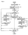
radio communication device 1 operate as follows. It is assumed here that there are total three usage modes of theradio communication device 1; a mode of usingradio communication device 1 on a desk as shown in Fig. 4, a mode of usingradio communication device 1 in a bag as shown in Fig. 5, and a mode of usingradio communication device 1 by being applied to an ear of the user as shown in Fig. 6. - In
radio communication device 1, twoconnectors connector 8, it is determined thatradio communication device 1 is used on a desk. In the case where the external device or the like is connected toconnector 9, it is determined thatradio communication device 1 is used in a bag. In the case where no external device is connected to any ofconnectors ratio communication device 1 by applying it to his/her ear. The correspondence relations between the connection of an external device or the like and the usage modes are stored inCPU 7. It is assumed that, for example, in usage mode vs. maximum transmissionoutput storing unit 6, a maximum transmission output value "A" is stored in the case of the mode of usingradio communication device 1 on a desk, a maximum transmission output value "B" is stored in the case of the mode of usingradio communication device 1 in a bag, and a maximum transmission output value "C" is stored in the case of the mode of usingradio communication device 1 by being applied to an ear of the user. -
Unit 10 for detecting connection of an external device or the like detects a connection state of an external device or the like toconnector 8 or 9 (S2).Unit 10 for detecting connection of an external device or the like reports a detection result to CPU 7 (S3). For example, when connection of an external device or the like toconnector 8 is detected,unit 10 for detecting connection of an external device or the like reports that "there is connection of an external device or the like toconnector 8" toCPU 7. -
CPU 7 determines the usage mode in accordance with the report fromunit 10 for detecting connection of an external device or the like (S6). For example, when it is reported that "there is connection of an external device or the like toconnector 8",CPU 7 determines the mode of usingradio communication device 1 on a desk. The relations between the connection states ofconnectors - When the mode of using
radio communication device 1 on a desk is determined ("mode of usingradio communication device 1 on a desk" in S6),CPU 7 obtains the maximum transmission output value of "A" from usage mode vs. maximum transmission output storing unit 6 (S8). - When the mode of using
radio communication device 1 in a bag is determined ("mode of usingradio communication device 1 in a bag" in S6),CPU 7 obtains the maximum transmission output value of "B" from usage mode vs. maximum transmission output storing unit 6 (S10). - When the mode of using
radio communication device 1 by being applied to an ear of the user is determined ("mode of using theradio communication device 1 by being applied to an ear of the user" in S6),CPU 7 obtains the maximum transmission output value of "C" from user mode maximum transmission output correspondence storing unit 6 (S12). - According to the instruction of
CPU 7,control circuit 3 sets the maximum transmission output value obtained by the process in any of S8 to S12 into output control circuit 4 (S14). After that, the radio communication process is continued (S16). - The above-described process is always performed in the background or by an interrupting process using a timer separately from the communication of the radio communication device.
- According to the embodiment, even when the usage mode is changed by connection of an external device or the like, it can be controlled so that the maximum output power from the antenna becomes the optimum value.
- According to the usage mode such as a case of using the radio communication device on a desk, the case of using the radio communication device in a bag, or the case of using the radio communication device by being applied to an ear of the user, the maximum output power from the antenna can be controlled to be the optimum power.
- Further, the processes shown in Fig. 3 are always performed in the background or by an interrupting process using a timer separately from the communication of the radio communication device. Consequently, the optimum maximum output power can be output from the antenna always in response to a change in the usage mode.
- A radio communication device according to a second embodiment of the present invention has a hardware configuration similar to that of the radio communication device described by referring to Fig. 2. Consequently, the detailed description will not be repeated here.
- In the first embodiment, the process of recognizing the usage mode is always performed in the background or by the timer interrupting process. In the second embodiment, the process of recognizing the usage mode is performed before a response to an incoming call or before transmission of a call originating request.
- Referring to Fig. 7, components of a
radio communication device 1 operate as follows. - When the power of
radio communication device 1 is turned on (S22),radio communication device 1 shifts to a standby mode (S4). Acontrol circuit 3 determines whetherradio communication device 1 has received an incoming call or not (S26). When theradio communication device 1 has received an incoming call (YES in S26), in aCPU 7, the usage mode recognizing process for recognizing the usage mode ofradio communication device 1 is executed (S28). The usage mode recognizing process will be described hereinafter. - After S28,
radio communication device 1 responds to the incoming call (S30) and continues the radio communicating process (S32).Control circuit 3 determines whether the communication has finished or not (S34). If the communication is not finished (NO in S34), the routine returns to S32. If the communication has been finished (YES in S34), the routine returns to S24 and the standby mode is set again. - If
radio communication device 1 has not received an incoming call (NO in S26),control circuit 3 determines whether a call originating operation is performed by the user or not (S36). When it is determined that the call originating operation is performed (YES in S36), a usage mode recognizing process similar to S28 is executed (S38). After S38, a call originating request is transmitted from a transmission circuit 2 (S40). After that, the radio communication process is continued (S42).Control circuit 3 determines whether communication has been finished or not (S44). If the communication has not been finished (NO in S44), the routine returns to S42. If the communication has been finished (YES in S44), the routine returns to S24, and the standby mode is set again. - If there is no incoming call nor call originating operation (NO in S26 and NO in S36),
control circuit 3 determines whether the power source ofradio communication device 1 has been turned off or not (NO in S46). If the power source ofradio communication device 1 has not been turned off (NO in S46), the routine returns to S24 and the standby mode is set again. If the power source ofradio communication device 1 is turned off (YES in S46), the process is finished. - Referring to Fig. 8, the usage mode recognizing process in S28 and S38 in Fig. 7 will be described. The process is a process of recognizing the usage mode of
radio communication device 1 and setting the proper maximum transmission output value into anoutput control circuit 4. The details of the process are similar to those of the processes of S6 to S14 in Fig. 3. Consequently, the detailed description will not be repeated here. - According to the embodiment, the usage mode recognizing process is performed only before response to an incoming call or before transmission of a call originating request. Consequently, in the case of a radio communication device whose usage mode is not changed during communication, the number of times of performing the usage mode recognizing process can be reduced as compared with the first embodiment. As a result, the power consumption of the radio communication device can be reduced.
- A radio communication device according to a third embodiment. of the present invention has a hardware configuration similar to that of the radio communication device described by referring to Fig. 2. Consequently, the detailed description will not be repeated here.
- In the first embodiment, the process of recognizing the usage mode is always performed in the background or by a timer interrupting process. In the third embodiment, the process of recognizing the usage mode is performed at turn-on of the power source.
- Referring to Fig. 9, components of a
radio communication device 1 operate as follows. - When the power source of
radio communication device 1 is turned on (S22), a usage mode recognizing process (S52) is performed. The usage mode recognizing process is similar to that described by referring to Fig. 8, so that its description will not be repeated here. - After the usage mode recognizing process (S52),
radio communication device 1 shifts to a standby mode (S24). The processes after the shift to the standby mode are similar to those in Fig. 7 except for the usage mode recognizing process in S28 and S38. Consequently, the detailed description will not be repeated here. - According to the third embodiment, the usage mode recognizing process is performed only when the power source of
radio communication device 1 is turned on. Consequently, in the case of the radio communication device whose usage mode is not changed after the turn-on of the power, the number of times of performing the usage mode recognizing process can be reduced as compared with the first and second embodiments. As a result, the power consumption of the radio communication device can be reduced. - With reference to Fig. 10, a
radio communication device 21 according to a fourth embodiment of the present invention includes anantenna 5, atransmission circuit 2 connected toantenna 5, for transmitting an output signal fromantenna 5, anoutput control circuit 4 connected totransmission circuit 2, for controlling an output oftransmission circuit 2, aconnector 8, and acontrol circuit 23 connected toconnector 8 andoutput control circuit 4, for controllingoutput control circuit 4 on the basis of the connection state of anexternal device 25 or the like toconnector 8. -
Control circuit 23 includes a usage mode vs. maximum transmissionoutput storing unit 6 for storing a plurality of maximum transmission outputs which are predetermined in accordance with a plurality of usage modes ofradio communication device 21, and aCPU 27 connected to usage mode vs. maximum transmissionoutput storing unit 6 andconnector 8, which executes processes according to a flow chart to be described hereinafter in accordance with the connection state ofexternal device 25 or the like toconnector 8 to thereby controloutput control circuit 4. -
CPU 27 performs communications with an external device or the like connected to the connector and, on the basis of the information, recognizes the usage mode of aradio communication device 21. - Referring to Fig. 11, the components of
radio communication device 21 operate as follows. - It is now assumed that, as usage modes, there are two modes of a mode of using the radio communication device on a desk and a mode of using the radio communication device by being applied to an ear of the user.
- For example, when a camera unit is connected as an external device to
connector 8 andradio communication device 21 is used as a TV telephone by using the camera unit, an image of the user himself/herself has to be captured by the camera. In such a case, the mode of using the radio communication device on a desk can be considered. - On the other hand, when the mode of using the radio communication device on a desk cannot be determined only from connection of the camera unit to
connector 8, for example, in the case where the radio communication device to which the camera unit is attached is not used as a TV telephone but only voice is transmitted/received, the mode of using the radio communication device by being applied to an ear of the user is determined. - When
radio communication device 21 and the camera unit are used as a TV telephone, it is necessary to capture image data from the camera unit. At the time of capturing image data, a data passing process (hereinafter, referred to as "handshake operation") for checking whether connection of data betweenradio communication device 21 and the camera unit is successful or not is performed. In the case where the handshake operation is performed betweenradio communication device 21 and the camera unit, the mode of usingradio communication device 21 on a desk is determined. In the other cases, it is considered that the user usesradio communication device 21 by holding it by a hand and applying it to his/her ear. - It is assumed that the correspondence relation between the result of communication with
external device 25 or the like and the usage mode is previously stored inCPU 27. In usage mode vs. maximum transmissionoutput storing unit 6, a maximum output value of "A" is stored in the case of the mode of using the radio communication device on a desk and a maximum output value of "C" is stored in the case of the usage mode in which the user holds the radio communication device to his/her ear. -
CPU 27 performs communication withexternal device 25 or the like via connector 8 (S64). -
CPU 27 recognizes the usage mode as a result of the handshake operation (S64). WhenCPU 27 succeeds in the handshake operation,CPU 27 determines thatradio communication device 21 is used on a desk ("the mode of using the radio communication device on a desk" in S64), and the maximum transmission output value of "A" is obtained from usage mode vs. maximum transmission output storing unit 6 (S8). If the handshake operation fails or no handshake operation is performed,CPU 27 determines that the user usesradio communication device 21 while holding it to his/her ear ("the usage mode in which the user holds the radio communication device to his/her ear" in S64), and the maximum transmission output value of "C" is obtained from usage mode vs. maximum transmission output storing unit 6 (S12). - According to an instruction of a
CPU 37,control circuit 33 sets the maximum transmission output value obtained in the process of S8 or S12 into output control circuit 4 (S14). After that, the radio communication process is continued (S16). - According to the embodiment, by performing communication with an external device or the like, it becomes possible to output the optimum maximum output power from the antenna.
- Referring to Fig. 12, a
radio communication device 31 according to a fifth embodiment of the present invention includes anantenna 5, antransmission circuit 2 connected toantenna 5, for transmitting an output signal fromantenna 5, anoutput control circuit 4 connected totransmission circuit 2, for controlling an output oftransmission circuit 2, atemperature measuring unit 11 for measuring either temperature in the periphery ofradio communication device 31 or temperature of the surface ofradio communication device 31, and acontrol circuit 33 connected totemperature measuring unit 11 andoutput control circuit 4, for controllingoutput control circuit 4 on the basis of an output result oftemperature measuring unit 11. -
Control circuit 33 includes a usage mode vs. maximum transmissionoutput storing unit 6 for storing a plurality of maximum transmission outputs which are predetermined in accordance with a plurality of usage modes ofradio communication device 31, and aCPU 37 connected to usage mode vs. maximum transmissionoutput storing unit 6 andtemperature measuring unit 11, which executes processes according to a flow chart to be described hereinafter in accordance with the output result oftemperature measuring unit 11 to thereby controloutput control circuit 4. - Referring to Fig. 13, the components of the
radio communication device 31 operate as follows. - It is now assumed that, as usage modes, there are two modes of a mode of using the radio communication device on a desk and a usage mode in which the user holds the radio communication device to his/her ear.
- The temperature of the surface of the
radio communication device 31 is measured, and the distribution of the temperatures is checked. If the temperature distribution has a gentle change, it is determined thatradio communication device 31 is used in a state where it is put on a desk. If the temperature distribution sharply changes in some positions, it is considered thatradio communication device 31 is used by being held by his/her hand and held to his/her ear. - It is assumed that the reference used to determine the degree of a change in the temperature distribution is preset in
CPU 37, and the correspondence relation between the distribution of the temperatures of the surface ofradio communication device 31 and the usage mode is stored inCPU 37. It is assumed that, in usage mode vs. maximum transmissionoutput storing unit 6, a maximum output value of "A" is stored in the case of using the radio communication device on a desk, and a maximum output value of "C" is stored in the case of the usage mode in which the user holds the radio communication device to his/her ear. -
Temperature measuring unit 11 measures the temperature of the surface of radio communication device 31 (S72), and reports the measured temperature to CPU 37 (S74).CPU 37 generates a distribution of temperatures of the surface ofradio communication device 31 on the basis of the temperature measured by temperature measuring unit 11 (S76). -
CPU 37 determines whether the change in the distribution of the surface temperature ofradio communication device 31 is gentle or sharp (S78). When the surface temperature distribution is gentle,CPU 37 determines thatradio communication device 31 is used on a desk ("mode of using the radio communication device on a desk" in S78), and the maximum transmission output value of "A" is obtained from usage mode vs. maximum transmission output storing unit 6 (S8). When the surface temperature distribution is sharp,CPU 37 determines that the user usesradio communication device 31 by holding it to his/her ear ("mode in which the user uses the radio communication device by holding it to his/her ear" in S78), and the maximum transmission output value of "C" is obtained from usage mode vs. maximum transmission output storing unit 6 (S12). - According to the instruction of
CPU 37,control circuit 33 sets the maximum transmission output value obtained by the process of S8 or S12 into output control circuit 4 (S14). After that, the radio communication process is continued (S16). - According to the embodiment, in the case where the temperature of the periphery or the temperature of the surface of the radio communication device changes according to a usage mode, the optimum maximum output power can be output from the antenna.
- Referring to Fig. 14, a
radio communication device 41 according to a sixth embodiment of the present invention includes anantenna 5, atransmission circuit 2 connected toantenna 5, for transmitting an output signal fromantenna 5, anoutput control circuit 4 connected totransmission circuit 2, for controlling an output oftransmission circuit 2, adistance measuring unit 12 for measuring the distance fromradio communication device 41 to an obstacle, and acontrol circuit 43 connected to distance measuringunit 12 andoutput control circuit 4, for controllingoutput control circuit 4 on the basis of an output result ofdistance measuring unit 12. -
Control circuit 43 includes a usage mode vs. maximum transmissionoutput storing unit 6 for storing a plurality of maximum transmission outputs which are predetermined in accordance with a plurality of usage modes ofradio communication device 41, and aCPU 47 connected to usage mode vs. maximum transmissionoutput storing unit 6 anddistance measuring unit 12, which executes processes according to a flow chart to be described hereinafter in accordance with the output result ofdistance measuring unit 12 to thereby controloutput control circuit 4. - Distance measuring
unit 12 reports the measured distance fromradio communication device 41 to the obstacle toCPU 47, andCPU 47 recognizes the usage mode on the basis of the information fromdistance measuring unit 12. An example of a distance measuring method is a method of transmitting infrared, light, sound, or the like fromradio communication device 41, measuring time taken for the infrared, light, sound, or the like reflected by the obstacle and returned toradio communication device 41, and obtaining the distance from the time. - Referring to Fig. 15, the components of
radio communication device 41 operate as follows. - It is now assumed that, as usage modes, there are two modes of a mode of using the radio communication device on a desk and a usage mode in which the user holds the radio communication device to his/her ear.
- When the distance between
radio communication device 41 and an obstacle (for example, the user) is equal to or longer than a predetermined threshold, it is considered thatradio communication device 41 is used on a desk. When the distance is smaller than the threshold, it is considered that the user holdsradio communication device 41 by his/her hand to his/her ear. - It is assumed that the threshold is preset in
CPU 47 and the correspondence relation between the distance fromradio communication device 41 to an obstacle and the usage mode is stored inCPU 47. It is assumed that, in usage mode vs. maximum transmissionoutput storing unit 6, the maximum output value of "A" is stored in the case of using the radio communication device on a desk, and the maximum output value of "C" is stored in the case of the usage mode in which the user holds the radio communication device to his/her ear. - Distance measuring
unit 12 measures the distance fromradio communication device 41 to the obstacle (S82), and reports the distance measurement result to CPU 47 (S84).CPU 47 determines whether or not the result of measuring the distance is equal to or longer than the predetermined threshold (S86). When the distance measurement result is equal to or longer than the threshold,CPU 47 determines thatradio communication device 41 is used on a desk ("mode of using the radio communication device on a desk" in S86), and the maximum transmission output value of "A" is obtained from usage mode vs. maximum transmission output storing unit 6 (S8). When the distance measurement result is less than the threshold,CPU 47 determines that the user usesradio communication device 41 by holding it to his/her ear ("mode in which the user uses the radio communication device by holding it to his/her ear" in S86), and the maximum transmission output value of "C" is obtained from usage mode vs. maximum transmission output storing unit 6 (S12). - According to the instruction of
CPU 47,control circuit 43 sets the maximum transmission output value obtained by the process of S8 or S12 into output control circuit 4 (S14). After that, the radio communication process is continued (S16). - According to the embodiment, in the case where the distance between the radio communication device and an obstacle (for example, the user) changes according to a usage mode, by measuring the distance from the radio communication device to the obstacle (for example, the user), it becomes possible to output the optimum maximum output power from the antenna.
- With reference to Fig. 16, a
radio communication device 51 according to a seventh embodiment of the present invention includes anantenna 5, atransmission circuit 2 connected toantenna 5, for transmitting an output signal fromantenna 5, anoutput control circuit 4 connected totransmission circuit 2, for controlling an output oftransmission circuit 2, anamplitude measuring unit 13 for measuring an amplitude of oscillation ofradio communication device 51, and acontrol circuit 53 connected to amplitude measuringunit 13 andoutput control circuit 4, for controllingoutput control circuit 4 on the basis of an output result ofamplitude measuring unit 13. -
Control circuit 53 includes a usage mode vs. maximum transmissionoutput storing unit 6 for storing a plurality of maximum transmission outputs which are predetermined in accordance with a plurality of usage modes ofradio communication device 51, and aCPU 57 connected to usage mode vs. maximum transmissionoutput storing unit 6 andamplitude measuring unit 13, which executes processes according to a flow chart to be described hereinafter in accordance with the output result ofamplitude measuring unit 13 to thereby controloutput control circuit 4. - Referring to Fig. 17, the components of
radio communication device 51 operate as follows. - It is now assumed that, as usage modes, there are two modes of a mode of using the radio communication device on a desk and a usage mode in which the user holds the radio communication device to his/her ear.
- The amplitude of
radio communication device 51 is measured, and the number of times whenradio communication device 51 oscillates with an amplitude equal to or larger than a predetermined amplitude threshold per unit time is counted. If the number of oscillation times ofradio communication device 51 is smaller than the predetermined count threshold, it is considered thatradio communication device 51 is used in a state where it is put on a desk. If the number of oscillation times is equal to or larger than the count threshold, it is considered thatradio communication device 51 is used in a state where the user hasradio communication device 51 by his/her hand and holds it to his/her ear. - It is assumed that the unit time, amplitude threshold, and count threshold are preset in
CPU 57, and the correspondence relation between the number of amplitude times and the usage mode is previously stored inCPU 57. It is assumed that, in usage mode vs. maximum transmissionoutput storing unit 6, the maximum output value of "A" is stored in the case of using the radio communication device on a desk, and the maximum output value of "C" is stored in the case of the usage mode in which the user holds the radio communication device to his/her ear. -
Amplitude measuring unit 13 measures the amplitude of oscillation of radio communication device 51 (S92), and reports the amplitude measurement result to CPU 57 (S94).CPU 57 counts the number of timesradio communication device 51 oscillates with an amplitude which is equal to or larger than the amplitude threshold per unit time (S96).CPU 57 determines whether the number of times is smaller than the count threshold value or not (S98). When the number of times is smaller than the count threshold,CPU 57 determines thatradio communication device 51 is used on a desk ("mode of using the radio communication device on a desk" in S98), and the maximum transmission output value of "A" is obtained from usage mode vs. maximum transmission output storing unit 6 (S8). When the number of times is equal to or larger than the count threshold,CPU 57 determines that the user usesradio communication device 51 by holding it to his/her ear ("mode in which the user uses the radio communication device by holding it to his/her ear" in S98), and the maximum transmission output value of "C" is obtained from usage mode vs. maximum transmission output storing unit 6 (S12). - According to the instruction of
CPU 57,control circuit 53 sets the maximum transmission output value obtained by the process of S8 or S12 into output control circuit 4 (S14). After that, radio communication process is continued (S16). - According to the embodiment, in the case where the oscillation of the radio communication device changes according to a usage mode, by measuring the-amplitude of the oscillation of the radio communication device, the optimum maximum output power can be output from the antenna.
- Referring to Fig. 18, a
radio communication device 61 according to an eighth embodiment of the present invention includes anantenna 5, atransmission circuit 2 connected toantenna 5, for transmitting an output signal fromantenna 5, anoutput control circuit 4 connected totransmission circuit 2, for controlling an output oftransmission circuit 2, atilt measuring unit 14 for measuring tilt ofradio communication device 61, and acontrol circuit 63 connected to tilt measuringunit 14 andoutput control circuit 4, for controllingoutput control circuit 4 on the basis of an output result oftilt measuring unit 14. -
Control circuit 63 includes a usage mode vs. maximum transmissionoutput storing unit 6 for storing a plurality of maximum transmission outputs which are predetermined in accordance with a plurality of usage modes of theradio communication device 61, and aCPU 67 connected to usage mode vs. maximum transmissionoutput storing unit 6 andtilt measuring unit 14, which executes processes according to a flow chart to be described hereinafter in accordance with the output result oftilt measuring unit 14 to thereby controloutput control circuit 4. - Referring to Fig. 19, the components of
radio communication device 61 operate as follows. - It is now assumed that, as usage modes, there are two modes of a mode of using the radio communication device on a desk and a usage mode in which the user holds the radio communication device to his/her ear.
- In the case of using
radio communication device 61 on a desk, a dedicated holder for holdingradio communication device 61 exists. Consequently, when the tilt ofradio communication device 61 is larger than a predetermined first threshold and is smaller than a predetermined second threshold which is larger than the first threshold, it is considered thatradio communication device 61 is held in the dedicated holder on a desk. In the other cases, it is considered thatradio communication device 61 is used in a state that the user hasradio communication device 61 by his/her hand and holds it to his/her ear. - It is assumed that the first and second thresholds are preset in
CPU 67, and the correspondence relation between the tilt ofradio communication device 61 and the usage mode is previously stored inCPU 67. It is assumed that, in usage mode vs. maximum transmissionoutput storing unit 6, the maximum output value of "A" is stored in the case of using the radio communication device on a desk, and the maximum output value of "C" is stored in the case of the usage mode in which the user holds the radio communication device to his/her ear. - Tilt measuring
unit 14 measures the tilt of radio communication device 61 (S102), and reports the tilt to CPU 67 (S104). -
CPU 67 determines whether or not the tilt ofradio communication device 61 is larger than the first threshold value and smaller than the second threshold (S106). If the tilt ofradio communication device 61 is larger than the first threshold and smaller than the second threshold value,CPU 67 determines that theradio communication device 61 is used on a desk ("mode of using the radio communication device on a desk" in S106), and the maximum transmission output value of "A" is obtained from usage mode vs. maximum transmission output storing unit 6 (S8). When the tilt ofradio communication device 61 is other than the above,CPU 67 determines that the user usesradio communication device 61 by holding it to his/her ear ("mode in which the user uses the radio communication device by holding it to his/her ear" in S106), and the maximum transmission output value of "C" is obtained from usage mode vs. maximum transmission output storing unit 6 (S12). - According to the instruction of
CPU 67,control circuit 63 sets the maximum transmission output value obtained by the process of S8 or S12 into output control circuit 4 (S14). After that, the radio communication process is continued (S16). - According to the embodiment, in the case where the tilt of the radio communication device changes according to a usage mode, by measuring the tilt of the radio communication device, it becomes possible to output the optimum maximum output power from the antenna.
- Referring to Fig. 20, a
radio communication device 71 according to a ninth embodiment of the present invention includes anantenna 5, atransmission circuit 2 connected toantenna 5, for transmitting an output signal fromantenna 5, anoutput control circuit 4 connected totransmission circuit 2, for controlling an output oftransmission circuit 2, anoperation unit 15 for accepting an operation onradio communication device 71, and acontrol circuit 73 connected tooperation unit 15 andoutput control circuit 4, for controllingoutput control circuit 4 on the basis of an output result ofoperation unit 15. -
Control circuit 73 includes a usage mode vs. maximum transmissionoutput storing unit 6 for storing a plurality of maximum transmission outputs which are predetermined in accordance with a plurality of usage modes ofradio communication device 71, and aCPU 77 connected to usage mode vs. maximum transmissionoutput storing unit 6 andoperation unit 15, which executes processes according to a flow chart to be described hereinafter in accordance with the output result ofoperation unit 15 to thereby controloutput control circuit 4. -
CPU 77 has a function of analyzing an operation performed onradio communication device 71 by the user. On the basis of a result of the analysis, the usage mode is recognized. - Referring to Fig. 21, the components of
radio communication device 71 operate as follows. - It is now assumed that, as usage modes, there are two modes of a mode of using the radio communication device on a desk and a usage mode in which the user holds the radio communication device to his/her ear.
- In the case where the user "operates
radio communication device 71 by using an AT command from an external device", it is considered thatradio communication device 71 is used on a desk. In the other cases, it is considered that the user hasradio communication device 71 on his/her hand and holds it to his/her ear. The AT command is a general command set used to control a modulator/demodulator (modem). As a case of using the AT command, a case of usingradio communication device 71 as a modem, connecting a personal computer or the like toradio communication device 71, and performing data transfer or the like can be considered. - It is assumed that operations of the user to be analyzed are preset in
CPU 77, and the correspondence relation between the operation onradio communication device 71 by the user and the usage mode is previously stored in the CPU. It is assumed that, in the usage mode vs. maximum transmissionoutput storing unit 6, the maximum output value of "A" is stored in the case of using the radio communication device on a desk, and the maximum output value of "C" is stored in the case of the usage mode in which the user holds the radio communication device to his/her ear. -
CPU 77 receives an operation performed onradio communication device 71 by the user fromoperation unit 15 and analyzes it (S112).CPU 77 determines whether or not the user has performed an operation viaoperation unit 15 from an external device by using the AT command (S114). When the user operatesradio communication device 71 from an external device by using the AT command,CPU 77 determines thatradio communication device 71 is used on a desk ("mode of using the radio communication device on a desk" in S114), and the maximum transmission output value of "A" is obtained from usage mode vs. maximum transmission output storing unit 6 (S8). In the other cases,CPU 77 determines that the user usesradio communication device 71 by holding it to his/her ear ("mode in which the user uses the radio communication device by holding it to his/her ear" in S114), and the maximum transmission output value of "C" is obtained from usage mode vs. maximum transmission output storing unit 6 (S12). - According to the instruction of
CPU 77,control circuit 73 sets the maximum transmission output value obtained by the process of S8 or S12 into output control circuit 4 (S14). After that, the radio communication process is continued (S16). - According to the embodiment, in the case where the usage mode is determined by a specific operating method of the user, by analyzing the operation of the user, it becomes possible to output the optimum maximum output power from the antenna.
- In the first to ninth embodiments, various methods of realizing recognition of a usage mode of a radio communication device have been described above. It is also possible to construct a radio communication device by combining some of the plurality of realizing methods.
- Fig. 22 shows an example of the configuration. Referring to Fig. 22, a
radio communication device 81 according to a tenth embodiment of the invention includes anantenna 5, atransmission circuit 2 connected toantenna 5, for transmitting an output signal fromantenna 5, anoutput control circuit 4 connected totransmission circuit 2, for controlling an output oftransmission circuit 2, anamplitude measuring unit 13 for measuring an amplitude of oscillation ofradio communication device 81, atilt measuring unit 14 for measuring tilt ofradio communication device 81, and acontrol circuit 83 connected to amplitude measuringunit 13,tilt measuring unit 14, andoutput control circuit 4, for controllingoutput control circuit 4 on the basis of output results ofamplitude measuring unit 13 andtilt measuring unit 14. -
Control circuit 83 includes a usage mode vs. maximum transmissionoutput storing unit 6 for storing a plurality of maximum transmission outputs which are predetermined in accordance with a plurality of usage modes ofradio communication device 81, and aCPU 87 connected to usage mode vs. maximum transmissionoutput storing unit 6,amplitude measuring unit 13, andtilt measuring unit 14, which executes processes according to a flow chart to be described hereinafter in accordance with the output results ofamplitude measuring unit 13 andtilt measuring unit 14 to thereby controloutput control circuit 4. - Referring to Fig. 23, the components of
radio communication device 81 operate as follows. - It is now assumed that, as usage modes, there are two modes of a mode of using the radio communication device on a desk and a usage mode in which the user holds the radio communication device to his/her ear.
- In the case of using
radio communication device 81 on a desk, a dedicated holder for holdingradio communication device 81 exists. Consequently, when the tilt ofradio communication device 81 is larger than a predetermined first threshold and is smaller than a predetermined second threshold which is larger than the first threshold, it is considered thatradio communication device 81 is held in the dedicated holder on a desk. However, even when the tilt ofradio communication device 81 lies between the first and second thresholds, a case where the user hasradio communication device 81 by his/her hand and holds it to his/her ear can be also considered. Therefore, another condition is further added. The amplitude ofradio communication device 81 is measured, and the number of timesradio communication device 81 oscillates with an amplitude which is equal to or larger than the amplitude threshold per unit time is counted. - Specifically, only when the number of oscillation times of
radio communication device 81 oscillates with the amplitude equal to or larger than the amplitude threshold is smaller than a count threshold and the tilt ofradio communication device 81 lies between the first and second thresholds, it is considered that theradio communication device 81 is used on a desk. In the other cases, it is considered thatradio communication device 81 is used in a state that the user holds it to his/her ear. - It is assumed that the first and second thresholds, amplitude threshold, count threshold, and unit time are preset in
CPU 87, and the correspondence relations between the tilt and number of oscillation times ofradio communication device 81 and the usage mode are previously stored inCPU 87. It is assumed that, in usage mode vs. maximum transmissionoutput storing unit 6, the maximum output value of "A" is stored in the case of the mode of using the radio communication device on a desk, and the maximum output value of "C" is stored in the case of the mode of using the radio communication device by holding it to user's ear. - First, processes of S92 to S96 are executed to obtain the number of oscillation times of
radio communication device 81. The processes are similar to those described by referring to Fig. 17. Consequently, the detailed description will not be repeated here. - In parallel with the processes of S92 to S96, processes of S102 and S104 are performed to obtain the tilt of
radio communication device 81. The processes are similar to those described by referring to Fig. 19. Consequently, the detailed description will not be repeated here. -
CPU 87 determines whether or not the number of oscillation times ofradio communication device 81 is smaller than the count threshold and the tilt ofradio communication device 81 is larger than the first threshold value and smaller than the second threshold (S122). - If the conditions in S122 are satisfied,
CPU 87 determines thatradio communication device 81 is used on a desk ("mode of using the radio communication device on a desk" in S122), and the maximum transmission output value of "A" is obtained from usage mode vs. maximum transmission output storing unit 6 (S8). When the conditions of S122 are not satisfied,CPU 87 determines that the user usesradio communication device 81 by holding it to his/her ear ("mode in which the user uses the radio communication device by holding it to his/her ear" in S122), and the maximum transmission output value of "C" is obtained from usage mode vs. maximum transmission output storing unit 6 (S 12). - According to the instruction of
CPU 87,control circuit 83 sets the maximum transmission output value obtained by the process of S8 or S12 into output control circuit 4 (S14). After that, the radio communication process is continued (S16). - According to the embodiment, by preparing a plurality of realizing methods of recognizing the usage mode in accordance with the characteristics of the radio communication device, it becomes possible to output the optimum maximum output power from the antenna.
- As described above, in the radio communication device according to the invention, a usage mode of the user can be detected. Consequently, the invention is suitable for outputting an optimum maximum output power from an antenna in accordance with the usage mode of the user.
Claims (12)
- A radio communication device comprising:a storing unit (6) for storing a plurality of maximum transmission outputs corresponding to a plurality of predetermined usage modes;a usage mode detecting unit (10, 11, 12, 13, 14, 15, 7, 27, 37, 47, 57, 67, 77, 87) for detecting a usage mode;a maximum transmission output determining unit (7, 3) connected to said usage mode detecting unit (10, 11, 12, 13, 14, 15, 7, 27, 37, 47, 57, 67, 77, 87) and said storing unit (6), for determining a maximum transmission output on the basis of a detection result of said usage mode detecting unit (10, 11, 12, 13, 14, 15, 7, 27, 37, 47, 57, 67, 77, 87);a transmission circuit (2) for transmitting a signal to the outside; andan output control circuit (4) connected to said maximum transmission output determining unit (7, 3) and said transmission circuit (2), for controlling a transmission output from said transmission circuit (2) on the basis of said maximum transmission output.
- The radio communication device according to claim 1, wherein said usage mode detecting unit (10, 11, 12, 13, 14, 15, 7, 27, 37, 47, 57, 67, 77, 87) detects a usage mode on the basis of whether an external device is connected or not.
- The radio communication device according to claim 1, wherein said usage mode detecting unit (10, 11, 12, 13, 14, 15, 7, 27, 37, 47, 57, 67, 77, 87) detects a usage mode at predetermined intervals.
- The radio communication device according to claim 1, wherein said usage mode detecting unit (10, 11, 12, 13, 14, 15, 7, 27, 37, 47, 57, 67, 77, 87) detects a usage mode at the time of receiving an incoming call or originating a call.
- The radio communication device according to claim 1, wherein said usage mode detecting unit (10, 11, 12, 13, 14, 15, 7, 27, 37, 47, 57, 67, 77, 87) detects a usage mode at turn-on of the radio communication device.
- The radio communication device according to claim 1, wherein said usage mode detecting unit (10, 11, 12, 13, 14, 15, 7, 27, 37, 47, 57, 67, 77, 87) performs communication with an external device and, on the basis of a result of the communication, detects a usage mode.
- The radio communication device according to claim 1, wherein said usage mode detecting unit (10, 11, 12, 13, 14, 15, 7, 27, 37, 47, 57, 67, 77, 87) comprises
a temperature measuring unit (11) for measuring temperature of the periphery of the radio communication device, and
a detecting circuit (37) connected to said temperature measuring unit (11), for detecting a usage mode on the basis of an output result of said temperature measuring unit (11). - The radio communication device according to claim 1, wherein said usage mode detecting unit (10, 11, 12, 13, 14, 15, 7, 27, 37, 47, 57, 67, 77, 87) comprises
a distance measuring unit (12) for measuring a distance from the radio communication device to an obstacle, and
a detecting circuit (47) connected to said distance measuring unit (12), for detecting a usage mode on the basis of an output result of said distance measuring unit (12). - The radio communication device according to claim 1, wherein said usage mode detecting unit (10, 11, 12, 13, 14, 15, 7, 27, 37, 47, 57, 67, 77, 87) comprises
an amplitude measuring unit (13) for measuring amplitude of oscillation of the radio communication device, and
a detecting circuit (57) connected to said amplitude measuring unit (13), for detecting a usage mode on the basis of an output result of said amplitude measuring unit (13). - The radio communication device according to claim 1, wherein said usage mode detecting unit (10, 11, 12, 13, 14, 15, 7, 27, 37, 47, 57, 67, 77, 87) comprises
a tilt measuring unit (14) for measuring a tilt of the radio communication device, and
a detecting circuit (67) connected to said tilt measuring unit (14), for detecting a usage mode on the basis of an output result of said tilt measuring unit (14). - The radio communication device according to claim 1, wherein said usage mode detecting unit (10, 11, 12, 13, 14, 15, 7, 27, 37, 47, 57, 67, 77, 87) comprises
an operation unit (15) for receiving an operation on the radio communication device, and
a detecting circuit (77) connected to said operation unit (15), for detecting a usage mode on the basis of an output result of said operation unit (15). - The radio communication device according to claim 1, wherein said usage mode detecting unit (10, 11, 12, 13, 14, 15, 7, 27, 37, 47, 57, 67, 77, 87) comprises
an amplitude measuring unit (13) for measuring amplitude of oscillation of the radio communication device,
a tilt measuring unit (14) for measuring a tilt of the radio communication unit, and
a detecting circuit (87) connected to said amplitude measuring unit (13) and said tilt measuring unit (14), for detecting a usage mode on the basis of output results of said amplitude measuring unit (13) and said tilt measuring unit (14).
Applications Claiming Priority (1)
| Application Number | Priority Date | Filing Date | Title |
|---|---|---|---|
| PCT/JP2000/006929 WO2002029986A1 (en) | 2000-10-04 | 2000-10-04 | Wireless communication device |
Publications (2)
| Publication Number | Publication Date |
|---|---|
| EP1237286A1 true EP1237286A1 (en) | 2002-09-04 |
| EP1237286A4 EP1237286A4 (en) | 2005-11-16 |
Family
ID=11736561
Family Applications (1)
| Application Number | Title | Priority Date | Filing Date |
|---|---|---|---|
| EP00964669A Withdrawn EP1237286A4 (en) | 2000-10-04 | 2000-10-04 | WIRELESS COMMUNICATION DEVICE |
Country Status (5)
| Country | Link |
|---|---|
| US (1) | US7031673B1 (en) |
| EP (1) | EP1237286A4 (en) |
| JP (1) | JPWO2002029986A1 (en) |
| CN (1) | CN1408147A (en) |
| WO (1) | WO2002029986A1 (en) |
Cited By (2)
| Publication number | Priority date | Publication date | Assignee | Title |
|---|---|---|---|---|
| WO2007139588A1 (en) * | 2006-05-31 | 2007-12-06 | Sony Ericsson Mobile Communications Ab | Mobile device power control for dual transfer mode (dtm) |
| EP2107690A3 (en) * | 2008-04-02 | 2014-03-19 | Sony Mobile Communications Japan, Inc. | Mobile communication terminal and method of controlling transmission characteristic thereof |
Families Citing this family (9)
| Publication number | Priority date | Publication date | Assignee | Title |
|---|---|---|---|---|
| DE10230619A1 (en) * | 2002-07-03 | 2004-01-29 | Siemens Ag | radio module |
| JP2008263382A (en) * | 2007-04-11 | 2008-10-30 | Sharp Corp | Transmission device, control method for transmission device, control program for transmission device, and recording medium recording control program for transmission device |
| JP4953993B2 (en) * | 2007-08-31 | 2012-06-13 | 京セラ株式会社 | Mobile communication terminal, transmission power switching method, and transmission power switching program |
| JP4383480B2 (en) * | 2007-11-15 | 2009-12-16 | 株式会社エヌ・ティ・ティ・ドコモ | Mobile communication terminal and transmission power control method in mobile communication terminal |
| JP2009200653A (en) * | 2008-02-20 | 2009-09-03 | Sanyo Electric Co Ltd | Electronic device |
| US20100203876A1 (en) * | 2009-02-11 | 2010-08-12 | Qualcomm Incorporated | Inferring user profile properties based upon mobile device usage |
| KR20100103979A (en) * | 2009-03-16 | 2010-09-29 | 삼성전자주식회사 | Method for system control according to power supply of terminal and apparatus thereof |
| CN102186227B (en) * | 2011-04-19 | 2013-10-02 | 惠州Tcl移动通信有限公司 | Mobile communication terminal and switching method thereof |
| TWI767038B (en) * | 2018-08-17 | 2022-06-11 | 日商島野股份有限公司 | Operating device, external terminal device, setting method, and communication method |
Family Cites Families (26)
| Publication number | Priority date | Publication date | Assignee | Title |
|---|---|---|---|---|
| JPH039622A (en) | 1989-06-07 | 1991-01-17 | Nissan Motor Co Ltd | Portable telephone set and on-vehicle telephone system |
| CA2021217C (en) * | 1989-07-18 | 1994-11-01 | Akira Ishikura | Radio communication apparatus having a function for displaying reception field strength and method of controlling the apparatus |
| JP2746685B2 (en) * | 1989-09-06 | 1998-05-06 | 富士通株式会社 | Transmission output control circuit |
| JPH0396134A (en) | 1989-09-08 | 1991-04-22 | Sony Corp | Radio telephone set |
| JP2503284B2 (en) * | 1989-12-28 | 1996-06-05 | 松下電器産業株式会社 | Line holding device |
| JP2973483B2 (en) * | 1990-07-16 | 1999-11-08 | ブラザー工業株式会社 | Communication device |
| JPH0495438A (en) | 1990-08-10 | 1992-03-27 | Matsushita Electric Ind Co Ltd | cordless telephone device |
| JP3563401B2 (en) * | 1992-02-06 | 2004-09-08 | モトローラ・インコーポレイテッド | Apparatus and method for dual system cellular cordless radiotelephone |
| DE69321858T2 (en) * | 1992-03-06 | 1999-05-12 | Fujitsu Ltd., Kawasaki, Kanagawa | Adapter for coupling a portable radio telephone to a cell phone |
| JPH0877481A (en) * | 1994-06-30 | 1996-03-22 | Omron Corp | Recognition device and behavior monitoring system |
| JP3081460B2 (en) | 1994-08-23 | 2000-08-28 | 三洋電機株式会社 | Wireless communication device |
| JPH08195790A (en) | 1995-01-19 | 1996-07-30 | Hitachi Commun Syst Inc | Telephone |
| US5732335A (en) | 1995-04-28 | 1998-03-24 | Telefonaktiebolaget Lm Ericsson | Externally controlled output power by means of antenna keying |
| JPH1079701A (en) | 1996-09-03 | 1998-03-24 | Fujitsu Ltd | Mobile communication terminal and transmission power control method thereof |
| JPH10313481A (en) | 1997-05-12 | 1998-11-24 | Kyocera Corp | Portable wireless systems |
| JP3033725B2 (en) | 1997-10-29 | 2000-04-17 | 埼玉日本電気株式会社 | Mobile phone with vibrator |
| IT1296492B1 (en) * | 1997-11-21 | 1999-06-25 | Whirlpool Co | SYSTEM TO INDICATE THE RESIDUAL HEAT OF THE GRIDS OF DOMESTIC GAS COOKING APPLIANCES |
| JPH11239201A (en) * | 1998-02-20 | 1999-08-31 | Toyo Commun Equip Co Ltd | Mobile phone |
| JPH11308142A (en) * | 1998-04-21 | 1999-11-05 | Casio Comput Co Ltd | Portable communication device |
| KR20010014245A (en) * | 1998-04-28 | 2001-02-26 | 요트.게.아. 롤페즈 | System for connecting a data communication device over wireless terminals to a communication network |
| JPH11331934A (en) | 1998-05-21 | 1999-11-30 | Sony Corp | Mobile communication device and response method thereof |
| JP2000059482A (en) | 1998-08-07 | 2000-02-25 | Kenwood Corp | Mobile communication terminal |
| JP3252806B2 (en) * | 1998-08-28 | 2002-02-04 | 日本電気株式会社 | Mobile phone |
| JP2000101508A (en) | 1998-09-28 | 2000-04-07 | Nec Corp | Radio terminal equipment for mobile communication |
| JP2000165477A (en) | 1998-11-20 | 2000-06-16 | Nec Corp | Portable information terminal and its operation method |
| US6363260B1 (en) * | 1999-07-07 | 2002-03-26 | Qualcomm, Incorporated | System and method for edge of coverage detection in a wireless communication device |
-
2000
- 2000-10-04 US US10/148,576 patent/US7031673B1/en not_active Expired - Fee Related
- 2000-10-04 CN CN00816704A patent/CN1408147A/en active Pending
- 2000-10-04 WO PCT/JP2000/006929 patent/WO2002029986A1/en not_active Ceased
- 2000-10-04 JP JP2002533485A patent/JPWO2002029986A1/en active Pending
- 2000-10-04 EP EP00964669A patent/EP1237286A4/en not_active Withdrawn
Non-Patent Citations (2)
| Title |
|---|
| No further relevant documents disclosed * |
| See also references of WO0229986A1 * |
Cited By (4)
| Publication number | Priority date | Publication date | Assignee | Title |
|---|---|---|---|---|
| WO2007139588A1 (en) * | 2006-05-31 | 2007-12-06 | Sony Ericsson Mobile Communications Ab | Mobile device power control for dual transfer mode (dtm) |
| US7711387B2 (en) | 2006-05-31 | 2010-05-04 | Sony Ericsson Mobile Communications Ab | Mobile device power control for dual transfer mode (DTM) |
| RU2419210C2 (en) * | 2006-05-31 | 2011-05-20 | Сони Эрикссон Мобайл Коммьюникейшнз Аб | Control of mobile device capacity for dual transfer mode (dtm) |
| EP2107690A3 (en) * | 2008-04-02 | 2014-03-19 | Sony Mobile Communications Japan, Inc. | Mobile communication terminal and method of controlling transmission characteristic thereof |
Also Published As
| Publication number | Publication date |
|---|---|
| WO2002029986A1 (en) | 2002-04-11 |
| US7031673B1 (en) | 2006-04-18 |
| EP1237286A4 (en) | 2005-11-16 |
| CN1408147A (en) | 2003-04-02 |
| JPWO2002029986A1 (en) | 2004-02-19 |
Similar Documents
| Publication | Publication Date | Title |
|---|---|---|
| US10863017B2 (en) | Apparatus and method for automatic call receiving and sending depending on user posture in portable terminal | |
| EP1237286A1 (en) | Wireless communication device | |
| US20100105436A1 (en) | Information processing terminal, method of controlling the information processing terminal, and program for controlling the same | |
| KR100842566B1 (en) | Method and apparatus for controlling robot using movement of mobile terminal | |
| US7702121B2 (en) | Acoustic system with automatic switchover | |
| KR102622026B1 (en) | Electronic device for matching antenna impedance and operating method thereof | |
| WO2018196806A1 (en) | Terminal and control method therefor | |
| KR20100130365A (en) | Data output method and apparatus using proximity sensor of mobile terminal | |
| CN113852387A (en) | Antenna power adjustment method, device and electronic equipment | |
| CN109617587B (en) | Antenna selection method, terminal and storage medium | |
| CN106604183A (en) | Method and device of controlling pickup range of multi-microphone denoising of terminal | |
| CN108540243B (en) | A radio frequency path detection method and mobile terminal | |
| US7760194B2 (en) | Ultrasonic coordinate input apparatus and method | |
| CN109041190B (en) | A power control method and terminal | |
| EP1496670B1 (en) | Speech control device and speech control method | |
| KR20040033917A (en) | A device and a operating method of controlling output power for mobile phone | |
| US20240271966A1 (en) | Proximity sensor, method for sensing proximity of wireless device and body part of user, and wireless device | |
| KR100812534B1 (en) | Low power radio frequency identification system and method and reader applied thereto | |
| TWI552027B (en) | Protocol system and related method of automatically switching connection | |
| US20240097471A1 (en) | Coexistence with Wireless Power System | |
| KR100899943B1 (en) | Mode switching method based on vibration detection and terminal device applied thereto | |
| KR100793295B1 (en) | Camera mode control method using pressure sensor and mobile communication terminal for performing the same | |
| KR20060062842A (en) | Implementation method of wireless mouse function using camera built-in mobile communication terminal and mobile communication terminal | |
| KR20210054319A (en) | Wireless charging apparatus and operation method thereof | |
| KR102406034B1 (en) | Apparatus for communication, method thereof, and communication system including the same |
Legal Events
| Date | Code | Title | Description |
|---|---|---|---|
| PUAI | Public reference made under article 153(3) epc to a published international application that has entered the european phase |
Free format text: ORIGINAL CODE: 0009012 |
|
| 17P | Request for examination filed |
Effective date: 20020703 |
|
| AK | Designated contracting states |
Kind code of ref document: A1 Designated state(s): AT BE CH CY DE DK ES FI FR GB GR IE IT LI LU MC NL PT SE |
|
| RBV | Designated contracting states (corrected) |
Designated state(s): DE FR GB |
|
| RIC1 | Information provided on ipc code assigned before grant |
Ipc: 7H 04B 1/40 A |
|
| A4 | Supplementary search report drawn up and despatched |
Effective date: 20051006 |
|
| RAP1 | Party data changed (applicant data changed or rights of an application transferred) |
Owner name: MITSUBISHI DENKI KABUSHIKI KAISHA |
|
| STAA | Information on the status of an ep patent application or granted ep patent |
Free format text: STATUS: THE APPLICATION HAS BEEN WITHDRAWN |
|
| 18W | Application withdrawn |
Effective date: 20060928 |